EP3108843A1 - Manipulator device control method - Google Patents
Manipulator device control method Download PDFInfo
- Publication number
- EP3108843A1 EP3108843A1 EP15751547.9A EP15751547A EP3108843A1 EP 3108843 A1 EP3108843 A1 EP 3108843A1 EP 15751547 A EP15751547 A EP 15751547A EP 3108843 A1 EP3108843 A1 EP 3108843A1
- Authority
- EP
- European Patent Office
- Prior art keywords
- manipulators
- joint
- manipulator
- predetermined threshold
- calculating
- Prior art date
- Legal status (The legal status is an assumption and is not a legal conclusion. Google has not performed a legal analysis and makes no representation as to the accuracy of the status listed.)
- Granted
Links
Images






Classifications
-
- B—PERFORMING OPERATIONS; TRANSPORTING
- B25—HAND TOOLS; PORTABLE POWER-DRIVEN TOOLS; MANIPULATORS
- B25J—MANIPULATORS; CHAMBERS PROVIDED WITH MANIPULATION DEVICES
- B25J9/00—Program-controlled manipulators
- B25J9/16—Program controls
- B25J9/1679—Program controls characterised by the tasks executed
- B25J9/1682—Dual arm manipulator; Coordination of several manipulators
-
- A—HUMAN NECESSITIES
- A61—MEDICAL OR VETERINARY SCIENCE; HYGIENE
- A61B—DIAGNOSIS; SURGERY; IDENTIFICATION
- A61B1/00—Instruments for performing medical examinations of the interior of cavities or tubes of the body by visual or photographical inspection, e.g. endoscopes; Illuminating arrangements therefor
- A61B1/00002—Operational features of endoscopes
- A61B1/00004—Operational features of endoscopes characterised by electronic signal processing
- A61B1/00006—Operational features of endoscopes characterised by electronic signal processing of control signals
-
- A—HUMAN NECESSITIES
- A61—MEDICAL OR VETERINARY SCIENCE; HYGIENE
- A61B—DIAGNOSIS; SURGERY; IDENTIFICATION
- A61B1/00—Instruments for performing medical examinations of the interior of cavities or tubes of the body by visual or photographical inspection, e.g. endoscopes; Illuminating arrangements therefor
- A61B1/00147—Holding or positioning arrangements
- A61B1/00149—Holding or positioning arrangements using articulated arms
-
- A—HUMAN NECESSITIES
- A61—MEDICAL OR VETERINARY SCIENCE; HYGIENE
- A61B—DIAGNOSIS; SURGERY; IDENTIFICATION
- A61B1/00—Instruments for performing medical examinations of the interior of cavities or tubes of the body by visual or photographical inspection, e.g. endoscopes; Illuminating arrangements therefor
- A61B1/00147—Holding or positioning arrangements
- A61B1/0016—Holding or positioning arrangements using motor drive units
-
- A—HUMAN NECESSITIES
- A61—MEDICAL OR VETERINARY SCIENCE; HYGIENE
- A61B—DIAGNOSIS; SURGERY; IDENTIFICATION
- A61B34/00—Computer-aided surgery; Manipulators or robots specially adapted for use in surgery
- A61B34/30—Surgical robots
-
- A—HUMAN NECESSITIES
- A61—MEDICAL OR VETERINARY SCIENCE; HYGIENE
- A61B—DIAGNOSIS; SURGERY; IDENTIFICATION
- A61B34/00—Computer-aided surgery; Manipulators or robots specially adapted for use in surgery
- A61B34/30—Surgical robots
- A61B34/35—Surgical robots for telesurgery
-
- A—HUMAN NECESSITIES
- A61—MEDICAL OR VETERINARY SCIENCE; HYGIENE
- A61B—DIAGNOSIS; SURGERY; IDENTIFICATION
- A61B34/00—Computer-aided surgery; Manipulators or robots specially adapted for use in surgery
- A61B34/30—Surgical robots
- A61B34/37—Leader-follower robots
-
- B—PERFORMING OPERATIONS; TRANSPORTING
- B25—HAND TOOLS; PORTABLE POWER-DRIVEN TOOLS; MANIPULATORS
- B25J—MANIPULATORS; CHAMBERS PROVIDED WITH MANIPULATION DEVICES
- B25J9/00—Program-controlled manipulators
- B25J9/16—Program controls
- B25J9/1674—Program controls characterised by safety, monitoring, diagnostic
- B25J9/1676—Avoiding collision or forbidden zones
-
- A—HUMAN NECESSITIES
- A61—MEDICAL OR VETERINARY SCIENCE; HYGIENE
- A61B—DIAGNOSIS; SURGERY; IDENTIFICATION
- A61B34/00—Computer-aided surgery; Manipulators or robots specially adapted for use in surgery
- A61B34/30—Surgical robots
- A61B2034/301—Surgical robots for introducing or steering flexible instruments inserted into the body, e.g. catheters or endoscopes
-
- G—PHYSICS
- G05—CONTROLLING; REGULATING
- G05B—CONTROL OR REGULATING SYSTEMS IN GENERAL; FUNCTIONAL ELEMENTS OF SUCH SYSTEMS; MONITORING OR TESTING ARRANGEMENTS FOR SUCH SYSTEMS OR ELEMENTS
- G05B2219/00—Program-control systems
- G05B2219/30—Nc systems
- G05B2219/39—Robotics, robotics to robotics hand
- G05B2219/39083—Robot interference, between two robot arms
-
- G—PHYSICS
- G05—CONTROLLING; REGULATING
- G05B—CONTROL OR REGULATING SYSTEMS IN GENERAL; FUNCTIONAL ELEMENTS OF SUCH SYSTEMS; MONITORING OR TESTING ARRANGEMENTS FOR SUCH SYSTEMS OR ELEMENTS
- G05B2219/00—Program-control systems
- G05B2219/30—Nc systems
- G05B2219/45—Nc applications
- G05B2219/45118—Endoscopic, laparoscopic manipulator
Definitions
- the present invention relates to a manipulator-device controlling method.
- Patent Literature 1 in relation to a surgical system in which a medical manipulator is inserted into a body together with an endoscope, and the manipulator is remotely manipulated while observing the manipulator in an endoscope image, there is a known technique of limiting a range in which manipulator operation is allowed to within the viewing field of the endoscope (for example, see Patent Literature 1).
- Patent Literature 1 because a doctor can observe all movable portions of the manipulator by using the endoscope image, he/she can manipulate the manipulator so that the manipulator does not collide with tissue in the surrounding area.
- the present invention has been conceived in light of the above-described circumstances, and an object thereof is to provide a manipulator-device controlling method with which it is possible to prevent a manipulator from coming into firm contact with tissue in a surrounding area while maximally ensuring an allowable operating range of the manipulator inside a body.
- the present invention provides the following solutions.
- a first aspect of the present invention is a manipulator-device controlling method for a manipulator device that is provided with two or more manipulators that are arranged side-by-side and in which at least one of these manipulators has a joint at a distal-end portion thereof, the manipulator-device controlling method including: a signal receiving step of receiving manipulation signals for the manipulators; a position calculating step of calculating, on the basis of the manipulation signals received in the signal receiving step, a target position to which the joint should be moved; a distance calculating step of calculating a maximum distance between the manipulators when the joint is assumed to be placed at the target position calculated in the position calculating step; a judging step of comparing the maximum distance calculated in the distance calculating step with a predetermined threshold; a movement executing step of moving the joint to the target position in the case in which the maximum distance is judged to be equal to or less than the predetermined threshold in the judging step; and a movement stopping step of stopping the movement of the joint in the case in which the maximum distance is judged to
- the target positions of the joints indicated by the manipulation signals is calculated in the position calculating step, and the joints are moved to the target position in the movement executing step.
- the arrangement of the individual manipulators when the joints are moved to the target position thereof is estimated in the distance calculating step performed before the movement executing step, and the maximum distance between the manipulators in the estimated arrangement is calculated.
- the calculated maximum distance corresponds to the size of the operating ranges in the direction in which the manipulators are placed side-by-side when the manipulators are operated.
- the distance calculating step maximum values of distances to the individual manipulators from a reference line that passes through between two or more of the manipulators and that extends parallel to with these manipulators may be calculated, and a sum of the calculated maximum values may be calculated as the maximum distance.
- the maximum distance between the manipulators can be determined in a simple manner by effectively utilizing the target positions of the individual joints calculated in the position calculating step.
- two or more of the manipulators each may have the joint, and, in the distance calculating step, a maximum value of distances between the joints included in different manipulators may be calculated as the maximum distance.
- a second aspect of the present invention is a manipulator-device controlling method for a manipulator device that is provided with three or more manipulators that are arranged side-by-side and in which at least one of these manipulators has a joint
- the manipulator-device controlling method including: a signal receiving step of receiving manipulation signals for the manipulators; a position calculating step of calculating, on the basis of the manipulation signals received in the signal receiving step, a target position to which the joint should be moved; an area calculating step of calculating a maximum area of a polygon that has three or more of the manipulators as apexes thereof when the joint is assumed to be placed at the target position calculated in the position calculating step; a judging step of comparing the maximum area calculated in the area calculating step with a predetermined threshold; a movement executing step of moving the joint to the target position in the case in which the maximum area is judged to be equal to or less than the predetermined threshold in the judging step; and a movement stopping step of stopping the movement of the joint in the case in
- the arrangement of the individual manipulators when the joints are moved to the target positions thereof is estimated, and the maximum area in the arraying direction of the manipulators, which area is surrounded by the manipulators in the estimated arrangement, is calculated.
- the calculated maximum area corresponds to the area of the operating ranges of the manipulators in the direction in which the manipulators are placed side-by-side, when the manipulators have been operated.
- the judging step By comparing the maximum area with the predetermined threshold in the judging step, it is judged whether or not the area of the operating ranges of the manipulators falls within the allowable operating range that has a cross-sectional area defined by the predetermined threshold, and the movements of the manipulators are stopped in the movement stopping step in the case in which the maximum area is greater than the predetermined threshold.
- a third aspect of the present invention is a manipulator-device controlling method for a manipulator device that is provided with two or more manipulators that are arranged side-by-side and in which at least one of these manipulators has at least one joint
- the manipulator-device controlling method including: a restoring step of individually moving the joints to predetermined reference positions, wherein the restoring step includes: a selecting step of alternatively selecting the joints; a distance calculating step of calculating a maximum distance between the manipulators when the joint selected in the selecting step is assumed to be placed at the reference position thereof; a judging step of comparing the maximum distance calculated in the distance calculating step with a predetermined threshold; a movement executing step of moving the joint selected in the selecting step to the reference position thereof in the case in which the maximum distance is judged to be equal to or less than the predetermined threshold in the judging step; a movement stopping step of stopping the movement of the joint selected in the selecting step in the case in which the maximum distance is judged to be greater than the predetermined threshold in the judging step;
- the procedure for moving the one joint selected in the selecting step to the reference position thereof in the movement executing step is repeated in the repeating step while changing the joint, and, by sequentially moving the joints to the reference positions thereof one at a time, the manipulators in arbitrary arrangements can be restored to the predetermined reference arrangements.
- the arrangement of the manipulators when the joint is moved to the target position thereof is estimated in the distance calculating step performed before the movement executing step, and the maximum distance between the manipulators in the estimated arrangements is calculated. Then, this maximum distance is compared with the predetermined threshold in the judging step, and the movement of the joint is stopped in the movement stopping step in the case in which the maximum distance is greater than the predetermined threshold.
- the present invention affords an advantage in that it is possible to prevent a manipulator from coming into firm contact with tissue in a surrounding area while ensuring the maximum allowable operating range of the manipulator inside a body.
- a manipulator system 1 and a control method thereof according to a first embodiment of the present invention will be described below with reference to Figs. 1 to 6 .
- the manipulator system 1 is provided with a master device 2 that is manipulated by a doctor A, a slave device (manipulator device) 3 that is driven by means of inputs made via the master device 2, a controller 4 that controls the slave device 3 on the basis of the inputs to the master device 2, and a monitor 5.
- the slave device 3 is provided with a long, thin inserted portion 6 that can be inserted into the body of a patient P, two multi-joint manipulators 11 and 12 that protrude from the distal end of the inserted portion 6 and that are placed side-by-side, drive portions 71 and 72 that drive the manipulators 11 and 12, and an endoscope 8 that captures images of the manipulators 11 and 12.
- the slave device 3 outputs the endoscope images acquired by the endoscope 8 to the monitor 5.
- the drive portions 71 and 72 are provided in the controller 4 in Fig. 2 , they may be provided separate from the controller 4.
- the manipulator 11 has, sequentially from the distal end thereof, an end effector 11A and a joint portion 11B formed of a plurality of (three, in this example) joints 11a, 11b, and 11c that are linked with each other in series.
- the manipulator 12 has, sequentially from the distal end thereof, an end effector 12A and a joint portion 12B formed of a plurality of (three, in this example) joints 12a, 12b, and 12c that are linked with each other in series.
- the joints 11a, 11b, 11c, 12a, 12b, and 12c are provided so as to be pivotable about axes that are perpendicular or parallel to the longitudinal direction of the inserted portion 6.
- the positions and shapes of the manipulators 11 and 12 are changed when the individual joints 11a, 11b, 11c, 12a, 12b, and 12c are driven by the drive portions 71 and 72, and thus, positions and orientations of the end effectors 11A and 12A are changed.
- the end effectors 11A and 12A are forceps, scissors, needle holders, electrodes, staplers or the like for treating tissue.
- the numbers of joints in the manipulators 11 and 12 are not limited to three and can appropriately be changed.
- the numbers of the joints of the manipulators 11 and 12 may be the same as each other or may be different from each other.
- the master device 2 generates manipulation signals that correspond to manipulations performed by the doctor A and transmits the generated manipulation signals to the controller 4.
- the controller 4 is provided with a control portion 9 that controls the drive portions 71 and 72 on the basis of the manipulation signals received from the master device 2 and that, by doing so, causes the manipulators 11 and 12 to execute operations that correspond to the manipulation signals, and a storing portion 10.
- the control portion 9 calculates, by using forward kinematics, target positions of the individual joints 11a, 11b, 11c, 12a, 12b, and 12c for placing the manipulators 11 and 12 in the arrangements indicated by the manipulation signals (position calculating step SA2).
- position calculating step SA2 the positions of the individual joints 11a, 11b, 11c, 12a, 12b, and 12c shown in Fig. 3B are calculated as the target positions.
- This calculation uses information about the dimensions of the manipulators 11 and 12, such as DH parameters or the like, that is stored in the storing portion 10 in advance and the current positions of the individual joints 11a, 11b, 11c, 12a, 12b, and 12c detected by encoders (not shown).
- control portion 9 judges, on the basis of the calculated target positions, whether or not to execute movements of the individual joints 11a, 11b, 11c, 12a, 12b, and 12c to the target positions in accordance with the following procedure.
- control portion 9 calculates distances d to the target positions of the individual joints 11a, 11b, 11c, 12a, 12b, and 12c from the center axis (reference line) C of the inserted portion 6 in the longitudinal direction on the basis of Expression (1) below (distance calculating step SA3).
- the coordinates of the target positions of the individual joints 11a, 11b, 11c, 12a, 12b, and 12c are defined as (x m , y m , z m ), and the coordinates of the ends of perpendicular lines extended to the center axis C from the individual positions (x m , y m , z m ) are defined as (x 0 , y 0 , z 0 ).
- d x 0 ⁇ x m 2 + y 0 ⁇ y m 2 + z 0 ⁇ z m 2
- the control portion 9 identifies a maximum value d max1 among the distances d calculated for the joints 11a, 11b, and 11c of the first manipulator 11, and identifies a maximum value d max2 among the distances d calculated for the joints 12a, 12b, and 12c of the second manipulator 12 (distance calculating step SA4).
- the distance for the first joint 11a, that is, the most distal end, of the first manipulator 11 and the distance for the second joint 12b, that is, the second joint from the distal end, of the second manipulator 12 are identified.
- control portion 9 calculates a maximum distance D by summing the two identified maximum values d max1 and d max2 (distance calculating step SA5).
- This maximum distance D is a maximum distance that the manipulators 11 and 12 can reach in the direction perpendicular to the longitudinal direction of the inserted portion 6 when the manipulators 11 and 12 are operated in accordance with the manipulation signals.
- the control portion 9 compares the maximum distance D with a predetermined threshold Th (judging step SA6), and, when the maximum distance D is equal to or less than the predetermined threshold Th ("YES" in step SA6), actually operates the manipulators 11 and 12 so as to achieve the arrangements shown in Fig. 3B by executing movements of the joints 11a, 11b, 11c, 12a, 12b, and 12c to the target positions thereof (movement executing step SA7).
- the control portion 9 stops the movements of the joints 11a, 11b, 11c, 12a, 12b, and 12c to the target positions thereof, thus keeping the manipulators 11 and 12 in the arrangements shown in Fig. 3A (movement stopping step SA8).
- step SA6 it is judged whether or not the entire manipulators 11 and 12 can be operated only in an allowable operating range, which is a columnar space that has the predetermined threshold Th as the diameter and that extends in the longitudinal direction of the inserted portion 6. Then, when it is judged that the operation only in the allowable operating range is possible, the operations of the manipulators 11 and 12 are executed on the basis of the manipulation signals in step SA7; however, when it is judged that operations of the manipulators 11 and 12 reach outside the allowable operating range, the operations of the manipulators 11 and 12 are stopped in step SA8.
- an allowable operating range which is a columnar space that has the predetermined threshold Th as the diameter and that extends in the longitudinal direction of the inserted portion 6.
- the predetermined threshold Th is determined in accordance with the dimension of the body cavity into which the manipulators 11 and 12 are inserted, treatment details, or the like.
- the predetermined threshold Th is set to be equivalent to the diameter of the body cavity (specifically, 50 mm in the case of the large intestine).
- the predetermined threshold Th is set to be equivalent to the thickness of the body cavity. This threshold Th is set by, for example, the doctor A before using the slave device 3 by selecting an appropriate value from values that are pre-registered in the controller 4.
- the inserted portion 6 is inserted into the body cavity from the distal end thereof, and the end effectors 11A and 12A are made to face the affected part. Subsequently, the doctor A can treat the affected part by using the end effectors 11A and 12A by remotely manipulating the manipulators 11 and 12 by using the master device 2.
- the operating ranges of the manipulators 11 and 12 are estimated in advance (steps SA3 to SA5) on the basis of the target positions to which the individual joints 11a, 11b, 11c, 12a, 12b, and 12c should be moved (step SA2), and it is judged whether or not the operating ranges fall within the allowable operating range (step SA6). Then, in the case in which the operating ranges of the manipulators 11 and 12 fall within the allowable operating range ("YES" in step SA6), the manipulators 11 and 12 execute those operations (step SA7).
- step SA6 the execution of those operations is stopped (step SA8). Therefore, the operations of the manipulators 11 and 12 are limited to within the allowable operating range.
- the manipulator system 1 and the control method thereof by estimating the positions of the individual components of the manipulators 11 and 12 after the operations thereof by using the target positions of the individual joints 11a, 11b, 11c, 12a, 12b, and 12c, it is possible to perform appropriate control by judging whether or not the operations fall within the allowable operating range, even for portions of the manipulators 11 and 12 positioned outside a viewing field F of the endoscope 8 (in other words, portions that cannot be observed by using an endoscope image), regardless of whether or not the area is inside the viewing field F of the endoscope 8.
- the manipulators 11 and 12 are limited by the radial dimension or the thickness dimension of the body cavity, the manipulators 11 and 12 do not come into firm contact with tissue in the surrounding area. Therefore, there is an advantage in that it is possible to maintain the maneuverability of the manipulators 11 and 12 by preventing deterioration of the maneuverability due to forces the manipulators 11 and 12 receive from the tissue in the surrounding area.
- step SA4 the control portion 9 identifies a maximum value d max3 among distances d calculated for joints 13a and 13b included in the third manipulator 13, and determines the maximum distance D by summing the highest two values among the obtained three maximum values d max1 , d max2 , and d max3 .
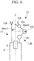
- one of the manipulators 11 and 12 may include no joint, as shown in Fig. 6 .
- the distance between the first manipulator 11 and the center axis C becomes constant, which also makes the maximum value d max1 constant. Therefore, in steps SA2 and SA3, it suffices to calculate only d max2 for the joints 12a, 12b, and 12c of the second manipulator 12.
- This embodiment differs from the first embodiment mainly in terms of the control method of the slave device 3 performed by the control portion 9. Therefore, those control details will mainly be described in this embodiment, configurations that are the same as those of the first embodiment will be given the same reference signs, and descriptions thereof will be omitted.
- a distance D' between the joints 11a and 12b when the maximum values d max1 and d max2 among the distances d are achieved is used as a reference for judging whether or not the manipulators 11 and 12 can be operated.
- the control portion 9 performs steps SB1 to SB3, as with steps SA1 to SA3 of the first embodiment. Then, the control portion 9 identifies, among the joints 11a, 11b, and 11c of the manipulator 11, the farthest joint 11a which achieves the maximum value d max1 among the distances d, and identifies, among the joints 12a, 12b, and 12c of the manipulator 12, the farthest joint 12b which achieves the maximum value d max2 among the distances d (distance calculating step SB4). Next, the control portion 9 calculates the distance D' between the farthest joints 11a and 12b on the basis of the following Expression (2) (distance calculating step SB5).
- the distance D' is the maximum distance among the distances between the joints 11a, 11b, and 11c of the first manipulator 11 and the joints 12a, 12b, and 12c of the second manipulator 12, and corresponds to the maximum dimension the manipulators 11 and 12 could reach in all directions with respect to the longitudinal direction of the inserted portion 6 when the manipulators 11 and 12 are operated in accordance with the manipulation signals.
- control portion 9 performs steps SB6 to SB8, as with the steps SA6 to SA8 of the first embodiment, except that the distance D' is used instead of the distance D.
- the inserted portion 6 is not necessarily placed in the body cavity so as to be parallel to the longitudinal direction or the flat direction of the body cavity; the inserted portion 6 may be placed in an inclined manner.
- the manipulators 11 and 12 are controlled so that the maximum distance D' of the manipulators 11 and 12 becomes equal to or less than the threshold Th when not only the direction perpendicular to the longitudinal direction of the inserted portion 6 but also all directions are taken into consideration.
- the three manipulators 11, 12, and 13 may be provided.
- step SB4 the control portion 9 identifies, of the joints 13a and 13b included in the third manipulator 13, the farthest joint 13a that achieves the maximum value d max3 among the distances, and determines the distance D' between the joints 11b and 12a for the two highest values among the obtained three maximum values d max1 , d max2 , and d max3
- This embodiment differs from the first and second embodiments mainly in terms of the control method of the slave device 3 performed by the control portion 9. Therefore, those control details will mainly be described in this embodiment, configurations that are the same as those of the first and second embodiments will be given the same reference signs, and descriptions thereof will be omitted.
- the slave device 3 is provided with the three manipulators 11, 12, and 13, and uses an area S surrounded by the joints that achieve the maximum values d max1 , d max2 , and d max3 among the distances d.
- the number of manipulators is not limited to three, and four or more manipulators may be provided.
- the control portion 9 performs steps SC1 to SC4, as with steps SB1 to SB4 of the second embodiment.
- the control portion 9 identifies: among the joints 11a, 11b, and 11c of the manipulator 11, the farthest joint 11b that achieves the maximum value d max1 among the distances d; among the joints 12a, 12b, and 12c of the manipulator 12, the farthest joint 12a that achieves the maximum value d max2 among the distances d; and, of the joints 13a and 13b of the manipulator 13, the farthest joint 13a that achieves the maximum value d max3 among the distances d (area calculating step SC4).
- the control portion 9 calculates, in the plane orthogonal to the center axis C, a triangular area S that has the farthest joints 11b, 12a, and 13a as apexes thereof (area calculating step SC5).
- the area S corresponds to the maximum area of a region surrounded by the manipulators 11, 12, and 13 in the direction perpendicular to the longitudinal direction of the inserted portion 6 when the manipulators 11 and 12 are operated in accordance with the manipulation signals.
- control portion 9 performs steps SC6 to SC8, as with steps SA6 to SA8 of the first embodiment, except that the area S is used instead of the distance D and that a predetermined threshold Th' is used instead of the predetermined threshold Th.
- the predetermined threshold Th' is determined in accordance with the dimension of the body cavity into which the manipulators 11, 12, and 13 are inserted or treatment details. This embodiment is employed, in particular, in the case of inserting the manipulators 11, 12, and 13 into a tubular body cavity, such as the large intestine, and the predetermined threshold Th' is set to be equivalent to the lateral cross-sectional area of the body cavity.
- the manipulators 11 and 12 are controlled so that the maximum area S of a region surrounded by the manipulators 11, 12, and 13 in the direction perpendicular to the longitudinal direction of the inserted portion 6 becomes equal to or less than the predetermined threshold Th'. Because a cavity wall of a body cavity such as the large intestine possesses flexibility, so long as the maximum area S is equal to or less than the lateral cross-sectional area of the body cavity, cross-sectional shape thereof can be changed in accordance with the above-described triangular shape.
- this embodiment relates to a control method of the manipulators 11 and 12 when restoring the manipulators 11 and 12 in arbitrary arrangements to predetermined reference arrangements, as shown in Fig. 12D . Therefore, those control details will mainly be described in this embodiment, configurations that are the same as those of the first to third embodiments will be given the same reference signs, and descriptions thereof will be omitted.
- the control method of the slave device 3 of this embodiment is used, for example, after operating the manipulators 11 and 12 so as to achieve arbitrary arrangements by means of the control methods described in the first to third embodiments, and it is possible to use the control method of this embodiment in combination with those in the first to third embodiments.
- control portion 9 executes a restoring flow shown in Fig. 13 by receiving restoration signals from the master device 2 (signal receiving step SD1).
- the restoration signals are input to the master device 2 by, for example, the doctor A pressing a restoration switch provided in the master device 2.
- Reference positions of the individual joints 11a, 11b, 11c, 12a, 12b, and 12c for placing the manipulators 11 and 12 in the reference arrangements are stored in the storing portion 10 in advance.
- the control portion 9 sequentially drives the joints 11a, 11b, 11c, 12a, 12b, and 12c from the third joints 11c and 12c at the base end so as to be aligned with the reference positions thereof.
- the control portion 9 calculates arrangements of the manipulators 11 and 12 when the target joint to be driven is assumed to have been moved to the reference position, and judges whether or not to execute the movements of the joint on the basis of the calculated arrangements of the manipulators 11 and 12.
- the control portion 9 selects the third joint 12c of the manipulator 12 (selecting step SD2), and calculates the maximum distance D when the third joint 12c is assumed to have been moved to the reference position thereof (steps SD3 to SD6).
- Fig. 12A shows the current arrangements of the manipulators 11 and 12
- Fig. 12B shows the arrangements of the manipulators 11 and 12 when the third joint 12c is moved to the reference position thereof.
- the procedures SD3 to SD6 of calculating the maximum distance D are the same as steps SA2 to SA5 described in the first embodiment.
- the control portion 9 compares the maximum distance D with the predetermined threshold Th (judging step SD7), and, when the maximum distance D is equal to or less than the predetermined threshold Th ("YES" in step SD7), actually operates the second manipulator 12 so as to achieve the arrangement shown in Fig. 12B by executing movement of the joint 12c to the target position thereof (movement executing step SD8). On the other hand, when the maximum distance D is greater than the predetermined threshold Th ("NO" in step SD7), the control portion 9 stops the movement of the joint 12C to the target position thereof, thus keeping the second manipulator 12 in the arrangement shown in Fig. 12A (movement stopping step SD9).
- control portion 9 repeats steps SD3 to SD9 after changing the target joint to be driven to the second joint 12b, as shown in Fig. 12C (repeating step SD11), and furthermore, the control portion 9 repeats steps SD3 to SD9 after changing the target joint to be driven to the first joint 12a (step SD11). Then, if joints that have not been placed in the reference positions thereof still remain ("NO” in step SD12) when the control of the first joint 12a is completed ("YES" in step SD10), the control portion 9 repeats, sequentially from the third joint 12c again, the restoring operation to achieve the reference positions in accordance with steps SD3 to SD9 (step SD13).
- control portion 9 restores the manipulators 11 and 12 to the reference arrangements shown in Fig. 12D by similarly moving the joints 11a, 11b, and 11c of the first manipulator 11 to the reference positions thereof.
- the manipulators 11 and 12 in arbitrary arrangements can be restored to the predetermined reference positions.
- restoration to the reference positions is sequentially executed, one at a time, from the third joints 11c and 12c at the base end.
- the operating ranges of the manipulators 11 and 12 when the joint is moved are estimated in advance, and it is judged whether or not those operating ranges fall within the allowable operating range. Then, in the case in which the operating ranges of the manipulators 11 and 12 fall within the allowable operating range, the movement of the joint is executed. On the other hand, in the case in which the operating ranges of the manipulators 11 and 12 exceed the allowable operating range, the movement of the joint is put on hold, and the driving target is shifted to the next joint.
- steps SD5 to SD7 steps SB4 to SB6 may be executed.
- whether or not the joints can be moved may be judged on the basis of the triangular area S that has the farthest joints of the individual manipulators 11, 12, and 13 as the apexes thereof, as has been described in the third embodiment.
- the joints 11a, 11b, 11c, 12a, 12b, 12c, 13a, and 13b are stopped in the case in which the maximum distance D or D' is judged to be greater than the predetermined threshold Th or Th'
- the joints 11a, 11b, 11c, 12a, 12b, 12c, 13a, and 13b may be moved to the positions at which the maximum distance D or D' reaches the predetermined threshold Th or Th' and further movements therefrom may be stopped.
- the predetermined threshold Th or Th' be smaller than the diameter or the thickness of the body cavity.
- the surgeon A may be made aware of the fact that the maximum distance D or D' will be greater than the predetermined threshold Th or Th', if the joints 11a, 11b, 11c, 12a, 12b, 12c, 13a, and 13b are moved any further.
- the movements of the joints 11a, 11b, 11c, 12a, 12b, 12c, 13a, and 13b may be stopped by limiting manipulation inputs via the master device 2 by transmitting signals to the master device 2 by means of the controller 4 so that the maximum distance D or D' does not become greater than the predetermined threshold Th or Th'.
Landscapes
- Health & Medical Sciences (AREA)
- Engineering & Computer Science (AREA)
- Life Sciences & Earth Sciences (AREA)
- Surgery (AREA)
- Robotics (AREA)
- Molecular Biology (AREA)
- Veterinary Medicine (AREA)
- Biomedical Technology (AREA)
- Heart & Thoracic Surgery (AREA)
- Medical Informatics (AREA)
- Nuclear Medicine, Radiotherapy & Molecular Imaging (AREA)
- Animal Behavior & Ethology (AREA)
- General Health & Medical Sciences (AREA)
- Public Health (AREA)
- Pathology (AREA)
- Physics & Mathematics (AREA)
- Biophysics (AREA)
- Optics & Photonics (AREA)
- Radiology & Medical Imaging (AREA)
- Mechanical Engineering (AREA)
- Signal Processing (AREA)
- Manipulator (AREA)
Abstract
Description
- The present invention relates to a manipulator-device controlling method.
- In the related art, in relation to a surgical system in which a medical manipulator is inserted into a body together with an endoscope, and the manipulator is remotely manipulated while observing the manipulator in an endoscope image, there is a known technique of limiting a range in which manipulator operation is allowed to within the viewing field of the endoscope (for example, see Patent Literature 1). With
Patent Literature 1, because a doctor can observe all movable portions of the manipulator by using the endoscope image, he/she can manipulate the manipulator so that the manipulator does not collide with tissue in the surrounding area. - {PTL 1}
U.S. Patent Application, Publication No. 2008/0065109 , specification - However, because the way in which the manipulator can be operated becomes limited in the case in which the operating range of the manipulator is limited to within the viewing field, as in
Patent Literature 1, there is a problem in that the usability is deteriorated. For example, it is difficult to cope with treatment that requires the manipulator to be operated by a large amount, while observing a treatment area in a magnified view by using an endoscope, as in suturing work. On the other hand, if the manipulator is allowed to be operated outside the endoscope viewing field, there is a problem in that, even if a portion of the manipulator is in firm contact with tissue in the surrounding area outside the viewing field, it is difficult to recognize this fact. - The present invention has been conceived in light of the above-described circumstances, and an object thereof is to provide a manipulator-device controlling method with which it is possible to prevent a manipulator from coming into firm contact with tissue in a surrounding area while maximally ensuring an allowable operating range of the manipulator inside a body.
- In order to achieve the above-described object, the present invention provides the following solutions.
- A first aspect of the present invention is a manipulator-device controlling method for a manipulator device that is provided with two or more manipulators that are arranged side-by-side and in which at least one of these manipulators has a joint at a distal-end portion thereof, the manipulator-device controlling method including: a signal receiving step of receiving manipulation signals for the manipulators; a position calculating step of calculating, on the basis of the manipulation signals received in the signal receiving step, a target position to which the joint should be moved; a distance calculating step of calculating a maximum distance between the manipulators when the joint is assumed to be placed at the target position calculated in the position calculating step; a judging step of comparing the maximum distance calculated in the distance calculating step with a predetermined threshold; a movement executing step of moving the joint to the target position in the case in which the maximum distance is judged to be equal to or less than the predetermined threshold in the judging step; and a movement stopping step of stopping the movement of the joint in the case in which the maximum distance is judged to be greater than the predetermined threshold in the judging step.
- With the first aspect of the present invention, once the manipulation signals are received in the signal receiving step, the target positions of the joints indicated by the manipulation signals is calculated in the position calculating step, and the joints are moved to the target position in the movement executing step. By doing so, it is possible to cause the manipulators to execute operations in accordance with the manipulation signals.
- In this case, the arrangement of the individual manipulators when the joints are moved to the target position thereof is estimated in the distance calculating step performed before the movement executing step, and the maximum distance between the manipulators in the estimated arrangement is calculated. The calculated maximum distance corresponds to the size of the operating ranges in the direction in which the manipulators are placed side-by-side when the manipulators are operated. By comparing this maximum distance with the predetermined threshold in the judging step, it is judged whether or not the operating ranges of the manipulators fall within the size of the allowable operating range defined by the predetermined threshold, and in the case in which the maximum distance is greater than the predetermined threshold and the operating range of the manipulators is estimated to exceed the allowable operating range, the movements of the manipulators are stopped in the movement stopping step.
- In this way, by using the target positions of the individual joints, it is possible to judge whether or not the manipulators are positioned within the allowable operating range even for a portion that cannot be viewed in an image of an observation device, such as an endoscope or the like. Therefore, it is possible to ensure the maximum allowable operating range until reaching the dimension of a body cavity in which the manipulators are placed. Furthermore, by stopping the movements of the manipulators in the case in which it is estimated that the operating range of the manipulators will exceed the allowable operating range, it is possible to prevent the manipulators from coming into firm contact with tissue in the surrounding area.
- In the above-described first aspect, in the distance calculating step, maximum values of distances to the individual manipulators from a reference line that passes through between two or more of the manipulators and that extends parallel to with these manipulators may be calculated, and a sum of the calculated maximum values may be calculated as the maximum distance.
- By doing so, with regard to the manipulator that has the joints, because one of the joints can be placed at the outermost side of the operating range, the maximum distance between the manipulators can be determined in a simple manner by effectively utilizing the target positions of the individual joints calculated in the position calculating step.
- In the above-described first aspect, two or more of the manipulators each may have the joint, and, in the distance calculating step, a maximum value of distances between the joints included in different manipulators may be calculated as the maximum distance.
- By doing so, it is possible to obtain the maximum distance between the manipulators when taking into consideration not only the arraying direction of the manipulators but also all directions. Therefore, by controlling the manipulators so that this maximum distance becomes equal to or less than the predetermined threshold, it is possible to more reliably prevent contact between the manipulator and tissue in the surrounding area, regardless of the orientation of the manipulators with respect to the tissue in the surrounding area.
- A second aspect of the present invention is a manipulator-device controlling method for a manipulator device that is provided with three or more manipulators that are arranged side-by-side and in which at least one of these manipulators has a joint, the manipulator-device controlling method including: a signal receiving step of receiving manipulation signals for the manipulators; a position calculating step of calculating, on the basis of the manipulation signals received in the signal receiving step, a target position to which the joint should be moved; an area calculating step of calculating a maximum area of a polygon that has three or more of the manipulators as apexes thereof when the joint is assumed to be placed at the target position calculated in the position calculating step; a judging step of comparing the maximum area calculated in the area calculating step with a predetermined threshold; a movement executing step of moving the joint to the target position in the case in which the maximum area is judged to be equal to or less than the predetermined threshold in the judging step; and a movement stopping step of stopping the movement of the joint in the case in which the maximum area is judged to be greater than the predetermined threshold in the judging step.
- With the second aspect of the present invention, in the area calculating step performed before the movement executing step, the arrangement of the individual manipulators when the joints are moved to the target positions thereof is estimated, and the maximum area in the arraying direction of the manipulators, which area is surrounded by the manipulators in the estimated arrangement, is calculated. The calculated maximum area corresponds to the area of the operating ranges of the manipulators in the direction in which the manipulators are placed side-by-side, when the manipulators have been operated. By comparing the maximum area with the predetermined threshold in the judging step, it is judged whether or not the area of the operating ranges of the manipulators falls within the allowable operating range that has a cross-sectional area defined by the predetermined threshold, and the movements of the manipulators are stopped in the movement stopping step in the case in which the maximum area is greater than the predetermined threshold.
- By doing so, it is possible to ensure the maximum area of the manipulators in the direction in which the manipulators are placed side-by-side within the allowable operating range until reaching the lateral cross-sectional area of the body cavity in which the manipulators are placed. Furthermore, it is possible to prevent the manipulator from coming into firm contact with tissue in the surrounding area by stopping the movements of the manipulators in the case in which the operating ranges of the manipulators are estimated to exceed the allowable operating range.
- A third aspect of the present invention is a manipulator-device controlling method for a manipulator device that is provided with two or more manipulators that are arranged side-by-side and in which at least one of these manipulators has at least one joint, the manipulator-device controlling method including: a restoring step of individually moving the joints to predetermined reference positions, wherein the restoring step includes: a selecting step of alternatively selecting the joints; a distance calculating step of calculating a maximum distance between the manipulators when the joint selected in the selecting step is assumed to be placed at the reference position thereof; a judging step of comparing the maximum distance calculated in the distance calculating step with a predetermined threshold; a movement executing step of moving the joint selected in the selecting step to the reference position thereof in the case in which the maximum distance is judged to be equal to or less than the predetermined threshold in the judging step; a movement stopping step of stopping the movement of the joint selected in the selecting step in the case in which the maximum distance is judged to be greater than the predetermined threshold in the judging step; and a repeating step of repeating the distance calculating step, the judging step, and the movement executing step or the movement stopping step after changing the joint to be selected in the selecting step.
- With the third aspect of the present invention, in the restoring step, the procedure for moving the one joint selected in the selecting step to the reference position thereof in the movement executing step is repeated in the repeating step while changing the joint, and, by sequentially moving the joints to the reference positions thereof one at a time, the manipulators in arbitrary arrangements can be restored to the predetermined reference arrangements.
- In this case, the arrangement of the manipulators when the joint is moved to the target position thereof is estimated in the distance calculating step performed before the movement executing step, and the maximum distance between the manipulators in the estimated arrangements is calculated. Then, this maximum distance is compared with the predetermined threshold in the judging step, and the movement of the joint is stopped in the movement stopping step in the case in which the maximum distance is greater than the predetermined threshold.
- By doing so, it is possible to ensure the maximum allowable operating range until reaching the dimension of the body cavity in which the manipulators are placed, and, furthermore, it is possible to prevent the manipulators from coming into firm contact with tissue in the surrounding area. {Advantageous Effects of Invention}
- The present invention affords an advantage in that it is possible to prevent a manipulator from coming into firm contact with tissue in a surrounding area while ensuring the maximum allowable operating range of the manipulator inside a body.
-
- {
Fig. 1} Fig. 1 is an overall configuration diagram of a manipulator system according to a first embodiment of the present invention. - {
Fig. 2} Fig. 2 is a functional block diagram of the manipulator system inFig. 1 . - {
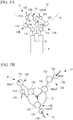
Fig. 3A} Fig. 3A is a schematic diagram of a distal-end portion of a slave device for explaining a slave-device control method according to the first embodiment of the present invention and the operation of manipulators based on this control method, showing current arrangements of the manipulators. - {
Fig. 3B} Fig. 3B shows arrangements of the manipulators, when joints thereof are assumed to have been moved to target positions by means of the slave-device control method inFig. 3A . - {
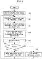
Fig. 4} Fig. 4 is a flowchart showing the slave-device control method the according to the first embodiment of the present invention. - {
Fig. 5A} Fig. 5A is a schematic diagram of a distal-end portion of a modification of the slave device, in which three manipulators are provided, showing current arrangements of the manipulators. - {
Fig. 5B} Fig. 5B is a diagram showing arrangements of the manipulators inFig. 5A , viewed from the distal-end side, when joints thereof are assumed to have been moved to the target positions. - {
Fig. 6} Fig. 6 is a schematic diagram of a distal-end portion of a modification of the slave device provided with a manipulator having no joints. - {
Fig. 7A} Fig. 7A is a schematic diagram of a distal-end portion of a slave device for explaining a slave-device control method according to a second embodiment of the present invention and the operation of manipulators based on this control method, showing current arrangements of the manipulators. - {
Fig. 7B} Fig. 7B is a diagram showing arrangements of the manipulators inFig. 7A , when joints thereof are assumed to have been moved to target positions. - {
Fig. 8} Fig. 8 is a flowchart showing the slave-device control method according to the second embodiment of the present invention. - {
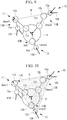
Fig. 9} Fig. 9 is a schematic diagram of a distal-end portion of a modification of the slave device, in which three manipulators are provided, showing arrangements of the manipulators, viewed from a distal-end side, when joints thereof are assumed to have been moved to the target positions. - {
Fig. 10} Fig. 10 is a schematic diagram of a distal-end portion of a slave device for explaining the slave-device control method according to a third embodiment of the present invention and the operation of manipulators based on this control method, showing the arrangement of the manipulators when joints thereof are assumed to have been moved to target positions. - {
Fig. 11} Fig. 11 is a flowchart showing the slave-device control method according to the third embodiment of the present invention. - {
Fig. 12A} Fig. 12A is a schematic diagram of a distal-end portion of a slave device for explaining a slave-device control method according to a fourth embodiment of the present invention and the operation of manipulators based on this control method. - {
Fig. 12B} Fig. 12B is a schematic diagram of the distal-end portion of the slave device after a third joint of the second manipulator has been moved to a reference position from the arrangement inFig. 12A . - {
Fig. 12C} Fig. 12C is a schematic diagram of the distal-end portion of the slave device after a second joint of the second manipulator has been moved to a reference position from the arrangement inFig. 12B . - {
Fig. 12D} Fig. 12D is a schematic diagram of the distal-end portion of the slave device showing reference arrangements of the manipulators inFig. 12A . - {
Fig. 13} Fig. 13 is a flowchart showing a slave-device control method according to the fourth embodiment of the present invention. - A
manipulator system 1 and a control method thereof according to a first embodiment of the present invention will be described below with reference toFigs. 1 to 6 . - As shown in
Fig. 1 , themanipulator system 1 according to this embodiment is provided with amaster device 2 that is manipulated by a doctor A, a slave device (manipulator device) 3 that is driven by means of inputs made via themaster device 2, a controller 4 that controls theslave device 3 on the basis of the inputs to themaster device 2, and amonitor 5. - As shown in
Figs. 2 ,3A and 3B , theslave device 3 is provided with a long, thin insertedportion 6 that can be inserted into the body of a patient P, twomulti-joint manipulators portion 6 and that are placed side-by-side, driveportions manipulators endoscope 8 that captures images of themanipulators slave device 3 outputs the endoscope images acquired by theendoscope 8 to themonitor 5. Although thedrive portions Fig. 2 , they may be provided separate from the controller 4. - The
manipulator 11 has, sequentially from the distal end thereof, anend effector 11A and ajoint portion 11B formed of a plurality of (three, in this example) joints 11a, 11b, and 11c that are linked with each other in series. Similarly, themanipulator 12 has, sequentially from the distal end thereof, anend effector 12A and ajoint portion 12B formed of a plurality of (three, in this example) joints 12a, 12b, and 12c that are linked with each other in series. Thejoints portion 6. The positions and shapes of themanipulators individual joints drive portions end effectors end effectors - The numbers of joints in the
manipulators manipulators - The
master device 2 generates manipulation signals that correspond to manipulations performed by the doctor A and transmits the generated manipulation signals to the controller 4. - The controller 4 is provided with a
control portion 9 that controls thedrive portions master device 2 and that, by doing so, causes themanipulators portion 10. - Next, a control method of the
slave device 3, via thecontrol portion 9, which corresponds to the manipulator-device controlling method according to the present invention, will be described by using, as an example, the case in which themanipulators Fig. 3B starting from the arrangements shown inFig. 3A . - As shown in
Fig. 4 , once the manipulation signals are received from the master device 2 (signal receiving step SA1), thecontrol portion 9 calculates, by using forward kinematics, target positions of theindividual joints manipulators individual joints Fig. 3B are calculated as the target positions. This calculation uses information about the dimensions of themanipulators portion 10 in advance and the current positions of theindividual joints - Next,
control portion 9 judges, on the basis of the calculated target positions, whether or not to execute movements of theindividual joints - Specifically, first, the
control portion 9 calculates distances d to the target positions of theindividual joints portion 6 in the longitudinal direction on the basis of Expression (1) below (distance calculating step SA3). In Expression (1), the coordinates of the target positions of theindividual joints 
- Next, the
control portion 9 identifies a maximum value dmax1 among the distances d calculated for thejoints first manipulator 11, and identifies a maximum value dmax2 among the distances d calculated for thejoints Fig. 3B , the distance for the first joint 11a, that is, the most distal end, of thefirst manipulator 11 and the distance for the second joint 12b, that is, the second joint from the distal end, of thesecond manipulator 12 are identified. - Next, the
control portion 9 calculates a maximum distance D by summing the two identified maximum values dmax1 and dmax2 (distance calculating step SA5). This maximum distance D is a maximum distance that themanipulators portion 6 when themanipulators - The
control portion 9 compares the maximum distance D with a predetermined threshold Th (judging step SA6), and, when the maximum distance D is equal to or less than the predetermined threshold Th ("YES" in step SA6), actually operates themanipulators Fig. 3B by executing movements of thejoints control portion 9 stops the movements of thejoints manipulators Fig. 3A (movement stopping step SA8). - In other words, in step SA6, it is judged whether or not the
entire manipulators portion 6. Then, when it is judged that the operation only in the allowable operating range is possible, the operations of themanipulators manipulators manipulators - Here, the predetermined threshold Th is determined in accordance with the dimension of the body cavity into which the
manipulators manipulators manipulators slave device 3 by selecting an appropriate value from values that are pre-registered in the controller 4. - Next, the operation of the thus-configured
manipulator system 1 will be described. - In order to treat an affected part that exists in a body cavity of the patient P by using the
manipulator system 1 according to this embodiment, the insertedportion 6 is inserted into the body cavity from the distal end thereof, and theend effectors end effectors manipulators master device 2. - At this time, in the
manipulator system 1, before causing themanipulators master device 2, the operating ranges of themanipulators individual joints manipulators manipulators manipulators manipulators - In this case, with the
manipulator system 1 and the control method thereof according to this embodiment, by estimating the positions of the individual components of themanipulators individual joints manipulators endoscope 8. Therefore, there is an advantage in that it is possible to ensure the maximum allowable operating range of themanipulators - Furthermore, because the overall operations of the
manipulators manipulators manipulators manipulators - Although this embodiment has assumed that the two
manipulators manipulators Figs. 5A and 5B . - In this case, it suffices that, in step SA4, the
control portion 9 identifies a maximum value dmax3 among distances d calculated forjoints third manipulator 13, and determines the maximum distance D by summing the highest two values among the obtained three maximum values dmax1, dmax2, and dmax3. - Although this embodiment has assumed that the two
manipulators joints manipulators Fig. 6 . For example, in the case in which thefirst manipulator 11 has no joint, the distance between thefirst manipulator 11 and the center axis C becomes constant, which also makes the maximum value dmax1 constant. Therefore, in steps SA2 and SA3, it suffices to calculate only dmax2 for thejoints second manipulator 12. - Next, a
manipulator system 1 according to a second embodiment of the present invention will be described with reference toFigs. 7A to 9 . - This embodiment differs from the first embodiment mainly in terms of the control method of the
slave device 3 performed by thecontrol portion 9. Therefore, those control details will mainly be described in this embodiment, configurations that are the same as those of the first embodiment will be given the same reference signs, and descriptions thereof will be omitted. - In this embodiment, as shown in
Figs. 7A and 7B , a distance D' between thejoints manipulators - Specifically, as shown in
Fig. 8 , thecontrol portion 9 performs steps SB1 to SB3, as with steps SA1 to SA3 of the first embodiment. Then, thecontrol portion 9 identifies, among thejoints manipulator 11, the farthest joint 11a which achieves the maximum value dmax1 among the distances d, and identifies, among thejoints manipulator 12, the farthest joint 12b which achieves the maximum value dmax2 among the distances d (distance calculating step SB4). Next, thecontrol portion 9 calculates the distance D' between thefarthest joints first manipulator 11 are defined as (x1, y1, z1), and the coordinates of the target position of the farthest joint of thesecond manipulator 12 are defined as (x2, y2, z2).
- The distance D' is the maximum distance among the distances between the
joints first manipulator 11 and thejoints second manipulator 12, and corresponds to the maximum dimension themanipulators portion 6 when themanipulators - In the following, the
control portion 9 performs steps SB6 to SB8, as with the steps SA6 to SA8 of the first embodiment, except that the distance D' is used instead of the distance D. - With the thus-configured
manipulator system 1 and the control method thereof according to this embodiment, the insertedportion 6 is not necessarily placed in the body cavity so as to be parallel to the longitudinal direction or the flat direction of the body cavity; the insertedportion 6 may be placed in an inclined manner. In this embodiment, themanipulators manipulators portion 6 but also all directions are taken into consideration. - By doing so, because the overall operations of the
manipulators manipulators manipulators - Because other operational advantages of this embodiment are the same as those of the first embodiment, descriptions thereof will be omitted.
- As shown in
Fig. 9 , in this embodiment also, the threemanipulators - In this case, it suffices that, in step SB4, the
control portion 9 identifies, of thejoints third manipulator 13, the farthest joint 13a that achieves the maximum value dmax3 among the distances, and determines the distance D' between thejoints - Next, a
manipulator system 1 according to a third embodiment of the present invention will be described with reference toFigs. 10 and11 . - This embodiment differs from the first and second embodiments mainly in terms of the control method of the
slave device 3 performed by thecontrol portion 9. Therefore, those control details will mainly be described in this embodiment, configurations that are the same as those of the first and second embodiments will be given the same reference signs, and descriptions thereof will be omitted. - In this embodiment, as shown in
Fig. 10 , theslave device 3 is provided with the threemanipulators - Specifically, as shown in
Fig. 11 , thecontrol portion 9 performs steps SC1 to SC4, as with steps SB1 to SB4 of the second embodiment. By doing so, thecontrol portion 9 identifies: among thejoints manipulator 11, the farthest joint 11b that achieves the maximum value dmax1 among the distances d; among thejoints manipulator 12, the farthest joint 12a that achieves the maximum value dmax2 among the distances d; and, of thejoints manipulator 13, the farthest joint 13a that achieves the maximum value dmax3 among the distances d (area calculating step SC4). Next, thecontrol portion 9 calculates, in the plane orthogonal to the center axis C, a triangular area S that has thefarthest joints Fig. 10 , the area S corresponds to the maximum area of a region surrounded by themanipulators portion 6 when themanipulators - Subsequently, the
control portion 9 performs steps SC6 to SC8, as with steps SA6 to SA8 of the first embodiment, except that the area S is used instead of the distance D and that a predetermined threshold Th' is used instead of the predetermined threshold Th. The predetermined threshold Th' is determined in accordance with the dimension of the body cavity into which themanipulators manipulators - With the thus-configured
manipulator system 1 and the control method thereof according to this embodiment, themanipulators manipulators portion 6 becomes equal to or less than the predetermined threshold Th'. Because a cavity wall of a body cavity such as the large intestine possesses flexibility, so long as the maximum area S is equal to or less than the lateral cross-sectional area of the body cavity, cross-sectional shape thereof can be changed in accordance with the above-described triangular shape. In other words, with this embodiment, because the operations of themanipulators manipulators manipulators - Because other operational advantages of this embodiment are the same as those of the first embodiment, descriptions thereof will be omitted.
- Next, a
manipulator system 1 according to a fourth embodiment of the present invention will be described with reference toFigs. 12A to 13 . - As shown in
Fig. 12A , this embodiment relates to a control method of themanipulators manipulators Fig. 12D . Therefore, those control details will mainly be described in this embodiment, configurations that are the same as those of the first to third embodiments will be given the same reference signs, and descriptions thereof will be omitted. - The control method of the
slave device 3 of this embodiment is used, for example, after operating themanipulators - In this embodiment, the
control portion 9 executes a restoring flow shown inFig. 13 by receiving restoration signals from the master device 2 (signal receiving step SD1). The restoration signals are input to themaster device 2 by, for example, the doctor A pressing a restoration switch provided in themaster device 2. - Reference positions of the
individual joints manipulators portion 10 in advance. Thecontrol portion 9 sequentially drives thejoints third joints control portion 9 calculates arrangements of themanipulators manipulators - Specifically, first, the
control portion 9 selects the third joint 12c of the manipulator 12 (selecting step SD2), and calculates the maximum distance D when the third joint 12c is assumed to have been moved to the reference position thereof (steps SD3 to SD6).Fig. 12A shows the current arrangements of themanipulators Fig. 12B shows the arrangements of themanipulators - The
control portion 9 compares the maximum distance D with the predetermined threshold Th (judging step SD7), and, when the maximum distance D is equal to or less than the predetermined threshold Th ("YES" in step SD7), actually operates thesecond manipulator 12 so as to achieve the arrangement shown inFig. 12B by executing movement of the joint 12c to the target position thereof (movement executing step SD8). On the other hand, when the maximum distance D is greater than the predetermined threshold Th ("NO" in step SD7), thecontrol portion 9 stops the movement of the joint 12C to the target position thereof, thus keeping thesecond manipulator 12 in the arrangement shown inFig. 12A (movement stopping step SD9). - Next, the
control portion 9 repeats steps SD3 to SD9 after changing the target joint to be driven to the second joint 12b, as shown inFig. 12C (repeating step SD11), and furthermore, thecontrol portion 9 repeats steps SD3 to SD9 after changing the target joint to be driven to the first joint 12a (step SD11). Then, if joints that have not been placed in the reference positions thereof still remain ("NO" in step SD12) when the control of the first joint 12a is completed ("YES" in step SD10), thecontrol portion 9 repeats, sequentially from the third joint 12c again, the restoring operation to achieve the reference positions in accordance with steps SD3 to SD9 (step SD13). - Furthermore, although not shown in
Fig. 13 , after completing the movement of all of thejoints second manipulator 12 to the reference positions thereof, thecontrol portion 9 finally restores themanipulators Fig. 12D by similarly moving thejoints first manipulator 11 to the reference positions thereof. - Next, the operation of the thus-configured
manipulator system 1 will be described. - When the doctor A presses the restoration switch while performing or after completing treatment of an affected part, the
manipulators - At this time, in the
manipulator system 1, restoration to the reference positions is sequentially executed, one at a time, from thethird joints manipulators manipulators manipulators manipulators - As has been described above, with the
manipulator system 1 and the control method thereof according to this embodiment, there is an advantage in that it is possible to maximally ensure the allowable operating range of themanipulators manipulators - In this embodiment, although it is judged whether or not the joints can be moved by using the same method as in the first embodiment, alternatively, the method described in the second embodiment may be employed. In other words, instead of steps SD5 to SD7, steps SB4 to SB6 may be executed.
- In addition, in the case in which the three
manipulators individual manipulators - Note that, in the individual embodiments described above, although the movements of the
joints joints - In addition, at the point in time when the
joints joints - Furthermore, in the case in which the maximum distance D or D' is judged to be greater than the predetermined threshold Th or Th', the movements of the
joints master device 2 by transmitting signals to themaster device 2 by means of the controller 4 so that the maximum distance D or D' does not become greater than the predetermined threshold Th or Th'. -
- 1
- manipulator system
- 2
- master device
- 3
- slave device (manipulator device)
- 4
- controller
- 5
- monitor
- 6
- inserted portion
- 8
- endoscope
- 9
- control portion
- 10
- storing portion
- 11, 12, 13
- manipulator
- 11A, 12A, 13A
- end effector
- 11B, 12B, 13B
- joint portion
- 11a, 11b, 11c, 12a, 12b, 12c, 13a, 13b
- joint
- 71, 72
- drive portion
- A
- doctor
- P
- patient
- F
- endoscope viewing field
- SA1, SB1, SC1, SD1
- signal receiving step
- SA2, SB2, SC2, SD3
- position calculating step
- SA3, SA4, SA5, SB3, SB4, SB5, SD4, SD5, SD6
- distance calculating step
- SA6, SB6, SC6, SD7
- judging step
- SA7, SB7, SC7, SD8
- movement executing step
- SA8, SB8, SC8, SD9
- movement stopping step
- SC4, SC5
- area calculating step
- SD2
- selecting step
- SD11
- repeating step
Claims (5)
- A manipulator-device controlling method for a manipulator device that is provided with two or more manipulators that are arranged side-by-side and in which at least one of these manipulators has a joint, the manipulator-device controlling method comprising:a signal receiving step of receiving manipulation signals for the manipulators;a position calculating step of calculating, on the basis of the manipulation signals received in the signal receiving step, a target position to which the joint should be moved;a distance calculating step of calculating a maximum distance between the manipulators when the joint is assumed to be placed at the target position calculated in the position calculating step;a judging step of comparing the maximum distance calculated in the distance calculating step with a predetermined threshold;a movement executing step of moving the joint to the target position in the case in which the maximum distance is judged to be equal to or less than the predetermined threshold in the judging step; anda movement stopping step of stopping the movement of the joint in the case in which the maximum distance is judged to be greater than the predetermined threshold in the judging step.
- A manipulator-device controlling method according to Claim 1, wherein, in the distance calculating step, maximum values of distances to the individual manipulators from a reference line that passes through between two or more of the manipulators and that extends parallel to with these manipulators are calculated, and a sum of the calculated maximum values is calculated as the maximum distance.
- A manipulator-device controlling method according to Claim 1,
wherein two or more of the manipulators each have the joint, and,
in the distance calculating step, a maximum value of distances between the joints included in different manipulators is calculated as the maximum distance. - A manipulator-device controlling method for a manipulator device that is provided with three or more manipulators that are arranged side-by-side and in which at least one of these manipulators has a joint, the manipulator-device controlling method comprising:a signal receiving step of receiving manipulation signals for the manipulators;a position calculating step of calculating, on the basis of the manipulation signals received in the signal receiving step, a target position to which the joint should be moved;an area calculating step of calculating a maximum area of a polygon that has three or more of the manipulators as apexes thereof when the joint is assumed to be placed at the target position calculated in the position calculating step;a judging step of comparing the maximum area calculated in the area calculating step with a predetermined threshold;a movement executing step of moving the joint to the target position in the case in which the maximum area is judged to be equal to or less than the predetermined threshold in the judging step; anda movement stopping step of stopping the movement of the joint in the case in which the maximum area is judged to be greater than the predetermined threshold in the judging step.
- A manipulator-device controlling method for a manipulator device that is provided with two or more manipulators that are arranged side-by-side and in which at least one of these manipulators has at least one joint, the manipulator-device controlling method comprising:a restoring step of individually moving the joints to predetermined reference positions,wherein the restoring step includes:a selecting step of alternatively selecting the joints;a distance calculating step of calculating a maximum distance between the manipulators when the joint selected in the selecting step is assumed to be placed at the reference position thereof;a judging step of comparing the maximum distance calculated in the distance calculating step with a predetermined threshold;a movement executing step of moving the joint selected in the selecting step to the reference position thereof in the case in which the maximum distance is judged to be equal to or less than the predetermined threshold in the judging step;a movement stopping step of stopping the movement of the joint selected in the selecting step in the case in which the maximum distance is judged to be greater than the predetermined threshold in the judging step; anda repeating step of repeating the distance calculating step, the judging step, and the movement executing step or the movement stopping step after changing the joint to be selected in the selecting step.
Applications Claiming Priority (2)
| Application Number | Priority Date | Filing Date | Title |
|---|---|---|---|
| JP2014028875A JP6218631B2 (en) | 2014-02-18 | 2014-02-18 | Method of operating a manipulator device |
| PCT/JP2015/053539 WO2015125649A1 (en) | 2014-02-18 | 2015-02-09 | Manipulator device control method |
Publications (3)
| Publication Number | Publication Date |
|---|---|
| EP3108843A1 true EP3108843A1 (en) | 2016-12-28 |
| EP3108843A4 EP3108843A4 (en) | 2017-08-30 |
| EP3108843B1 EP3108843B1 (en) | 2019-04-17 |
Family
ID=53878155
Family Applications (1)
| Application Number | Title | Priority Date | Filing Date |
|---|---|---|---|
| EP15751547.9A Active EP3108843B1 (en) | 2014-02-18 | 2015-02-09 | Manipulator device controller |
Country Status (5)
| Country | Link |
|---|---|
| US (1) | US9981386B2 (en) |
| EP (1) | EP3108843B1 (en) |
| JP (1) | JP6218631B2 (en) |
| CN (1) | CN105979903B (en) |
| WO (1) | WO2015125649A1 (en) |
Families Citing this family (9)
| Publication number | Priority date | Publication date | Assignee | Title |
|---|---|---|---|---|
| EP4005522B1 (en) * | 2014-03-17 | 2025-09-03 | Intuitive Surgical Operations, Inc. | Structural adjustment systems for a teleoperational medical system |
| WO2017115425A1 (en) * | 2015-12-28 | 2017-07-06 | オリンパス株式会社 | Medical manipulator system |
| JP6831642B2 (en) * | 2016-04-15 | 2021-02-17 | 川崎重工業株式会社 | Surgical system |
| US10182875B2 (en) | 2016-08-16 | 2019-01-22 | Ethicon Llc | Robotic visualization and collision avoidance |
| US10413373B2 (en) | 2016-08-16 | 2019-09-17 | Ethicon, Llc | Robotic visualization and collision avoidance |
| CN106625724B (en) * | 2016-11-29 | 2019-02-22 | 福州大学 | A cloud control platform-oriented industrial robot ontology security control method |
| JP7085400B2 (en) | 2018-04-27 | 2022-06-16 | 川崎重工業株式会社 | Surgical system |
| CN110132694A (en) * | 2019-05-27 | 2019-08-16 | 福州迈新生物技术开发有限公司 | A kind of method that full-automatic pathological staining system reduces failure secondary damage |
| GB2605808B (en) * | 2021-04-14 | 2023-08-30 | Prec Robotics Limited | An apparatus, computer-implemented method and computer program |
Family Cites Families (16)
| Publication number | Priority date | Publication date | Assignee | Title |
|---|---|---|---|---|
| JPH03178788A (en) | 1989-12-06 | 1991-08-02 | Hitachi Ltd | Control method for manipulator |
| US10555775B2 (en) * | 2005-05-16 | 2020-02-11 | Intuitive Surgical Operations, Inc. | Methods and system for performing 3-D tool tracking by fusion of sensor and/or camera derived data during minimally invasive robotic surgery |
| JP4488312B2 (en) * | 2005-07-08 | 2010-06-23 | オリンパス株式会社 | Medical manipulator system |
| JP2007029232A (en) * | 2005-07-25 | 2007-02-08 | Hitachi Medical Corp | System for supporting endoscopic operation |
| US20080064927A1 (en) | 2006-06-13 | 2008-03-13 | Intuitive Surgical, Inc. | Minimally invasrive surgery guide tube |
| US8377045B2 (en) * | 2006-06-13 | 2013-02-19 | Intuitive Surgical Operations, Inc. | Extendable suction surface for bracing medial devices during robotically assisted medical procedures |
| JP4528312B2 (en) * | 2007-02-02 | 2010-08-18 | 川田工業株式会社 | Dual-arm robot shoulder width limiting device and dual-arm robot equipped with the device |
| US9138129B2 (en) * | 2007-06-13 | 2015-09-22 | Intuitive Surgical Operations, Inc. | Method and system for moving a plurality of articulated instruments in tandem back towards an entry guide |
| US8620473B2 (en) | 2007-06-13 | 2013-12-31 | Intuitive Surgical Operations, Inc. | Medical robotic system with coupled control modes |
| CN101352854B (en) * | 2008-07-17 | 2011-01-26 | 上海交通大学 | Intelligent unit, system and method for autonomous obstacle avoidance of teleoperated planar redundant manipulator |
| CN101870104B (en) * | 2009-04-25 | 2012-09-19 | 鸿富锦精密工业(深圳)有限公司 | Manipulator inverse moving method |
| US9492927B2 (en) * | 2009-08-15 | 2016-11-15 | Intuitive Surgical Operations, Inc. | Application of force feedback on an input device to urge its operator to command an articulated instrument to a preferred pose |
| US8386080B2 (en) | 2009-09-15 | 2013-02-26 | Harris Corporation | Robotic apparatus implementing collision avoidance scheme and associated methods |
| US9119655B2 (en) * | 2012-08-03 | 2015-09-01 | Stryker Corporation | Surgical manipulator capable of controlling a surgical instrument in multiple modes |
| JP5669590B2 (en) * | 2011-01-20 | 2015-02-12 | オリンパス株式会社 | Master-slave manipulator and medical master-slave manipulator |
| US8791641B2 (en) * | 2011-09-16 | 2014-07-29 | Cree, Inc. | Solid-state lighting apparatus and methods using energy storage |
-
2014
- 2014-02-18 JP JP2014028875A patent/JP6218631B2/en active Active
-
2015
- 2015-02-09 WO PCT/JP2015/053539 patent/WO2015125649A1/en not_active Ceased
- 2015-02-09 EP EP15751547.9A patent/EP3108843B1/en active Active
- 2015-02-09 CN CN201580008351.XA patent/CN105979903B/en active Active
-
2016
- 2016-08-05 US US15/229,340 patent/US9981386B2/en active Active
Also Published As
| Publication number | Publication date |
|---|---|
| US20160339586A1 (en) | 2016-11-24 |
| JP2015150340A (en) | 2015-08-24 |
| CN105979903A (en) | 2016-09-28 |
| US9981386B2 (en) | 2018-05-29 |
| WO2015125649A1 (en) | 2015-08-27 |
| EP3108843B1 (en) | 2019-04-17 |
| EP3108843A4 (en) | 2017-08-30 |
| CN105979903B (en) | 2018-08-17 |
| JP6218631B2 (en) | 2017-10-25 |
Similar Documents
| Publication | Publication Date | Title |
|---|---|---|
| EP3108843A1 (en) | Manipulator device control method | |
| JP4672031B2 (en) | Medical instruments | |
| US10369707B2 (en) | Joint of robot arm and surgical instrument | |
| JP4744595B2 (en) | Endoscopic surgical instrument | |
| JP5017076B2 (en) | Manipulator system and manipulator control method | |
| JP3419869B2 (en) | Medical equipment | |
| US12178528B2 (en) | Surgical robotic systems and methods of tracking usage of surgical instruments thereof | |
| US20190314021A1 (en) | System for performing extraluminal coronary bypass and method of operation thereof | |
| WO2019116592A1 (en) | Device for adjusting display image of endoscope, and surgery system | |
| CN112770688A (en) | Method and system for providing assistance to a user of a surgical robotic system | |
| EP3316759B1 (en) | Apparatus for controlling manipulator | |
| KR20130140794A (en) | Systems for detecting clamping or firing failure | |
| CN108697304A (en) | Medical information processing unit, information processing method, medical information processing system | |
| KR101161242B1 (en) | Tubular type manipulator surgical robot system with image guidance for minimal invasive surgery | |
| Wortman et al. | Single-site colectomy with miniature in vivo robotic platform | |
| US20160354164A1 (en) | Surgical system and medical-device-interference avoidance method | |
| US20100081886A1 (en) | Surgical manipulator system | |
| EP3025670A1 (en) | Medical master-slave system control method | |
| Roh et al. | Single-port surgical robot system with flexible surgical instruments | |
| US20170128146A1 (en) | Medical manipulator and treatment tool package | |
| JP5085234B2 (en) | Medical procedure equipment | |
| US20200315740A1 (en) | Identification and assignment of instruments in a surgical system using camera recognition | |
| JP6214837B1 (en) | Medical manipulator system | |
| US20100082043A1 (en) | Surgical manipulator system | |
| KR20160040811A (en) | A joint unit and a surgical instrument comprising thereof |
Legal Events
| Date | Code | Title | Description |
|---|---|---|---|
| STAA | Information on the status of an ep patent application or granted ep patent |
Free format text: STATUS: THE INTERNATIONAL PUBLICATION HAS BEEN MADE |
|
| PUAI | Public reference made under article 153(3) epc to a published international application that has entered the european phase |
Free format text: ORIGINAL CODE: 0009012 |
|
| STAA | Information on the status of an ep patent application or granted ep patent |
Free format text: STATUS: REQUEST FOR EXAMINATION WAS MADE |
|
| 17P | Request for examination filed |
Effective date: 20160915 |
|
| AK | Designated contracting states |
Kind code of ref document: A1 Designated state(s): AL AT BE BG CH CY CZ DE DK EE ES FI FR GB GR HR HU IE IS IT LI LT LU LV MC MK MT NL NO PL PT RO RS SE SI SK SM TR |
|
| AX | Request for extension of the european patent |
Extension state: BA ME |
|
| DAX | Request for extension of the european patent (deleted) | ||
| A4 | Supplementary search report drawn up and despatched |
Effective date: 20170731 |
|
| RIC1 | Information provided on ipc code assigned before grant |
Ipc: A61B 90/00 20160101AFI20170725BHEP Ipc: A61B 1/00 20060101ALI20170725BHEP Ipc: B25J 19/06 20060101ALI20170725BHEP |
|
| GRAP | Despatch of communication of intention to grant a patent |
Free format text: ORIGINAL CODE: EPIDOSNIGR1 |
|
| STAA | Information on the status of an ep patent application or granted ep patent |
Free format text: STATUS: GRANT OF PATENT IS INTENDED |
|
| INTG | Intention to grant announced |
Effective date: 20181116 |
|
| GRAS | Grant fee paid |
Free format text: ORIGINAL CODE: EPIDOSNIGR3 |
|
| GRAA | (expected) grant |
Free format text: ORIGINAL CODE: 0009210 |
|
| STAA | Information on the status of an ep patent application or granted ep patent |
Free format text: STATUS: THE PATENT HAS BEEN GRANTED |
|
| AK | Designated contracting states |
Kind code of ref document: B1 Designated state(s): AL AT BE BG CH CY CZ DE DK EE ES FI FR GB GR HR HU IE IS IT LI LT LU LV MC MK MT NL NO PL PT RO RS SE SI SK SM TR |
|
| REG | Reference to a national code |
Ref country code: GB Ref legal event code: FG4D |
|
| REG | Reference to a national code |
Ref country code: CH Ref legal event code: EP |
|
| REG | Reference to a national code |
Ref country code: DE Ref legal event code: R096 Ref document number: 602015028496 Country of ref document: DE |
|
| REG | Reference to a national code |
Ref country code: AT Ref legal event code: REF Ref document number: 1120728 Country of ref document: AT Kind code of ref document: T Effective date: 20190515 Ref country code: IE Ref legal event code: FG4D |
|
| REG | Reference to a national code |
Ref country code: NL Ref legal event code: MP Effective date: 20190417 |
|
| REG | Reference to a national code |
Ref country code: LT Ref legal event code: MG4D |
|
| PG25 | Lapsed in a contracting state [announced via postgrant information from national office to epo] |
Ref country code: NL Free format text: LAPSE BECAUSE OF FAILURE TO SUBMIT A TRANSLATION OF THE DESCRIPTION OR TO PAY THE FEE WITHIN THE PRESCRIBED TIME-LIMIT Effective date: 20190417 |
|
| PG25 | Lapsed in a contracting state [announced via postgrant information from national office to epo] |
Ref country code: ES Free format text: LAPSE BECAUSE OF FAILURE TO SUBMIT A TRANSLATION OF THE DESCRIPTION OR TO PAY THE FEE WITHIN THE PRESCRIBED TIME-LIMIT Effective date: 20190417 Ref country code: LT Free format text: LAPSE BECAUSE OF FAILURE TO SUBMIT A TRANSLATION OF THE DESCRIPTION OR TO PAY THE FEE WITHIN THE PRESCRIBED TIME-LIMIT Effective date: 20190417 Ref country code: SE Free format text: LAPSE BECAUSE OF FAILURE TO SUBMIT A TRANSLATION OF THE DESCRIPTION OR TO PAY THE FEE WITHIN THE PRESCRIBED TIME-LIMIT Effective date: 20190417 Ref country code: HR Free format text: LAPSE BECAUSE OF FAILURE TO SUBMIT A TRANSLATION OF THE DESCRIPTION OR TO PAY THE FEE WITHIN THE PRESCRIBED TIME-LIMIT Effective date: 20190417 Ref country code: PT Free format text: LAPSE BECAUSE OF FAILURE TO SUBMIT A TRANSLATION OF THE DESCRIPTION OR TO PAY THE FEE WITHIN THE PRESCRIBED TIME-LIMIT Effective date: 20190817 Ref country code: AL Free format text: LAPSE BECAUSE OF FAILURE TO SUBMIT A TRANSLATION OF THE DESCRIPTION OR TO PAY THE FEE WITHIN THE PRESCRIBED TIME-LIMIT Effective date: 20190417 Ref country code: FI Free format text: LAPSE BECAUSE OF FAILURE TO SUBMIT A TRANSLATION OF THE DESCRIPTION OR TO PAY THE FEE WITHIN THE PRESCRIBED TIME-LIMIT Effective date: 20190417 Ref country code: NO Free format text: LAPSE BECAUSE OF FAILURE TO SUBMIT A TRANSLATION OF THE DESCRIPTION OR TO PAY THE FEE WITHIN THE PRESCRIBED TIME-LIMIT Effective date: 20190717 |
|
| PG25 | Lapsed in a contracting state [announced via postgrant information from national office to epo] |
Ref country code: PL Free format text: LAPSE BECAUSE OF FAILURE TO SUBMIT A TRANSLATION OF THE DESCRIPTION OR TO PAY THE FEE WITHIN THE PRESCRIBED TIME-LIMIT Effective date: 20190417 Ref country code: LV Free format text: LAPSE BECAUSE OF FAILURE TO SUBMIT A TRANSLATION OF THE DESCRIPTION OR TO PAY THE FEE WITHIN THE PRESCRIBED TIME-LIMIT Effective date: 20190417 Ref country code: GR Free format text: LAPSE BECAUSE OF FAILURE TO SUBMIT A TRANSLATION OF THE DESCRIPTION OR TO PAY THE FEE WITHIN THE PRESCRIBED TIME-LIMIT Effective date: 20190718 Ref country code: BG Free format text: LAPSE BECAUSE OF FAILURE TO SUBMIT A TRANSLATION OF THE DESCRIPTION OR TO PAY THE FEE WITHIN THE PRESCRIBED TIME-LIMIT Effective date: 20190717 Ref country code: RS Free format text: LAPSE BECAUSE OF FAILURE TO SUBMIT A TRANSLATION OF THE DESCRIPTION OR TO PAY THE FEE WITHIN THE PRESCRIBED TIME-LIMIT Effective date: 20190417 |
|
| REG | Reference to a national code |
Ref country code: AT Ref legal event code: MK05 Ref document number: 1120728 Country of ref document: AT Kind code of ref document: T Effective date: 20190417 |
|
| PG25 | Lapsed in a contracting state [announced via postgrant information from national office to epo] |
Ref country code: IS Free format text: LAPSE BECAUSE OF FAILURE TO SUBMIT A TRANSLATION OF THE DESCRIPTION OR TO PAY THE FEE WITHIN THE PRESCRIBED TIME-LIMIT Effective date: 20190817 |
|
| REG | Reference to a national code |
Ref country code: DE Ref legal event code: R097 Ref document number: 602015028496 Country of ref document: DE |
|
| PG25 | Lapsed in a contracting state [announced via postgrant information from national office to epo] |
Ref country code: CZ Free format text: LAPSE BECAUSE OF FAILURE TO SUBMIT A TRANSLATION OF THE DESCRIPTION OR TO PAY THE FEE WITHIN THE PRESCRIBED TIME-LIMIT Effective date: 20190417 Ref country code: RO Free format text: LAPSE BECAUSE OF FAILURE TO SUBMIT A TRANSLATION OF THE DESCRIPTION OR TO PAY THE FEE WITHIN THE PRESCRIBED TIME-LIMIT Effective date: 20190417 Ref country code: SK Free format text: LAPSE BECAUSE OF FAILURE TO SUBMIT A TRANSLATION OF THE DESCRIPTION OR TO PAY THE FEE WITHIN THE PRESCRIBED TIME-LIMIT Effective date: 20190417 Ref country code: EE Free format text: LAPSE BECAUSE OF FAILURE TO SUBMIT A TRANSLATION OF THE DESCRIPTION OR TO PAY THE FEE WITHIN THE PRESCRIBED TIME-LIMIT Effective date: 20190417 Ref country code: AT Free format text: LAPSE BECAUSE OF FAILURE TO SUBMIT A TRANSLATION OF THE DESCRIPTION OR TO PAY THE FEE WITHIN THE PRESCRIBED TIME-LIMIT Effective date: 20190417 Ref country code: DK Free format text: LAPSE BECAUSE OF FAILURE TO SUBMIT A TRANSLATION OF THE DESCRIPTION OR TO PAY THE FEE WITHIN THE PRESCRIBED TIME-LIMIT Effective date: 20190417 |
|
| PLBE | No opposition filed within time limit |
Free format text: ORIGINAL CODE: 0009261 |
|
| STAA | Information on the status of an ep patent application or granted ep patent |
Free format text: STATUS: NO OPPOSITION FILED WITHIN TIME LIMIT |
|
| PG25 | Lapsed in a contracting state [announced via postgrant information from national office to epo] |
Ref country code: IT Free format text: LAPSE BECAUSE OF FAILURE TO SUBMIT A TRANSLATION OF THE DESCRIPTION OR TO PAY THE FEE WITHIN THE PRESCRIBED TIME-LIMIT Effective date: 20190417 Ref country code: SM Free format text: LAPSE BECAUSE OF FAILURE TO SUBMIT A TRANSLATION OF THE DESCRIPTION OR TO PAY THE FEE WITHIN THE PRESCRIBED TIME-LIMIT Effective date: 20190417 |
|
| 26N | No opposition filed |
Effective date: 20200120 |
|
| PG25 | Lapsed in a contracting state [announced via postgrant information from national office to epo] |
Ref country code: TR Free format text: LAPSE BECAUSE OF FAILURE TO SUBMIT A TRANSLATION OF THE DESCRIPTION OR TO PAY THE FEE WITHIN THE PRESCRIBED TIME-LIMIT Effective date: 20190417 |
|
| PG25 | Lapsed in a contracting state [announced via postgrant information from national office to epo] |
Ref country code: SI Free format text: LAPSE BECAUSE OF FAILURE TO SUBMIT A TRANSLATION OF THE DESCRIPTION OR TO PAY THE FEE WITHIN THE PRESCRIBED TIME-LIMIT Effective date: 20190417 |
|
| REG | Reference to a national code |
Ref country code: DE Ref legal event code: R119 Ref document number: 602015028496 Country of ref document: DE |
|
| REG | Reference to a national code |
Ref country code: CH Ref legal event code: PL |
|
| GBPC | Gb: european patent ceased through non-payment of renewal fee |
Effective date: 20200209 |
|
| REG | Reference to a national code |
Ref country code: BE Ref legal event code: MM Effective date: 20200229 |
|
| PG25 | Lapsed in a contracting state [announced via postgrant information from national office to epo] |
Ref country code: MC Free format text: LAPSE BECAUSE OF FAILURE TO SUBMIT A TRANSLATION OF THE DESCRIPTION OR TO PAY THE FEE WITHIN THE PRESCRIBED TIME-LIMIT Effective date: 20190417 Ref country code: LU Free format text: LAPSE BECAUSE OF NON-PAYMENT OF DUE FEES Effective date: 20200209 |
|
| PG25 | Lapsed in a contracting state [announced via postgrant information from national office to epo] |
Ref country code: CH Free format text: LAPSE BECAUSE OF NON-PAYMENT OF DUE FEES Effective date: 20200229 Ref country code: LI Free format text: LAPSE BECAUSE OF NON-PAYMENT OF DUE FEES Effective date: 20200229 |
|
| PG25 | Lapsed in a contracting state [announced via postgrant information from national office to epo] |
Ref country code: GB Free format text: LAPSE BECAUSE OF NON-PAYMENT OF DUE FEES Effective date: 20200209 Ref country code: DE Free format text: LAPSE BECAUSE OF NON-PAYMENT OF DUE FEES Effective date: 20200901 Ref country code: IE Free format text: LAPSE BECAUSE OF NON-PAYMENT OF DUE FEES Effective date: 20200209 Ref country code: FR Free format text: LAPSE BECAUSE OF NON-PAYMENT OF DUE FEES Effective date: 20200229 |
|
| PG25 | Lapsed in a contracting state [announced via postgrant information from national office to epo] |
Ref country code: BE Free format text: LAPSE BECAUSE OF NON-PAYMENT OF DUE FEES Effective date: 20200229 |
|
| PG25 | Lapsed in a contracting state [announced via postgrant information from national office to epo] |
Ref country code: MT Free format text: LAPSE BECAUSE OF FAILURE TO SUBMIT A TRANSLATION OF THE DESCRIPTION OR TO PAY THE FEE WITHIN THE PRESCRIBED TIME-LIMIT Effective date: 20190417 Ref country code: CY Free format text: LAPSE BECAUSE OF FAILURE TO SUBMIT A TRANSLATION OF THE DESCRIPTION OR TO PAY THE FEE WITHIN THE PRESCRIBED TIME-LIMIT Effective date: 20190417 |
|
| PG25 | Lapsed in a contracting state [announced via postgrant information from national office to epo] |
Ref country code: MK Free format text: LAPSE BECAUSE OF FAILURE TO SUBMIT A TRANSLATION OF THE DESCRIPTION OR TO PAY THE FEE WITHIN THE PRESCRIBED TIME-LIMIT Effective date: 20190417 |