EP3108201B1 - Consistent entry hole shaped charge - Google Patents
Consistent entry hole shaped charge Download PDFInfo
- Publication number
- EP3108201B1 EP3108201B1 EP15796704.3A EP15796704A EP3108201B1 EP 3108201 B1 EP3108201 B1 EP 3108201B1 EP 15796704 A EP15796704 A EP 15796704A EP 3108201 B1 EP3108201 B1 EP 3108201B1
- Authority
- EP
- European Patent Office
- Prior art keywords
- section
- angle
- shaped charge
- conical angle
- conical
- Prior art date
- Legal status (The legal status is an assumption and is not a legal conclusion. Google has not performed a legal analysis and makes no representation as to the accuracy of the status listed.)
- Active
Links
Images

Classifications
-
- E—FIXED CONSTRUCTIONS
- E21—EARTH OR ROCK DRILLING; MINING
- E21B—EARTH OR ROCK DRILLING; OBTAINING OIL, GAS, WATER, SOLUBLE OR MELTABLE MATERIALS OR A SLURRY OF MINERALS FROM WELLS
- E21B43/00—Methods or apparatus for obtaining oil, gas, water, soluble or meltable materials or a slurry of minerals from wells
- E21B43/11—Perforators; Permeators
- E21B43/116—Gun or shaped-charge perforators
- E21B43/117—Shaped-charge perforators
-
- F—MECHANICAL ENGINEERING; LIGHTING; HEATING; WEAPONS; BLASTING
- F42—AMMUNITION; BLASTING
- F42B—EXPLOSIVE CHARGES, e.g. FOR BLASTING, FIREWORKS, AMMUNITION
- F42B1/00—Explosive charges characterised by form or shape but not dependent on shape of container
- F42B1/02—Shaped or hollow charges
- F42B1/028—Shaped or hollow charges characterised by the form of the liner
Definitions
- tubulars When completing a subterranean well for the production of fluids, minerals, or gases from underground reservoirs, several types of tubulars are placed downhole as part of the drilling, exploration, and completions process. These tubulars can include casing, tubing, pipes, liners, and devices conveyed downhole by tubulars of various types. Each well is unique, so combinations of different tubulars may be lowered into a well for a multitude of purposes.
- a subsurface or subterranean well transits one or more formations.
- the formation is a body of rock or strata that contains one or more compositions.
- the formation is treated as a continuous body.
- hydrocarbon deposits may exist.
- a wellbore will be drilled from a surface location, placing a hole into a formation of interest.
- Completion equipment will be put into place, including casing, tubing, and other downhole equipment as needed.
- Perforating the casing and the formation with a perforating gun is a well-known method in the art for accessing hydrocarbon deposits within a formation from a wellbore.
- a shaped charge is a term of art for a device that when detonated generates a focused explosive output. This is achieved in part by the geometry of the explosive in conjunction with a liner in the explosive material.
- a shaped charge includes a metal case that contains an explosive material with a concave shape, which has a thin metal liner on the inner surface. Many materials are used for the liner; some of the more common metals include brass, copper, tungsten, and lead.
- a perforating gun has a gun body.
- the gun body typically is composed of metal and is cylindrical in shape.
- a charge holder which is a tube that is designed to hold the actual shaped charges.
- the charge holder will contain cutouts called charge holes where the shaped charges will be placed.
- a shaped charge is a term of art for a device that when detonated generates a focused explosive output. This is achieved in part by the geometry of the explosive in conjunction with a liner in the explosive material. Many materials are used for the liner; some of the more common metals include brass, copper, tungsten, and lead. When the explosive detonates the liner metal is compressed into a super-heated, super pressurized jet that can penetrate metal, concrete, and rock.
- a typical shaped charge is carried in a cylindrical perforating gun.
- the perforating gun will be decentralized.
- the shaped charges on one side of the gun may be further or closer to the casing than on the other side of the perforating gun. Further, it can be difficult to accurately control the direction a shaped charge may fire when located downhole.
- Most shaped charges create a decreasing hole diameter the further the shaped charge is from the casing. This distance is called the fluid gap in that it is the distance the explosion has to travel through fluid before reaching its intended target.
- Differently oriented shaped charges on a decentralized perforating gun will each have different fluid gaps with respect to each other.
- Prior art document US 6,840,178 B2 discloses a liner for an explosive shaped charge formed from a mixture of powdered metals into three or more conical sections.
- Prior art document FR 1,022,472 A discloses improvements in hollow charges for perforating guns and in particular hollow charge coatings. Different designs of sectional shaped charges is further disclosed.
- Prior art document US 4,672,896 A discloses a hollow charge including a primer block with a reverse, integrated ogival screen with a triggering effect.
- several embodiments are shown for specialized shaped charges that can perforate similar sized holes regardless of the fluid gaps between the shaped charge and the casing wall.
- At least one embodiment of the invention includes a shaped charge comprising a case, an explosive material, a shaped charge liner further comprising an axis, a first section having a substantially conical shape, a first inner surface, a lowermost apex, a first conical angle respective to the first inner surface, a second section having a substantially frusta-conical shape, a second inner surface, a second conical angle respective to the second inner surface, a third section having a substantially frusto-conical shape, a third inner surface, a top surface perpendicular to the axis, a third conical angle respective to the third inner surface, wherein the first section, second section and third section are axially aligned about the axis, the second conical angle is larger than the first conical angle and the second conical angle is larger than the third conical angle, and a total height, wherein the total height is measured from the apex of the lowermost apex of the first section along the axis to
- the embodiment may have a first conical angle between 44 and 52 degrees.
- the embodiment may have a second conical angle between 56 and 58 degrees.
- the embodiment may have a third conical angle between 44 and 54 degrees.
- the embodiment may have the first height being between 26 and 34 percent of the total height.
- At least one embodiment of the invention includes a method for perforating a formation comprising placing a perforating gun downhole at a predetermined location of a cased hole having an inner surface, placing a plurality of shaped charges according to claim 6 in a plurality of orientations about the perforating gun, detonating a plurality of shaped charges in a plurality of directions, with a plurality of fluid gaps, and perforating consistent diameter holes in the case hole at a plurality of fluid gaps.
- a variation of the embodiment may include the perforating gun being substantially cylindrical is located adjacent to the inner surface of the cased hole. It may also include the perforating gun being decentralized with respect to a center axis of the cased hole at the predetermined location. It may also comprise locating the plurality of shaped charges axially about the perforating gun at 60 degree angled intervals from each other. It may also further comprise penetrating formation between 73.66 and 111.76 cm (29 and 44 inches). In the alternative it may also further comprise the plurality of shaped charges penetrating the formation between 88.9 and 96.52 cm (35 and 38 inches).
- the invention may further comprise the plurality of shaped charges penetrating the formation between 71.12 and 96.52 cm (28 and 38 inches). In the alternative it may further comprise the plurality of shaped charges penetrating the formation between 76.2 and 91.44 cm (30 and 36 inches). In the alternative it may further comprise the plurality of shaped charges penetrating the formation between 86.36 and 96.52 cm (34 and 38 inches). In the alternative it may further comprise the plurality of shaped charges penetrating the formation between 43.18 and 86.36 cm (17 and 34 inches).
- the invention may include the consistent dianleter holes being defined as each hole diameter is less than a 10 percent deviation from the average hole size of the plurality of the holes.
- a typical perforating gun 10 comprises a gun body 11 that houses the shaped charges 12.
- the gun body 11 contains end fittings 16 and 20 which secure the charge tube 18 into place.
- the charge tube 18 has charge holes 23 that are openings where shaped charges 12 may be placed.
- the gun body 11 has threaded ends 14 that allow it to be connected to a series of perforating guns 10 or to other downhole equipment depending on the job requirement.
- Other design variations may use ends that are bolted together,
- a 60 degree phase gun is shown where each shaped charge 12 is rotate about the center axis by 60 degrees from one shaped charge to the next.
- Other embodiments of this design are possible including zero degree phase guns, where all the shaped charges are aligned.
- Other end fittings or connections could be used in lieu of threaded fittings, such as bolted fittings.
- the shaped charges 12 includes a shaped charge case 28 that holds the explosive material 26 and the liner 27.
- the shaped charge case 12 typically is composed of alloy steel.
- the liner 27 is usually composed of a powdered metal that is either pressed or stamped into place.
- the metals used in liner 27 include brass, copper, tungsten, and lead.
- the liner 27 and energetic material 26 may be held in place by an adhesive, a snap ring, or some other retaining device.
- the shaped charge 12 may also include vent holes 32 in order to assist in allowing gases to vent out of the shaped charge 12 if an unplanned deflagration of the energetic material 26 occurs.
- the detonating cord that initiates the shaped charge 12 is placed adjacent to opening 25.
- At least one embodiment of the invention includes a shaped charge comprising of a case 12, an explosive material 26, a shaped charge liner 27 further comprising an axis 45, a first section 40 having a substantially conical shape, a first inner surface 47, a lowermost apex 48, a first conical angle 49 respective to the first inner surface 47, a second section 42 having a substantially frusto-conical shape, a second inner surface 50, a second conical angle 51 respective to the second inner surface 50, a third section 46 having a substantially frusto-conical shape, a third inner surface 52, a top surface 54 perpendicular to the axis, a third conical angle 53 respective to the third inner surface 52, wherein the first section 40, second section 42 and third section 46 are axially aligned about the axis 45.
- the second conical angle 51 is larger than the first conical angle 49 and the second conical angle 49 is larger than the third conical angle 53.
- the liner 27 has a total height 55, wherein the total height 55 is measured from the lowermost apex 48 of the first section 40 along the axis 45 to a plane perpendicular to the top surface.
- the first conical angle 49 is larger than or equal to the third conical angle 53.
- the embodiment may have a first conical angle 49 between 44 and 52 degrees.
- the embodiment may have a second conical angle 51 between 56 and 58 degrees.
- the embodiment may have a third conical angle 53 between 44 and 54 degrees.
- the embodiment of the invention has a first angle break 43 where the first section 40 and second section 42 intersect.
- the embodiment of the invention has a second angle break 44 where the second section 42 and the third section 46 intersect.
- the embodiment of the invention has a first height 57 measured along the axis 45 from the lowermost apex 48 to a plane perpendicular to the first angle break 43.
- the embodiment of the invention has a second height 56 measured along the axis 45 from the lowermost apex 48 to a plane perpendicular to the second angle break 44.
- the embodiment may have the first height 57 being between 26 and 34 percent of the total height 55.
- the embodiment of the invention has the second height 56 being between 70 and 73 percent of the total height 55.
- At least one embodiment of the invention includes a method for perforating a formation 60 comprising placing a perforating gun 61 downhole at a predetermined location of a cased hole 62 having an inner surface 63. Place a plurality of shaped charges 64, in this example there six shown, in a plurality of orientations about the perforating gun 61 using the liner configuration described herein.
- the embodiment includes detonating the plurality of shaped charges 64 in a plurality of directions, with a plurality of fluid gaps. This embodiment, using the liner described herein, can perforate consistent diameter holes in the case hole 63 at a plurality of fluid gaps.
- the invention relies on the multiple focal points 66 of the explosive jets 65 that results from the liner configurations disclosed herein.
- FIG. 4 there are six shaped charges 64 shown at 60 degrees of phase with respect to each other.
- placing a perforating gun 61 of a 0.42 cm (3/18") size, decentralized in a 13.97 cm (5.5 inch) casing for a horizontal well results in a fluid gap 67 of 0.51 cm (0.2"), a fluid gap 68 of 1.27 cm (0.5"), a fluid gap 69 of 3.05 cm (1.2”), and a fluid gap 70 of 4.32 cm (1.7").
- each shaped charge 64 must have at least four focal points 66, that converge at approximately the same distances as the fluid gaps 67, 68, 69, and 70. This allows for the holes punctured at each focal point 66 to be roughly similar in diameter.
- a variation of the embodiment may include the perforating gun 61 being substantially cylindrical and located adjacent to the inner surface 63 of the cased hole 62. It may also include the perforating gun 61 being decentralized with respect to a center axis of the cased hole 62 at the predetermined location. It may also comprise locating the plurality of shaped charges 64 axially about the perforating gun at 60 degree angled intervals from each other. It may also further comprise penetrating the formation 60 between 73.66 and 111.76 cm (29 and 44) inches. In the alternative it may also further comprise the plurality of shaped charges 64 penetrating the formation 60 between 88.9 and 96.52 cm (35 and 38 inches).
- the invention may further comprise the plurality of shaped charges 64 penetrating the formation 60 between 71.12 and 96.52 cm (28 and 38 inches). In the alternative it may further comprise the plurality of shaped charges 64 penetrating the formation 60 between 76.2 and 91.44 cm (30 and 36 inches). In the alternative it may further comprise the plurality of shaped charges 64 penetrating the formation 60 between 86.36 and 96.52 cm (34 and 38 inches). In the alternative it may further comprise the plurality of shaped charges 64 penetrating the formation 60 between 43.18 and 86.36 cm (17 and 34 inches).
- the invention may include the consistent diameter holes being defined as each hole diameter having less than a 10 percent deviation from the average hole size of the plurality of the holes.
Landscapes
- Engineering & Computer Science (AREA)
- Life Sciences & Earth Sciences (AREA)
- Geology (AREA)
- Mining & Mineral Resources (AREA)
- General Engineering & Computer Science (AREA)
- Physics & Mathematics (AREA)
- Environmental & Geological Engineering (AREA)
- Fluid Mechanics (AREA)
- General Life Sciences & Earth Sciences (AREA)
- Geochemistry & Mineralogy (AREA)
- Drilling And Exploitation, And Mining Machines And Methods (AREA)
- Earth Drilling (AREA)
Description
- Generally, when completing a subterranean well for the production of fluids, minerals, or gases from underground reservoirs, several types of tubulars are placed downhole as part of the drilling, exploration, and completions process. These tubulars can include casing, tubing, pipes, liners, and devices conveyed downhole by tubulars of various types. Each well is unique, so combinations of different tubulars may be lowered into a well for a multitude of purposes.
- A subsurface or subterranean well transits one or more formations. The formation is a body of rock or strata that contains one or more compositions. The formation is treated as a continuous body. Within the formation hydrocarbon deposits may exist. Typically a wellbore will be drilled from a surface location, placing a hole into a formation of interest. Completion equipment will be put into place, including casing, tubing, and other downhole equipment as needed. Perforating the casing and the formation with a perforating gun is a well-known method in the art for accessing hydrocarbon deposits within a formation from a wellbore.
- Explosively perforating the formation using a shaped charge is a widely known method for completing an oil well. A shaped charge is a term of art for a device that when detonated generates a focused explosive output. This is achieved in part by the geometry of the explosive in conjunction with a liner in the explosive material. Generally, a shaped charge includes a metal case that contains an explosive material with a concave shape, which has a thin metal liner on the inner surface. Many materials are used for the liner; some of the more common metals include brass, copper, tungsten, and lead. When the explosive detonates the liner metal is compressed into a super-heated, super pressurized jet that can penetrate metal, concrete, and rock.
- A perforating gun has a gun body. The gun body typically is composed of metal and is cylindrical in shape. Within a typical gun tube is a charge holder, which is a tube that is designed to hold the actual shaped charges. The charge holder will contain cutouts called charge holes where the shaped charges will be placed.
- A shaped charge is a term of art for a device that when detonated generates a focused explosive output. This is achieved in part by the geometry of the explosive in conjunction with a liner in the explosive material. Many materials are used for the liner; some of the more common metals include brass, copper, tungsten, and lead. When the explosive detonates the liner metal is compressed into a super-heated, super pressurized jet that can penetrate metal, concrete, and rock.
- A typical shaped charge is carried in a cylindrical perforating gun. In any type of well, and especially in horizontal wells, the perforating gun will be decentralized. When lying on its side in a horizontal well, the shaped charges on one side of the gun may be further or closer to the casing than on the other side of the perforating gun. Further, it can be difficult to accurately control the direction a shaped charge may fire when located downhole. Most shaped charges create a decreasing hole diameter the further the shaped charge is from the casing. This distance is called the fluid gap in that it is the distance the explosion has to travel through fluid before reaching its intended target. Differently oriented shaped charges on a decentralized perforating gun will each have different fluid gaps with respect to each other.
- In many applications it is desirable to have the perforated holes in the casing and formation to be as dose as possible in diameter and penetration depth, Discrepancies between the different holes can cause issues later on. For instance, a subsequent fracking operation may not result in equal pressure going into each hole because of the different sizes. A need exists for a shaped charge that will consistently create holes in the formation of similar diameter and penetration depth irrespective of the orientation of the shaped charge.
- Prior art document
US 6,840,178 B2 discloses a liner for an explosive shaped charge formed from a mixture of powdered metals into three or more conical sections. - Prior art document
FR 1,022,472 A - Prior art document
US 4,672,896 A discloses a hollow charge including a primer block with a reverse, integrated ogival screen with a triggering effect. - A need exists for a shaped charge that will consistently create holes in the formation of similar diameter and penetration depth irrespective of the orientation of the shaped charge. In the examples below several embodiments are shown for specialized shaped charges that can perforate similar sized holes regardless of the fluid gaps between the shaped charge and the casing wall. At least one embodiment of the invention includes a shaped charge comprising a case, an explosive material, a shaped charge liner further comprising an axis, a first section having a substantially conical shape, a first inner surface, a lowermost apex, a first conical angle respective to the first inner surface, a second section having a substantially frusta-conical shape, a second inner surface, a second conical angle respective to the second inner surface, a third section having a substantially frusto-conical shape, a third inner surface, a top surface perpendicular to the axis, a third conical angle respective to the third inner surface, wherein the first section, second section and third section are axially aligned about the axis, the second conical angle is larger than the first conical angle and the second conical angle is larger than the third conical angle, and a total height, wherein the total height is measured from the apex of the lowermost apex of the first section along the axis to a plane perpendicular to the top surface, a first angle break where the first section and second section intersect, a second angle break where the second section and the third section intersect, a first height measured along the axis from the lowermost apex to a plane perpendicular to the first angle break, a second height measured along the axis from the lowermost apex to a plane perpendicular to the second angle break, the second height being between 70 and 73 percent of the total height and the first conical angle being larger than or equal to the third conical angle.
- The embodiment may have a first conical angle between 44 and 52 degrees. The embodiment may have a second conical angle between 56 and 58 degrees. The embodiment may have a third conical angle between 44 and 54 degrees. The embodiment may have the first height being between 26 and 34 percent of the total height.
- At least one embodiment of the invention includes a method for perforating a formation comprising placing a perforating gun downhole at a predetermined location of a cased hole having an inner surface, placing a plurality of shaped charges according to claim 6 in a plurality of orientations about the perforating gun, detonating a plurality of shaped charges in a plurality of directions, with a plurality of fluid gaps, and perforating consistent diameter holes in the case hole at a plurality of fluid gaps.
- A variation of the embodiment may include the perforating gun being substantially cylindrical is located adjacent to the inner surface of the cased hole. It may also include the perforating gun being decentralized with respect to a center axis of the cased hole at the predetermined location. It may also comprise locating the plurality of shaped charges axially about the perforating gun at 60 degree angled intervals from each other. It may also further comprise penetrating formation between 73.66 and 111.76 cm (29 and 44 inches). In the alternative it may also further comprise the plurality of shaped charges penetrating the formation between 88.9 and 96.52 cm (35 and 38 inches). In the alternative it may further comprise the plurality of shaped charges penetrating the formation between 71.12 and 96.52 cm (28 and 38 inches). In the alternative it may further comprise the plurality of shaped charges penetrating the formation between 76.2 and 91.44 cm (30 and 36 inches). In the alternative it may further comprise the plurality of shaped charges penetrating the formation between 86.36 and 96.52 cm (34 and 38 inches). In the alternative it may further comprise the plurality of shaped charges penetrating the formation between 43.18 and 86.36 cm (17 and 34 inches). The invention may include the consistent dianleter holes being defined as each hole diameter is less than a 10 percent deviation from the average hole size of the plurality of the holes.
- For a thorough understanding of the present invention, reference is made to the following detailed description of the preferred embodiments, taken in conjunction with the accompanying drawings in which reference numbers designate like or similar elements throughout the several figures of the drawing. Briefly:
-
Figure 1 is a side cross sectioned view of a perforating gun. -
Figure 2 is a side cross sectioned view of a shaped charge that may be used in a perforating gun. -
Figure 3 is a side cross sectioned view of a liner that may be part of a shaped charge. -
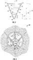
Figure 4 is a view of the different shaped charges firing in different directions with multiple focal points. - In the following description, certain terms have been used for brevity, clarity, and examples. No unnecessary limitations are to be implied therefrom and such terms are used for descriptive purposes only and are intended to be broadly construed. The different apparatus, systems and method steps described herein may be used alone or in combination with other apparatus, systems and method steps. It is to be expected that various equivalents, alternatives, and modifications are possible within the scope of the appended claims.
- Referring to
FIG. 1 , atypical perforating gun 10 comprises agun body 11 that houses the shapedcharges 12. Thegun body 11 containsend fittings 16 and 20 which secure thecharge tube 18 into place. Thecharge tube 18 has charge holes 23 that are openings where shapedcharges 12 may be placed. Thegun body 11 has threaded ends 14 that allow it to be connected to a series of perforatingguns 10 or to other downhole equipment depending on the job requirement. Other design variations may use ends that are bolted together, InFIG. 1 , a 60 degree phase gun is shown where each shapedcharge 12 is rotate about the center axis by 60 degrees from one shaped charge to the next. Other embodiments of this design are possible including zero degree phase guns, where all the shaped charges are aligned. Other end fittings or connections could be used in lieu of threaded fittings, such as bolted fittings. - Referring to
FIG. 2 , the shapedcharges 12 includes a shapedcharge case 28 that holds theexplosive material 26 and theliner 27. The shapedcharge case 12 typically is composed of alloy steel. Theliner 27 is usually composed of a powdered metal that is either pressed or stamped into place. The metals used inliner 27 include brass, copper, tungsten, and lead. - In this embodiment the
liner 27 andenergetic material 26 may be held in place by an adhesive, a snap ring, or some other retaining device. The shapedcharge 12 may also include vent holes 32 in order to assist in allowing gases to vent out of the shapedcharge 12 if an unplanned deflagration of theenergetic material 26 occurs. The detonating cord that initiates the shapedcharge 12 is placed adjacent toopening 25. - At least one embodiment of the invention includes a shaped charge comprising of a
case 12, anexplosive material 26, a shapedcharge liner 27 further comprising anaxis 45, afirst section 40 having a substantially conical shape, a firstinner surface 47, alowermost apex 48, a firstconical angle 49 respective to the firstinner surface 47, asecond section 42 having a substantially frusto-conical shape, a secondinner surface 50, a secondconical angle 51 respective to the secondinner surface 50, athird section 46 having a substantially frusto-conical shape, a thirdinner surface 52, atop surface 54 perpendicular to the axis, a thirdconical angle 53 respective to the thirdinner surface 52, wherein thefirst section 40,second section 42 andthird section 46 are axially aligned about theaxis 45. The secondconical angle 51 is larger than the firstconical angle 49 and the secondconical angle 49 is larger than the thirdconical angle 53. Theliner 27 has atotal height 55, wherein thetotal height 55 is measured from thelowermost apex 48 of thefirst section 40 along theaxis 45 to a plane perpendicular to the top surface. - According to the invention, the first
conical angle 49 is larger than or equal to the thirdconical angle 53. The embodiment may have a firstconical angle 49 between 44 and 52 degrees. The embodiment may have a secondconical angle 51 between 56 and 58 degrees. The embodiment may have a thirdconical angle 53 between 44 and 54 degrees. The embodiment of the invention has afirst angle break 43 where thefirst section 40 andsecond section 42 intersect. The embodiment of the invention has asecond angle break 44 where thesecond section 42 and thethird section 46 intersect. The embodiment of the invention has afirst height 57 measured along theaxis 45 from thelowermost apex 48 to a plane perpendicular to thefirst angle break 43. The embodiment of the invention has asecond height 56 measured along theaxis 45 from thelowermost apex 48 to a plane perpendicular to thesecond angle break 44. The embodiment may have thefirst height 57 being between 26 and 34 percent of thetotal height 55. The embodiment of the invention has thesecond height 56 being between 70 and 73 percent of thetotal height 55. - Referring to
FIG. 4 , at least one embodiment of the invention includes a method for perforating aformation 60 comprising placing a perforatinggun 61 downhole at a predetermined location of a casedhole 62 having aninner surface 63. Place a plurality of shapedcharges 64, in this example there six shown, in a plurality of orientations about the perforatinggun 61 using the liner configuration described herein. The embodiment includes detonating the plurality of shapedcharges 64 in a plurality of directions, with a plurality of fluid gaps. This embodiment, using the liner described herein, can perforate consistent diameter holes in thecase hole 63 at a plurality of fluid gaps. - The invention relies on the multiple focal points 66 of the
explosive jets 65 that results from the liner configurations disclosed herein. InFIG. 4 , there are six shapedcharges 64 shown at 60 degrees of phase with respect to each other. There are fourfluid gaps gun 61 of a 0.42 cm (3/18") size, decentralized in a 13.97 cm (5.5 inch) casing for a horizontal well results in afluid gap 67 of 0.51 cm (0.2"), afluid gap 68 of 1.27 cm (0.5"), afluid gap 69 of 3.05 cm (1.2"), and afluid gap 70 of 4.32 cm (1.7"). Therefore, each shapedcharge 64 must have at least four focal points 66, that converge at approximately the same distances as thefluid gaps - A variation of the embodiment may include the perforating
gun 61 being substantially cylindrical and located adjacent to theinner surface 63 of the casedhole 62. It may also include the perforatinggun 61 being decentralized with respect to a center axis of the casedhole 62 at the predetermined location. It may also comprise locating the plurality of shapedcharges 64 axially about the perforating gun at 60 degree angled intervals from each other. It may also further comprise penetrating theformation 60 between 73.66 and 111.76 cm (29 and 44) inches. In the alternative it may also further comprise the plurality of shapedcharges 64 penetrating theformation 60 between 88.9 and 96.52 cm (35 and 38 inches). In the alternative it may further comprise the plurality of shapedcharges 64 penetrating theformation 60 between 71.12 and 96.52 cm (28 and 38 inches). In the alternative it may further comprise the plurality of shapedcharges 64 penetrating theformation 60 between 76.2 and 91.44 cm (30 and 36 inches). In the alternative it may further comprise the plurality of shapedcharges 64 penetrating theformation 60 between 86.36 and 96.52 cm (34 and 38 inches). In the alternative it may further comprise the plurality of shapedcharges 64 penetrating theformation 60 between 43.18 and 86.36 cm (17 and 34 inches). The invention may include the consistent diameter holes being defined as each hole diameter having less than a 10 percent deviation from the average hole size of the plurality of the holes.
Claims (9)
- A shaped charge liner (27) comprising:an axis (45);a first section (40) having a substantially conical shape, a first inner surface (47), a lowermost apex (48), and a first conical angle (49) respective to the first inner surface (47);a second section (42) having a substantially frusto-conical shape, a second inner surface (50), and a second conical angle (51) respective to the second inner surface (50);a third section (46) having a substantially frusto-conical shape, a third inner surface (52), a top surface (54) perpendicular to the axis, and a third conical angle (53) respective to the third inner surface (52);wherein the first section (40), second section (42) and third section (46) are axially aligned about the axis (45), the second conical angle (51) is larger than the first conical angle (49) and the second conical angle (51) is larger than the third conical angle (53);a total height (55), wherein the total height (55) is measured from the apex (48) of the first section (40) along the axis (45) to a plane perpendicular to the top surface (54);a first angle break (43) where the first section (40) and second section (42) intersect;a second angle break (44) where the second section (42) and the third section (46) intersect;a first height (57) measured along the axis (45) from the lowermost apex (48) to a plane perpendicular to the first angle break (43) and having a second height (56) measured along the axis (45) from the lowermost apex (48) to a plane perpendicular to the second angle break (44);wherein the second height (56) is between 70 and 73 percent of the total height (55); andwherein the first conical angle (49) is larger than or equal to the third conical angle (53).
- The shaped charge liner (27) of claim 1, wherein the first conical angle (49) is between 44 and 52 degrees.
- The shaped charge liner (27) of claim 1, wherein the second conical angle (51) is between 56 and 58 degrees.
- The shaped charge liner (27) of claim 1, wherein the third conical angle (53) is between 44 and 54 degrees.
- The shaped charge liner (27) of claim 1, wherein the first height (57) is between 26 and 34 percent of the total height (55).
- A shaped charge (12; 64) comprising:a case (28);explosive material (26); anda shaped charge liner (27) according to any of the claims 1 to 5.
- A method for perforating a formation (60) comprising:placing a perforating gun (10; 61) downhole at a predetermined location of a cased hole (62) having an inner surface (63), placing a plurality of shaped charges (12; 64) according to claim 6 in a plurality of orientations about the perforating gun (10; 61);detonating a plurality of shaped charges (12; 64) in a plurality of directions, with a plurality of fluid gaps (67, 68, 69, 70); andperforating consistent diameter holes in the case hole (62) at a plurality of fluid gaps (67, 68, 69, 70).
- The method of claim 7, wherein the perforating gun (10; 61) is decentralized with respect to the cased hole (62) at the predetermined location.
- The method of claim 7, wherein consistent diameter holes is defined as each hole diameter having less than a 10 percent deviation from the average hole size of the plurality of the holes.
Priority Applications (2)
| Application Number | Priority Date | Filing Date | Title |
|---|---|---|---|
| PL15796704T PL3108201T3 (en) | 2014-05-21 | 2015-05-21 | Consistent entry hole shaped charge |
| EP20153288.4A EP3663702B1 (en) | 2014-05-21 | 2015-05-21 | Consistent entry hole shaped charge |
Applications Claiming Priority (2)
| Application Number | Priority Date | Filing Date | Title |
|---|---|---|---|
| US201462001324P | 2014-05-21 | 2014-05-21 | |
| PCT/US2015/032080 WO2015179713A1 (en) | 2014-05-21 | 2015-05-21 | Consistent entry hole shaped charge |
Related Child Applications (2)
| Application Number | Title | Priority Date | Filing Date |
|---|---|---|---|
| EP20153288.4A Division-Into EP3663702B1 (en) | 2014-05-21 | 2015-05-21 | Consistent entry hole shaped charge |
| EP20153288.4A Division EP3663702B1 (en) | 2014-05-21 | 2015-05-21 | Consistent entry hole shaped charge |
Publications (3)
| Publication Number | Publication Date |
|---|---|
| EP3108201A1 EP3108201A1 (en) | 2016-12-28 |
| EP3108201A4 EP3108201A4 (en) | 2017-11-15 |
| EP3108201B1 true EP3108201B1 (en) | 2020-02-26 |
Family
ID=54554803
Family Applications (2)
| Application Number | Title | Priority Date | Filing Date |
|---|---|---|---|
| EP15796704.3A Active EP3108201B1 (en) | 2014-05-21 | 2015-05-21 | Consistent entry hole shaped charge |
| EP20153288.4A Active EP3663702B1 (en) | 2014-05-21 | 2015-05-21 | Consistent entry hole shaped charge |
Family Applications After (1)
| Application Number | Title | Priority Date | Filing Date |
|---|---|---|---|
| EP20153288.4A Active EP3663702B1 (en) | 2014-05-21 | 2015-05-21 | Consistent entry hole shaped charge |
Country Status (5)
| Country | Link |
|---|---|
| US (2) | US10227851B2 (en) |
| EP (2) | EP3108201B1 (en) |
| CA (1) | CA2933225A1 (en) |
| PL (1) | PL3108201T3 (en) |
| WO (1) | WO2015179713A1 (en) |
Families Citing this family (34)
| Publication number | Priority date | Publication date | Assignee | Title |
|---|---|---|---|---|
| US11293736B2 (en) | 2015-03-18 | 2022-04-05 | DynaEnergetics Europe GmbH | Electrical connector |
| US9784549B2 (en) | 2015-03-18 | 2017-10-10 | Dynaenergetics Gmbh & Co. Kg | Bulkhead assembly having a pivotable electric contact component and integrated ground apparatus |
| US10753183B2 (en) | 2016-10-13 | 2020-08-25 | Geodynamics, Inc. | Refracturing in a multistring casing with constant entrance hole perforating gun system and method |
| US9725993B1 (en) | 2016-10-13 | 2017-08-08 | Geodynamics, Inc. | Constant entrance hole perforating gun system and method |
| CN106761599A (en) * | 2016-12-24 | 2017-05-31 | 中石化石油工程技术服务有限公司 | A kind of perforating bullet of raising duct flow conductivity |
| US11053782B2 (en) | 2018-04-06 | 2021-07-06 | DynaEnergetics Europe GmbH | Perforating gun system and method of use |
| US10458213B1 (en) | 2018-07-17 | 2019-10-29 | Dynaenergetics Gmbh & Co. Kg | Positioning device for shaped charges in a perforating gun module |
| US10386168B1 (en) | 2018-06-11 | 2019-08-20 | Dynaenergetics Gmbh & Co. Kg | Conductive detonating cord for perforating gun |
| WO2019245569A1 (en) | 2018-06-21 | 2019-12-26 | Halliburton Energy Services, Inc. | Shaped charge with tri-radii liner for oilfield perforating |
| US11078763B2 (en) | 2018-08-10 | 2021-08-03 | Gr Energy Services Management, Lp | Downhole perforating tool with integrated detonation assembly and method of using same |
| US10858919B2 (en) | 2018-08-10 | 2020-12-08 | Gr Energy Services Management, Lp | Quick-locking detonation assembly of a downhole perforating tool and method of using same |
| US11994008B2 (en) | 2018-08-10 | 2024-05-28 | Gr Energy Services Management, Lp | Loaded perforating gun with plunging charge assembly and method of using same |
| USD1034879S1 (en) | 2019-02-11 | 2024-07-09 | DynaEnergetics Europe GmbH | Gun body |
| USD1010758S1 (en) | 2019-02-11 | 2024-01-09 | DynaEnergetics Europe GmbH | Gun body |
| USD1019709S1 (en) | 2019-02-11 | 2024-03-26 | DynaEnergetics Europe GmbH | Charge holder |
| US11976543B2 (en) * | 2019-03-19 | 2024-05-07 | Indian Institute Of Technology, Madras | High energy fracking device for focused shock wave generation for oil and gas recovery applications |
| CN113950607A (en) * | 2019-06-12 | 2022-01-18 | 狩猎巨人公司 | Triangular shaped charge liner with jet former |
| WO2020249744A2 (en) | 2019-06-14 | 2020-12-17 | DynaEnergetics Europe GmbH | Perforating gun assembly with rotating shaped charge holder |
| WO2021122797A1 (en) | 2019-12-17 | 2021-06-24 | DynaEnergetics Europe GmbH | Modular perforating gun system |
| US12084962B2 (en) | 2020-03-16 | 2024-09-10 | DynaEnergetics Europe GmbH | Tandem seal adapter with integrated tracer material |
| USD904475S1 (en) | 2020-04-29 | 2020-12-08 | DynaEnergetics Europe GmbH | Tandem sub |
| USD908754S1 (en) | 2020-04-30 | 2021-01-26 | DynaEnergetics Europe GmbH | Tandem sub |
| WO2022122742A2 (en) * | 2020-12-09 | 2022-06-16 | DynaEnergetics Europe GmbH | Equal entry hole perforating gun system with position optimized shaped charges |
| NO20230794A1 (en) | 2020-12-21 | 2023-07-17 | DynaEnergetics Europe GmbH | Encapsulated shaped charge |
| WO2022148557A1 (en) | 2021-01-08 | 2022-07-14 | DynaEnergetics Europe GmbH | Perforating gun assembly and components |
| US11499401B2 (en) | 2021-02-04 | 2022-11-15 | DynaEnergetics Europe GmbH | Perforating gun assembly with performance optimized shaped charge load |
| WO2022167297A1 (en) | 2021-02-04 | 2022-08-11 | DynaEnergetics Europe GmbH | Perforating gun assembly with performance optimized shaped charge load |
| US11732556B2 (en) | 2021-03-03 | 2023-08-22 | DynaEnergetics Europe GmbH | Orienting perforation gun assembly |
| WO2022192541A1 (en) * | 2021-03-12 | 2022-09-15 | Schlumberger Technology Corporation | Shaped charge integrated canister |
| US12000267B2 (en) | 2021-09-24 | 2024-06-04 | DynaEnergetics Europe GmbH | Communication and location system for an autonomous frack system |
| US12253339B2 (en) | 2021-10-25 | 2025-03-18 | DynaEnergetics Europe GmbH | Adapter and shaped charge apparatus for optimized perforation jet |
| US12312925B2 (en) | 2021-12-22 | 2025-05-27 | DynaEnergetics Europe GmbH | Manually oriented internal shaped charge alignment system and method of use |
| US11965719B2 (en) * | 2022-05-10 | 2024-04-23 | Halliburton Energy Services, Inc. | Segment pressing of shaped charge powder metal liners |
| CN117328843A (en) * | 2023-12-01 | 2024-01-02 | 大庆金祥寓科技有限公司 | Oil pipe conveying type precise secondary perforating device and working method thereof |
Family Cites Families (8)
| Publication number | Priority date | Publication date | Assignee | Title |
|---|---|---|---|---|
| FR1022472A (en) * | 1950-07-25 | 1953-03-05 | Soc Tech De Rech Ind | Improvements to shaped charges for explosive devices |
| US2856850A (en) | 1954-03-22 | 1958-10-21 | Joseph H Church | Shaped charge |
| FR2488389B1 (en) * | 1980-08-06 | 1986-04-25 | Serat | IMPROVEMENTS ON HOLLOW CHARGES |
| FR2569473B1 (en) | 1984-08-21 | 1987-10-23 | Realisa Applic Techni Et | IMPROVEMENTS TO HOLLOW CHARGES |
| US6591911B1 (en) * | 1999-07-22 | 2003-07-15 | Schlumberger Technology Corporation | Multi-directional gun carrier method and apparatus |
| US6840178B2 (en) * | 2003-02-21 | 2005-01-11 | Titan Specialties, Ltd. | Shaped charge liner |
| US8167044B2 (en) * | 2009-12-16 | 2012-05-01 | Sclumberger Technology Corporation | Shaped charge |
| US9291435B2 (en) * | 2013-12-31 | 2016-03-22 | The United States Of America As Represented By The Secretary Of The Navy | Shaped charge including structures and compositions having lower explosive charge to liner mass ratio |
-
2015
- 2015-05-21 CA CA2933225A patent/CA2933225A1/en not_active Abandoned
- 2015-05-21 PL PL15796704T patent/PL3108201T3/en unknown
- 2015-05-21 EP EP15796704.3A patent/EP3108201B1/en active Active
- 2015-05-21 WO PCT/US2015/032080 patent/WO2015179713A1/en not_active Ceased
- 2015-05-21 US US15/313,041 patent/US10227851B2/en active Active
- 2015-05-21 EP EP20153288.4A patent/EP3663702B1/en active Active
-
2019
- 2019-01-30 US US16/262,627 patent/US10458212B2/en active Active
Non-Patent Citations (1)
| Title |
|---|
| None * |
Also Published As
| Publication number | Publication date |
|---|---|
| EP3108201A1 (en) | 2016-12-28 |
| US20190162055A1 (en) | 2019-05-30 |
| EP3663702B1 (en) | 2023-08-23 |
| EP3663702C0 (en) | 2023-08-23 |
| US10227851B2 (en) | 2019-03-12 |
| PL3108201T3 (en) | 2020-06-29 |
| US10458212B2 (en) | 2019-10-29 |
| EP3108201A4 (en) | 2017-11-15 |
| US20170199016A1 (en) | 2017-07-13 |
| EP3663702A1 (en) | 2020-06-10 |
| CA2933225A1 (en) | 2015-11-26 |
| WO2015179713A1 (en) | 2015-11-26 |
Similar Documents
| Publication | Publication Date | Title |
|---|---|---|
| US10458212B2 (en) | Consistent entry hole shaped charge | |
| US9951589B2 (en) | Low angle bottom circulator shaped charge | |
| US10422204B2 (en) | System and method for perforating a wellbore | |
| EP3108097B1 (en) | Zinc one piece link system | |
| EP3108092B1 (en) | Alignment system for a perforating gun | |
| EP3278052B1 (en) | Snap-on liner retention device | |
| US10851624B2 (en) | Perforating gun assembly and methods of use | |
| US11629585B2 (en) | Integrated coaxial perforating acidizing operation | |
| US11933148B2 (en) | Tri-angled liner with jet shaper | |
| US11261711B2 (en) | Crimped attachment of end fitting to charge tube | |
| CA3126028C (en) | Integrated coaxial perforating acidizing operation | |
| WO2022122742A2 (en) | Equal entry hole perforating gun system with position optimized shaped charges |
Legal Events
| Date | Code | Title | Description |
|---|---|---|---|
| PUAI | Public reference made under article 153(3) epc to a published international application that has entered the european phase |
Free format text: ORIGINAL CODE: 0009012 |
|
| STAA | Information on the status of an ep patent application or granted ep patent |
Free format text: STATUS: REQUEST FOR EXAMINATION WAS MADE |
|
| 17P | Request for examination filed |
Effective date: 20160920 |
|
| AK | Designated contracting states |
Kind code of ref document: A1 Designated state(s): AL AT BE BG CH CY CZ DE DK EE ES FI FR GB GR HR HU IE IS IT LI LT LU LV MC MK MT NL NO PL PT RO RS SE SI SK SM TR |
|
| AX | Request for extension of the european patent |
Extension state: BA ME |
|
| DAV | Request for validation of the european patent (deleted) | ||
| DAX | Request for extension of the european patent (deleted) | ||
| A4 | Supplementary search report drawn up and despatched |
Effective date: 20171018 |
|
| RIC1 | Information provided on ipc code assigned before grant |
Ipc: E21B 43/117 20060101ALI20171012BHEP Ipc: F42B 12/00 20060101AFI20171012BHEP Ipc: F42B 1/028 20060101ALI20171012BHEP |
|
| STAA | Information on the status of an ep patent application or granted ep patent |
Free format text: STATUS: EXAMINATION IS IN PROGRESS |
|
| 17Q | First examination report despatched |
Effective date: 20181004 |
|
| GRAP | Despatch of communication of intention to grant a patent |
Free format text: ORIGINAL CODE: EPIDOSNIGR1 |
|
| STAA | Information on the status of an ep patent application or granted ep patent |
Free format text: STATUS: GRANT OF PATENT IS INTENDED |
|
| INTG | Intention to grant announced |
Effective date: 20190918 |
|
| RIN1 | Information on inventor provided before grant (corrected) |
Inventor name: COLLINS, WILLIAM, R. Inventor name: PEDERSON, MARK, A. |
|
| GRAS | Grant fee paid |
Free format text: ORIGINAL CODE: EPIDOSNIGR3 |
|
| GRAA | (expected) grant |
Free format text: ORIGINAL CODE: 0009210 |
|
| STAA | Information on the status of an ep patent application or granted ep patent |
Free format text: STATUS: THE PATENT HAS BEEN GRANTED |
|
| RAP1 | Party data changed (applicant data changed or rights of an application transferred) |
Owner name: HUNTING TITAN, INC. |
|
| AK | Designated contracting states |
Kind code of ref document: B1 Designated state(s): AL AT BE BG CH CY CZ DE DK EE ES FI FR GB GR HR HU IE IS IT LI LT LU LV MC MK MT NL NO PL PT RO RS SE SI SK SM TR |
|
| REG | Reference to a national code |
Ref country code: GB Ref legal event code: FG4D |
|
| REG | Reference to a national code |
Ref country code: CH Ref legal event code: EP |
|
| REG | Reference to a national code |
Ref country code: AT Ref legal event code: REF Ref document number: 1238163 Country of ref document: AT Kind code of ref document: T Effective date: 20200315 |
|
| REG | Reference to a national code |
Ref country code: IE Ref legal event code: FG4D |
|
| REG | Reference to a national code |
Ref country code: DE Ref legal event code: R096 Ref document number: 602015047797 Country of ref document: DE |
|
| REG | Reference to a national code |
Ref country code: SE Ref legal event code: TRGR |
|
| REG | Reference to a national code |
Ref country code: NL Ref legal event code: FP |
|
| REG | Reference to a national code |
Ref country code: NO Ref legal event code: T2 Effective date: 20200226 |
|
| PG25 | Lapsed in a contracting state [announced via postgrant information from national office to epo] |
Ref country code: RS Free format text: LAPSE BECAUSE OF FAILURE TO SUBMIT A TRANSLATION OF THE DESCRIPTION OR TO PAY THE FEE WITHIN THE PRESCRIBED TIME-LIMIT Effective date: 20200226 Ref country code: FI Free format text: LAPSE BECAUSE OF FAILURE TO SUBMIT A TRANSLATION OF THE DESCRIPTION OR TO PAY THE FEE WITHIN THE PRESCRIBED TIME-LIMIT Effective date: 20200226 |
|
| REG | Reference to a national code |
Ref country code: LT Ref legal event code: MG4D |
|
| PG25 | Lapsed in a contracting state [announced via postgrant information from national office to epo] |
Ref country code: BG Free format text: LAPSE BECAUSE OF FAILURE TO SUBMIT A TRANSLATION OF THE DESCRIPTION OR TO PAY THE FEE WITHIN THE PRESCRIBED TIME-LIMIT Effective date: 20200526 Ref country code: IS Free format text: LAPSE BECAUSE OF FAILURE TO SUBMIT A TRANSLATION OF THE DESCRIPTION OR TO PAY THE FEE WITHIN THE PRESCRIBED TIME-LIMIT Effective date: 20200626 Ref country code: GR Free format text: LAPSE BECAUSE OF FAILURE TO SUBMIT A TRANSLATION OF THE DESCRIPTION OR TO PAY THE FEE WITHIN THE PRESCRIBED TIME-LIMIT Effective date: 20200527 Ref country code: LV Free format text: LAPSE BECAUSE OF FAILURE TO SUBMIT A TRANSLATION OF THE DESCRIPTION OR TO PAY THE FEE WITHIN THE PRESCRIBED TIME-LIMIT Effective date: 20200226 Ref country code: HR Free format text: LAPSE BECAUSE OF FAILURE TO SUBMIT A TRANSLATION OF THE DESCRIPTION OR TO PAY THE FEE WITHIN THE PRESCRIBED TIME-LIMIT Effective date: 20200226 |
|
| PGFP | Annual fee paid to national office [announced via postgrant information from national office to epo] |
Ref country code: PL Payment date: 20200515 Year of fee payment: 6 Ref country code: SE Payment date: 20200526 Year of fee payment: 6 |
|
| PG25 | Lapsed in a contracting state [announced via postgrant information from national office to epo] |
Ref country code: ES Free format text: LAPSE BECAUSE OF FAILURE TO SUBMIT A TRANSLATION OF THE DESCRIPTION OR TO PAY THE FEE WITHIN THE PRESCRIBED TIME-LIMIT Effective date: 20200226 Ref country code: PT Free format text: LAPSE BECAUSE OF FAILURE TO SUBMIT A TRANSLATION OF THE DESCRIPTION OR TO PAY THE FEE WITHIN THE PRESCRIBED TIME-LIMIT Effective date: 20200719 Ref country code: DK Free format text: LAPSE BECAUSE OF FAILURE TO SUBMIT A TRANSLATION OF THE DESCRIPTION OR TO PAY THE FEE WITHIN THE PRESCRIBED TIME-LIMIT Effective date: 20200226 Ref country code: SK Free format text: LAPSE BECAUSE OF FAILURE TO SUBMIT A TRANSLATION OF THE DESCRIPTION OR TO PAY THE FEE WITHIN THE PRESCRIBED TIME-LIMIT Effective date: 20200226 Ref country code: LT Free format text: LAPSE BECAUSE OF FAILURE TO SUBMIT A TRANSLATION OF THE DESCRIPTION OR TO PAY THE FEE WITHIN THE PRESCRIBED TIME-LIMIT Effective date: 20200226 Ref country code: EE Free format text: LAPSE BECAUSE OF FAILURE TO SUBMIT A TRANSLATION OF THE DESCRIPTION OR TO PAY THE FEE WITHIN THE PRESCRIBED TIME-LIMIT Effective date: 20200226 Ref country code: CZ Free format text: LAPSE BECAUSE OF FAILURE TO SUBMIT A TRANSLATION OF THE DESCRIPTION OR TO PAY THE FEE WITHIN THE PRESCRIBED TIME-LIMIT Effective date: 20200226 Ref country code: RO Free format text: LAPSE BECAUSE OF FAILURE TO SUBMIT A TRANSLATION OF THE DESCRIPTION OR TO PAY THE FEE WITHIN THE PRESCRIBED TIME-LIMIT Effective date: 20200226 Ref country code: SM Free format text: LAPSE BECAUSE OF FAILURE TO SUBMIT A TRANSLATION OF THE DESCRIPTION OR TO PAY THE FEE WITHIN THE PRESCRIBED TIME-LIMIT Effective date: 20200226 |
|
| REG | Reference to a national code |
Ref country code: AT Ref legal event code: MK05 Ref document number: 1238163 Country of ref document: AT Kind code of ref document: T Effective date: 20200226 |
|
| REG | Reference to a national code |
Ref country code: DE Ref legal event code: R097 Ref document number: 602015047797 Country of ref document: DE |
|
| PLBE | No opposition filed within time limit |
Free format text: ORIGINAL CODE: 0009261 |
|
| STAA | Information on the status of an ep patent application or granted ep patent |
Free format text: STATUS: NO OPPOSITION FILED WITHIN TIME LIMIT |
|
| PG25 | Lapsed in a contracting state [announced via postgrant information from national office to epo] |
Ref country code: IT Free format text: LAPSE BECAUSE OF FAILURE TO SUBMIT A TRANSLATION OF THE DESCRIPTION OR TO PAY THE FEE WITHIN THE PRESCRIBED TIME-LIMIT Effective date: 20200226 Ref country code: LI Free format text: LAPSE BECAUSE OF NON-PAYMENT OF DUE FEES Effective date: 20200531 Ref country code: CH Free format text: LAPSE BECAUSE OF NON-PAYMENT OF DUE FEES Effective date: 20200531 Ref country code: MC Free format text: LAPSE BECAUSE OF FAILURE TO SUBMIT A TRANSLATION OF THE DESCRIPTION OR TO PAY THE FEE WITHIN THE PRESCRIBED TIME-LIMIT Effective date: 20200226 Ref country code: AT Free format text: LAPSE BECAUSE OF FAILURE TO SUBMIT A TRANSLATION OF THE DESCRIPTION OR TO PAY THE FEE WITHIN THE PRESCRIBED TIME-LIMIT Effective date: 20200226 |
|
| 26N | No opposition filed |
Effective date: 20201127 |
|
| PG25 | Lapsed in a contracting state [announced via postgrant information from national office to epo] |
Ref country code: SI Free format text: LAPSE BECAUSE OF FAILURE TO SUBMIT A TRANSLATION OF THE DESCRIPTION OR TO PAY THE FEE WITHIN THE PRESCRIBED TIME-LIMIT Effective date: 20200226 |
|
| REG | Reference to a national code |
Ref country code: BE Ref legal event code: MM Effective date: 20200531 |
|
| PG25 | Lapsed in a contracting state [announced via postgrant information from national office to epo] |
Ref country code: LU Free format text: LAPSE BECAUSE OF NON-PAYMENT OF DUE FEES Effective date: 20200521 |
|
| PG25 | Lapsed in a contracting state [announced via postgrant information from national office to epo] |
Ref country code: IE Free format text: LAPSE BECAUSE OF NON-PAYMENT OF DUE FEES Effective date: 20200521 |
|
| PG25 | Lapsed in a contracting state [announced via postgrant information from national office to epo] |
Ref country code: BE Free format text: LAPSE BECAUSE OF NON-PAYMENT OF DUE FEES Effective date: 20200531 |
|
| REG | Reference to a national code |
Ref country code: SE Ref legal event code: EUG |
|
| PG25 | Lapsed in a contracting state [announced via postgrant information from national office to epo] |
Ref country code: SE Free format text: LAPSE BECAUSE OF NON-PAYMENT OF DUE FEES Effective date: 20210522 |
|
| PG25 | Lapsed in a contracting state [announced via postgrant information from national office to epo] |
Ref country code: TR Free format text: LAPSE BECAUSE OF FAILURE TO SUBMIT A TRANSLATION OF THE DESCRIPTION OR TO PAY THE FEE WITHIN THE PRESCRIBED TIME-LIMIT Effective date: 20200226 Ref country code: MT Free format text: LAPSE BECAUSE OF FAILURE TO SUBMIT A TRANSLATION OF THE DESCRIPTION OR TO PAY THE FEE WITHIN THE PRESCRIBED TIME-LIMIT Effective date: 20200226 Ref country code: CY Free format text: LAPSE BECAUSE OF FAILURE TO SUBMIT A TRANSLATION OF THE DESCRIPTION OR TO PAY THE FEE WITHIN THE PRESCRIBED TIME-LIMIT Effective date: 20200226 |
|
| PG25 | Lapsed in a contracting state [announced via postgrant information from national office to epo] |
Ref country code: MK Free format text: LAPSE BECAUSE OF FAILURE TO SUBMIT A TRANSLATION OF THE DESCRIPTION OR TO PAY THE FEE WITHIN THE PRESCRIBED TIME-LIMIT Effective date: 20200226 Ref country code: AL Free format text: LAPSE BECAUSE OF FAILURE TO SUBMIT A TRANSLATION OF THE DESCRIPTION OR TO PAY THE FEE WITHIN THE PRESCRIBED TIME-LIMIT Effective date: 20200226 |
|
| PG25 | Lapsed in a contracting state [announced via postgrant information from national office to epo] |
Ref country code: PL Free format text: LAPSE BECAUSE OF NON-PAYMENT OF DUE FEES Effective date: 20210521 |
|
| PGFP | Annual fee paid to national office [announced via postgrant information from national office to epo] |
Ref country code: NO Payment date: 20230519 Year of fee payment: 9 Ref country code: NL Payment date: 20230525 Year of fee payment: 9 Ref country code: DE Payment date: 20230530 Year of fee payment: 9 |
|
| PGFP | Annual fee paid to national office [announced via postgrant information from national office to epo] |
Ref country code: GB Payment date: 20230523 Year of fee payment: 9 |
|
| PGFP | Annual fee paid to national office [announced via postgrant information from national office to epo] |
Ref country code: FR Payment date: 20240527 Year of fee payment: 10 |
|
| REG | Reference to a national code |
Ref country code: NL Ref legal event code: MM Effective date: 20240601 |
|
| PG25 | Lapsed in a contracting state [announced via postgrant information from national office to epo] |
Ref country code: NO Free format text: LAPSE BECAUSE OF NON-PAYMENT OF DUE FEES Effective date: 20240531 |
|
| GBPC | Gb: european patent ceased through non-payment of renewal fee |
Effective date: 20240521 |
|
| PG25 | Lapsed in a contracting state [announced via postgrant information from national office to epo] |
Ref country code: NO Free format text: LAPSE BECAUSE OF NON-PAYMENT OF DUE FEES Effective date: 20240531 |
|
| PG25 | Lapsed in a contracting state [announced via postgrant information from national office to epo] |
Ref country code: NL Free format text: LAPSE BECAUSE OF NON-PAYMENT OF DUE FEES Effective date: 20240601 |
|
| PG25 | Lapsed in a contracting state [announced via postgrant information from national office to epo] |
Ref country code: GB Free format text: LAPSE BECAUSE OF NON-PAYMENT OF DUE FEES Effective date: 20240521 |
|
| REG | Reference to a national code |
Ref country code: DE Ref legal event code: R119 Ref document number: 602015047797 Country of ref document: DE |
|
| PG25 | Lapsed in a contracting state [announced via postgrant information from national office to epo] |
Ref country code: DE Free format text: LAPSE BECAUSE OF NON-PAYMENT OF DUE FEES Effective date: 20251202 |
|
| PG25 | Lapsed in a contracting state [announced via postgrant information from national office to epo] |
Ref country code: FR Free format text: LAPSE BECAUSE OF NON-PAYMENT OF DUE FEES Effective date: 20250531 |