EP3107679B1 - Cutting method - Google Patents
Cutting method Download PDFInfo
- Publication number
- EP3107679B1 EP3107679B1 EP14836976.2A EP14836976A EP3107679B1 EP 3107679 B1 EP3107679 B1 EP 3107679B1 EP 14836976 A EP14836976 A EP 14836976A EP 3107679 B1 EP3107679 B1 EP 3107679B1
- Authority
- EP
- European Patent Office
- Prior art keywords
- cutting
- cutting line
- sheet material
- electrodes
- intersection point
- Prior art date
- Legal status (The legal status is an assumption and is not a legal conclusion. Google has not performed a legal analysis and makes no representation as to the accuracy of the status listed.)
- Not-in-force
Links
Images

Classifications
-
- B—PERFORMING OPERATIONS; TRANSPORTING
- B23—MACHINE TOOLS; METAL-WORKING NOT OTHERWISE PROVIDED FOR
- B23K—SOLDERING OR UNSOLDERING; WELDING; CLADDING OR PLATING BY SOLDERING OR WELDING; CUTTING BY APPLYING HEAT LOCALLY, e.g. FLAME CUTTING; WORKING BY LASER BEAM
- B23K26/00—Working by laser beam, e.g. welding, cutting or boring
- B23K26/36—Removing material
- B23K26/38—Removing material by boring or cutting
-
- B—PERFORMING OPERATIONS; TRANSPORTING
- B23—MACHINE TOOLS; METAL-WORKING NOT OTHERWISE PROVIDED FOR
- B23K—SOLDERING OR UNSOLDERING; WELDING; CLADDING OR PLATING BY SOLDERING OR WELDING; CUTTING BY APPLYING HEAT LOCALLY, e.g. FLAME CUTTING; WORKING BY LASER BEAM
- B23K26/00—Working by laser beam, e.g. welding, cutting or boring
- B23K26/08—Devices involving relative movement between laser beam and workpiece
- B23K26/083—Devices involving movement of the workpiece in at least one axial direction
- B23K26/0838—Devices involving movement of the workpiece in at least one axial direction by using an endless conveyor belt
- B23K26/0846—Devices involving movement of the workpiece in at least one axial direction by using an endless conveyor belt for moving elongated workpieces longitudinally, e.g. wire or strip material
-
- B—PERFORMING OPERATIONS; TRANSPORTING
- B23—MACHINE TOOLS; METAL-WORKING NOT OTHERWISE PROVIDED FOR
- B23K—SOLDERING OR UNSOLDERING; WELDING; CLADDING OR PLATING BY SOLDERING OR WELDING; CUTTING BY APPLYING HEAT LOCALLY, e.g. FLAME CUTTING; WORKING BY LASER BEAM
- B23K26/00—Working by laser beam, e.g. welding, cutting or boring
- B23K26/36—Removing material
- B23K26/40—Removing material taking account of the properties of the material involved
- B23K26/402—Removing material taking account of the properties of the material involved involving non-metallic material, e.g. isolators
-
- H—ELECTRICITY
- H01—ELECTRIC ELEMENTS
- H01M—PROCESSES OR MEANS, e.g. BATTERIES, FOR THE DIRECT CONVERSION OF CHEMICAL ENERGY INTO ELECTRICAL ENERGY
- H01M50/00—Constructional details or processes of manufacture of the non-active parts of electrochemical cells other than fuel cells, e.g. hybrid cells
- H01M50/40—Separators; Membranes; Diaphragms; Spacing elements inside cells
- H01M50/403—Manufacturing processes of separators, membranes or diaphragms
- H01M50/406—Moulding; Embossing; Cutting
-
- H—ELECTRICITY
- H01—ELECTRIC ELEMENTS
- H01M—PROCESSES OR MEANS, e.g. BATTERIES, FOR THE DIRECT CONVERSION OF CHEMICAL ENERGY INTO ELECTRICAL ENERGY
- H01M50/00—Constructional details or processes of manufacture of the non-active parts of electrochemical cells other than fuel cells, e.g. hybrid cells
- H01M50/40—Separators; Membranes; Diaphragms; Spacing elements inside cells
- H01M50/409—Separators, membranes or diaphragms characterised by the material
- H01M50/446—Composite material consisting of a mixture of organic and inorganic materials
-
- H—ELECTRICITY
- H01—ELECTRIC ELEMENTS
- H01M—PROCESSES OR MEANS, e.g. BATTERIES, FOR THE DIRECT CONVERSION OF CHEMICAL ENERGY INTO ELECTRICAL ENERGY
- H01M50/00—Constructional details or processes of manufacture of the non-active parts of electrochemical cells other than fuel cells, e.g. hybrid cells
- H01M50/40—Separators; Membranes; Diaphragms; Spacing elements inside cells
- H01M50/46—Separators, membranes or diaphragms characterised by their combination with electrodes
- H01M50/461—Separators, membranes or diaphragms characterised by their combination with electrodes with adhesive layers between electrodes and separators
-
- H—ELECTRICITY
- H01—ELECTRIC ELEMENTS
- H01M—PROCESSES OR MEANS, e.g. BATTERIES, FOR THE DIRECT CONVERSION OF CHEMICAL ENERGY INTO ELECTRICAL ENERGY
- H01M50/00—Constructional details or processes of manufacture of the non-active parts of electrochemical cells other than fuel cells, e.g. hybrid cells
- H01M50/40—Separators; Membranes; Diaphragms; Spacing elements inside cells
- H01M50/463—Separators, membranes or diaphragms characterised by their shape
-
- B—PERFORMING OPERATIONS; TRANSPORTING
- B23—MACHINE TOOLS; METAL-WORKING NOT OTHERWISE PROVIDED FOR
- B23K—SOLDERING OR UNSOLDERING; WELDING; CLADDING OR PLATING BY SOLDERING OR WELDING; CUTTING BY APPLYING HEAT LOCALLY, e.g. FLAME CUTTING; WORKING BY LASER BEAM
- B23K2103/00—Materials to be soldered, welded or cut
- B23K2103/30—Organic materials
- B23K2103/42—Plastics other than composite materials
-
- B—PERFORMING OPERATIONS; TRANSPORTING
- B23—MACHINE TOOLS; METAL-WORKING NOT OTHERWISE PROVIDED FOR
- B23K—SOLDERING OR UNSOLDERING; WELDING; CLADDING OR PLATING BY SOLDERING OR WELDING; CUTTING BY APPLYING HEAT LOCALLY, e.g. FLAME CUTTING; WORKING BY LASER BEAM
- B23K2103/00—Materials to be soldered, welded or cut
- B23K2103/50—Inorganic materials other than metals or composite materials
-
- Y—GENERAL TAGGING OF NEW TECHNOLOGICAL DEVELOPMENTS; GENERAL TAGGING OF CROSS-SECTIONAL TECHNOLOGIES SPANNING OVER SEVERAL SECTIONS OF THE IPC; TECHNICAL SUBJECTS COVERED BY FORMER USPC CROSS-REFERENCE ART COLLECTIONS [XRACs] AND DIGESTS
- Y02—TECHNOLOGIES OR APPLICATIONS FOR MITIGATION OR ADAPTATION AGAINST CLIMATE CHANGE
- Y02E—REDUCTION OF GREENHOUSE GAS [GHG] EMISSIONS, RELATED TO ENERGY GENERATION, TRANSMISSION OR DISTRIBUTION
- Y02E60/00—Enabling technologies; Technologies with a potential or indirect contribution to GHG emissions mitigation
- Y02E60/10—Energy storage using batteries
Definitions
- the invention relates to a cutting method, in particular for cutting a sheet material that is usable as a separator for electrodes in an electric energy storage device, for example, a battery or a storage unit.
- the invention can be used to form elements (cells) of non-rectangular shape intended to be part of an electric energy storage device.
- Patent publication JP 2013119095A shows a solid state laser cutting apparatus for cutting the sheet of a separator of a secondary electrolytic battery by a straight cutting line executed in the space between two rectangular electrodes.
- One object of the invention is to provide a cutting method and/or apparatus for cutting the separator sheet material comprised between two electrodes.
- One advantage is enabling a non-straight cut to be made that is precise and effective.
- One advantage is to enable high quality cells to be made with electrodes of non-rectangular shape.
- One advantage is to obtain a clean and clear cut, in particular without wires or fragments of material that by remaining attached to a cut edge can make the cut imperfect and unable to detach the cut edges completely.
- One advantage is to avoid excessive deformation or other damage to the material, in particular along the cut edge.
- One advantage is to permit fast and efficient cutting.
- One advantage is to provide a cheap and simple method and/or apparatus.
- a cutting method comprises the step of providing an arrangement of non-rectangular electrodes arranged in a row on a separator sheet material, and the subsequent step of cutting the sheet material by executing a first cutting line with at least one movable laser beam, this first cutting line being then intersected by a second cutting line made with at least one movable beam according to an intersection direction that is transverse to the edge cut by the first cutting line at the intersection point.
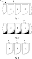
- Electrodes E may be arranged, as in this embodiment, in a row one after the other aligned in a longitudinal direction, leaving a certain space (for example constant) between one electrode and another. Cutting the sheet material S in the space comprised between each pair of consecutive electrodes E of the row may thus be permitted.
- dashed lines represent the cutting lines (which are transverse to the aforesaid longitudinal direction) between the pairs of consecutive electrodes, whereas continuous lines represent the areas of material intended for rejection.
- dashed lines represent the cutting lines (which are transverse to the aforesaid longitudinal direction) between the pairs of consecutive electrodes, whereas continuous lines represent the areas of material intended for rejection.
- dashed lines represent the cutting lines (which are transverse to the aforesaid longitudinal direction) between the pairs of consecutive electrodes, whereas continuous lines represent the areas of material intended for rejection.
- dashed lines represent the cutting lines (which are transverse to the aforesaid longitudinal direction) between the pairs of consecutive electrodes, whereas continuous lines represent the areas of material intended for rejection.
- FIG 3 the cells are shown after cutting and elimination of the offcuts.
- the sheet material S may comprise a web extending continuously along the aforesaid longitudinal direction.
- the arrangement 1 of electrodes may be made in a known manner and not disclosed here. In particular the arrangement 1 of electrodes may be conveyed in an advancement direction F parallel to the aforesaid longitudinal direction ( figure 9 ).
- the sheet material S may be bounded laterally by a first longitudinal side (for example right side) and by a second longitudinal side (for example left side) opposite the first longitudinal side. The two opposite longitudinal sides may be straight.
- the electrodes E arranged on the sheet material S may comprise, as in this embodiment, electrodes of non-rectangular shape.
- electrodes of non-rectangular shape In the attached figures a specific example of a non-rectangular electrode is shown. It is nevertheless possible to provide a multiplicity of different shapes of electrode (in particular non-rectangular).
- the electrodes E may be applied to the sheet material S so as to be attached thereto.
- a cutting method comprising the step of cutting with laser means, in particular with laser means of solid state type, the sheet material S of a separator for electrodes.
- the cut may be made, in particular, in the space between two consecutive electrodes E.
- the laser means is arranged for emitting at least one laser beam that is able to perform at least one cutting movement with at least one non-straight movement part.
- the cut may be used, as in this embodiment, to form single cells intended to produce an electric energy storage device.
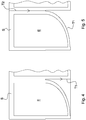
- the sheet material S of a separator for electrodes may be cut along at least two distinct cutting lines in which a first cutting line T1 is intersected by a second cutting line T2 with an intersecting direction that is transverse to the first cutting line T1 at the intersection point.
- the laser means may comprise means for emitting at least two laser beams that are able to perform cutting movements corresponding to the aforesaid cutting lines T1 and T2.
- the execution directions of the two cutting lines T1 and T2 have been indicated with arrows.
- the cut may also be executed in the direction opposite the direction indicated by the arrows.
- intersection direction may be, as in this case, perpendicular to the first cutting line T1 at the intersection point.
- the second cutting line T2 may be executed, as in the example, after the first cutting line T1 (at least at the intersection point).
- the intersection point may be, in particular, an intermediate point of the first cutting line T1.
- Both the aforesaid cutting lines T1 and T2 may be executed in the zone comprised between two non-rectangular electrodes E applied to the continuous sheet material S.
- the second cutting line T2 may continue beyond the intersection point (for example by a few millimetres or by a few tenths of a millimetre) with the first cutting line T1 (with the line T2 executed after the line T1 or, vice versa, with the line T2 which is executed before the line T1 and which continues beyond the point intended for the intersection) to ensure the detachment of the material at the intersection point (so as to separate the sheet into two distinct parts).
- the sheet material S may comprise, for example, two, three or more superimposed films.
- the electrodes E may be, for example, laminated between two superimposed films of separator material. It is possible that after lamination in the cutting zone an air gap forms that is comprised between the two superimposed films.
- the cutting step may comprise (simultaneous) cutting of the two superimposed films in the cutting zone where the air gap has formed. Solid state type laser cutting enables a clear and precise cut to be made even in the presence of an air gap.
- Executing of the first cutting line T1 may start and/or end on the first side of the sheet material S.
- the start and/or the end of the first cutting line T1 may be, as in this embodiment, transverse (perpendicular) to the side of the sheet material S.
- the second cutting line T2 may be executed between the second side of the sheet material S and an intermediate point of the first cutting line T1, for example starting in the second side of the sheet material S and ending at the intermediate point of the first cutting line T1.
- the first cutting line T1 may comprise at least one intermediate portion 2 provided with at least one component parallel to the aforesaid longitudinal direction.
- the intersection point may be arranged, in particular, in this intermediate portion 2.
- the intermediate portion 2 may comprise a curve shaped such as to have, in at least one point, a tangent that is parallel to the aforesaid longitudinal direction.
- the first cutting line T1 comprises one intermediate portion 2 in the form of a half-ellipse, but many other forms are possible (for example semicircular, or knurled, or zigzagged, etc); in addition to curved shapes it is possible to provide a rectilinear intermediate portion (in particular parallel to the aforesaid longitudinal direction) of the first cutting line T1.
- the sheet material S may comprise, for example, one or more layers of polymer sheets (for example microporous polymer sheets) comprising combinations of polymers chosen from a group consisting of: polypropylene (PP), polyethylene (PE), polyvinylidene difluoride (PVDF), polyether ether ketone (PEEK).
- These layers of (microporous) polymer sheets could, in particular, be loaded with inorganic particles.
- These inorganic particles could be chosen, for example, from a group consisting of: aluminium oxide (Al 2 O 3 ), silicon (SiO 2 ), titanium dioxide (TiO 2 ), calcium carbonate (CaCO 3 ).
- the sheet material S may have, for example, a thickness comprised between 12 and 30 micron.
- the apparatus may comprise at least one laser source 3 (in particular one solid state laser source) that is able to emit at least one laser beam that hits the separator sheet material S and is movable in one cutting direction to execute the aforesaid cutting lines T1 and T2. It is possible to provide laser means that is able to generate several laser beams (for example a first beam for the first cutting line T1 and a second beam for the second cutting line T2). It is possible to arrange several laser sources 3 (for example two laser sources 3 as in this embodiment).
- the apparatus may comprise conveying means for advancing the arrangement 1 of electrodes in the advancement direction F.
- Such conveying means may comprise, for example, a (closed-loop) continuous conveyor belt 4 on which the arrangement 1 of electrodes rests.
- the arrangement 1 of electrodes may be intermittently or continuously movable.
- at least part of the laser means may be provided (in addition to the cutting motion for executing the cutting lines T1 and T2) with a reciprocal motion so that, with forward motion, the cutting laser beam can follow the advancement of the belt 4 that conveys the arrangement 1 of electrodes during cutting, and, in the backward motion, it can return to a starting point, without cutting, so as to be positioned for subsequent cutting.
- HAZ heat affected zone
- the cutting method disclosed above owing to the execution of two cutting lines that meet with an intersecting direction that is transverse to the intersected cutting line, ensures effective cutting, in particular when cutting is not straight, thus avoiding for example the creation of zones of material that is not perfectly cut, which would lead to the formation of threads, fragments or burrs of material that remain attached to the cut edges with the consequence of not completely detaching the edges.
- the cut edge is not wrinkled, improving the quality of the material of the product.
Landscapes
- Engineering & Computer Science (AREA)
- Optics & Photonics (AREA)
- Physics & Mathematics (AREA)
- Chemical & Material Sciences (AREA)
- Chemical Kinetics & Catalysis (AREA)
- General Chemical & Material Sciences (AREA)
- Electrochemistry (AREA)
- Mechanical Engineering (AREA)
- Plasma & Fusion (AREA)
- Manufacturing & Machinery (AREA)
- Composite Materials (AREA)
- Inorganic Chemistry (AREA)
- Materials Engineering (AREA)
- Battery Electrode And Active Subsutance (AREA)
- Secondary Cells (AREA)
- Laser Beam Processing (AREA)
- Fixed Capacitors And Capacitor Manufacturing Machines (AREA)
- Cell Separators (AREA)
Description
- The invention relates to a cutting method, in particular for cutting a sheet material that is usable as a separator for electrodes in an electric energy storage device, for example, a battery or a storage unit.
- Specifically, but not exclusively, the invention can be used to form elements (cells) of non-rectangular shape intended to be part of an electric energy storage device.
- Forming an arrangement of electrodes in a row one after the other at a certain space from one another applied to at least one sheet material of a separator, and then cutting the sheet material in the spaces comprised between the electrodes for producing cells intended for producing an electric energy storage device.
- Patent publication
JP 2013119095A - One object of the invention is to provide a cutting method and/or apparatus for cutting the separator sheet material comprised between two electrodes.
- One advantage is enabling a non-straight cut to be made that is precise and effective.
- One advantage is to enable high quality cells to be made with electrodes of non-rectangular shape.
- One advantage is to obtain a clean and clear cut, in particular without wires or fragments of material that by remaining attached to a cut edge can make the cut imperfect and unable to detach the cut edges completely.
- One advantage is to avoid excessive deformation or other damage to the material, in particular along the cut edge.
- One advantage is to permit fast and efficient cutting.
- One advantage is to provide a cheap and simple method and/or apparatus.
- Such objects and advantages, and still others, are achieved by the method according to one or more of the claims set out below.
- In one example, a cutting method comprises the step of providing an arrangement of non-rectangular electrodes arranged in a row on a separator sheet material, and the subsequent step of cutting the sheet material by executing a first cutting line with at least one movable laser beam, this first cutting line being then intersected by a second cutting line made with at least one movable beam according to an intersection direction that is transverse to the edge cut by the first cutting line at the intersection point.
- The invention can be better understood and actuated with reference to the attached drawings that illustrate one embodiment thereof by way of non-limiting example.
-
Figure 1 is a top plan view of an arrangement of electrodes with a continuous separator sheet material. -
Figure 2 is the view offigure 1 in which the zones of the separator sheet that are intended for cutting and rejection are shown schematically. -
Figure 3 shows in a schematic manner the single cells obtained after the aforesaid zones shown infigure 2 have been cut and eliminated. -
Figure 4 shows a first step of a cutting method executed according to one embodiment of the invention. -
Figure 5 shows a second step of the aforesaid cutting method. -
Figure 6 shows a cell obtained with the aforesaid cutting method. -
Figure 7 is an enlarged detail offigure 4 . -
Figure 8 is an enlarged detail offigure 5 . -
Figure 9 is a schematic view in a vertical elevation of one example of a cutting apparatus for implementing the aforesaid method. - With reference to the aforesaid figures, with 1 overall an arrangement of a plurality of electrodes E applied to a continuous sheet material S of a separator for electrodes has been indicated. The electrodes E may be arranged, as in this embodiment, in a row one after the other aligned in a longitudinal direction, leaving a certain space (for example constant) between one electrode and another. Cutting the sheet material S in the space comprised between each pair of consecutive electrodes E of the row may thus be permitted.
- In
figure 2 dashed lines represent the cutting lines (which are transverse to the aforesaid longitudinal direction) between the pairs of consecutive electrodes, whereas continuous lines represent the areas of material intended for rejection. Infigure 3 the cells are shown after cutting and elimination of the offcuts. - The sheet material S may comprise a web extending continuously along the aforesaid longitudinal direction. The arrangement 1 of electrodes may be made in a known manner and not disclosed here. In particular the arrangement 1 of electrodes may be conveyed in an advancement direction F parallel to the aforesaid longitudinal direction (
figure 9 ). The sheet material S may be bounded laterally by a first longitudinal side (for example right side) and by a second longitudinal side (for example left side) opposite the first longitudinal side. The two opposite longitudinal sides may be straight. - The electrodes E arranged on the sheet material S may comprise, as in this embodiment, electrodes of non-rectangular shape. In the attached figures a specific example of a non-rectangular electrode is shown. It is nevertheless possible to provide a multiplicity of different shapes of electrode (in particular non-rectangular).
- The electrodes E may be applied to the sheet material S so as to be attached thereto. In particular, it is possible to provide a step of coupling the electrodes E with the sheet material S by lamination (in a known manner). This lamination step may precede the step of cutting the material S.
- In particular, a cutting method is disclosed comprising the step of cutting with laser means, in particular with laser means of solid state type, the sheet material S of a separator for electrodes. The cut may be made, in particular, in the space between two consecutive electrodes E. The laser means is arranged for emitting at least one laser beam that is able to perform at least one cutting movement with at least one non-straight movement part. The cut may be used, as in this embodiment, to form single cells intended to produce an electric energy storage device.
- In particular, the sheet material S of a separator for electrodes may be cut along at least two distinct cutting lines in which a first cutting line T1 is intersected by a second cutting line T2 with an intersecting direction that is transverse to the first cutting line T1 at the intersection point. The laser means may comprise means for emitting at least two laser beams that are able to perform cutting movements corresponding to the aforesaid cutting lines T1 and T2. In
figures 4 and 5 the execution directions of the two cutting lines T1 and T2 have been indicated with arrows. The cut may also be executed in the direction opposite the direction indicated by the arrows. - The aforesaid intersection direction may be, as in this case, perpendicular to the first cutting line T1 at the intersection point.
- The second cutting line T2 may be executed, as in the example, after the first cutting line T1 (at least at the intersection point). The intersection point may be, in particular, an intermediate point of the first cutting line T1. Both the aforesaid cutting lines T1 and T2 may be executed in the zone comprised between two non-rectangular electrodes E applied to the continuous sheet material S. The second cutting line T2 may continue beyond the intersection point (for example by a few millimetres or by a few tenths of a millimetre) with the first cutting line T1 (with the line T2 executed after the line T1 or, vice versa, with the line T2 which is executed before the line T1 and which continues beyond the point intended for the intersection) to ensure the detachment of the material at the intersection point (so as to separate the sheet into two distinct parts).
- The sheet material S may comprise, for example, two, three or more superimposed films. The electrodes E may be, for example, laminated between two superimposed films of separator material. It is possible that after lamination in the cutting zone an air gap forms that is comprised between the two superimposed films. The cutting step may comprise (simultaneous) cutting of the two superimposed films in the cutting zone where the air gap has formed. Solid state type laser cutting enables a clear and precise cut to be made even in the presence of an air gap.
- Executing of the first cutting line T1 may start and/or end on the first side of the sheet material S. The start and/or the end of the first cutting line T1 may be, as in this embodiment, transverse (perpendicular) to the side of the sheet material S. The second cutting line T2 may be executed between the second side of the sheet material S and an intermediate point of the first cutting line T1, for example starting in the second side of the sheet material S and ending at the intermediate point of the first cutting line T1.
- The first cutting line T1 may comprise at least one
intermediate portion 2 provided with at least one component parallel to the aforesaid longitudinal direction. The intersection point may be arranged, in particular, in thisintermediate portion 2. - In particular, the
intermediate portion 2 may comprise a curve shaped such as to have, in at least one point, a tangent that is parallel to the aforesaid longitudinal direction. In the specific case the first cutting line T1 comprises oneintermediate portion 2 in the form of a half-ellipse, but many other forms are possible (for example semicircular, or knurled, or zigzagged, etc); in addition to curved shapes it is possible to provide a rectilinear intermediate portion (in particular parallel to the aforesaid longitudinal direction) of the first cutting line T1. - The sheet material S may comprise, for example, one or more layers of polymer sheets (for example microporous polymer sheets) comprising combinations of polymers chosen from a group consisting of: polypropylene (PP), polyethylene (PE), polyvinylidene difluoride (PVDF), polyether ether ketone (PEEK). These layers of (microporous) polymer sheets could, in particular, be loaded with inorganic particles. These inorganic particles could be chosen, for example, from a group consisting of: aluminium oxide (Al2O3), silicon (SiO2), titanium dioxide (TiO2), calcium carbonate (CaCO3). The sheet material S may have, for example, a thickness comprised between 12 and 30 micron.
- In
figure 9 an apparatus for implementing the method disclosed above is disclosed schematically. The apparatus may comprise at least one laser source 3 (in particular one solid state laser source) that is able to emit at least one laser beam that hits the separator sheet material S and is movable in one cutting direction to execute the aforesaid cutting lines T1 and T2. It is possible to provide laser means that is able to generate several laser beams (for example a first beam for the first cutting line T1 and a second beam for the second cutting line T2). It is possible to arrange several laser sources 3 (for example twolaser sources 3 as in this embodiment). - The apparatus may comprise conveying means for advancing the arrangement 1 of electrodes in the advancement direction F. Such conveying means may comprise, for example, a (closed-loop) continuous conveyor belt 4 on which the arrangement 1 of electrodes rests. The arrangement 1 of electrodes may be intermittently or continuously movable. In this latter case at least part of the laser means may be provided (in addition to the cutting motion for executing the cutting lines T1 and T2) with a reciprocal motion so that, with forward motion, the cutting laser beam can follow the advancement of the belt 4 that conveys the arrangement 1 of electrodes during cutting, and, in the backward motion, it can return to a starting point, without cutting, so as to be positioned for subsequent cutting.
- Using laser means of solid state type enables a particularly reduced HAZ ("heat affected zone") to be obtained with relatively high cutting speeds (for example about 600-700 mm/sec), with relatively complex cutting paths.
- The cutting method disclosed above, owing to the execution of two cutting lines that meet with an intersecting direction that is transverse to the intersected cutting line, ensures effective cutting, in particular when cutting is not straight, thus avoiding for example the creation of zones of material that is not perfectly cut, which would lead to the formation of threads, fragments or burrs of material that remain attached to the cut edges with the consequence of not completely detaching the edges.
- It has been further found that the cut edge is not wrinkled, improving the quality of the material of the product.
Claims (15)
- Cutting method comprising the step of cutting with laser means (3) at least one continuous sheet material (S) of separator for electrodes, characterized by performing at least two distinct cutting lines in which a first cutting line (T1) is intersected by a second cutting line (T2) at an intersection point.
- Method according to claim 1, wherein said first cutting line (T1) is intersected by said second cutting line (T2) with an intersection direction that is transverse to the first cutting line at said intersection point.
- Method according to claim 2, wherein said intersection direction is perpendicular, or almost perpendicular, to said first cutting line (T1) in said intersection point.
- Method according to any preceding claim, wherein said second cutting line (T2) is made after said first cutting line (T1), at least at said intersection point.
- Method according to any preceding claim, wherein said second cutting line (T2) continues beyond said intersection point to ensure detachment of the material at said intersection point.
- Method according to any preceding claim, wherein said intersection point is an intermediate point of said first cutting line (T1).
- Method according to any preceding claim, wherein said at least two cutting lines (T1; T2) are made in a zone comprised between two non-rectangular electrodes (E) applied to said continuous sheet material (S).
- Method according to claim 7, comprising the step of coupling said electrodes (E) with said continuous separator sheet material (S) by lamination, said coupling step preceding said cutting step.
- Method according to claim 8, wherein said sheet material (S) comprises two, three or more superimposed films and wherein said cutting step comprises cutting said superimposed films in a cutting zone that comprises at least one air gap comprised between at least two superimposed films.
- Method according to any preceding claim, wherein said continuous sheet material (S) is bound laterally by a first longitudinal side and by a second longitudinal side opposite said first longitudinal side; making said first cutting line (T1) starting and/or ending on said first side and making said second cutting line (T2) occurring between said second side and an intermediate point of said first cutting line (T1).
- Method according to any preceding claim, comprising the step of providing an arrangement (1) of a plurality of electrodes (E) applied to said sheet material (S) in a row one after the other in a longitudinal direction, leaving a space between one electrode (E) and the other to enable the sheet material (S) to be cut in the space between the electrodes, said first cutting line (T1) having at least an intermediate portion (2) that extends in length with at least one component parallel to said longitudinal direction, said intersection point being arranged in said intermediate portion (2).
- Method according to claim 11, wherein said intermediate portion (2) comprises a curve shaped in such a manner as to have, at at least one point, a tangent that is parallel to said longitudinal direction.
- Method according to any preceding claim, wherein said sheet material (S) comprises one or more layers of polymer sheets comprising combinations of polymers chosen from a group consisting of: polypropylene (PP), polyethylene (PE), polyvinylidene difluoride (PVDF), polyether ether ketone (PEEK); wherein, in particular, said layers of polymer sheets are loaded with inorganic particles chosen from a group consisting of: aluminium oxide (Al203), silicon (Si02), titanium dioxide (Ti02), calcium carbonate (CaC03).
- Method according to any preceding claim, wherein said sheet material has a thickness comprised between 12 and 30 microns.
- Method according to any preceding claim, the method using a cutting apparatus comprising conveying means for advancing at least one continuous sheet material (S) of separator for electrodes.
Priority Applications (1)
| Application Number | Priority Date | Filing Date | Title |
|---|---|---|---|
| PL14836976T PL3107679T3 (en) | 2014-02-19 | 2014-12-29 | Cutting method |
Applications Claiming Priority (2)
| Application Number | Priority Date | Filing Date | Title |
|---|---|---|---|
| ITMO20140039 | 2014-02-19 | ||
| PCT/IB2014/067379 WO2015124971A1 (en) | 2014-02-19 | 2014-12-29 | Cutting method |
Publications (2)
| Publication Number | Publication Date |
|---|---|
| EP3107679A1 EP3107679A1 (en) | 2016-12-28 |
| EP3107679B1 true EP3107679B1 (en) | 2020-08-05 |
Family
ID=50239792
Family Applications (1)
| Application Number | Title | Priority Date | Filing Date |
|---|---|---|---|
| EP14836976.2A Not-in-force EP3107679B1 (en) | 2014-02-19 | 2014-12-29 | Cutting method |
Country Status (8)
| Country | Link |
|---|---|
| US (1) | US10559799B2 (en) |
| EP (1) | EP3107679B1 (en) |
| JP (1) | JP2017512652A (en) |
| KR (1) | KR20160122760A (en) |
| CN (1) | CN106163725A (en) |
| HU (1) | HUE051134T2 (en) |
| PL (1) | PL3107679T3 (en) |
| WO (1) | WO2015124971A1 (en) |
Families Citing this family (8)
| Publication number | Priority date | Publication date | Assignee | Title |
|---|---|---|---|---|
| CN108788490B (en) | 2016-01-06 | 2021-02-26 | 欧爱西株式会社 | Method and apparatus for forming connection terminal |
| JP6692492B2 (en) * | 2016-11-29 | 2020-05-13 | エルジー・ケム・リミテッド | Separation Membrane Comprising Laser Induced Graphene Carbonization Layer and Lithium-Sulfur Battery Comprising the Separation Membrane |
| DE102018219619A1 (en) | 2018-11-16 | 2020-06-04 | Volkswagen Aktiengesellschaft | Method of cutting a continuous battery electrode material for manufacturing battery electrodes, and a battery electrode |
| KR102706400B1 (en) | 2019-07-30 | 2024-09-13 | 주식회사 엘지에너지솔루션 | Electrode for secondary battery and method of manufacturing electrode |
| FR3133946B1 (en) | 2022-03-23 | 2025-06-20 | St Microelectronics Res & Dev Ltd | Method of cutting substrate elements |
| CN116803654A (en) * | 2022-03-23 | 2023-09-26 | 意法半导体(R&D)有限公司 | Method for cutting substrate components |
| CN121605520A (en) * | 2023-08-03 | 2026-03-03 | 株式会社Lg新能源 | Method for manufacturing electrode assembly |
| CN117650012B (en) * | 2024-01-26 | 2024-05-14 | 广东微容电子科技有限公司 | MLCC preparation method and process equipment |
Citations (1)
| Publication number | Priority date | Publication date | Assignee | Title |
|---|---|---|---|---|
| WO2013180378A1 (en) * | 2012-05-29 | 2013-12-05 | 주식회사 엘지화학 | Electrode assembly including steps having corner portions of various shapes, battery cell, battery pack, and device including same |
Family Cites Families (14)
| Publication number | Priority date | Publication date | Assignee | Title |
|---|---|---|---|---|
| US4266112A (en) | 1979-02-14 | 1981-05-05 | Niedermeyer William P | Web-cutting process |
| JP2783811B2 (en) * | 1988-08-20 | 1998-08-06 | 三洋電機株式会社 | Method for producing battery and electrode plate thereof |
| DE10066062A1 (en) * | 2000-08-04 | 2004-05-27 | Sca Hygiene Products Gmbh | Separating and / or perforating device |
| EP1447068A1 (en) * | 2003-02-14 | 2004-08-18 | Fameccanica.Data S.p.A. | Process and device for the localised treatment of articles, for example hygienic and sanitary products |
| CN101524785A (en) * | 2008-03-05 | 2009-09-09 | 富士迈半导体精密工业(上海)有限公司 | Method for separating fragile material |
| CN101530951B (en) * | 2008-03-13 | 2012-03-14 | 富士迈半导体精密工业(上海)有限公司 | Brittle substrate and laser cutting method therefor |
| US20110146064A1 (en) * | 2009-08-31 | 2011-06-23 | Porous Power Technologies, Llc | Battery Manufacturing Using Laminated Assemblies |
| JP5586044B2 (en) * | 2010-02-10 | 2014-09-10 | Necエナジーデバイス株式会社 | Multilayer secondary battery |
| DE102010053341A1 (en) * | 2010-12-03 | 2012-06-06 | Li-Tec Battery Gmbh | Cutting sheet-or plate-shaped object, made of electrodes and/or separators, useful for producing electrochemical energy storage device or parts of electrodes or separators, comprises e.g. introducing the object into a laser cutting device |
| US20120315523A1 (en) * | 2011-06-09 | 2012-12-13 | Michael Pozin | Electrochemical cells with improved spiral-wound electrode assembly |
| US9276287B2 (en) * | 2011-10-28 | 2016-03-01 | Apple Inc. | Non-rectangular batteries for portable electronic devices |
| JP2013119095A (en) | 2011-12-06 | 2013-06-17 | Sumitomo Chemical Co Ltd | Laser beam cutting apparatus |
| KR20130133639A (en) * | 2012-05-29 | 2013-12-09 | 주식회사 엘지화학 | Electrode assembly, battery cell, manufacturing mathod of electrode assembly and manufacturing mathod of battery cell |
| US20140272528A1 (en) * | 2013-03-15 | 2014-09-18 | Apple Inc. | Manufacturing techniques using binder coatings in three-dimensional stacked-cell batteries |
-
2014
- 2014-12-29 JP JP2016550536A patent/JP2017512652A/en active Pending
- 2014-12-29 CN CN201480075745.2A patent/CN106163725A/en active Pending
- 2014-12-29 US US15/116,190 patent/US10559799B2/en not_active Expired - Fee Related
- 2014-12-29 EP EP14836976.2A patent/EP3107679B1/en not_active Not-in-force
- 2014-12-29 PL PL14836976T patent/PL3107679T3/en unknown
- 2014-12-29 WO PCT/IB2014/067379 patent/WO2015124971A1/en not_active Ceased
- 2014-12-29 HU HUE14836976A patent/HUE051134T2/en unknown
- 2014-12-29 KR KR1020167024503A patent/KR20160122760A/en not_active Ceased
Patent Citations (2)
| Publication number | Priority date | Publication date | Assignee | Title |
|---|---|---|---|---|
| WO2013180378A1 (en) * | 2012-05-29 | 2013-12-05 | 주식회사 엘지화학 | Electrode assembly including steps having corner portions of various shapes, battery cell, battery pack, and device including same |
| US20140050959A1 (en) * | 2012-05-29 | 2014-02-20 | Lg Chem, Ltd. | Stepwise electrode assembly having variously-shaped corner and secondary battery, battery pack and device comprising the same |
Also Published As
| Publication number | Publication date |
|---|---|
| HUE051134T2 (en) | 2021-03-01 |
| PL3107679T3 (en) | 2021-04-19 |
| KR20160122760A (en) | 2016-10-24 |
| WO2015124971A1 (en) | 2015-08-27 |
| US20170012262A1 (en) | 2017-01-12 |
| JP2017512652A (en) | 2017-05-25 |
| EP3107679A1 (en) | 2016-12-28 |
| US10559799B2 (en) | 2020-02-11 |
| CN106163725A (en) | 2016-11-23 |
Similar Documents
| Publication | Publication Date | Title |
|---|---|---|
| US10559799B2 (en) | Cutting method | |
| EP3194168B1 (en) | Device for producing a battery cell | |
| EP3470166B1 (en) | Method and device for cutting sapphire | |
| TWI601636B (en) | Method and apparatus for manufacturing and cutting flexible glass and polymer composite structures | |
| US10985408B2 (en) | Manufacturing apparatus for electrode laminate | |
| JP6519383B2 (en) | Method and apparatus for manufacturing electrode sheet | |
| KR20190067152A (en) | Assembly of electrodes | |
| CN108472768B (en) | Method for dividing coil stock, dividing mechanism and dividing device thereof | |
| JP7153682B2 (en) | Cutting device and cutting method | |
| TWI498297B (en) | Glass substrate processing methods | |
| WO2013089124A1 (en) | Method for cutting and separating plate glass | |
| JP2010533600A (en) | Method for producing rectangular pieces with high cutting efficiency | |
| JP2012225848A (en) | Film thickness distribution measurement device and film formation device | |
| US11302968B2 (en) | Electric storage device and method of manufacturing electrode unit | |
| US9502712B2 (en) | Method of manufacturing battery electrode | |
| KR20200142041A (en) | Laser assisted machining of electric motor cores | |
| CN109659472B (en) | Manufacturing method and cutting method of separator for lithium ion secondary battery | |
| KR20190013693A (en) | Production method of glass roll | |
| CN112955275A (en) | Method for cutting continuous battery electrode material to manufacture battery electrode and battery electrode | |
| JP2010027227A (en) | Method for manufacturing electrolyte membrane for fuel cell electrode | |
| KR102410719B1 (en) | Method for manufacturing glass film | |
| JP2015130297A (en) | Electrode manufacturing method, electrode plate, and secondary battery | |
| US20170217819A1 (en) | Process for manufacturing glass sheets of complex shape | |
| JP6680140B2 (en) | Method for manufacturing separator-integrated electrode plate | |
| KR102804424B1 (en) | Cutting apparatus, lamination facility and method for secondary battery including the same |
Legal Events
| Date | Code | Title | Description |
|---|---|---|---|
| PUAI | Public reference made under article 153(3) epc to a published international application that has entered the european phase |
Free format text: ORIGINAL CODE: 0009012 |
|
| STAA | Information on the status of an ep patent application or granted ep patent |
Free format text: STATUS: REQUEST FOR EXAMINATION WAS MADE |
|
| 17P | Request for examination filed |
Effective date: 20160919 |
|
| AK | Designated contracting states |
Kind code of ref document: A1 Designated state(s): AL AT BE BG CH CY CZ DE DK EE ES FI FR GB GR HR HU IE IS IT LI LT LU LV MC MK MT NL NO PL PT RO RS SE SI SK SM TR |
|
| AX | Request for extension of the european patent |
Extension state: BA ME |
|
| RIN1 | Information on inventor provided before grant (corrected) |
Inventor name: LANCIOTTI, CLAUDIO Inventor name: VIVARELLI, MARCO Inventor name: LIBERATI, MARCO Inventor name: SALE, MASSIMILIANO |
|
| DAX | Request for extension of the european patent (deleted) | ||
| STAA | Information on the status of an ep patent application or granted ep patent |
Free format text: STATUS: EXAMINATION IS IN PROGRESS |
|
| 17Q | First examination report despatched |
Effective date: 20190617 |
|
| GRAP | Despatch of communication of intention to grant a patent |
Free format text: ORIGINAL CODE: EPIDOSNIGR1 |
|
| STAA | Information on the status of an ep patent application or granted ep patent |
Free format text: STATUS: GRANT OF PATENT IS INTENDED |
|
| INTG | Intention to grant announced |
Effective date: 20200303 |
|
| GRAS | Grant fee paid |
Free format text: ORIGINAL CODE: EPIDOSNIGR3 |
|
| GRAA | (expected) grant |
Free format text: ORIGINAL CODE: 0009210 |
|
| STAA | Information on the status of an ep patent application or granted ep patent |
Free format text: STATUS: THE PATENT HAS BEEN GRANTED |
|
| AK | Designated contracting states |
Kind code of ref document: B1 Designated state(s): AL AT BE BG CH CY CZ DE DK EE ES FI FR GB GR HR HU IE IS IT LI LT LU LV MC MK MT NL NO PL PT RO RS SE SI SK SM TR |
|
| REG | Reference to a national code |
Ref country code: GB Ref legal event code: FG4D |
|
| REG | Reference to a national code |
Ref country code: CH Ref legal event code: EP |
|
| REG | Reference to a national code |
Ref country code: AT Ref legal event code: REF Ref document number: 1298032 Country of ref document: AT Kind code of ref document: T Effective date: 20200815 |
|
| REG | Reference to a national code |
Ref country code: DE Ref legal event code: R096 Ref document number: 602014068704 Country of ref document: DE |
|
| REG | Reference to a national code |
Ref country code: IE Ref legal event code: FG4D |
|
| REG | Reference to a national code |
Ref country code: SE Ref legal event code: TRGR |
|
| REG | Reference to a national code |
Ref country code: LT Ref legal event code: MG4D |
|
| REG | Reference to a national code |
Ref country code: NL Ref legal event code: MP Effective date: 20200805 |
|
| REG | Reference to a national code |
Ref country code: AT Ref legal event code: MK05 Ref document number: 1298032 Country of ref document: AT Kind code of ref document: T Effective date: 20200805 |
|
| PG25 | Lapsed in a contracting state [announced via postgrant information from national office to epo] |
Ref country code: AT Free format text: LAPSE BECAUSE OF FAILURE TO SUBMIT A TRANSLATION OF THE DESCRIPTION OR TO PAY THE FEE WITHIN THE PRESCRIBED TIME-LIMIT Effective date: 20200805 Ref country code: GR Free format text: LAPSE BECAUSE OF FAILURE TO SUBMIT A TRANSLATION OF THE DESCRIPTION OR TO PAY THE FEE WITHIN THE PRESCRIBED TIME-LIMIT Effective date: 20201106 Ref country code: NO Free format text: LAPSE BECAUSE OF FAILURE TO SUBMIT A TRANSLATION OF THE DESCRIPTION OR TO PAY THE FEE WITHIN THE PRESCRIBED TIME-LIMIT Effective date: 20201105 Ref country code: BG Free format text: LAPSE BECAUSE OF FAILURE TO SUBMIT A TRANSLATION OF THE DESCRIPTION OR TO PAY THE FEE WITHIN THE PRESCRIBED TIME-LIMIT Effective date: 20201105 Ref country code: ES Free format text: LAPSE BECAUSE OF FAILURE TO SUBMIT A TRANSLATION OF THE DESCRIPTION OR TO PAY THE FEE WITHIN THE PRESCRIBED TIME-LIMIT Effective date: 20200805 Ref country code: PT Free format text: LAPSE BECAUSE OF FAILURE TO SUBMIT A TRANSLATION OF THE DESCRIPTION OR TO PAY THE FEE WITHIN THE PRESCRIBED TIME-LIMIT Effective date: 20201207 Ref country code: HR Free format text: LAPSE BECAUSE OF FAILURE TO SUBMIT A TRANSLATION OF THE DESCRIPTION OR TO PAY THE FEE WITHIN THE PRESCRIBED TIME-LIMIT Effective date: 20200805 Ref country code: LT Free format text: LAPSE BECAUSE OF FAILURE TO SUBMIT A TRANSLATION OF THE DESCRIPTION OR TO PAY THE FEE WITHIN THE PRESCRIBED TIME-LIMIT Effective date: 20200805 Ref country code: FI Free format text: LAPSE BECAUSE OF FAILURE TO SUBMIT A TRANSLATION OF THE DESCRIPTION OR TO PAY THE FEE WITHIN THE PRESCRIBED TIME-LIMIT Effective date: 20200805 |
|
| PG25 | Lapsed in a contracting state [announced via postgrant information from national office to epo] |
Ref country code: IS Free format text: LAPSE BECAUSE OF FAILURE TO SUBMIT A TRANSLATION OF THE DESCRIPTION OR TO PAY THE FEE WITHIN THE PRESCRIBED TIME-LIMIT Effective date: 20201205 Ref country code: LV Free format text: LAPSE BECAUSE OF FAILURE TO SUBMIT A TRANSLATION OF THE DESCRIPTION OR TO PAY THE FEE WITHIN THE PRESCRIBED TIME-LIMIT Effective date: 20200805 Ref country code: NL Free format text: LAPSE BECAUSE OF FAILURE TO SUBMIT A TRANSLATION OF THE DESCRIPTION OR TO PAY THE FEE WITHIN THE PRESCRIBED TIME-LIMIT Effective date: 20200805 Ref country code: RS Free format text: LAPSE BECAUSE OF FAILURE TO SUBMIT A TRANSLATION OF THE DESCRIPTION OR TO PAY THE FEE WITHIN THE PRESCRIBED TIME-LIMIT Effective date: 20200805 |
|
| REG | Reference to a national code |
Ref country code: HU Ref legal event code: AG4A Ref document number: E051134 Country of ref document: HU |
|
| PG25 | Lapsed in a contracting state [announced via postgrant information from national office to epo] |
Ref country code: EE Free format text: LAPSE BECAUSE OF FAILURE TO SUBMIT A TRANSLATION OF THE DESCRIPTION OR TO PAY THE FEE WITHIN THE PRESCRIBED TIME-LIMIT Effective date: 20200805 Ref country code: SM Free format text: LAPSE BECAUSE OF FAILURE TO SUBMIT A TRANSLATION OF THE DESCRIPTION OR TO PAY THE FEE WITHIN THE PRESCRIBED TIME-LIMIT Effective date: 20200805 Ref country code: RO Free format text: LAPSE BECAUSE OF FAILURE TO SUBMIT A TRANSLATION OF THE DESCRIPTION OR TO PAY THE FEE WITHIN THE PRESCRIBED TIME-LIMIT Effective date: 20200805 Ref country code: DK Free format text: LAPSE BECAUSE OF FAILURE TO SUBMIT A TRANSLATION OF THE DESCRIPTION OR TO PAY THE FEE WITHIN THE PRESCRIBED TIME-LIMIT Effective date: 20200805 Ref country code: CZ Free format text: LAPSE BECAUSE OF FAILURE TO SUBMIT A TRANSLATION OF THE DESCRIPTION OR TO PAY THE FEE WITHIN THE PRESCRIBED TIME-LIMIT Effective date: 20200805 |
|
| REG | Reference to a national code |
Ref country code: DE Ref legal event code: R097 Ref document number: 602014068704 Country of ref document: DE |
|
| PG25 | Lapsed in a contracting state [announced via postgrant information from national office to epo] |
Ref country code: AL Free format text: LAPSE BECAUSE OF FAILURE TO SUBMIT A TRANSLATION OF THE DESCRIPTION OR TO PAY THE FEE WITHIN THE PRESCRIBED TIME-LIMIT Effective date: 20200805 |
|
| PLBE | No opposition filed within time limit |
Free format text: ORIGINAL CODE: 0009261 |
|
| STAA | Information on the status of an ep patent application or granted ep patent |
Free format text: STATUS: NO OPPOSITION FILED WITHIN TIME LIMIT |
|
| PG25 | Lapsed in a contracting state [announced via postgrant information from national office to epo] |
Ref country code: SK Free format text: LAPSE BECAUSE OF FAILURE TO SUBMIT A TRANSLATION OF THE DESCRIPTION OR TO PAY THE FEE WITHIN THE PRESCRIBED TIME-LIMIT Effective date: 20200805 |
|
| 26N | No opposition filed |
Effective date: 20210507 |
|
| REG | Reference to a national code |
Ref country code: CH Ref legal event code: PL |
|
| GBPC | Gb: european patent ceased through non-payment of renewal fee |
Effective date: 20201229 |
|
| PG25 | Lapsed in a contracting state [announced via postgrant information from national office to epo] |
Ref country code: MC Free format text: LAPSE BECAUSE OF FAILURE TO SUBMIT A TRANSLATION OF THE DESCRIPTION OR TO PAY THE FEE WITHIN THE PRESCRIBED TIME-LIMIT Effective date: 20200805 Ref country code: SI Free format text: LAPSE BECAUSE OF FAILURE TO SUBMIT A TRANSLATION OF THE DESCRIPTION OR TO PAY THE FEE WITHIN THE PRESCRIBED TIME-LIMIT Effective date: 20200805 |
|
| REG | Reference to a national code |
Ref country code: BE Ref legal event code: MM Effective date: 20201231 |
|
| PG25 | Lapsed in a contracting state [announced via postgrant information from national office to epo] |
Ref country code: IE Free format text: LAPSE BECAUSE OF NON-PAYMENT OF DUE FEES Effective date: 20201229 Ref country code: LU Free format text: LAPSE BECAUSE OF NON-PAYMENT OF DUE FEES Effective date: 20201229 |
|
| PG25 | Lapsed in a contracting state [announced via postgrant information from national office to epo] |
Ref country code: LI Free format text: LAPSE BECAUSE OF NON-PAYMENT OF DUE FEES Effective date: 20201231 Ref country code: GB Free format text: LAPSE BECAUSE OF NON-PAYMENT OF DUE FEES Effective date: 20201229 Ref country code: CH Free format text: LAPSE BECAUSE OF NON-PAYMENT OF DUE FEES Effective date: 20201231 |
|
| PG25 | Lapsed in a contracting state [announced via postgrant information from national office to epo] |
Ref country code: IS Free format text: LAPSE BECAUSE OF FAILURE TO SUBMIT A TRANSLATION OF THE DESCRIPTION OR TO PAY THE FEE WITHIN THE PRESCRIBED TIME-LIMIT Effective date: 20201205 Ref country code: TR Free format text: LAPSE BECAUSE OF FAILURE TO SUBMIT A TRANSLATION OF THE DESCRIPTION OR TO PAY THE FEE WITHIN THE PRESCRIBED TIME-LIMIT Effective date: 20200805 Ref country code: MT Free format text: LAPSE BECAUSE OF FAILURE TO SUBMIT A TRANSLATION OF THE DESCRIPTION OR TO PAY THE FEE WITHIN THE PRESCRIBED TIME-LIMIT Effective date: 20200805 Ref country code: CY Free format text: LAPSE BECAUSE OF FAILURE TO SUBMIT A TRANSLATION OF THE DESCRIPTION OR TO PAY THE FEE WITHIN THE PRESCRIBED TIME-LIMIT Effective date: 20200805 |
|
| PG25 | Lapsed in a contracting state [announced via postgrant information from national office to epo] |
Ref country code: MK Free format text: LAPSE BECAUSE OF FAILURE TO SUBMIT A TRANSLATION OF THE DESCRIPTION OR TO PAY THE FEE WITHIN THE PRESCRIBED TIME-LIMIT Effective date: 20200805 |
|
| PG25 | Lapsed in a contracting state [announced via postgrant information from national office to epo] |
Ref country code: BE Free format text: LAPSE BECAUSE OF NON-PAYMENT OF DUE FEES Effective date: 20201231 |
|
| PGFP | Annual fee paid to national office [announced via postgrant information from national office to epo] |
Ref country code: SE Payment date: 20221223 Year of fee payment: 9 Ref country code: FR Payment date: 20221222 Year of fee payment: 9 |
|
| PGFP | Annual fee paid to national office [announced via postgrant information from national office to epo] |
Ref country code: PL Payment date: 20221212 Year of fee payment: 9 Ref country code: HU Payment date: 20221207 Year of fee payment: 9 |
|
| P01 | Opt-out of the competence of the unified patent court (upc) registered |
Effective date: 20230530 |
|
| PGFP | Annual fee paid to national office [announced via postgrant information from national office to epo] |
Ref country code: IT Payment date: 20231121 Year of fee payment: 10 |
|
| PGFP | Annual fee paid to national office [announced via postgrant information from national office to epo] |
Ref country code: DE Payment date: 20231227 Year of fee payment: 10 |
|
| REG | Reference to a national code |
Ref country code: SE Ref legal event code: EUG |
|
| PG25 | Lapsed in a contracting state [announced via postgrant information from national office to epo] |
Ref country code: FR Free format text: LAPSE BECAUSE OF NON-PAYMENT OF DUE FEES Effective date: 20231231 |
|
| PG25 | Lapsed in a contracting state [announced via postgrant information from national office to epo] |
Ref country code: HU Free format text: LAPSE BECAUSE OF NON-PAYMENT OF DUE FEES Effective date: 20231230 |
|
| PG25 | Lapsed in a contracting state [announced via postgrant information from national office to epo] |
Ref country code: HU Free format text: LAPSE BECAUSE OF NON-PAYMENT OF DUE FEES Effective date: 20231230 Ref country code: FR Free format text: LAPSE BECAUSE OF NON-PAYMENT OF DUE FEES Effective date: 20231231 |
|
| PG25 | Lapsed in a contracting state [announced via postgrant information from national office to epo] |
Ref country code: PL Free format text: LAPSE BECAUSE OF NON-PAYMENT OF DUE FEES Effective date: 20231229 |
|
| REG | Reference to a national code |
Ref country code: DE Ref legal event code: R119 Ref document number: 602014068704 Country of ref document: DE |
|
| PG25 | Lapsed in a contracting state [announced via postgrant information from national office to epo] |
Ref country code: DE Free format text: LAPSE BECAUSE OF NON-PAYMENT OF DUE FEES Effective date: 20250701 |
|
| PG25 | Lapsed in a contracting state [announced via postgrant information from national office to epo] |
Ref country code: IT Free format text: LAPSE BECAUSE OF NON-PAYMENT OF DUE FEES Effective date: 20241229 Ref country code: SE Free format text: LAPSE BECAUSE OF NON-PAYMENT OF DUE FEES Effective date: 20231230 |