EP3107303A1 - Attached tv signal tuner and electronic device - Google Patents
Attached tv signal tuner and electronic device Download PDFInfo
- Publication number
- EP3107303A1 EP3107303A1 EP16172944.7A EP16172944A EP3107303A1 EP 3107303 A1 EP3107303 A1 EP 3107303A1 EP 16172944 A EP16172944 A EP 16172944A EP 3107303 A1 EP3107303 A1 EP 3107303A1
- Authority
- EP
- European Patent Office
- Prior art keywords
- signal
- tuner
- terminal
- attached
- usb
- Prior art date
- Legal status (The legal status is an assumption and is not a legal conclusion. Google has not performed a legal analysis and makes no representation as to the accuracy of the status listed.)
- Withdrawn
Links
Images
Classifications
-
- H—ELECTRICITY
- H04—ELECTRIC COMMUNICATION TECHNIQUE
- H04N—PICTORIAL COMMUNICATION, e.g. TELEVISION
- H04N5/00—Details of television systems
- H04N5/44—Receiver circuitry for the reception of television signals according to analogue transmission standards
- H04N5/455—Demodulation-circuits
-
- H—ELECTRICITY
- H04—ELECTRIC COMMUNICATION TECHNIQUE
- H04N—PICTORIAL COMMUNICATION, e.g. TELEVISION
- H04N7/00—Television systems
- H04N7/10—Adaptations for transmission by electrical cable
-
- H—ELECTRICITY
- H04—ELECTRIC COMMUNICATION TECHNIQUE
- H04N—PICTORIAL COMMUNICATION, e.g. TELEVISION
- H04N21/00—Selective content distribution, e.g. interactive television or video on demand [VOD]
- H04N21/40—Client devices specifically adapted for the reception of or interaction with content, e.g. set-top-box [STB]; Operations thereof
- H04N21/41—Structure of client; Structure of client peripherals
- H04N21/426—Internal components of the client ; Characteristics thereof
-
- H—ELECTRICITY
- H04—ELECTRIC COMMUNICATION TECHNIQUE
- H04N—PICTORIAL COMMUNICATION, e.g. TELEVISION
- H04N21/00—Selective content distribution, e.g. interactive television or video on demand [VOD]
- H04N21/40—Client devices specifically adapted for the reception of or interaction with content, e.g. set-top-box [STB]; Operations thereof
- H04N21/41—Structure of client; Structure of client peripherals
- H04N21/426—Internal components of the client ; Characteristics thereof
- H04N21/42607—Internal components of the client ; Characteristics thereof for processing the incoming bitstream
- H04N21/4263—Internal components of the client ; Characteristics thereof for processing the incoming bitstream involving specific tuning arrangements, e.g. two tuners
-
- H—ELECTRICITY
- H04—ELECTRIC COMMUNICATION TECHNIQUE
- H04N—PICTORIAL COMMUNICATION, e.g. TELEVISION
- H04N21/00—Selective content distribution, e.g. interactive television or video on demand [VOD]
- H04N21/60—Network structure or processes for video distribution between server and client or between remote clients; Control signalling between clients, server and network components; Transmission of management data between server and client, e.g. sending from server to client commands for recording incoming content stream; Communication details between server and client
- H04N21/61—Network physical structure; Signal processing
- H04N21/6106—Network physical structure; Signal processing specially adapted to the downstream path of the transmission network
-
- H—ELECTRICITY
- H04—ELECTRIC COMMUNICATION TECHNIQUE
- H04N—PICTORIAL COMMUNICATION, e.g. TELEVISION
- H04N5/00—Details of television systems
- H04N5/64—Constructional details of receivers, e.g. cabinets or dust covers
Definitions
- the present invention relates to the field of electronic devices and particularly to an attached TV signal tuner and an electronic device.
- a TV signal tuner needs to support an input of the two signals thereto, and one of the signal sources is selected by a user on a TV interface.
- the existing attached TV signal tuner 1 is shaped like a box including TV signal terminals 2.
- An attached TV signal tuner slot is reserved on the housing of a TV, and a baffle is arranged at the entry to the slot.
- the user installs the existing attached TV signal tuner 1 by firstly detaching the baffle at the entry to the slot using a screwdriver, then inserting the existing attached TV signal tuner 1 into the slot in the direction denoted by the arrow, and pushing the existing attached TV signal tuner 1 to the bottom of the slot, and next attaching back the baffle and fixing it using the screwdriver.
- a drawback of the prior art lies in complicated installation of the existing attached TV signal tuner; and moreover such a significant space is occupied by the slot reserved for the existing attached TV signal tuner that there may be short of a layout space because there are an increasing number of attached devices supported by the smart TV.
- Embodiments of the present invention provide an attached TV signal tuner and an electronic device so as to install the attached TV signal tuner simply and conveniently and to save a space reserved for installing an attached device of a smart TV.
- An embodiment of the present invention provides an attached TV signal tuner including a TV signal tuner body and a USB terminal connected therewith, the USB terminal being capable of being engaged with a USB interface of a smart TV, and the TV signal tuner body including a first radio-frequency signal terminal, a second radio-frequency signal terminal, a tuner chip, and a signal switch, wherein:
- the TV signal tuner body and the USB terminal are connected through a USB wire rod.
- the USB terminal is a USB3.0 terminal
- the USB interface is a USB3.0 interface
- the USB wire rod is a USB3.0 wire rod.
- the first radio-frequency signal terminal is a wired TV signal terminal
- the second radio-frequency signal terminal is a wireless TV signal terminal.
- the attached TV signal tuner according to the embodiment of the present invention will occupy a smaller space reserved for an external device of the smart TV, and can be installed simply.
- An embodiment of the present invention further provides an electronic device including the attached TV signal tuner according to any one of the technical solutions above.
- an attached TV signal tuner includes a TV signal tuner body 3 and a USB terminal 4 connected therewith, the USB terminal 4 can be engaged with a USB interface of a smart TV, and a circuitry structure of the TV signal tuner body 3 includes a first radio-frequency signal terminal 5, a second radio-frequency signal terminal 6, a tuner chip 8, and a signal switch 9, where the tuner chip 8 is connected with the USB terminal 4 through a USB signal line 10, and the signal switch 9 connects the first radio-frequency signal terminal 5 with the tuner chip 8 at a first operating position, and the second radio-frequency signal terminal 6 with the tuner chip 8 at a second operating position.
- the tuner chip 8 can convert data information obtained from the first radio-frequency signal terminal 5 or the second radio-frequency signal terminal 6 into data information compliant with the Universal Serial Bus (USB) protocol, and exchange data with the TV set through a USB wire rod 7 and the USB terminal 4.
- USB protocol is an external bus standard specifying connection and communication between a computer and an external device.
- the USB interface is convenient to use, supports a Plug and Play mode, and can be connected flexibly, power on its own, and be connected with a variety of external devices, so the USB interface is widely on personal computers and smart devices at present. With the USB interface, the computers or the smart devices can identify automatically the type of an attached device and further start a corresponding software configuration.
- the smart TV After the user going to access the attached TV signal tuner according to the embodiment of the present invention, engages the USB terminal of the attached TV signal tuner with the USB interface of the smart TV, the smart TV will identify automatically the attached TV signal tuner and start the corresponding software configuration, and the user can select a TV signal, and receive a TV program, by operating on the corresponding software.
- the attached TV signal tuner according to the embodiment of the present invention will occupy a smaller space reserved for an external device of the smart TV, and can be installed simply.
- the TV signal tuner body 3 and the USB terminal 4 are connected through the USB wire rod 7.
- the distance between the USB terminal 4 and the TV signal tuner body 3 can be increased so that the TV signal tuner body 3 can be placed flexibly in position.
- the USB terminal 4 in use is a USB3.0 terminal
- the USB interface is a USB3.0 interface
- the USB wire rod 7 is a USB3.0 wire rod.
- the existing USB interfaces generally include USB2.0 and USB3.0 interfaces. Data of the USB3.0 interface are transmitted over 9 lines, which are more than 4 lines over which USB2.0 data are transmitted, and the USB3.0 interface and the USB3.0 wire rod can be compatible with the USB2.0.
- the broadest transmission bandwidth of the USB3.0 interface is up to 5.0Gbps (500MB/s), which is more than 8 times the transmission bandwidth of the USB2.0.
- 5.0Gbps 500MB/s
- the attached TV signal tuner supports an input of both a wireless TV signal and a wired TV signal thereto.
- the first radio-frequency signal terminal 5 is a wired TV signal terminal
- the second radio-frequency signal terminal 6 is a wireless TV signal terminal.
- the user can select one of the TV signals on the TV interface, and the selection information can be transmitted to the tuner chip 8 via the USB interface, so that the tuner chip 8 can control the signal switch 9 to be connected with the corresponding signal terminal selected by the user.
- An embodiment of the present invention further provides an electronic device including the attached TV signal tuner according to any one of the technical solutions above.
- the electronic device can include a smart TV, a display device, etc., but will not be limited thereto.
Landscapes
- Engineering & Computer Science (AREA)
- Multimedia (AREA)
- Signal Processing (AREA)
- Two-Way Televisions, Distribution Of Moving Picture Or The Like (AREA)
- Input Circuits Of Receivers And Coupling Of Receivers And Audio Equipment (AREA)
Abstract
Description
- This application claims the benefit of Chinese Patent Application
201520416735.2, filed with the State Intellectual Property Office of People's Republic of China on June 16, 2015 - The present invention relates to the field of electronic devices and particularly to an attached TV signal tuner and an electronic device.
- At present a wired TV signal and a wireless TV signal frequently coexist, so a TV signal tuner needs to support an input of the two signals thereto, and one of the signal sources is selected by a user on a TV interface.
- As illustrated in
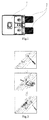
Fig.1 , the existing attachedTV signal tuner 1 is shaped like a box includingTV signal terminals 2. An attached TV signal tuner slot is reserved on the housing of a TV, and a baffle is arranged at the entry to the slot. As illustrated inFig.2 , the user installs the existing attachedTV signal tuner 1 by firstly detaching the baffle at the entry to the slot using a screwdriver, then inserting the existing attachedTV signal tuner 1 into the slot in the direction denoted by the arrow, and pushing the existing attachedTV signal tuner 1 to the bottom of the slot, and next attaching back the baffle and fixing it using the screwdriver. - A drawback of the prior art lies in complicated installation of the existing attached TV signal tuner; and moreover such a significant space is occupied by the slot reserved for the existing attached TV signal tuner that there may be short of a layout space because there are an increasing number of attached devices supported by the smart TV.
- Embodiments of the present invention provide an attached TV signal tuner and an electronic device so as to install the attached TV signal tuner simply and conveniently and to save a space reserved for installing an attached device of a smart TV.
- An embodiment of the present invention provides an attached TV signal tuner including a TV signal tuner body and a USB terminal connected therewith, the USB terminal being capable of being engaged with a USB interface of a smart TV, and the TV signal tuner body including a first radio-frequency signal terminal, a second radio-frequency signal terminal, a tuner chip, and a signal switch, wherein:
- the tuner chip is connected with the USB terminal; and
- the signal switch connects the first radio-frequency signal terminal with the tuner chip at a first operating position, and the second radio-frequency signal terminal with the tuner chip at a second operating position.
- Preferably the TV signal tuner body and the USB terminal are connected through a USB wire rod.
- Preferably the USB terminal is a USB3.0 terminal, the USB interface is a USB3.0 interface, and the USB wire rod is a USB3.0 wire rod.
- Preferably the first radio-frequency signal terminal is a wired TV signal terminal, and the second radio-frequency signal terminal is a wireless TV signal terminal.
- As compared with the attached TV signal tuner in the prior art, with the USB terminal, the attached TV signal tuner according to the embodiment of the present invention will occupy a smaller space reserved for an external device of the smart TV, and can be installed simply.
- An embodiment of the present invention further provides an electronic device including the attached TV signal tuner according to any one of the technical solutions above.
- In order to make the technical solutions in the embodiments of the present invention or the prior art more apparent, the drawings to which reference is made in a description of the embodiments or the prior art will be briefly introduced below, and apparently the drawings to be described below are merely illustrative of some embodiments of the present invention, and those ordinarily skilled in the art can derive from these drawings other drawings without any inventive effort. In the drawings:
-
Fig.1 is a schematic structural diagram of the attached TV signal tuner in the prior art; -
Fig.2 is a schematic diagram of installing the attached TV signal tuner in the prior art; -
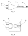
Fig.3 is a schematic structural diagram of an attached TV signal tuner according to an embodiment of the present invention; and -
Fig.4 is a schematic structural diagram of circuits in a TV signal tuner body according to an embodiment of the TV signal tuner. -
- 1-Existing attached TV signal tuner;
- 2-TV signal terminal;
- 3-TV signal tuner body;
- 4-USB terminal;
- 5-First radio-frequency signal terminal;
- 6-Second radio-frequency signal terminal;
- 7-USB wire rod;
- 8-Tuner chip;
- 9-Signal switch;
- 10-USB signal line.
- In order to make the objects, the technical solutions and the advantages of the present invention more apparent, the present invention will be further described in details with reference to the drawings. Apparently the described embodiments are only a part but all of the embodiments of the present invention. Based upon the embodiments of the present invention here, all of other embodiments derived by those ordinarily skilled in the art without any inventive effort shall come into the scope of the present invention.
- As illustrated in
Fig.3 and Fig.4 , an attached TV signal tuner according to an embodiment of the present invention includes a TVsignal tuner body 3 and aUSB terminal 4 connected therewith, theUSB terminal 4 can be engaged with a USB interface of a smart TV, and a circuitry structure of the TVsignal tuner body 3 includes a first radio-frequency signal terminal 5, a second radio-frequency signal terminal 6, atuner chip 8, and asignal switch 9, where thetuner chip 8 is connected with theUSB terminal 4 through aUSB signal line 10, and thesignal switch 9 connects the first radio-frequency signal terminal 5 with thetuner chip 8 at a first operating position, and the second radio-frequency signal terminal 6 with thetuner chip 8 at a second operating position. - The
tuner chip 8 can convert data information obtained from the first radio-frequency signal terminal 5 or the second radio-frequency signal terminal 6 into data information compliant with the Universal Serial Bus (USB) protocol, and exchange data with the TV set through aUSB wire rod 7 and theUSB terminal 4. The USB protocol is an external bus standard specifying connection and communication between a computer and an external device. The USB interface is convenient to use, supports a Plug and Play mode, and can be connected flexibly, power on its own, and be connected with a variety of external devices, so the USB interface is widely on personal computers and smart devices at present. With the USB interface, the computers or the smart devices can identify automatically the type of an attached device and further start a corresponding software configuration. - After the user going to access the attached TV signal tuner according to the embodiment of the present invention, engages the USB terminal of the attached TV signal tuner with the USB interface of the smart TV, the smart TV will identify automatically the attached TV signal tuner and start the corresponding software configuration, and the user can select a TV signal, and receive a TV program, by operating on the corresponding software. As compared with the attached TV signal tuner in the prior art, the attached TV signal tuner according to the embodiment of the present invention will occupy a smaller space reserved for an external device of the smart TV, and can be installed simply.
- As illustrated in
Fig.3 , in an embodiment of the present invention, the TVsignal tuner body 3 and theUSB terminal 4 are connected through theUSB wire rod 7. With the SUB wire rod, the distance between theUSB terminal 4 and the TVsignal tuner body 3 can be increased so that the TVsignal tuner body 3 can be placed flexibly in position. - In an embodiment of the present invention, the
USB terminal 4 in use is a USB3.0 terminal, the USB interface is a USB3.0 interface, and theUSB wire rod 7 is a USB3.0 wire rod. - The existing USB interfaces generally include USB2.0 and USB3.0 interfaces. Data of the USB3.0 interface are transmitted over 9 lines, which are more than 4 lines over which USB2.0 data are transmitted, and the USB3.0 interface and the USB3.0 wire rod can be compatible with the USB2.0. The broadest transmission bandwidth of the USB3.0 interface is up to 5.0Gbps (500MB/s), which is more than 8 times the transmission bandwidth of the USB2.0. There is a strict electrical specification in the USB3.0 standard to ensure the integrity of a high-speed signal as much as possible.
- The attached TV signal tuner according to the embodiment of the present invention supports an input of both a wireless TV signal and a wired TV signal thereto. Particularly the first radio-
frequency signal terminal 5 is a wired TV signal terminal, and the second radio-frequency signal terminal 6 is a wireless TV signal terminal. The user can select one of the TV signals on the TV interface, and the selection information can be transmitted to thetuner chip 8 via the USB interface, so that thetuner chip 8 can control thesignal switch 9 to be connected with the corresponding signal terminal selected by the user. - An embodiment of the present invention further provides an electronic device including the attached TV signal tuner according to any one of the technical solutions above. The electronic device can include a smart TV, a display device, etc., but will not be limited thereto.
- Last it shall be noted that the embodiments above are merely illustrative of the technical solutions according to the present invention but not intended to limit them; and although the present invention has been described in details with reference to the embodiments above, those ordinarily skilled in the art shall appreciate that they still can modify the technical solutions according to the respective embodiments above, or make equivalent substitutions to a part of the technical features therein; and the essence of the corresponding technical solutions will not depart from the spirit and scope of technical solutions according to the respective embodiments of the present invention due to these modifications or substitutions.
Claims (5)
- An attached TV signal tuner, comprising a TV signal tuner body and a USB terminal connected therewith, the USB terminal being capable of being engaged with a USB interface of a smart TV, and the TV signal tuner body comprising a first radio-frequency signal terminal, a second radio-frequency signal terminal, a tuner chip, and a signal switch, wherein:the tuner chip is connected with the USB terminal; andthe signal switch connects the first radio-frequency signal terminal with the tuner chip at a first operating position, and the second radio-frequency signal terminal with the tuner chip at a second operating position.
- The attached TV signal tuner according to claim 1, wherein the TV signal tuner body and the USB terminal are connected through a USB wire rod.
- The attached TV signal tuner according to claim 1 or 2, wherein the USB terminal is a USB3.0 terminal, the USB interface is a USB3.0 interface, and the USB wire rod is a USB3.0 wire rod.
- The attached TV signal tuner according to claim 3, wherein the first radio-frequency signal terminal is a wired TV signal terminal, and the second radio-frequency signal terminal is a wireless TV signal terminal.
- An electronic device, comprising the attached TV signal tuner according to any one of claims 1 to 4.
Applications Claiming Priority (1)
| Application Number | Priority Date | Filing Date | Title |
|---|---|---|---|
| CN201520416735.2U CN204707191U (en) | 2015-06-16 | 2015-06-16 | A kind of external TV signal tuner and electronic equipment |
Publications (1)
| Publication Number | Publication Date |
|---|---|
| EP3107303A1 true EP3107303A1 (en) | 2016-12-21 |
Family
ID=54286783
Family Applications (1)
| Application Number | Title | Priority Date | Filing Date |
|---|---|---|---|
| EP16172944.7A Withdrawn EP3107303A1 (en) | 2015-06-16 | 2016-06-03 | Attached tv signal tuner and electronic device |
Country Status (4)
| Country | Link |
|---|---|
| US (1) | US20160373683A1 (en) |
| EP (1) | EP3107303A1 (en) |
| CN (1) | CN204707191U (en) |
| TW (1) | TWM532121U (en) |
Citations (1)
| Publication number | Priority date | Publication date | Assignee | Title |
|---|---|---|---|---|
| CN2907120Y (en) * | 2006-04-08 | 2007-05-30 | 陕西凌华电子有限公司 | Novel active antenna splitter for digital TV |
-
2015
- 2015-06-16 CN CN201520416735.2U patent/CN204707191U/en not_active Expired - Fee Related
-
2016
- 2016-06-01 US US15/170,001 patent/US20160373683A1/en not_active Abandoned
- 2016-06-03 EP EP16172944.7A patent/EP3107303A1/en not_active Withdrawn
- 2016-06-08 TW TW105208646U patent/TWM532121U/en not_active IP Right Cessation
Patent Citations (1)
| Publication number | Priority date | Publication date | Assignee | Title |
|---|---|---|---|---|
| CN2907120Y (en) * | 2006-04-08 | 2007-05-30 | 陕西凌华电子有限公司 | Novel active antenna splitter for digital TV |
Non-Patent Citations (1)
| Title |
|---|
| ANONYMOUS: "HP USB Digital/Analog TV Tuner (User Guide)", 1 August 2008 (2008-08-01), XP055313219, Retrieved from the Internet <URL:http://www.hp.com/ctg/Manual/c02034843.pdf> [retrieved on 20161024] * |
Also Published As
| Publication number | Publication date |
|---|---|
| US20160373683A1 (en) | 2016-12-22 |
| CN204707191U (en) | 2015-10-14 |
| TWM532121U (en) | 2016-11-11 |
Similar Documents
| Publication | Publication Date | Title |
|---|---|---|
| US7921233B2 (en) | Signal converter for an all-in-one USB connector that includes USB 2.0, USB 3.0 and eSATA | |
| CN102572352B (en) | HDMI multiplexing method, HDMI, and equipped provided with HDMI | |
| US8066515B2 (en) | Multiple graphics adapter connection systems | |
| US9997850B2 (en) | Electronic device including connector | |
| CN102665302B (en) | A kind of wireless communication system | |
| US10339090B2 (en) | System for implementing MXM on a PCI card | |
| US20090043936A1 (en) | Docking station and expandable computer system | |
| US9043528B2 (en) | Bridge between a peripheral component interconnect express interface and a universal serial bus 3.0 device | |
| TW201344453A (en) | Operating M-PHY based communications over universal serial bus (USB) interface, and related cables, connectors, systems and methods | |
| US20080244141A1 (en) | High bandwidth cable extensions | |
| US7354275B2 (en) | Graphics card connector module, and motherboard device having the same | |
| US20120083212A1 (en) | Data transmitting system and data transmitting method | |
| EP2696291A1 (en) | Expansion module and cloud device thereof | |
| CN101551707A (en) | Switcher and method capable of transmitting image signal to universal serial bus display | |
| TWI598738B (en) | Interface expansion device | |
| US20150039797A1 (en) | Removable expansion interface device | |
| US20160373683A1 (en) | Attached tv signal tuner and electronic device | |
| US9373301B2 (en) | Image processing device, image processing chip and image processing method | |
| CN204856476U (en) | Interface arrangement and connecting device | |
| US20150029199A1 (en) | Electronic device with different processing modes | |
| US9465765B2 (en) | All-in-one SATA interface storage device | |
| CN205486071U (en) | Hand -held device | |
| CN102789440A (en) | Data transmission system | |
| US20050086561A1 (en) | Testing device | |
| US10050360B2 (en) | Interface card adapting device structure |
Legal Events
| Date | Code | Title | Description |
|---|---|---|---|
| PUAI | Public reference made under article 153(3) epc to a published international application that has entered the european phase |
Free format text: ORIGINAL CODE: 0009012 |
|
| 17P | Request for examination filed |
Effective date: 20160609 |
|
| AK | Designated contracting states |
Kind code of ref document: A1 Designated state(s): AL AT BE BG CH CY CZ DE DK EE ES FI FR GB GR HR HU IE IS IT LI LT LU LV MC MK MT NL NO PL PT RO RS SE SI SK SM TR |
|
| AX | Request for extension of the european patent |
Extension state: BA ME |
|
| RAP1 | Party data changed (applicant data changed or rights of an application transferred) |
Owner name: LE SHI ZHI XIN ELECTRONIC TECHNOLOGY (TIAN JIN) LI |
|
| 17Q | First examination report despatched |
Effective date: 20170217 |
|
| STAA | Information on the status of an ep patent application or granted ep patent |
Free format text: STATUS: THE APPLICATION IS DEEMED TO BE WITHDRAWN |
|
| 18D | Application deemed to be withdrawn |
Effective date: 20170628 |