EP3107136A1 - Rechargeable battery - Google Patents
Rechargeable battery Download PDFInfo
- Publication number
- EP3107136A1 EP3107136A1 EP16154752.6A EP16154752A EP3107136A1 EP 3107136 A1 EP3107136 A1 EP 3107136A1 EP 16154752 A EP16154752 A EP 16154752A EP 3107136 A1 EP3107136 A1 EP 3107136A1
- Authority
- EP
- European Patent Office
- Prior art keywords
- case
- hole
- electrode
- rechargeable battery
- terminal
- Prior art date
- Legal status (The legal status is an assumption and is not a legal conclusion. Google has not performed a legal analysis and makes no representation as to the accuracy of the status listed.)
- Granted
Links
Images




Classifications
-
- H—ELECTRICITY
- H01—ELECTRIC ELEMENTS
- H01M—PROCESSES OR MEANS, e.g. BATTERIES, FOR THE DIRECT CONVERSION OF CHEMICAL ENERGY INTO ELECTRICAL ENERGY
- H01M4/00—Electrodes
- H01M4/02—Electrodes composed of, or comprising, active material
- H01M4/13—Electrodes for accumulators with non-aqueous electrolyte, e.g. for lithium-accumulators; Processes of manufacture thereof
- H01M4/133—Electrodes based on carbonaceous material, e.g. graphite-intercalation compounds or CFx
-
- H—ELECTRICITY
- H01—ELECTRIC ELEMENTS
- H01M—PROCESSES OR MEANS, e.g. BATTERIES, FOR THE DIRECT CONVERSION OF CHEMICAL ENERGY INTO ELECTRICAL ENERGY
- H01M10/00—Secondary cells; Manufacture thereof
- H01M10/04—Construction or manufacture in general
- H01M10/0436—Small-sized flat cells or batteries for portable equipment
-
- H—ELECTRICITY
- H01—ELECTRIC ELEMENTS
- H01M—PROCESSES OR MEANS, e.g. BATTERIES, FOR THE DIRECT CONVERSION OF CHEMICAL ENERGY INTO ELECTRICAL ENERGY
- H01M10/00—Secondary cells; Manufacture thereof
- H01M10/04—Construction or manufacture in general
- H01M10/0431—Cells with wound or folded electrodes
-
- H—ELECTRICITY
- H01—ELECTRIC ELEMENTS
- H01M—PROCESSES OR MEANS, e.g. BATTERIES, FOR THE DIRECT CONVERSION OF CHEMICAL ENERGY INTO ELECTRICAL ENERGY
- H01M10/00—Secondary cells; Manufacture thereof
- H01M10/05—Accumulators with non-aqueous electrolyte
- H01M10/052—Li-accumulators
- H01M10/0525—Rocking-chair batteries, i.e. batteries with lithium insertion or intercalation in both electrodes; Lithium-ion batteries
-
- H—ELECTRICITY
- H01—ELECTRIC ELEMENTS
- H01M—PROCESSES OR MEANS, e.g. BATTERIES, FOR THE DIRECT CONVERSION OF CHEMICAL ENERGY INTO ELECTRICAL ENERGY
- H01M4/00—Electrodes
- H01M4/02—Electrodes composed of, or comprising, active material
- H01M4/13—Electrodes for accumulators with non-aqueous electrolyte, e.g. for lithium-accumulators; Processes of manufacture thereof
- H01M4/131—Electrodes based on mixed oxides or hydroxides, or on mixtures of oxides or hydroxides, e.g. LiCoOx
-
- H—ELECTRICITY
- H01—ELECTRIC ELEMENTS
- H01M—PROCESSES OR MEANS, e.g. BATTERIES, FOR THE DIRECT CONVERSION OF CHEMICAL ENERGY INTO ELECTRICAL ENERGY
- H01M4/00—Electrodes
- H01M4/02—Electrodes composed of, or comprising, active material
- H01M4/36—Selection of substances as active materials, active masses, active liquids
- H01M4/48—Selection of substances as active materials, active masses, active liquids of inorganic oxides or hydroxides
- H01M4/485—Selection of substances as active materials, active masses, active liquids of inorganic oxides or hydroxides of mixed oxides or hydroxides for inserting or intercalating light metals, e.g. LiTi2O4 or LiTi2OxFy
-
- H—ELECTRICITY
- H01—ELECTRIC ELEMENTS
- H01M—PROCESSES OR MEANS, e.g. BATTERIES, FOR THE DIRECT CONVERSION OF CHEMICAL ENERGY INTO ELECTRICAL ENERGY
- H01M4/00—Electrodes
- H01M4/02—Electrodes composed of, or comprising, active material
- H01M4/36—Selection of substances as active materials, active masses, active liquids
- H01M4/58—Selection of substances as active materials, active masses, active liquids of inorganic compounds other than oxides or hydroxides, e.g. sulfides, selenides, tellurides, halogenides or LiCoFy; of polyanionic structures, e.g. phosphates, silicates or borates
- H01M4/583—Carbonaceous material, e.g. graphite-intercalation compounds or CFx
- H01M4/587—Carbonaceous material, e.g. graphite-intercalation compounds or CFx for inserting or intercalating light metals
-
- H—ELECTRICITY
- H01—ELECTRIC ELEMENTS
- H01M—PROCESSES OR MEANS, e.g. BATTERIES, FOR THE DIRECT CONVERSION OF CHEMICAL ENERGY INTO ELECTRICAL ENERGY
- H01M4/00—Electrodes
- H01M4/02—Electrodes composed of, or comprising, active material
- H01M4/64—Carriers or collectors
- H01M4/66—Selection of materials
- H01M4/661—Metal or alloys, e.g. alloy coatings
-
- H—ELECTRICITY
- H01—ELECTRIC ELEMENTS
- H01M—PROCESSES OR MEANS, e.g. BATTERIES, FOR THE DIRECT CONVERSION OF CHEMICAL ENERGY INTO ELECTRICAL ENERGY
- H01M50/00—Constructional details or processes of manufacture of the non-active parts of electrochemical cells other than fuel cells, e.g. hybrid cells
- H01M50/10—Primary casings; Jackets or wrappings
- H01M50/102—Primary casings; Jackets or wrappings characterised by their shape or physical structure
- H01M50/103—Primary casings; Jackets or wrappings characterised by their shape or physical structure prismatic or rectangular
-
- H—ELECTRICITY
- H01—ELECTRIC ELEMENTS
- H01M—PROCESSES OR MEANS, e.g. BATTERIES, FOR THE DIRECT CONVERSION OF CHEMICAL ENERGY INTO ELECTRICAL ENERGY
- H01M50/00—Constructional details or processes of manufacture of the non-active parts of electrochemical cells other than fuel cells, e.g. hybrid cells
- H01M50/10—Primary casings; Jackets or wrappings
- H01M50/172—Arrangements of electric connectors penetrating the casing
- H01M50/174—Arrangements of electric connectors penetrating the casing adapted for the shape of the cells
- H01M50/176—Arrangements of electric connectors penetrating the casing adapted for the shape of the cells for prismatic or rectangular cells
-
- H—ELECTRICITY
- H01—ELECTRIC ELEMENTS
- H01M—PROCESSES OR MEANS, e.g. BATTERIES, FOR THE DIRECT CONVERSION OF CHEMICAL ENERGY INTO ELECTRICAL ENERGY
- H01M50/00—Constructional details or processes of manufacture of the non-active parts of electrochemical cells other than fuel cells, e.g. hybrid cells
- H01M50/50—Current conducting connections for cells or batteries
- H01M50/543—Terminals
- H01M50/552—Terminals characterised by their shape
- H01M50/553—Terminals adapted for prismatic, pouch or rectangular cells
-
- H—ELECTRICITY
- H01—ELECTRIC ELEMENTS
- H01M—PROCESSES OR MEANS, e.g. BATTERIES, FOR THE DIRECT CONVERSION OF CHEMICAL ENERGY INTO ELECTRICAL ENERGY
- H01M4/00—Electrodes
- H01M4/02—Electrodes composed of, or comprising, active material
- H01M2004/026—Electrodes composed of, or comprising, active material characterised by the polarity
- H01M2004/027—Negative electrodes
-
- H—ELECTRICITY
- H01—ELECTRIC ELEMENTS
- H01M—PROCESSES OR MEANS, e.g. BATTERIES, FOR THE DIRECT CONVERSION OF CHEMICAL ENERGY INTO ELECTRICAL ENERGY
- H01M4/00—Electrodes
- H01M4/02—Electrodes composed of, or comprising, active material
- H01M2004/026—Electrodes composed of, or comprising, active material characterised by the polarity
- H01M2004/028—Positive electrodes
-
- H—ELECTRICITY
- H01—ELECTRIC ELEMENTS
- H01M—PROCESSES OR MEANS, e.g. BATTERIES, FOR THE DIRECT CONVERSION OF CHEMICAL ENERGY INTO ELECTRICAL ENERGY
- H01M2220/00—Batteries for particular applications
- H01M2220/20—Batteries in motive systems, e.g. vehicle, ship, plane
-
- H—ELECTRICITY
- H01—ELECTRIC ELEMENTS
- H01M—PROCESSES OR MEANS, e.g. BATTERIES, FOR THE DIRECT CONVERSION OF CHEMICAL ENERGY INTO ELECTRICAL ENERGY
- H01M50/00—Constructional details or processes of manufacture of the non-active parts of electrochemical cells other than fuel cells, e.g. hybrid cells
- H01M50/10—Primary casings; Jackets or wrappings
- H01M50/147—Lids or covers
- H01M50/148—Lids or covers characterised by their shape
- H01M50/15—Lids or covers characterised by their shape for prismatic or rectangular cells
-
- H—ELECTRICITY
- H01—ELECTRIC ELEMENTS
- H01M—PROCESSES OR MEANS, e.g. BATTERIES, FOR THE DIRECT CONVERSION OF CHEMICAL ENERGY INTO ELECTRICAL ENERGY
- H01M50/00—Constructional details or processes of manufacture of the non-active parts of electrochemical cells other than fuel cells, e.g. hybrid cells
- H01M50/40—Separators; Membranes; Diaphragms; Spacing elements inside cells
- H01M50/409—Separators, membranes or diaphragms characterised by the material
- H01M50/411—Organic material
- H01M50/414—Synthetic resins, e.g. thermoplastics or thermosetting resins
- H01M50/417—Polyolefins
-
- H—ELECTRICITY
- H01—ELECTRIC ELEMENTS
- H01M—PROCESSES OR MEANS, e.g. BATTERIES, FOR THE DIRECT CONVERSION OF CHEMICAL ENERGY INTO ELECTRICAL ENERGY
- H01M50/00—Constructional details or processes of manufacture of the non-active parts of electrochemical cells other than fuel cells, e.g. hybrid cells
- H01M50/50—Current conducting connections for cells or batteries
- H01M50/531—Electrode connections inside a battery casing
- H01M50/534—Electrode connections inside a battery casing characterised by the material of the leads or tabs
-
- H—ELECTRICITY
- H01—ELECTRIC ELEMENTS
- H01M—PROCESSES OR MEANS, e.g. BATTERIES, FOR THE DIRECT CONVERSION OF CHEMICAL ENERGY INTO ELECTRICAL ENERGY
- H01M50/00—Constructional details or processes of manufacture of the non-active parts of electrochemical cells other than fuel cells, e.g. hybrid cells
- H01M50/50—Current conducting connections for cells or batteries
- H01M50/531—Electrode connections inside a battery casing
- H01M50/538—Connection of several leads or tabs of wound or folded electrode stacks
-
- Y—GENERAL TAGGING OF NEW TECHNOLOGICAL DEVELOPMENTS; GENERAL TAGGING OF CROSS-SECTIONAL TECHNOLOGIES SPANNING OVER SEVERAL SECTIONS OF THE IPC; TECHNICAL SUBJECTS COVERED BY FORMER USPC CROSS-REFERENCE ART COLLECTIONS [XRACs] AND DIGESTS
- Y02—TECHNOLOGIES OR APPLICATIONS FOR MITIGATION OR ADAPTATION AGAINST CLIMATE CHANGE
- Y02E—REDUCTION OF GREENHOUSE GAS [GHG] EMISSIONS, RELATED TO ENERGY GENERATION, TRANSMISSION OR DISTRIBUTION
- Y02E60/00—Enabling technologies; Technologies with a potential or indirect contribution to GHG emissions mitigation
- Y02E60/10—Energy storage using batteries
-
- Y—GENERAL TAGGING OF NEW TECHNOLOGICAL DEVELOPMENTS; GENERAL TAGGING OF CROSS-SECTIONAL TECHNOLOGIES SPANNING OVER SEVERAL SECTIONS OF THE IPC; TECHNICAL SUBJECTS COVERED BY FORMER USPC CROSS-REFERENCE ART COLLECTIONS [XRACs] AND DIGESTS
- Y02—TECHNOLOGIES OR APPLICATIONS FOR MITIGATION OR ADAPTATION AGAINST CLIMATE CHANGE
- Y02P—CLIMATE CHANGE MITIGATION TECHNOLOGIES IN THE PRODUCTION OR PROCESSING OF GOODS
- Y02P70/00—Climate change mitigation technologies in the production process for final industrial or consumer products
- Y02P70/50—Manufacturing or production processes characterised by the final manufactured product
Definitions
- the present disclosure relates to a rechargeable battery.
- a rechargeable battery differs from a primary battery in that it can be repeatedly charged and discharged, while the latter is incapable of being recharged. Research has been actively conducted for applying the rechargeable battery to high technology fields, and as a result, the rechargeable battery is commercially available and widely used.
- Such a rechargeable battery which may be referred to as a battery cell, is manufactured in various shapes such as a cylindrical, prismatic, or pouch shape, and a medium to large battery module that requires high power is configured to include a cylindrical or prismatic rechargeable battery that can easily implement high capacity.
- an electrode assembly that is formed by interposing a separator acting as an insulator between positive and negative electrodes and an electrolyte solution are accommodated in a case at which a cap plate is installed.
- a positive electrode terminal and a negative terminal are connected to the electrode assembly, and they are formed to be protruded outside through the cap plate.
- the height of the cell is increased, which may cause the height of electric vehicles housing the cells to increase.
- the present disclosure has been made in an effort to provide a rechargeable battery that may be arranged in a compact structure to occupy a small volume when a battery module is configured, may improve flexibility of a position at which a circuit for the battery module is formed, and may reduce a height of the battery module.
- An exemplary embodiment of the present disclosure provides a rechargeable battery including: an electrode assembly that includes a first electrode, a second electrode, and a separator interposed between the first electrode and the second electrode; a case that accommodates the electrode assembly, in one lateral surface of which a hole is formed, and that includes an opening formed in another lateral surface facing the one lateral surface; a sealing portion that forms a first terminal that is connected to the hole and seals the hole so that a lateral surface of the case is flattened; a cap plate combined with the opening; and a second terminal that is connected to the second electrode and is protruded outside the case while passing through the cap plate, wherein the hole may include a shape recessed toward the electrode assembly with respect to a surface of the case.
- the recessed shape may form a step with respect to the surface of the case.
- a size of the hole formed in the one lateral surface of the case may be larger than that of a hole of the shape recessed toward the electrode assembly.
- the size may be a vertical width of the hole.
- the sealing portion may be positioned in the larger hole in the lateral surface of the case.
- the sealing portion may be positioned in both the larger hole and the recessed hole in the lateral surface of the case.
- the sealing portion may include a tilted outer surface to contact the tilted lateral wall.
- the recessed shape may include a lateral wall perpendicular to the surface of the case.
- the recessed shape may include a lateral wall tilted to the surface of the case.
- the sealing portion may be formed of the same material as the case and may be directly bonded to an uncoated region formed in the first electrode.
- the sealing portion may form a first terminal connected to the first electrode.
- the first terminal may be formed to pass through the hole and may be combined with the hole to not be protruded from the surface of the case.
- An insulating member may be disposed between the second terminal and the cap plate, and an uncoated region formed in the second electrode may be directly combined with the second terminal.
- a rechargeable battery may include a hole (or an opening) formed in one lateral surface of a case and having a shape recessed in a direction of an electrode assembly, such that a positive electrode terminal and a negative electrode terminal may be respectively formed on opposite surfaces of the case or only a single terminal may be included therein.
- a circuit for the battery module may be designed and formed on a lateral area of the battery module in addition to an upper area of the battery module depending on the designer's convenience, and an overall height of the battery module may decrease and the rechargeable batteries may be arranged in a compact structure, thereby increasing the capacity of the battery module in the same volume.
- FIG. 1 illustrates a perspective view of a rechargeable battery according to a first exemplary embodiment of the present disclosure
- FIG. 2 illustrates an exploded perspective view of the rechargeable battery according to the first exemplary embodiment of the present disclosure
- FIG. 3 illustrates a longitudinal cross-sectional view taken along line III-III of FIG. 1 .
- a rechargeable battery 101 includes an electrode assembly 10, a case 20, a sealing portion 35, a cap plate 50, and a second terminal 31.
- the sealing portion 35 is not shown in FIGS. 1 and 2 .
- a prismatic lithium ion rechargeable battery will be described as an example, but the present disclosure is not limited thereto, and may be applicable to various types of batteries such as a pouch battery, a lithium polymer battery, and the like.
- the electrode assembly 10 included in the rechargeable battery 101 includes a band-shaped positive electrode (first electrode) 11, a band-shaped negative electrode (second electrode) 12, and a separator 13 disposed between the positive electrode 11 and the negative electrode 12, and it is formed as a spirally wound structure. That is, the electrode assembly 10 is flatly pressed after being spirally wound based on a winding axis while interposing the separator 13 between the positive electrode 11 and the negative electrode 12.
- the positive electrode 11 includes a positive electrode current collector and a positive electrode active material layer coated on the positive electrode current collector, and the positive electrode current collector may be formed of a metal thin plate that is made of a material such as aluminum, while the positive electrode active material layer may be made of a lithium-based oxide.
- the negative electrode 12 includes a negative electrode current collector and a negative active material layer coated on the negative electrode current collector, and the negative electrode current collector may be formed of a metal thin plate that is made of a material such as copper, while the negative active material layer may be made of a carbon-based active material.
- the separator 13 may be formed of a porous thin film such as a polyolefin-based resin.
- a positive electrode uncoated region 11a protruded toward a lateral surface 23 of the case may be formed on one lateral end of the electrode assembly 10, and a negative uncoated region 12a protruded toward an opening 25 of the case may be formed on another lateral end of the electrode assembly 10.
- a number of the positive electrode uncoated regions 11a and the negative uncoated regions 12a may be respectively protruded and welded at one current collector (not shown) to be connected to the case, or a plurality of positive electrode uncoated regions 11a and negative uncoated regions 12a may be respectively protruded long in a band shape to be directly connected to the case, but the present disclosure is not limited thereto.
- the case 20 is formed in a horizontal quadrangular pillar shape, a hole is formed in one lateral surface 23 of the case 20, and the opening 25 is formed on the other lateral surface facing the one lateral surface 23.
- the electrode assembly 10 is inserted into the case 20 through the opening 25.
- the case 20 includes an external circumferential surface 21 and the lateral surface 23 that is formed on one side of the case 20 and is connected to the external circumferential surface 21.
- the hole 26 is formed in a center portion of the lateral surface 23, and the hole 26 has a shape recessed to the electrode assembly 10 with respect to the lateral surface 23.
- the electrode assembly 10 is disposed between the positive electrode uncoated region 11a and the negative uncoated region 12a, and the positive electrode uncoated region 11a is disposed at one side of the electrode assembly 10 and the negative uncoated region 12a is disposed at the other side of the electrode assembly 10.
- the electrode assembly 10 may be inserted into the case 20 through the opening 25 while the positive electrode 11 is directed toward the hole 26.
- the hole 26 may include a shape recessed to the electrode assembly 10, and the recessed shape may form a step with respect to a surface of the case 20.
- the step may be formed so that a hole 26b formed in the lateral surface 23 of the case 20 is formed to be larger than a hole 26c with a shape recessed toward the electrode assembly 10 and thus a lateral wall 26a bent in a stepped shape is formed. Accordingly, when the hole 26 is formed to include the step and the sealing portion 35 is combined with the case 20, since the case 20 may be easily sealed by welding, process efficiency may be improved.
- the hole 26 of the lateral surface 23 of the case 20, which is formed to include the step, is enlarged and showed in FIG. 3 .
- the sealing portion 35 and a bonding portion 11ab of the positive electrode uncoated region bonded to the sealing portion 35 are not shown for convenience in the enlarged portion of FIG 3 .
- the hole 26 formed in the lateral surface 23 of the case is formed in a shape recessed toward the electrode assembly 10.
- the hole 26 includes the outer hole 26b formed in the lateral surface 23 of the case and the inner hole 26c formed to be recessed toward the electrode assembly 10.
- the hole 26 is formed to have the lateral wall 26a with a stepped shape perpendicular to the case lateral surface 23.
- the hole 26 is formed to include a transverse cross-section of a polygonal shape in which two rectangles with different vertical widths are combined, and a distance between the lateral walls 26cc of the inner hole 26c formed to be recessed toward the electrode assembly 10 is shorter than that between the lateral walls 26bb of the outer hole 26b formed in the lateral surface 23 of the case. Accordingly, if the sealing portion 35 is manufactured to fit only the outer hole 26b of the lateral surface 23 of the case 20, the sealing portion 35 may be more easily manufactured.
- the sealing portion 35 should be sealed so that the lateral surface 23 of the case 20 is flattened, that is, so that the lateral surface 23 of the case 20 is not protruded. Accordingly, it may be preferable that a thickness of the sealing portion 35 is substantially equal to a height of the lateral wall 26bb of the hole 26b formed in the lateral surface 23 of the case 20 among the lateral walls 26a of the stepped shape.
- the sealing portion 35 may be formed in the same shape as the hole 26b to seal the outer hole 26b formed in the lateral surface 23 of the case 20, and it may be made of the same material as the case 20.
- the bonding portion 11ab of the positive electrode uncoated region is bent to substantially have the same thickness as the hole 26c recessed from the lateral surface 23 of the case 20 toward the electrode assembly, specifically, to be sealed parallel to the sealing portion 35, and it is accommodated inside the inner hole 26c. Accordingly, a tilt connection portion 11aa formed to be tilted with respect to the external circumferential surface of the electrode assembly 10 and the bonding portion 11ab that is bent from the tilt connection portion 11aa and is welded to the sealing portion 35 are formed in the positive electrode uncoated region 11a.
- the bonding portion 11ab of the positive electrode uncoated region 11a is directly welded to the sealing portion 35, and the sealing portion 35 is welded to the hole 26, such that the case 20 and the sealing portion 35 are charged as a positive electrode 11. Accordingly, since the case 20 can function as the positive electrode 11 without a separate positive electrode terminal, a space for forming a positive electrode terminal is not required in the battery module.
- the positive electrode 11 is connected to the sealing portion 35, and the second terminal 31 is welded to be bonded to the negative electrode 12.
- the second terminal 31 is bonded to the negative uncoated region 12a by welding, and is protruded to the outside while passing through a terminal hole 51 of the cap plate 50.
- the second terminal 31 is welded to an outer surface of the negative uncoated region 12a, and the negative uncoated region 12 is bent to be disposed parallel to the second terminal 31 and the cap plate 50. Accordingly, a tilt connection portion 12aa formed to be tilted with respect to the external circumferential surface of the electrode assembly 10 and a bonding portion 12ab that is bent from the tilt connection portion 12aa and is welded to the second terminal 31 are formed in the negative uncoated region 12a.
- the second terminal 31 is fixed to the cap plate 50 with an insulating member 32 therebetween, and the insulating member 32 is disposed between the cap plate 50 and the second terminal 31 to electrically insulate the second terminal 31 from the cap plate 50.
- the negative uncoated region 12a is directly welded to one surface of the second terminal 31.
- the second terminal 31 may be formed in a rivet form in which ends of the second terminal 31 are widely spread by being pressed in a state for the second terminal 31 to pass through the terminal hole 51 formed in the cap plate 50.
- the sealing portion 35 made of the same material as the case 20 is directly connected to the positive electrode 11 of the electrode assembly 10, a structure of the rechargeable battery may be simplified and thus a manufacturing cost thereof may be reduced, and a manufacturing process thereof may be simplified and thus productivity thereof may be improved.
- the rechargeable batteries 101 of the present disclosure may be arranged in a compact structure. Further, when a cooling process is performed due to deterioration of respective rechargeable batteries 101, cooling efficiency may be easily improved by only circulating air and/or fluid without applying a separate coolant, thereby decreasing the cost of the cooling process.
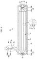
- FIG. 4 illustrates a longitudinal cross-sectional view of a rechargeable battery according to a second exemplary embodiment of the present disclosure.
- a rechargeable battery 101 according to the second exemplary embodiment includes the same structure as the rechargeable battery according to the first exemplary embodiment, except for a shape of a sealing portion 35 and a shape of a hole 26 formed in the lateral surface 23 of the case 20, a duplicate description of the same structure will be omitted.
- the rechargeable battery 101 includes the electrode assembly 10, the case 20, the cap plate 50, the sealing portion 35, and the second terminal 31.
- the sealing portion 35 is connected to the positive electrode 11, and the second terminal 31 is bonded to the negative electrode 12 by welding.
- the positive electrode uncoated region 11a is bonded to the sealing portion 35 by welding, and the sealing portion 35 is connected to the hole 26 to not be protruded from the lateral surface 23 of the case 20 and seals the hole 26.
- the second terminal 31 is bonded to the negative uncoated region 12a by welding and is protruded outside while passing through the cap plate 50.
- the opening 25 of the case 20 is formed in an opposite lateral surface facing the lateral surface 23 where the hole 26 is formed in order to accommodate the electrode assembly 10, and the case 20 is formed to have a horizontal quadrangular pillar shape.
- the case 20 includes the external circumferential surface 21 and the lateral surface 23 that is formed in one side of the case 20, and is connected to the external circumferential surface 21.
- the hole 26 is formed in a center portion of the lateral surface 23, the sealing portion 35 is connected to the hole 26, and the sealing portion 35 is connected to the positive electrode 11 of electrode assembly 10 to be able to perform the function of the positive electrode 11 without a separate positive electrode terminal.
- the hole 26 is formed to have a shape recessed toward the electrode assembly 10.
- the hole 26 includes an outer hole 26b formed in the lateral surface 23 of the case and the inner hole 26c recessed toward the electrode assembly.
- the lateral wall 26bb of the outer hole 26b is formed to have a tilted surface
- the lateral wall 26cc of the inner hole 26c is formed to have the lateral wall 26cc perpendicular to the lateral surface 23 of the case.
- the hole 26 is formed to include a transverse cross-section of a polygonal shape in which a square shape and a rectangle shape that have a tilted upper portion and a tilted lower portion are combined, the lateral wall 26bb of the outer hole 26b formed in the lateral surface 23 of the case is tilted for the vertical width thereof to narrow closer to the electrode assembly 10, and the lateral wall 26cc of the inner hole 26c recessed toward the electrode assembly 10 is formed to be perpendicular to the lateral surface 23 of the case 20.
- the rechargeable battery according to the second exemplary embodiment of the present disclosure may have an advantage of more easily inserting the sealing portion 35 into the hole 26 of the lateral surface 23 of the battery case in addition to the above-mentioned advantages.
- FIG. 5 illustrates a longitudinal cross-sectional view of a rechargeable battery according to a third exemplary embodiment of the present disclosure.
- the rechargeable battery 101 according to the third exemplary embodiment includes the same structure as the rechargeable battery according to the first exemplary embodiment, except for a sealing portion 35 forming a first terminal 34 connected to the positive electrode 11 of the electrode assembly 10 and a bonding position at which the first terminal 34 and the positive electrode 11 of the electrode assembly 10 are bonded, a duplicate description of the same structure will be omitted.
- the rechargeable battery 101 includes the electrode assembly 10, the case 20, the cap plate 50, the first terminal 34, and the second terminal 31.
- the electrode assembly 10 includes the positive electrode 11, the negative electrode 12, and the separator 13 disposed between the positive electrode 11 and the negative electrode 12, and the positive electrode coated region where an active material is coated and the positive electrode uncoated region 11a where the active material is not coated are formed in the positive electrode 11.
- a negative electrode coated region where the active material is coated and the negative uncoated region 12a where the active material is not coated are formed in the negative electrode 12.
- the second terminal 31 is bonded to the negative uncoated region 12a by welding, and is protruded outside while passing through the cap plate 50. Since a structure of the second terminal 31 is the same as that of the first exemplary embodiment, a description thereof will be omitted.
- the opening 25 of the case 20 is formed in an opposite lateral surface facing the lateral surface 23 where the hole 26 is formed in order to accommodate the electrode assembly 10, and the case 20 is formed to have a horizontal quadrangular pillar shape.
- the case 20 includes the external circumferential surface 21 and the lateral surface 23 connected to the external circumferential surface 21.
- the hole 26 with a step is formed in the lateral surface 23, and the first terminal 34 is inserted into the hole 26.
- the hole 26 includes the outer hole 26b formed in the lateral surface 23 of the case and the inner hole 26c recessed toward the electrode assembly.
- the hole 26 is formed to have the lateral wall 26a with a stepped shape perpendicular to the case lateral surface 23.
- the hole 26 is formed to include a transverse cross-section of a polygonal shape in which two rectangles with different vertical widths are combined, and a distance between the lateral walls 26cc of the inner hole 26c formed to be recessed toward the electrode assembly 10 is shorter than that between the lateral walls 26bb of the outer hole 26b formed in the lateral surface 23 of the case.
- the first terminal 34 is formed in substantially the same shape as the above-described hole 26, and contacts both the surface 26bb and the surface 26cc, and is directly bonded to the bonding portion 11ab of the positive electrode 11 by welding.
- the welding can be performed by ultrasonic welding.
- the first terminal 34 passes through and is inserted into the hole 26 with the step, and the first terminal 34 is bonded to the lateral surface 23 to not be protruded from the lateral surface 23 of the case 20 so that the lateral surface 23 of the case 20 has a flattened shape.
- the rechargeable battery according to the third exemplary embodiment of the present disclosure has advantages that the manufacturing process thereof is simplified and a contact area between the first terminal 34 and the case is enlarged because the first terminal 34 acts as the sealing portion, in addition to the above-mentioned advantages.
- FIG. 6 illustrates a longitudinal cross-sectional view of a rechargeable battery according to a fourth exemplary embodiment of the present disclosure.
- a rechargeable battery 101 according to the present exemplary embodiment has the same structure as the rechargeable battery according to the first exemplary embodiment, except for a sealing portion 35 forming a first terminal 34 connected to the positive electrode 11 of the electrode assembly 10 and a bonding position at which the first terminal 34 and the positive electrode 11 of the electrode assembly 10 are bonded, a duplicate description of the same structure will be omitted.
- the rechargeable battery 101 includes the electrode assembly 10, the case 20, the cap plate 50, the first terminal 34, and the second terminal 31.
- the electrode assembly 10 includes the positive electrode 11, the negative electrode 12, and the separator 13, and the positive electrode coated region where an active material is coated and the positive electrode uncoated region 11a where the active material is not coated are formed in the positive electrode 11.
- a negative electrode coated region where the active material is coated and the negative uncoated region 12a where the active material is not coated are formed in the negative electrode 12.
- the second terminal 31 is bonded to the negative uncoated region 12a by welding, and is protruded outside while passing through the cap plate 50.
- the insulating member 32 is disposed between the cap plate 50 and the second terminal 31.
- An insulating plate 37 is disposed below the cap plate 50 and is formed of a long rectangular plate, and one side of the second terminal 31 is inserted into the insulating plate 37. As such, when the insulating plate 37 is disposed, it is possible to prevent the negative uncoated region 12a from directly contacting the cap plate 50.
- the insulating plate 37 could be applied also to the first to third exemplary embodiments above.
- the opening 25 of the case 20 is formed in an opposite lateral surface facing the lateral surface 23 where the hole 26 is formed in order to accommodate the electrode assembly 10, and the case 20 is formed to have a horizontal quadrangular pillar shape.
- the case 20 includes the external circumferential surface 21 and the lateral surface 23 connected to the external circumferential surface 21.
- the hole 26 with a step is formed in the lateral surface 23, and the first terminal 34 is inserted into the hole 26.
- the hole 26 includes the outer hole 26b formed in the lateral surface 23 of the case and the inner hole 26c recessed toward the electrode assembly.
- the lateral wall 26bb of the outer hole 26b is formed to have a tilted surface
- the lateral wall 26cc of the inner hole 26c is formed to be perpendicular to the lateral surface 23 of the case.
- the hole 26 is formed to include a transverse cross-section of a polygonal shape in which a square shape and a rectangle shape that have a tilted upper portion and a tilted lower portion are combined, the lateral wall 26bb of the outer hole 26b formed in the lateral surface 23 of the case is tilted for the vertical width thereof to narrow closer to the electrode assembly 10, and the lateral wall 26cc of the inner hole 26c recessed toward the electrode assembly 10 is formed to be perpendicular to the lateral surface 23 of the case 20.
- the first terminal 34 is formed in substantially the same shape as the above-described hole 26, and contacts both the surface 26bb and the surface 26cc, and may be directly bonded to the positive electrode uncoated region 11a by welding. Specifically, in the fourth exemplary embodiment, the first terminal 34 is welded to the bonding portion 11ab of the positive electrode uncoated region 11a, and the welding may be performed by ultrasonic welding. The first terminal 34 passes through and is inserted into the hole 26 with the step, and the first terminal 34 is bonded to the lateral surface 23 to not be protruded from the lateral surface 23 of the case 20 so that the lateral surface 23 of the case 20 has a flattened shape.
- the rechargeable battery according to the fourth exemplary embodiment of the present disclosure has advantages that the first terminal 34 is easily inserted through a method inserting and putting the first terminal 34 into the hole 26, and that the manufacturing process thereof may be simplified and a contact area between the first terminal 34 and the case may be enlarged because the inserted and bonded first terminal 34 acts as a sealing portion, in addition to the above-mentioned advantages.
- the rechargeable battery that includes the structure in which only a single terminal is protruded from one side of the case by forming the hole with the step in the lateral surface of the case and by sealing the hole with the sealing portion or the first terminal directly and electrically connected to the positive electrode of the electrode assembly for the case lateral surface to be flattened in shape, may be manufactured.
- the circuit for the battery module may be designed and formed even on a lateral area of the battery module depending on the designer's convenience, and an overall height of the battery module may decrease, while the rechargeable batteries may be arranged in a compact structure.
- cooling efficiency may be easily improved only by circulating air and/or fluid in the lateral surface of the case without applying a separate coolant.
Landscapes
- Chemical & Material Sciences (AREA)
- Chemical Kinetics & Catalysis (AREA)
- Electrochemistry (AREA)
- General Chemical & Material Sciences (AREA)
- Engineering & Computer Science (AREA)
- Manufacturing & Machinery (AREA)
- Materials Engineering (AREA)
- Inorganic Chemistry (AREA)
- Connection Of Batteries Or Terminals (AREA)
- Sealing Battery Cases Or Jackets (AREA)
Abstract
Description
- The present disclosure relates to a rechargeable battery.
- A rechargeable battery differs from a primary battery in that it can be repeatedly charged and discharged, while the latter is incapable of being recharged. Research has been actively conducted for applying the rechargeable battery to high technology fields, and as a result, the rechargeable battery is commercially available and widely used.
- Recently, large capacity/high power rechargeable batteries using a non-aqueous electrolyte and having a high energy density have been developed, and the rechargeable batteries are connected in series and/or parallel, thereby forming a large capacity/ high power battery module in order to be able to be used in power storage applications and in devices that requires high powers.
- Such a rechargeable battery, which may be referred to as a battery cell, is manufactured in various shapes such as a cylindrical, prismatic, or pouch shape, and a medium to large battery module that requires high power is configured to include a cylindrical or prismatic rechargeable battery that can easily implement high capacity.
- In order to form the battery cell, an electrode assembly that is formed by interposing a separator acting as an insulator between positive and negative electrodes and an electrolyte solution are accommodated in a case at which a cap plate is installed. In this case, a positive electrode terminal and a negative terminal are connected to the electrode assembly, and they are formed to be protruded outside through the cap plate.
- When a battery module is formed by electrically connecting the battery cells, since the electrode terminals of the conventional art are fixed in a single direction, an additional space for connecting the electrode terminals is required, and thus the volume of the battery module increases. Further, since a circuit and the like for the battery module should be disposed on an upper portion of where the electrode terminals are disposed, flexibility for forming of the battery module decreases and user's selectivity is limited.
- Moreover, in some applications, such as electric vehicles, when the electrode terminals on the battery cell protrude from the upper portion of the battery cell, the height of the cell is increased, which may cause the height of electric vehicles housing the cells to increase.
- The above information disclosed in this Background section is only to enhance the understanding of the background of the disclosure and therefore it may contain information that does not form the prior art that is already known in this country to a person of ordinary skill in the art.
- The present disclosure has been made in an effort to provide a rechargeable battery that may be arranged in a compact structure to occupy a small volume when a battery module is configured, may improve flexibility of a position at which a circuit for the battery module is formed, and may reduce a height of the battery module.
- Technical objects desired to be achieved in the present disclosure are not limited to the aforementioned objects, and other technical objects not described above will be apparent to those skilled in the art from the disclosure of the present disclosure.
- An exemplary embodiment of the present disclosure provides a rechargeable battery including: an electrode assembly that includes a first electrode, a second electrode, and a separator interposed between the first electrode and the second electrode; a case that accommodates the electrode assembly, in one lateral surface of which a hole is formed, and that includes an opening formed in another lateral surface facing the one lateral surface; a sealing portion that forms a first terminal that is connected to the hole and seals the hole so that a lateral surface of the case is flattened; a cap plate combined with the opening; and a second terminal that is connected to the second electrode and is protruded outside the case while passing through the cap plate, wherein the hole may include a shape recessed toward the electrode assembly with respect to a surface of the case.
- The recessed shape may form a step with respect to the surface of the case. In the step, a size of the hole formed in the one lateral surface of the case may be larger than that of a hole of the shape recessed toward the electrode assembly. The size may be a vertical width of the hole.
- The sealing portion may be positioned in the larger hole in the lateral surface of the case.
- The sealing portion may be positioned in both the larger hole and the recessed hole in the lateral surface of the case.
- The sealing portion may include a tilted outer surface to contact the tilted lateral wall.
- The recessed shape may include a lateral wall perpendicular to the surface of the case.
- The recessed shape may include a lateral wall tilted to the surface of the case.
- The sealing portion may be formed of the same material as the case and may be directly bonded to an uncoated region formed in the first electrode.
- If necessary, the sealing portion may form a first terminal connected to the first electrode.
- The first terminal may be formed to pass through the hole and may be combined with the hole to not be protruded from the surface of the case.
- An insulating member may be disposed between the second terminal and the cap plate, and an uncoated region formed in the second electrode may be directly combined with the second terminal.
- According to embodiments of the present disclosure, a rechargeable battery may include a hole (or an opening) formed in one lateral surface of a case and having a shape recessed in a direction of an electrode assembly, such that a positive electrode terminal and a negative electrode terminal may be respectively formed on opposite surfaces of the case or only a single terminal may be included therein. When a battery module is configured with such rechargeable batteries, a circuit for the battery module may be designed and formed on a lateral area of the battery module in addition to an upper area of the battery module depending on the designer's convenience, and an overall height of the battery module may decrease and the rechargeable batteries may be arranged in a compact structure, thereby increasing the capacity of the battery module in the same volume.
-
-
FIG. 1 illustrates a perspective view of a rechargeable battery according to a first exemplary embodiment of the present disclosure. -
FIG. 2 illustrates an exploded perspective view of the rechargeable battery according to the first exemplary embodiment of the present disclosure. -
FIG. 3 illustrates a longitudinal cross-sectional view taken along line III-III ofFIG. 1 . -
FIG. 4 illustrates a longitudinal cross-sectional view of a rechargeable battery according to a second exemplary embodiment of the present disclosure. -
FIG. 5 illustrates a longitudinal cross-sectional view of a rechargeable battery according to a third exemplary embodiment of the present disclosure. -
FIG. 6 illustrates a longitudinal cross-sectional view of a rechargeable battery according to a fourth exemplary embodiment of the present disclosure. - The present disclosure will be described more fully hereinafter with reference to the accompanying drawings, in which exemplary embodiments of the present disclosure are shown. As those skilled in the art would realize, the described embodiments may be modified in various different ways, all without departing from the spirit or scope of the present disclosure.
- The drawings and description are to be regarded as illustrative in nature and not restrictive, and like reference numerals designate like elements throughout the specification.
- Further, in the drawings, size and thickness of each element are arbitrarily illustrated for ease of description, and the present disclosure is not necessarily limited to such size and thickness illustrated in the drawings.
- In addition, unless explicitly described to the contrary, the word "comprise" and variations such as "comprises" or "comprising" will be understood to imply the inclusion of stated elements but not the exclusion of any other elements.
-
FIG. 1 illustrates a perspective view of a rechargeable battery according to a first exemplary embodiment of the present disclosure,FIG. 2 illustrates an exploded perspective view of the rechargeable battery according to the first exemplary embodiment of the present disclosure, andFIG. 3 illustrates a longitudinal cross-sectional view taken along line III-III ofFIG. 1 . - Referring to
FIGS. 1 to 3 , arechargeable battery 101 according to the first exemplary embodiment includes anelectrode assembly 10, acase 20, asealing portion 35, acap plate 50, and asecond terminal 31. For better understanding and convenience, the sealingportion 35 is not shown inFIGS. 1 and2 . In the following, a prismatic lithium ion rechargeable battery will be described as an example, but the present disclosure is not limited thereto, and may be applicable to various types of batteries such as a pouch battery, a lithium polymer battery, and the like. - The
electrode assembly 10 included in therechargeable battery 101 includes a band-shaped positive electrode (first electrode) 11, a band-shaped negative electrode (second electrode) 12, and aseparator 13 disposed between thepositive electrode 11 and thenegative electrode 12, and it is formed as a spirally wound structure. That is, theelectrode assembly 10 is flatly pressed after being spirally wound based on a winding axis while interposing theseparator 13 between thepositive electrode 11 and thenegative electrode 12. - The
positive electrode 11 includes a positive electrode current collector and a positive electrode active material layer coated on the positive electrode current collector, and the positive electrode current collector may be formed of a metal thin plate that is made of a material such as aluminum, while the positive electrode active material layer may be made of a lithium-based oxide. - The
negative electrode 12 includes a negative electrode current collector and a negative active material layer coated on the negative electrode current collector, and the negative electrode current collector may be formed of a metal thin plate that is made of a material such as copper, while the negative active material layer may be made of a carbon-based active material. - The
separator 13 may be formed of a porous thin film such as a polyolefin-based resin. - In this case, a positive electrode
uncoated region 11a protruded toward alateral surface 23 of the case may be formed on one lateral end of theelectrode assembly 10, and a negativeuncoated region 12a protruded toward anopening 25 of the case may be formed on another lateral end of theelectrode assembly 10. - A number of the positive electrode uncoated
regions 11a and the negativeuncoated regions 12a may be respectively protruded and welded at one current collector (not shown) to be connected to the case, or a plurality of positive electrodeuncoated regions 11a and negativeuncoated regions 12a may be respectively protruded long in a band shape to be directly connected to the case, but the present disclosure is not limited thereto. - The
case 20 is formed in a horizontal quadrangular pillar shape, a hole is formed in onelateral surface 23 of thecase 20, and theopening 25 is formed on the other lateral surface facing the onelateral surface 23. In this case, theelectrode assembly 10 is inserted into thecase 20 through theopening 25. Thecase 20 includes an externalcircumferential surface 21 and thelateral surface 23 that is formed on one side of thecase 20 and is connected to the externalcircumferential surface 21. Thehole 26 is formed in a center portion of thelateral surface 23, and thehole 26 has a shape recessed to theelectrode assembly 10 with respect to thelateral surface 23. - The
electrode assembly 10 is disposed between the positive electrodeuncoated region 11a and the negativeuncoated region 12a, and the positive electrodeuncoated region 11a is disposed at one side of theelectrode assembly 10 and the negativeuncoated region 12a is disposed at the other side of theelectrode assembly 10. - The
electrode assembly 10 may be inserted into thecase 20 through theopening 25 while thepositive electrode 11 is directed toward thehole 26. - The
hole 26 may include a shape recessed to theelectrode assembly 10, and the recessed shape may form a step with respect to a surface of thecase 20. Specifically, the step may be formed so that ahole 26b formed in thelateral surface 23 of thecase 20 is formed to be larger than ahole 26c with a shape recessed toward theelectrode assembly 10 and thus alateral wall 26a bent in a stepped shape is formed. Accordingly, when thehole 26 is formed to include the step and thesealing portion 35 is combined with thecase 20, since thecase 20 may be easily sealed by welding, process efficiency may be improved. - For better understanding of the present exemplary embodiment, the
hole 26 of thelateral surface 23 of thecase 20, which is formed to include the step, is enlarged and showed inFIG. 3 . The sealingportion 35 and a bonding portion 11ab of the positive electrode uncoated region bonded to the sealingportion 35 are not shown for convenience in the enlarged portion ofFIG 3 . - Referring to the enlarged portion of
FIG. 3 , thehole 26 formed in thelateral surface 23 of the case is formed in a shape recessed toward theelectrode assembly 10. Specifically, thehole 26 includes theouter hole 26b formed in thelateral surface 23 of the case and theinner hole 26c formed to be recessed toward theelectrode assembly 10. In the first exemplary embodiment of the present disclosure, since a lateral wall 26bb of theouter hole 26b and a lateral wall 26cc of theinner hole 26c are vertically connected, thehole 26 is formed to have thelateral wall 26a with a stepped shape perpendicular to the caselateral surface 23. - In other words, the
hole 26 is formed to include a transverse cross-section of a polygonal shape in which two rectangles with different vertical widths are combined, and a distance between the lateral walls 26cc of theinner hole 26c formed to be recessed toward theelectrode assembly 10 is shorter than that between the lateral walls 26bb of theouter hole 26b formed in thelateral surface 23 of the case. Accordingly, if the sealingportion 35 is manufactured to fit only theouter hole 26b of thelateral surface 23 of thecase 20, the sealingportion 35 may be more easily manufactured. - In the exemplary embodiment of the present disclosure, the sealing
portion 35 should be sealed so that thelateral surface 23 of thecase 20 is flattened, that is, so that thelateral surface 23 of thecase 20 is not protruded. Accordingly, it may be preferable that a thickness of the sealingportion 35 is substantially equal to a height of the lateral wall 26bb of thehole 26b formed in thelateral surface 23 of thecase 20 among thelateral walls 26a of the stepped shape. - The sealing
portion 35 may be formed in the same shape as thehole 26b to seal theouter hole 26b formed in thelateral surface 23 of thecase 20, and it may be made of the same material as thecase 20. - The bonding portion 11ab of the positive electrode uncoated region is bent to substantially have the same thickness as the
hole 26c recessed from thelateral surface 23 of thecase 20 toward the electrode assembly, specifically, to be sealed parallel to the sealingportion 35, and it is accommodated inside theinner hole 26c. Accordingly, a tilt connection portion 11aa formed to be tilted with respect to the external circumferential surface of theelectrode assembly 10 and the bonding portion 11ab that is bent from the tilt connection portion 11aa and is welded to the sealingportion 35 are formed in the positive electrodeuncoated region 11a. - The bonding portion 11ab of the positive electrode
uncoated region 11a is directly welded to the sealingportion 35, and the sealingportion 35 is welded to thehole 26, such that thecase 20 and the sealingportion 35 are charged as apositive electrode 11. Accordingly, since thecase 20 can function as thepositive electrode 11 without a separate positive electrode terminal, a space for forming a positive electrode terminal is not required in the battery module. - As described above, the
positive electrode 11 is connected to the sealingportion 35, and thesecond terminal 31 is welded to be bonded to thenegative electrode 12. Specifically, thesecond terminal 31 is bonded to the negativeuncoated region 12a by welding, and is protruded to the outside while passing through aterminal hole 51 of thecap plate 50. - The
second terminal 31 is welded to an outer surface of the negativeuncoated region 12a, and the negativeuncoated region 12 is bent to be disposed parallel to thesecond terminal 31 and thecap plate 50. Accordingly, a tilt connection portion 12aa formed to be tilted with respect to the external circumferential surface of theelectrode assembly 10 and a bonding portion 12ab that is bent from the tilt connection portion 12aa and is welded to thesecond terminal 31 are formed in the negativeuncoated region 12a. - Specifically, the
second terminal 31 is fixed to thecap plate 50 with an insulatingmember 32 therebetween, and the insulatingmember 32 is disposed between thecap plate 50 and thesecond terminal 31 to electrically insulate the second terminal 31 from thecap plate 50. The negativeuncoated region 12a is directly welded to one surface of thesecond terminal 31. In this case, thesecond terminal 31 may be formed in a rivet form in which ends of thesecond terminal 31 are widely spread by being pressed in a state for thesecond terminal 31 to pass through theterminal hole 51 formed in thecap plate 50. - According to the first exemplary embodiment, since the sealing
portion 35 made of the same material as thecase 20 is directly connected to thepositive electrode 11 of theelectrode assembly 10, a structure of the rechargeable battery may be simplified and thus a manufacturing cost thereof may be reduced, and a manufacturing process thereof may be simplified and thus productivity thereof may be improved. - As such, when the
lateral surface 23 of the case is flatly sealed and a medium and large battery module is formed, therechargeable batteries 101 of the present disclosure may be arranged in a compact structure. Further, when a cooling process is performed due to deterioration of respectiverechargeable batteries 101, cooling efficiency may be easily improved by only circulating air and/or fluid without applying a separate coolant, thereby decreasing the cost of the cooling process. -
FIG. 4 illustrates a longitudinal cross-sectional view of a rechargeable battery according to a second exemplary embodiment of the present disclosure. - Referring to
FIG. 4 , since arechargeable battery 101 according to the second exemplary embodiment includes the same structure as the rechargeable battery according to the first exemplary embodiment, except for a shape of a sealingportion 35 and a shape of ahole 26 formed in thelateral surface 23 of thecase 20, a duplicate description of the same structure will be omitted. - The
rechargeable battery 101 according to the second exemplary embodiment includes theelectrode assembly 10, thecase 20, thecap plate 50, the sealingportion 35, and thesecond terminal 31. - In this case, the sealing
portion 35 is connected to thepositive electrode 11, and thesecond terminal 31 is bonded to thenegative electrode 12 by welding. The positive electrodeuncoated region 11a is bonded to the sealingportion 35 by welding, and the sealingportion 35 is connected to thehole 26 to not be protruded from thelateral surface 23 of thecase 20 and seals thehole 26. Thesecond terminal 31 is bonded to the negativeuncoated region 12a by welding and is protruded outside while passing through thecap plate 50. - The
opening 25 of thecase 20 is formed in an opposite lateral surface facing thelateral surface 23 where thehole 26 is formed in order to accommodate theelectrode assembly 10, and thecase 20 is formed to have a horizontal quadrangular pillar shape. In this case, thecase 20 includes the externalcircumferential surface 21 and thelateral surface 23 that is formed in one side of thecase 20, and is connected to the externalcircumferential surface 21. Thehole 26 is formed in a center portion of thelateral surface 23, the sealingportion 35 is connected to thehole 26, and the sealingportion 35 is connected to thepositive electrode 11 ofelectrode assembly 10 to be able to perform the function of thepositive electrode 11 without a separate positive electrode terminal. - Referring to the enlarged portion of
FIG. 4 , thehole 26 is formed to have a shape recessed toward theelectrode assembly 10. Specifically, thehole 26 includes anouter hole 26b formed in thelateral surface 23 of the case and theinner hole 26c recessed toward the electrode assembly. In the second exemplary embodiment of the present disclosure, the lateral wall 26bb of theouter hole 26b is formed to have a tilted surface, and the lateral wall 26cc of theinner hole 26c is formed to have the lateral wall 26cc perpendicular to thelateral surface 23 of the case. - In other words, the
hole 26 is formed to include a transverse cross-section of a polygonal shape in which a square shape and a rectangle shape that have a tilted upper portion and a tilted lower portion are combined, the lateral wall 26bb of theouter hole 26b formed in thelateral surface 23 of the case is tilted for the vertical width thereof to narrow closer to theelectrode assembly 10, and the lateral wall 26cc of theinner hole 26c recessed toward theelectrode assembly 10 is formed to be perpendicular to thelateral surface 23 of thecase 20. - Accordingly, the rechargeable battery according to the second exemplary embodiment of the present disclosure may have an advantage of more easily inserting the sealing
portion 35 into thehole 26 of thelateral surface 23 of the battery case in addition to the above-mentioned advantages. -
FIG. 5 illustrates a longitudinal cross-sectional view of a rechargeable battery according to a third exemplary embodiment of the present disclosure. - Referring to
FIG. 5 , since therechargeable battery 101 according to the third exemplary embodiment includes the same structure as the rechargeable battery according to the first exemplary embodiment, except for a sealingportion 35 forming afirst terminal 34 connected to thepositive electrode 11 of theelectrode assembly 10 and a bonding position at which thefirst terminal 34 and thepositive electrode 11 of theelectrode assembly 10 are bonded, a duplicate description of the same structure will be omitted. - The
rechargeable battery 101 according to the third exemplary embodiment includes theelectrode assembly 10, thecase 20, thecap plate 50, thefirst terminal 34, and thesecond terminal 31. In this case, theelectrode assembly 10 includes thepositive electrode 11, thenegative electrode 12, and theseparator 13 disposed between thepositive electrode 11 and thenegative electrode 12, and the positive electrode coated region where an active material is coated and the positive electrodeuncoated region 11a where the active material is not coated are formed in thepositive electrode 11. A negative electrode coated region where the active material is coated and the negativeuncoated region 12a where the active material is not coated are formed in thenegative electrode 12. - The
second terminal 31 is bonded to the negativeuncoated region 12a by welding, and is protruded outside while passing through thecap plate 50. Since a structure of thesecond terminal 31 is the same as that of the first exemplary embodiment, a description thereof will be omitted. - The
opening 25 of thecase 20 is formed in an opposite lateral surface facing thelateral surface 23 where thehole 26 is formed in order to accommodate theelectrode assembly 10, and thecase 20 is formed to have a horizontal quadrangular pillar shape. Thecase 20 includes the externalcircumferential surface 21 and thelateral surface 23 connected to the externalcircumferential surface 21. Thehole 26 with a step is formed in thelateral surface 23, and thefirst terminal 34 is inserted into thehole 26. - The
hole 26 includes theouter hole 26b formed in thelateral surface 23 of the case and theinner hole 26c recessed toward the electrode assembly. In this case, since the lateral wall 26bb of theouter hole 26b and the lateral wall 26cc of theinner hole 26c are vertically connected, as a result, thehole 26 is formed to have thelateral wall 26a with a stepped shape perpendicular to the caselateral surface 23. In other words, thehole 26 is formed to include a transverse cross-section of a polygonal shape in which two rectangles with different vertical widths are combined, and a distance between the lateral walls 26cc of theinner hole 26c formed to be recessed toward theelectrode assembly 10 is shorter than that between the lateral walls 26bb of theouter hole 26b formed in thelateral surface 23 of the case. - The
first terminal 34 is formed in substantially the same shape as the above-describedhole 26, and contacts both the surface 26bb and the surface 26cc, and is directly bonded to the bonding portion 11ab of thepositive electrode 11 by welding. In this case, the welding can be performed by ultrasonic welding. The first terminal 34 passes through and is inserted into thehole 26 with the step, and thefirst terminal 34 is bonded to thelateral surface 23 to not be protruded from thelateral surface 23 of thecase 20 so that thelateral surface 23 of thecase 20 has a flattened shape. - As described above, the rechargeable battery according to the third exemplary embodiment of the present disclosure has advantages that the manufacturing process thereof is simplified and a contact area between the
first terminal 34 and the case is enlarged because the first terminal 34 acts as the sealing portion, in addition to the above-mentioned advantages. -
FIG. 6 illustrates a longitudinal cross-sectional view of a rechargeable battery according to a fourth exemplary embodiment of the present disclosure. - Referring to
FIG. 6 , since arechargeable battery 101 according to the present exemplary embodiment has the same structure as the rechargeable battery according to the first exemplary embodiment, except for a sealingportion 35 forming afirst terminal 34 connected to thepositive electrode 11 of theelectrode assembly 10 and a bonding position at which thefirst terminal 34 and thepositive electrode 11 of theelectrode assembly 10 are bonded, a duplicate description of the same structure will be omitted. - The
rechargeable battery 101 according to the fourth exemplary embodiment includes theelectrode assembly 10, thecase 20, thecap plate 50, thefirst terminal 34, and thesecond terminal 31. In this case, theelectrode assembly 10 includes thepositive electrode 11, thenegative electrode 12, and theseparator 13, and the positive electrode coated region where an active material is coated and the positive electrodeuncoated region 11a where the active material is not coated are formed in thepositive electrode 11. A negative electrode coated region where the active material is coated and the negativeuncoated region 12a where the active material is not coated are formed in thenegative electrode 12. - The
second terminal 31 is bonded to the negativeuncoated region 12a by welding, and is protruded outside while passing through thecap plate 50. In this case, the insulatingmember 32 is disposed between thecap plate 50 and thesecond terminal 31. An insulatingplate 37 is disposed below thecap plate 50 and is formed of a long rectangular plate, and one side of thesecond terminal 31 is inserted into the insulatingplate 37. As such, when the insulatingplate 37 is disposed, it is possible to prevent the negativeuncoated region 12a from directly contacting thecap plate 50. The insulatingplate 37 could be applied also to the first to third exemplary embodiments above. - The
opening 25 of thecase 20 is formed in an opposite lateral surface facing thelateral surface 23 where thehole 26 is formed in order to accommodate theelectrode assembly 10, and thecase 20 is formed to have a horizontal quadrangular pillar shape. Thecase 20 includes the externalcircumferential surface 21 and thelateral surface 23 connected to the externalcircumferential surface 21. Thehole 26 with a step is formed in thelateral surface 23, and thefirst terminal 34 is inserted into thehole 26. - The
hole 26 includes theouter hole 26b formed in thelateral surface 23 of the case and theinner hole 26c recessed toward the electrode assembly. In this case, the lateral wall 26bb of theouter hole 26b is formed to have a tilted surface, and the lateral wall 26cc of theinner hole 26c is formed to be perpendicular to thelateral surface 23 of the case. - In other words, the
hole 26 is formed to include a transverse cross-section of a polygonal shape in which a square shape and a rectangle shape that have a tilted upper portion and a tilted lower portion are combined, the lateral wall 26bb of theouter hole 26b formed in thelateral surface 23 of the case is tilted for the vertical width thereof to narrow closer to theelectrode assembly 10, and the lateral wall 26cc of theinner hole 26c recessed toward theelectrode assembly 10 is formed to be perpendicular to thelateral surface 23 of thecase 20. - The
first terminal 34 is formed in substantially the same shape as the above-describedhole 26, and contacts both the surface 26bb and the surface 26cc, and may be directly bonded to the positive electrodeuncoated region 11a by welding. Specifically, in the fourth exemplary embodiment, thefirst terminal 34 is welded to the bonding portion 11ab of the positive electrodeuncoated region 11a, and the welding may be performed by ultrasonic welding. The first terminal 34 passes through and is inserted into thehole 26 with the step, and thefirst terminal 34 is bonded to thelateral surface 23 to not be protruded from thelateral surface 23 of thecase 20 so that thelateral surface 23 of thecase 20 has a flattened shape. - As described above, the rechargeable battery according to the fourth exemplary embodiment of the present disclosure has advantages that the
first terminal 34 is easily inserted through a method inserting and putting thefirst terminal 34 into thehole 26, and that the manufacturing process thereof may be simplified and a contact area between thefirst terminal 34 and the case may be enlarged because the inserted and bonded first terminal 34 acts as a sealing portion, in addition to the above-mentioned advantages. - According to the first to fourth exemplary embodiments, the rechargeable battery that includes the structure in which only a single terminal is protruded from one side of the case by forming the hole with the step in the lateral surface of the case and by sealing the hole with the sealing portion or the first terminal directly and electrically connected to the positive electrode of the electrode assembly for the case lateral surface to be flattened in shape, may be manufactured.
- Accordingly, when a battery module is configured with the rechargeable batteries according to the exemplary embodiments, the circuit for the battery module may be designed and formed even on a lateral area of the battery module depending on the designer's convenience, and an overall height of the battery module may decrease, while the rechargeable batteries may be arranged in a compact structure.
- In addition, according to the exemplary embodiments, when a cooling process is performed due to deterioration of the rechargeable battery, cooling efficiency may be easily improved only by circulating air and/or fluid in the lateral surface of the case without applying a separate coolant.
Claims (15)
- A rechargeable battery comprising:an electrode assembly (10) that includes a first electrode (11), a second electrode (12), and a separator (13) interposed between the first electrode (11) and the second electrode (12);a case (20) that accommodates the electrode assembly (10), in one lateral surface (23) of which a hole (26) is formed, and that includes an opening (25) formed in another lateral surface facing the one lateral surface (23);a sealing portion (35) that forms a first terminal (34) that is connected to the hole (26) and seals the hole (26) so that a lateral surface (23) of the case (20) is flattened;a cap plate (50) combined with the opening (25); anda second terminal (31) that is connected to the second electrode (12) and is protruded outside the case (20) while passing through the cap plate (50),wherein the hole (26) has a shape recessed toward the electrode assembly (10) with respect to a surface of the case (20).
- The rechargeable battery of claim 1, wherein
the recessed shape forms a step with respect to the surface of the case (20). - The rechargeable battery of claim 2, wherein
in the step, a size of the hole (26b) formed in the one lateral surface of the case (20) is larger than that of a hole (26c) of the shape recessed toward the electrode assembly (10). - The rechargeable battery of claim 3, wherein
the sealing portion (35) is only positioned in the larger hole (26b) in the lateral surface (23) of the case (20) - The rechargeable battery of claim 3, wherein
the sealing portion (35) is positioned in both the larger hole (26b) and the recessed hole (26c) in the lateral surface (23) of the case (20). - The rechargeable battery of claim 1, wherein
the recessed shape includes a lateral wall (26bb) perpendicular to the surface of the case. - The rechargeable battery of claim 1, wherein
the recessed shape includes a lateral wall (26bb) tilted to the surface of the case. - The rechargeable battery of claim 7, wherein the sealing portion (35) has a tilted outer surface to contact the tilted lateral wall (26bb).
- The rechargeable battery of claim 1, wherein
the sealing portion (35) is formed of the same material as the case (20) and is directly bonded to an uncoated region (11a) formed in the first electrode (11). - The rechargeable battery of claim 1, wherein
the sealing portion (35) forms the first terminal (34) and is formed to be connected to the first electrode (11). - The rechargeable battery of claim 10, wherein
the first terminal (34) is formed to pass through the hole (26) and is combined with the hole (26) not to be protruded from the surface of the case (20). - The rechargeable battery of one of preceding claims , wherein
an insulating member (32) is disposed between the second terminal (31) and the cap plate (50), and an uncoated region (12a) formed in the second electrode (12) is directly combined with the second terminal (31). - The rechargeable battery according to one of preceding claims, further comprising an insulating plate (37) disposed below the cap plate (50),
wherein one side of the second terminal (31) is formed to be inserted into the insulating plate (37). - The rechargeable battery according to one of preceding claims, the uncoated portion (11a) of the first electrode (11) includes a tilt connection portion (11aa) formed to be tilted with respect to the external circumferential surface of the electrode assembly (10) and a bonding portion (11ab) that is bent from the tilt connection portion (11aa) and bonded to the sealing portion (35).
- The rechargeable battery according to one of preceding claims, the uncoated portion (12a) of the second electrode (12) includes a tilt connection portion (12aa) formed to be tilted with respect to the external circumferential surface of the electrode assembly (10) and a bonding portion (12ab) that is bent from the tilt connection portion (12aa) and connected to the second terminal (31).
Applications Claiming Priority (1)
| Application Number | Priority Date | Filing Date | Title |
|---|---|---|---|
| KR1020150085181A KR20160148316A (en) | 2015-06-16 | 2015-06-16 | Rechargeable battery |
Publications (2)
| Publication Number | Publication Date |
|---|---|
| EP3107136A1 true EP3107136A1 (en) | 2016-12-21 |
| EP3107136B1 EP3107136B1 (en) | 2018-10-17 |
Family
ID=55435963
Family Applications (1)
| Application Number | Title | Priority Date | Filing Date |
|---|---|---|---|
| EP16154752.6A Active EP3107136B1 (en) | 2015-06-16 | 2016-02-09 | Rechargeable battery |
Country Status (4)
| Country | Link |
|---|---|
| US (1) | US10665828B2 (en) |
| EP (1) | EP3107136B1 (en) |
| KR (1) | KR20160148316A (en) |
| CN (1) | CN106257730B (en) |
Families Citing this family (7)
| Publication number | Priority date | Publication date | Assignee | Title |
|---|---|---|---|---|
| CN207800665U (en) * | 2018-02-01 | 2018-08-31 | 宁德时代新能源科技股份有限公司 | The cap assembly and secondary cell of secondary cell |
| KR20200114345A (en) * | 2019-03-28 | 2020-10-07 | 주식회사 오토닉스 | Sensor |
| KR102712872B1 (en) * | 2021-10-28 | 2024-10-04 | (주) 에스피시스템스 | Side Arrangement Structure of Cap Assembly |
| CN216389655U (en) * | 2021-11-26 | 2022-04-26 | 合肥国轩高科动力能源有限公司 | Square battery |
| KR20230110401A (en) * | 2022-01-14 | 2023-07-24 | 삼성에스디아이 주식회사 | Secondary battery |
| KR102784799B1 (en) * | 2022-04-14 | 2025-03-21 | (주)에스피시스템스 | Side structure of the cap assembly |
| KR102758557B1 (en) | 2022-08-23 | 2025-01-23 | 주식회사 엘지에너지솔루션 | Lithium secondary battery |
Citations (3)
| Publication number | Priority date | Publication date | Assignee | Title |
|---|---|---|---|---|
| US20030003356A1 (en) * | 2000-02-02 | 2003-01-02 | Quallion Llc | Bipolar electronics package |
| US20100233519A1 (en) * | 2009-03-11 | 2010-09-16 | Sang-Eun Cheon | Rechargeable battery |
| EP2424007A1 (en) * | 2010-08-31 | 2012-02-29 | SB LiMotive Co., Ltd. | Rechargeable battery |
Family Cites Families (14)
| Publication number | Priority date | Publication date | Assignee | Title |
|---|---|---|---|---|
| EP1223592B1 (en) * | 1999-09-30 | 2007-02-28 | Asahi Glass Company Ltd. | Capacitor element |
| KR100627374B1 (en) | 2005-07-29 | 2006-09-22 | 삼성에스디아이 주식회사 | Secondary battery |
| KR101297540B1 (en) | 2006-09-29 | 2013-08-14 | 쉔젠 비에이케이 배터리 컴퍼니 리미티드 | Battery case and battery |
| JP2010135242A (en) | 2008-12-08 | 2010-06-17 | Toyota Motor Corp | Cleaning method of battery case and battery |
| KR20110053835A (en) | 2009-11-16 | 2011-05-24 | 삼성에스디아이 주식회사 | Lithium polymer secondary battery |
| KR101155888B1 (en) * | 2010-07-23 | 2012-06-21 | 에스비리모티브 주식회사 | Rechargeable battery |
| KR101147176B1 (en) * | 2010-08-31 | 2012-05-25 | 에스비리모티브 주식회사 | Rechargeable battery |
| KR101281744B1 (en) | 2010-11-18 | 2013-07-04 | 주식회사 엘지화학 | Battery Module Having Member for Improved Stability Disposed between Battery Cells |
| US8668998B2 (en) | 2011-01-31 | 2014-03-11 | Samsung Sdi Co., Ltd. | Secondary battery |
| KR101175057B1 (en) | 2012-05-30 | 2012-08-17 | 삼성에스디아이 주식회사 | lithium polymer secondary battery |
| KR101683199B1 (en) | 2012-11-20 | 2016-12-06 | 삼성에스디아이 주식회사 | Rechargeable battery |
| US10367186B2 (en) * | 2013-01-18 | 2019-07-30 | Samsung Sdi Co., Ltd. | Secondary battery including an insulating member |
| US10333113B2 (en) * | 2013-06-19 | 2019-06-25 | Samsung Sdi Co., Ltd. | Rechargeable battery having retainer |
| CN204155967U (en) * | 2014-06-30 | 2015-02-11 | 松下能源(无锡)有限公司 | Power brick |
-
2015
- 2015-06-16 KR KR1020150085181A patent/KR20160148316A/en not_active Ceased
-
2016
- 2016-01-12 CN CN201610016537.6A patent/CN106257730B/en active Active
- 2016-02-09 EP EP16154752.6A patent/EP3107136B1/en active Active
- 2016-05-02 US US15/144,719 patent/US10665828B2/en active Active
Patent Citations (3)
| Publication number | Priority date | Publication date | Assignee | Title |
|---|---|---|---|---|
| US20030003356A1 (en) * | 2000-02-02 | 2003-01-02 | Quallion Llc | Bipolar electronics package |
| US20100233519A1 (en) * | 2009-03-11 | 2010-09-16 | Sang-Eun Cheon | Rechargeable battery |
| EP2424007A1 (en) * | 2010-08-31 | 2012-02-29 | SB LiMotive Co., Ltd. | Rechargeable battery |
Also Published As
| Publication number | Publication date |
|---|---|
| CN106257730A (en) | 2016-12-28 |
| US20160372721A1 (en) | 2016-12-22 |
| US10665828B2 (en) | 2020-05-26 |
| EP3107136B1 (en) | 2018-10-17 |
| KR20160148316A (en) | 2016-12-26 |
| CN106257730B (en) | 2021-04-09 |
Similar Documents
| Publication | Publication Date | Title |
|---|---|---|
| EP3107136B1 (en) | Rechargeable battery | |
| EP3109926B1 (en) | Rechargeable battery and rechargeable battery module | |
| KR100627374B1 (en) | Secondary battery | |
| US9054371B2 (en) | Rechargeable battery | |
| US20170005382A1 (en) | Rechargeable battery module | |
| US10840498B2 (en) | Secondary battery | |
| US20190013507A1 (en) | Stack-type battery | |
| KR102361705B1 (en) | Rechargeable battery having cover | |
| CN101834305A (en) | Rechargeable battery | |
| US9960404B2 (en) | Rechargeable battery | |
| KR20210021842A (en) | Rechargeable battery | |
| US10230075B2 (en) | Rechargeable battery having insulating member | |
| KR20160059370A (en) | Rechargeable battery having terminal | |
| CN106356490A (en) | Rechargeable battery and rechargeable battery module using the same | |
| CN103247773A (en) | Rechargeable battery | |
| US9608240B2 (en) | Rechargeable battery | |
| KR102611656B1 (en) | Secondary battery | |
| KR102226515B1 (en) | Electrode assembly and secondary battery having the same | |
| US10205154B2 (en) | Rechargeable battery having short-circuit protrusion | |
| CN114824437B (en) | Secondary battery | |
| KR101373218B1 (en) | Stacked secondary battery | |
| US9397329B2 (en) | Rechargeable battery having lead tab | |
| KR102115624B1 (en) | Electric storage device | |
| EP4366040A1 (en) | Secondary battery and battery module including the same | |
| US12272830B2 (en) | Rechargeable battery |
Legal Events
| Date | Code | Title | Description |
|---|---|---|---|
| PUAI | Public reference made under article 153(3) epc to a published international application that has entered the european phase |
Free format text: ORIGINAL CODE: 0009012 |
|
| STAA | Information on the status of an ep patent application or granted ep patent |
Free format text: STATUS: THE APPLICATION HAS BEEN PUBLISHED |
|
| STAA | Information on the status of an ep patent application or granted ep patent |
Free format text: STATUS: REQUEST FOR EXAMINATION WAS MADE |
|
| AK | Designated contracting states |
Kind code of ref document: A1 Designated state(s): AL AT BE BG CH CY CZ DE DK EE ES FI FR GB GR HR HU IE IS IT LI LT LU LV MC MK MT NL NO PL PT RO RS SE SI SK SM TR |
|
| AX | Request for extension of the european patent |
Extension state: BA ME |
|
| 17P | Request for examination filed |
Effective date: 20161206 |
|
| RBV | Designated contracting states (corrected) |
Designated state(s): AL AT BE BG CH CY CZ DE DK EE ES FI FR GB GR HR HU IE IS IT LI LT LU LV MC MK MT NL NO PL PT RO RS SE SI SK SM TR |
|
| STAA | Information on the status of an ep patent application or granted ep patent |
Free format text: STATUS: EXAMINATION IS IN PROGRESS |
|
| 17Q | First examination report despatched |
Effective date: 20170601 |
|
| RIC1 | Information provided on ipc code assigned before grant |
Ipc: H01M 10/04 20060101ALI20180326BHEP Ipc: H01M 2/02 20060101ALN20180326BHEP Ipc: H01M 2/26 20060101AFI20180326BHEP Ipc: H01M 2/30 20060101ALI20180326BHEP Ipc: H01M 2/04 20060101ALN20180326BHEP |
|
| GRAP | Despatch of communication of intention to grant a patent |
Free format text: ORIGINAL CODE: EPIDOSNIGR1 |
|
| STAA | Information on the status of an ep patent application or granted ep patent |
Free format text: STATUS: GRANT OF PATENT IS INTENDED |
|
| RIC1 | Information provided on ipc code assigned before grant |
Ipc: H01M 2/02 20060101ALN20180418BHEP Ipc: H01M 2/26 20060101AFI20180418BHEP Ipc: H01M 2/04 20060101ALN20180418BHEP Ipc: H01M 10/04 20060101ALI20180418BHEP Ipc: H01M 2/30 20060101ALI20180418BHEP |
|
| INTG | Intention to grant announced |
Effective date: 20180517 |
|
| GRAS | Grant fee paid |
Free format text: ORIGINAL CODE: EPIDOSNIGR3 |
|
| GRAA | (expected) grant |
Free format text: ORIGINAL CODE: 0009210 |
|
| STAA | Information on the status of an ep patent application or granted ep patent |
Free format text: STATUS: THE PATENT HAS BEEN GRANTED |
|
| AK | Designated contracting states |
Kind code of ref document: B1 Designated state(s): AL AT BE BG CH CY CZ DE DK EE ES FI FR GB GR HR HU IE IS IT LI LT LU LV MC MK MT NL NO PL PT RO RS SE SI SK SM TR |
|
| REG | Reference to a national code |
Ref country code: GB Ref legal event code: FG4D |
|
| REG | Reference to a national code |
Ref country code: CH Ref legal event code: EP |
|
| REG | Reference to a national code |
Ref country code: IE Ref legal event code: FG4D |
|
| REG | Reference to a national code |
Ref country code: DE Ref legal event code: R096 Ref document number: 602016006342 Country of ref document: DE Ref country code: AT Ref legal event code: REF Ref document number: 1055028 Country of ref document: AT Kind code of ref document: T Effective date: 20181115 |
|
| REG | Reference to a national code |
Ref country code: NL Ref legal event code: MP Effective date: 20181017 |
|
| REG | Reference to a national code |
Ref country code: LT Ref legal event code: MG4D |
|
| REG | Reference to a national code |
Ref country code: AT Ref legal event code: MK05 Ref document number: 1055028 Country of ref document: AT Kind code of ref document: T Effective date: 20181017 |
|
| PG25 | Lapsed in a contracting state [announced via postgrant information from national office to epo] |
Ref country code: NL Free format text: LAPSE BECAUSE OF FAILURE TO SUBMIT A TRANSLATION OF THE DESCRIPTION OR TO PAY THE FEE WITHIN THE PRESCRIBED TIME-LIMIT Effective date: 20181017 |
|
| PG25 | Lapsed in a contracting state [announced via postgrant information from national office to epo] |
Ref country code: ES Free format text: LAPSE BECAUSE OF FAILURE TO SUBMIT A TRANSLATION OF THE DESCRIPTION OR TO PAY THE FEE WITHIN THE PRESCRIBED TIME-LIMIT Effective date: 20181017 Ref country code: AT Free format text: LAPSE BECAUSE OF FAILURE TO SUBMIT A TRANSLATION OF THE DESCRIPTION OR TO PAY THE FEE WITHIN THE PRESCRIBED TIME-LIMIT Effective date: 20181017 Ref country code: LT Free format text: LAPSE BECAUSE OF FAILURE TO SUBMIT A TRANSLATION OF THE DESCRIPTION OR TO PAY THE FEE WITHIN THE PRESCRIBED TIME-LIMIT Effective date: 20181017 Ref country code: NO Free format text: LAPSE BECAUSE OF FAILURE TO SUBMIT A TRANSLATION OF THE DESCRIPTION OR TO PAY THE FEE WITHIN THE PRESCRIBED TIME-LIMIT Effective date: 20190117 Ref country code: IS Free format text: LAPSE BECAUSE OF FAILURE TO SUBMIT A TRANSLATION OF THE DESCRIPTION OR TO PAY THE FEE WITHIN THE PRESCRIBED TIME-LIMIT Effective date: 20190217 Ref country code: FI Free format text: LAPSE BECAUSE OF FAILURE TO SUBMIT A TRANSLATION OF THE DESCRIPTION OR TO PAY THE FEE WITHIN THE PRESCRIBED TIME-LIMIT Effective date: 20181017 Ref country code: BG Free format text: LAPSE BECAUSE OF FAILURE TO SUBMIT A TRANSLATION OF THE DESCRIPTION OR TO PAY THE FEE WITHIN THE PRESCRIBED TIME-LIMIT Effective date: 20190117 Ref country code: PL Free format text: LAPSE BECAUSE OF FAILURE TO SUBMIT A TRANSLATION OF THE DESCRIPTION OR TO PAY THE FEE WITHIN THE PRESCRIBED TIME-LIMIT Effective date: 20181017 Ref country code: HR Free format text: LAPSE BECAUSE OF FAILURE TO SUBMIT A TRANSLATION OF THE DESCRIPTION OR TO PAY THE FEE WITHIN THE PRESCRIBED TIME-LIMIT Effective date: 20181017 Ref country code: LV Free format text: LAPSE BECAUSE OF FAILURE TO SUBMIT A TRANSLATION OF THE DESCRIPTION OR TO PAY THE FEE WITHIN THE PRESCRIBED TIME-LIMIT Effective date: 20181017 |
|
| PG25 | Lapsed in a contracting state [announced via postgrant information from national office to epo] |
Ref country code: GR Free format text: LAPSE BECAUSE OF FAILURE TO SUBMIT A TRANSLATION OF THE DESCRIPTION OR TO PAY THE FEE WITHIN THE PRESCRIBED TIME-LIMIT Effective date: 20190118 Ref country code: RS Free format text: LAPSE BECAUSE OF FAILURE TO SUBMIT A TRANSLATION OF THE DESCRIPTION OR TO PAY THE FEE WITHIN THE PRESCRIBED TIME-LIMIT Effective date: 20181017 Ref country code: AL Free format text: LAPSE BECAUSE OF FAILURE TO SUBMIT A TRANSLATION OF THE DESCRIPTION OR TO PAY THE FEE WITHIN THE PRESCRIBED TIME-LIMIT Effective date: 20181017 Ref country code: SE Free format text: LAPSE BECAUSE OF FAILURE TO SUBMIT A TRANSLATION OF THE DESCRIPTION OR TO PAY THE FEE WITHIN THE PRESCRIBED TIME-LIMIT Effective date: 20181017 Ref country code: PT Free format text: LAPSE BECAUSE OF FAILURE TO SUBMIT A TRANSLATION OF THE DESCRIPTION OR TO PAY THE FEE WITHIN THE PRESCRIBED TIME-LIMIT Effective date: 20190217 |
|
| REG | Reference to a national code |
Ref country code: DE Ref legal event code: R097 Ref document number: 602016006342 Country of ref document: DE |
|
| PG25 | Lapsed in a contracting state [announced via postgrant information from national office to epo] |
Ref country code: DK Free format text: LAPSE BECAUSE OF FAILURE TO SUBMIT A TRANSLATION OF THE DESCRIPTION OR TO PAY THE FEE WITHIN THE PRESCRIBED TIME-LIMIT Effective date: 20181017 Ref country code: IT Free format text: LAPSE BECAUSE OF FAILURE TO SUBMIT A TRANSLATION OF THE DESCRIPTION OR TO PAY THE FEE WITHIN THE PRESCRIBED TIME-LIMIT Effective date: 20181017 Ref country code: CZ Free format text: LAPSE BECAUSE OF FAILURE TO SUBMIT A TRANSLATION OF THE DESCRIPTION OR TO PAY THE FEE WITHIN THE PRESCRIBED TIME-LIMIT Effective date: 20181017 |
|
| PLBE | No opposition filed within time limit |
Free format text: ORIGINAL CODE: 0009261 |
|
| STAA | Information on the status of an ep patent application or granted ep patent |
Free format text: STATUS: NO OPPOSITION FILED WITHIN TIME LIMIT |
|
| PG25 | Lapsed in a contracting state [announced via postgrant information from national office to epo] |
Ref country code: RO Free format text: LAPSE BECAUSE OF FAILURE TO SUBMIT A TRANSLATION OF THE DESCRIPTION OR TO PAY THE FEE WITHIN THE PRESCRIBED TIME-LIMIT Effective date: 20181017 Ref country code: EE Free format text: LAPSE BECAUSE OF FAILURE TO SUBMIT A TRANSLATION OF THE DESCRIPTION OR TO PAY THE FEE WITHIN THE PRESCRIBED TIME-LIMIT Effective date: 20181017 Ref country code: SM Free format text: LAPSE BECAUSE OF FAILURE TO SUBMIT A TRANSLATION OF THE DESCRIPTION OR TO PAY THE FEE WITHIN THE PRESCRIBED TIME-LIMIT Effective date: 20181017 Ref country code: SK Free format text: LAPSE BECAUSE OF FAILURE TO SUBMIT A TRANSLATION OF THE DESCRIPTION OR TO PAY THE FEE WITHIN THE PRESCRIBED TIME-LIMIT Effective date: 20181017 |
|
| 26N | No opposition filed |
Effective date: 20190718 |
|
| REG | Reference to a national code |
Ref country code: CH Ref legal event code: PL |
|
| PG25 | Lapsed in a contracting state [announced via postgrant information from national office to epo] |
Ref country code: SI Free format text: LAPSE BECAUSE OF FAILURE TO SUBMIT A TRANSLATION OF THE DESCRIPTION OR TO PAY THE FEE WITHIN THE PRESCRIBED TIME-LIMIT Effective date: 20181017 Ref country code: MC Free format text: LAPSE BECAUSE OF FAILURE TO SUBMIT A TRANSLATION OF THE DESCRIPTION OR TO PAY THE FEE WITHIN THE PRESCRIBED TIME-LIMIT Effective date: 20181017 Ref country code: LU Free format text: LAPSE BECAUSE OF NON-PAYMENT OF DUE FEES Effective date: 20190209 |
|
| REG | Reference to a national code |
Ref country code: BE Ref legal event code: MM Effective date: 20190228 |
|
| REG | Reference to a national code |
Ref country code: IE Ref legal event code: MM4A |
|
| PG25 | Lapsed in a contracting state [announced via postgrant information from national office to epo] |
Ref country code: CH Free format text: LAPSE BECAUSE OF NON-PAYMENT OF DUE FEES Effective date: 20190228 Ref country code: LI Free format text: LAPSE BECAUSE OF NON-PAYMENT OF DUE FEES Effective date: 20190228 |
|
| PG25 | Lapsed in a contracting state [announced via postgrant information from national office to epo] |
Ref country code: IE Free format text: LAPSE BECAUSE OF NON-PAYMENT OF DUE FEES Effective date: 20190209 |
|
| PG25 | Lapsed in a contracting state [announced via postgrant information from national office to epo] |
Ref country code: BE Free format text: LAPSE BECAUSE OF NON-PAYMENT OF DUE FEES Effective date: 20190228 |
|
| PG25 | Lapsed in a contracting state [announced via postgrant information from national office to epo] |
Ref country code: TR Free format text: LAPSE BECAUSE OF FAILURE TO SUBMIT A TRANSLATION OF THE DESCRIPTION OR TO PAY THE FEE WITHIN THE PRESCRIBED TIME-LIMIT Effective date: 20181017 |
|
| PG25 | Lapsed in a contracting state [announced via postgrant information from national office to epo] |
Ref country code: MT Free format text: LAPSE BECAUSE OF NON-PAYMENT OF DUE FEES Effective date: 20190209 |
|
| REG | Reference to a national code |
Ref country code: DE Ref legal event code: R079 Ref document number: 602016006342 Country of ref document: DE Free format text: PREVIOUS MAIN CLASS: H01M0002260000 Ipc: H01M0050531000 |
|
| PG25 | Lapsed in a contracting state [announced via postgrant information from national office to epo] |
Ref country code: CY Free format text: LAPSE BECAUSE OF FAILURE TO SUBMIT A TRANSLATION OF THE DESCRIPTION OR TO PAY THE FEE WITHIN THE PRESCRIBED TIME-LIMIT Effective date: 20181017 |
|
| PG25 | Lapsed in a contracting state [announced via postgrant information from national office to epo] |
Ref country code: HU Free format text: LAPSE BECAUSE OF FAILURE TO SUBMIT A TRANSLATION OF THE DESCRIPTION OR TO PAY THE FEE WITHIN THE PRESCRIBED TIME-LIMIT; INVALID AB INITIO Effective date: 20160209 |
|
| PG25 | Lapsed in a contracting state [announced via postgrant information from national office to epo] |
Ref country code: MK Free format text: LAPSE BECAUSE OF FAILURE TO SUBMIT A TRANSLATION OF THE DESCRIPTION OR TO PAY THE FEE WITHIN THE PRESCRIBED TIME-LIMIT Effective date: 20181017 |
|
| P01 | Opt-out of the competence of the unified patent court (upc) registered |
Effective date: 20230528 |
|
| PGFP | Annual fee paid to national office [announced via postgrant information from national office to epo] |
Ref country code: GB Payment date: 20260128 Year of fee payment: 11 |
|
| PGFP | Annual fee paid to national office [announced via postgrant information from national office to epo] |
Ref country code: DE Payment date: 20260128 Year of fee payment: 11 |
|
| PGFP | Annual fee paid to national office [announced via postgrant information from national office to epo] |
Ref country code: FR Payment date: 20260121 Year of fee payment: 11 |