EP3107077A1 - Anti-intrusion detecting method to be applied to doors or windows and related anti-intrusion system - Google Patents
Anti-intrusion detecting method to be applied to doors or windows and related anti-intrusion system Download PDFInfo
- Publication number
- EP3107077A1 EP3107077A1 EP16020233.9A EP16020233A EP3107077A1 EP 3107077 A1 EP3107077 A1 EP 3107077A1 EP 16020233 A EP16020233 A EP 16020233A EP 3107077 A1 EP3107077 A1 EP 3107077A1
- Authority
- EP
- European Patent Office
- Prior art keywords
- magnetic field
- sensor
- intrusion
- magnetic
- alarm
- Prior art date
- Legal status (The legal status is an assumption and is not a legal conclusion. Google has not performed a legal analysis and makes no representation as to the accuracy of the status listed.)
- Granted
Links
Images


Classifications
-
- G—PHYSICS
- G08—SIGNALLING
- G08B—SIGNALLING SYSTEMS, e.g. PERSONAL CALLING SYSTEMS; ORDER TELEGRAPHS; ALARM SYSTEMS
- G08B13/00—Burglar, theft or intruder alarms
- G08B13/02—Mechanical actuation
- G08B13/08—Mechanical actuation by opening, e.g. of door, of window, of drawer, of shutter, of curtain, of blind
-
- G—PHYSICS
- G08—SIGNALLING
- G08B—SIGNALLING SYSTEMS, e.g. PERSONAL CALLING SYSTEMS; ORDER TELEGRAPHS; ALARM SYSTEMS
- G08B29/00—Checking or monitoring of signalling or alarm systems; Prevention or correction of operating errors, e.g. preventing unauthorised operation
- G08B29/02—Monitoring continuously signalling or alarm systems
- G08B29/04—Monitoring of the detection circuits
- G08B29/046—Monitoring of the detection circuits prevention of tampering with detection circuits
Definitions
- the present invention relates to an anti-intrusion detecting method to be applied to doors or windows and a related anti-intrusion system for carrying out the inventive method.
- a broad range of anti-intrusion systems for detecting a door or window opening, and using magnetic contacts as proximity sensors, detecting a magnetic field generated by a permanent magnet mounted on a door or window wing, are available on the market.
- Reed contacts that is blade switch assemblies, which are closed in presence of a magnetic field.
- the Reed switch is housed in a respective casing or small tight tube, to which is operatively coupled a cable communicating with an alarm central unit, whereas the magnet is housed in a dedicated housing, thereby, as the Reed sensor and magnet are arranged near one another, the Reed contact is closed whereas, as the magnet is moved away from the sensor, for example upon attempting to tamper the door and/or window, the Reed contact is opened, thereby signaling an alarm condition to the central unit the Reed contact is connected to.
- Reed sensors A main drawback of the Reed sensors is that they may be easily tampered, for example by putting outer magnets near said Reed sensors, to prevent the latter from switching to an alarm condition.
- European Standard 50131-1 defines 4 safety degrees for anti-intrusion systems and related components, magnetic contacts included, defining the performance thereof.
- the degree 1 is the lowest one, whereas the degree 4 is the highest one.
- the above mentioned European Standard 50131-2-6 defines the prescribed parameters for magnetic contacts and establishes the requirements which must be met to assign a given safety degree to a magnetic contact.
- a magnetic contact of degree 4 must be constituted by an adapted pair formed by a switching component and a corresponding magnet.
- the fitting or matching means should comprise at least eight coding variables. It should not be possible to determine an identity of a specific pair by an examination at sight of the detecting device.”
- magnetic contacts of degree 4 provide a ciphering or coding by using a plurality of Reeds within the sensor part (S) and a plurality of magnets within the magnet part (M), and the positions of the "Reed-magnet” combinations will change from contact pair to contact pair, thereby providing at least eight different non-interchangeable contact pairs.
- the aim of the present invention is to overcome the above mentioned drawbacks of prior door and window anti-intrusions systems using Reed sensors, by providing a very simple, reliable, inexpensive anti-intrusion detecting method and system which not only meet the present European Standards of degree 4, but also possible more stringent standards.
- a main object of the present invention is to provide a door or window anti-intrusion method which may be carried out by using commercially available magnetic sensors, the use of which has never been taught or suggested for an anti-intrusion application to doors or windows, and which could not be obviously deduced by one skilled in the art knowing the functional properties of the mentioned prior magnetic sensors.
- Another object of the present invention is to provide a door or window anti-intrusion system for carrying out the inventive method, which system may be built based on a simple electronic card, not using Reed sensors, which may be easily mounted in the sensor part of the magnetic contact to operatively cooperate with and adapted to be driven by one or more magnets mounted in the magnet part of the magnetic contact, thereby greatly simplifying the structure of the overall system for an easy installation of any type of doors and/or windows.
- Another object of the present invention is to provide an anti-intrusion system for carrying out the inventive method, including a single card, not using Reed sensors, whose pattern may assume at least two different operating conditions, equally reliable, that is a first more simple operating condition and a second more sophisticated one, depending on a target specific application.
- Another object of the present invention is to provide an anti-intrusion method and system which not only are able of measuring the magnetic field North/South orientation, but are also designed to record the magnetic field strength.
- Yet another object of the present invention is to provide such a method and system of the above indicated type which allow, in building and programming the product in factory, for example, to cipher the "sensor part” and "magnet part” pair to meet the degree 4 of the above mentioned European Standard 50131-2-6.
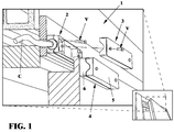
- Said system 1 comprises a first substantially parallelepiped box-like body, consisting of two half-parallelepiped half-shells 2 (being fixed to the window jamb) and 3, which may be removably coupled by screws V, and designed for containing, in a coupled condition, the magnetic sensor means S - ( Fig. 2 ).
- Figure 1 also shows the second box-like body 4, also constituted by two half-parallelepiped half-shells 5 and 6, being removably coupled by coupling screws and designed to contain one or more magnets M - ( Fig. 2 ).
- the two containers or housings 2 and 3 are mounted on a window jamb.
- Figures 1A and 1B show two possible arrangements of the container bodies 1 and 2, that is a parallel substantially horizontal position, at a small distance from one another - ( Fig. 1A ) - whereas Figure 1B shows those same two containers in a parallel substantially vertical position, at a same substantially small distance from one another.
- Figures 1C and 1D show, on the contrary, two wrong assembling or mounting positions.
- Figure 2 shows a further perspective view of the two containers or box-like elements 2 and 4 operatively coupled to one another, the window jamb supporting them being not shown.
- Figure 3 shows an electronic card S', constituting the main aspect of the present invention, supporting, on the left of the figure, a magnetic rotary position sensor 7 and, on the right of the figure, a HALL sensor 8.
- said card does not comprise conventional Reed switches.
- inventive method and system have been designed starting from the finding by the Applicant of a sensor, specifically a magnetic rotary position sensor, which may be used, as found by the Applicant, either individually or in combination with the above mentioned HALL effect sensor, for making a magnetic contact adapted for application in door or window anti-intrusion systems.
- a sensor specifically a magnetic rotary position sensor, which may be used, as found by the Applicant, either individually or in combination with the above mentioned HALL effect sensor, for making a magnetic contact adapted for application in door or window anti-intrusion systems.
- Such a magnetic rotary position sensor is, for example, the AS5600 model by the Austrian company AMS AG, which is substantially a programmable contactless potentiometer of a 12-bit type, which, if arranged at a distance of some millimeters from a magnet, is adapted to measure the North/South orientation of the magnetic field generated by the magnet, with a 0.176 degree resolution (for example in case the magnetic field is oriented with an inclination of 0°, the sensor will provide a value 0, at 180° a value 1023 and so on, thereby through 360° the resolution will be of 2048 dots or points).
- the senor S and magnet M are arranged at a sufficiently small distance, then the sensor will be able of detecting, in addition to the orientation, also the magnetic field strength.
- the electronic card of Figure 3 is mounted in the "sensor part" (S) of the magnetic contact of Figure 2 , whereas the magnet or magnets are mounted on the magnet part (M) of Figure 2 .
- the card S' will comprise only the magnetic rotary position sensor 7, whereas, for larger distances, said card will further comprise, in addition to the magnetic sensor 7, also the HALL effect sensor 8.
- the electronic card S' advantageously comprises a microcontroller (not shown) which continuously reads the values recorded instant by instant by the magnetic rotary position sensor 7, thereby, if a variation of the magnetic field orientation compared to a rest condition is recorded, then said microcontroller will generate an alarm which, being sent to a central control unit (not shown), will provide a possibility of performing proper anti-intrusion measures.
- the electronic card S' also comprises the HALL effect sensor, then by the latter sensor it will be possible also to record the magnetic field strength, thereby, also in this case, a variation of the magnetic field strength compared to a rest condition will generate an alarm.
- container materials a die-cast metal; a white epoxidic painting; NC (normally closed) operation with the two components M and S being arranged near one another; an operating temperature from -25°C to + 60°C; protection degree; VMAX 42.4; peak -60 Vdc; I MAX 300 mA; VMAX 3 W; identification of serial number / batch on each component.
- the invention has provided a novel method for using a detection of a magnetic field orientation modification as an alarm source, for an application in the form of a "magnetic contact”.
- a use of the above detection of the magnetic field orientation also provides a possibility of coding the magnetic contact "sensor part” / "magnetic part” pair.
Landscapes
- Physics & Mathematics (AREA)
- General Physics & Mathematics (AREA)
- Engineering & Computer Science (AREA)
- Computer Security & Cryptography (AREA)
- Burglar Alarm Systems (AREA)
Abstract
Description
- The present invention relates to an anti-intrusion detecting method to be applied to doors or windows and a related anti-intrusion system for carrying out the inventive method.
- A broad range of anti-intrusion systems for detecting a door or window opening, and using magnetic contacts as proximity sensors, detecting a magnetic field generated by a permanent magnet mounted on a door or window wing, are available on the market.
- The magnetic contacts used in prior anti-intrusion methods and systems use, as sensitive or sensing elements, Reed contacts, that is blade switch assemblies, which are closed in presence of a magnetic field.
- The Reed switch is housed in a respective casing or small tight tube, to which is operatively coupled a cable communicating with an alarm central unit, whereas the magnet is housed in a dedicated housing, thereby, as the Reed sensor and magnet are arranged near one another, the Reed contact is closed whereas, as the magnet is moved away from the sensor, for example upon attempting to tamper the door and/or window, the Reed contact is opened, thereby signaling an alarm condition to the central unit the Reed contact is connected to.
- A main drawback of the Reed sensors is that they may be easily tampered, for example by putting outer magnets near said Reed sensors, to prevent the latter from switching to an alarm condition.
- Moreover, to meet the European Rules defining safety degrees of an anti-intrusion system based on Reed switches, it is necessary to use a plurality of Reeds within the sensor part, and a corresponding plurality of magnets in the magnet part, in which the positions of the Reed-magnet couplings change from a pair of contacts to another pair of contacts, the different contact pairs being not interchangeable.
- This causes the circuitry pattern to be very complex, and the reliability of the overall system is disadvantageously decreased, whilst the system cost is undesirably increased.
- With respect to the above mentioned European Rules, it should be pointed out that European Standard 50131-1 defines 4 safety degrees for anti-intrusion systems and related components, magnetic contacts included, defining the performance thereof.
- The
degree 1 is the lowest one, whereas thedegree 4 is the highest one. - More specifically, the above mentioned European Standard 50131-2-6 defines the prescribed parameters for magnetic contacts and establishes the requirements which must be met to assign a given safety degree to a magnetic contact.
- Said European Standard moreover provides that: "A magnetic contact of
degree 4 must be constituted by an adapted pair formed by a switching component and a corresponding magnet. The fitting or matching means should comprise at least eight coding variables. It should not be possible to determine an identity of a specific pair by an examination at sight of the detecting device.". - As said above, currently available magnetic contacts of
degree 4 provide a ciphering or coding by using a plurality of Reeds within the sensor part (S) and a plurality of magnets within the magnet part (M), and the positions of the "Reed-magnet" combinations will change from contact pair to contact pair, thereby providing at least eight different non-interchangeable contact pairs. - Accordingly, the aim of the present invention is to overcome the above mentioned drawbacks of prior door and window anti-intrusions systems using Reed sensors, by providing a very simple, reliable, inexpensive anti-intrusion detecting method and system which not only meet the present European Standards of
degree 4, but also possible more stringent standards. - Within the scope of the above mentioned aim, a main object of the present invention is to provide a door or window anti-intrusion method which may be carried out by using commercially available magnetic sensors, the use of which has never been taught or suggested for an anti-intrusion application to doors or windows, and which could not be obviously deduced by one skilled in the art knowing the functional properties of the mentioned prior magnetic sensors.
- Another object of the present invention is to provide a door or window anti-intrusion system for carrying out the inventive method, which system may be built based on a simple electronic card, not using Reed sensors, which may be easily mounted in the sensor part of the magnetic contact to operatively cooperate with and adapted to be driven by one or more magnets mounted in the magnet part of the magnetic contact, thereby greatly simplifying the structure of the overall system for an easy installation of any type of doors and/or windows.
- Another object of the present invention is to provide an anti-intrusion system for carrying out the inventive method, including a single card, not using Reed sensors, whose pattern may assume at least two different operating conditions, equally reliable, that is a first more simple operating condition and a second more sophisticated one, depending on a target specific application.
- Another object of the present invention is to provide an anti-intrusion method and system which not only are able of measuring the magnetic field North/South orientation, but are also designed to record the magnetic field strength.
- Yet another object of the present invention is to provide such a method and system of the above indicated type which allow, in building and programming the product in factory, for example, to cipher the "sensor part" and "magnet part" pair to meet the
degree 4 of the above mentioned European Standard 50131-2-6. - According to an aspect of the present invention, the above mentioned aim and objects, as well as yet other objects, which will become more apparent hereinafter, are achieved by a method for detecting door or window intrusions, having the characterizing features of the enclosed method claims.
- According to a further aspect of the present invention, the above mentioned aim and objects are also achieved by an anti-intrusion system for carrying out the inventive method, said system having the characterizing features of the enclosed system claims.
- Further characteristics and advantages of the method and system of the present invention will become more apparent hereinafter from the following detailed disclosure of a currently preferred embodiment thereof, which is illustrated, by way of an indicative but not limitative example, in the accompanying drawings, where:
-
Figure 1 is a schematic perspective view, on a reduced scale, of the inventive system being applied to a window jamb; -
Figures 1A to 1D show different arrangement modes for arranging the two box-like containers or housings according to the present invention,Figures 1A and 1B showing proper mounting positions, andFigures 1C and 1D showing wrong mounting positions; -
Figure 2 is a further perspective partial view, on a reduced scale, of the two containers S (containing the sensor means according to the invention) and M (containing one or more magnets) of the system according to the invention; and -
Figure 3 shows a partial perspective view, on an enlarged scale compared to the preceding figures, of an electronic card included in the anti-intrusion system according to the present invention and constituting the core of the invention. - With reference to the above mentioned figures and, in particular, to
Figure 1 , the anti-intrusion system according to the present invention, operating based on the inventive method, has been generally indicated by thereference number 1. - Said
system 1 comprises a first substantially parallelepiped box-like body, consisting of two half-parallelepiped half-shells 2 (being fixed to the window jamb) and 3, which may be removably coupled by screws V, and designed for containing, in a coupled condition, the magnetic sensor means S - (Fig. 2 ). -
Figure 1 also shows the second box-like body 4, also constituted by two half-parallelepiped half-shells Fig. 2 ). - From the half-
shell 2 extends a cable C coupled to a control and alarm central unit, not shown. - As illustrated, the two containers or
housings -
Figures 1A and 1B show two possible arrangements of thecontainer bodies Fig. 1A ) - whereasFigure 1B shows those same two containers in a parallel substantially vertical position, at a same substantially small distance from one another. - The arrangements shown in
Figure 1A and Figure 1B represent proper assembling or mounting positions. -
Figures 1C and 1D show, on the contrary, two wrong assembling or mounting positions. -
Figure 2 shows a further perspective view of the two containers or box-like elements -
Figure 3 shows an electronic card S', constituting the main aspect of the present invention, supporting, on the left of the figure, a magneticrotary position sensor 7 and, on the right of the figure, aHALL sensor 8. - Thus, said card does not comprise conventional Reed switches.
- In this connection it should be apparent that, even though the use of HALL effect sensors for detecting a presence of magnetic fields is well known, however, the Applicant, to the best of his knowledge, is not aware of any door or window anti-intrusion system using a HALL effect sensor for detecting the North/South orientation of the magnetic field.
- In particular, the inventive method and system have been designed starting from the finding by the Applicant of a sensor, specifically a magnetic rotary position sensor, which may be used, as found by the Applicant, either individually or in combination with the above mentioned HALL effect sensor, for making a magnetic contact adapted for application in door or window anti-intrusion systems.
- Such a magnetic rotary position sensor is, for example, the AS5600 model by the Austrian company AMS AG, which is substantially a programmable contactless potentiometer of a 12-bit type, which, if arranged at a distance of some millimeters from a magnet, is adapted to measure the North/South orientation of the magnetic field generated by the magnet, with a 0.176 degree resolution (for example in case the magnetic field is oriented with an inclination of 0°, the sensor will provide a value 0, at 180° a value 1023 and so on, thereby through 360° the resolution will be of 2048 dots or points).
- If the sensor S and magnet M are arranged at a sufficiently small distance, then the sensor will be able of detecting, in addition to the orientation, also the magnetic field strength.
- The electronic card of
Figure 3 , generally indicated by the reference letter S', constituting, as mentioned above, the core of the present invention, is mounted in the "sensor part" (S) of the magnetic contact ofFigure 2 , whereas the magnet or magnets are mounted on the magnet part (M) ofFigure 2 . - In case the magnetic contact is used for very small operating distances, the card S' will comprise only the magnetic
rotary position sensor 7, whereas, for larger distances, said card will further comprise, in addition to themagnetic sensor 7, also theHALL effect sensor 8. - The electronic card S' advantageously comprises a microcontroller (not shown) which continuously reads the values recorded instant by instant by the magnetic
rotary position sensor 7, thereby, if a variation of the magnetic field orientation compared to a rest condition is recorded, then said microcontroller will generate an alarm which, being sent to a central control unit (not shown), will provide a possibility of performing proper anti-intrusion measures. - Vice-versa, if the electronic card S' also comprises the HALL effect sensor, then by the latter sensor it will be possible also to record the magnetic field strength, thereby, also in this case, a variation of the magnetic field strength compared to a rest condition will generate an alarm.
- Moreover, by suitably mounting and orienting a magnet in the magnet part (M) of the magnetic contact, it will be possible, as the system is built and programmed in factory, to cipher or code the "sensor part" (S) and "magnet part" (M) pair to meet the
degree 4 of the European Standard EN50131-2-6. - Finally, it should be pointed out that an actual embodiment of the inventive system was provided with the following general specifics: container materials: a die-cast metal; a white epoxidic painting; NC (normally closed) operation with the two components M and S being arranged near one another; an operating temperature from -25°C to + 60°C; protection degree; VMAX 42.4; peak -60 Vdc; I MAX 300 mA; VMAX 3 W; identification of serial number / batch on each component.
- From the above disclosure it should be apparent that the invention fully achieves the intended aim and objects.
- In fact, the invention has provided a novel method for using a detection of a magnetic field orientation modification as an alarm source, for an application in the form of a "magnetic contact".
- A use of the above detection of the magnetic field orientation also provides a possibility of coding the magnetic contact "sensor part" / "magnetic part" pair.
- Although the invention has been disclosed with reference to a currently preferred embodiment thereof, it should be apparent that the disclosed embodiment is susceptible to several modifications and variations, all coming within the invention scope as defined in the appended claims.
Claims (7)
- An anti-intrusion detecting system, to be applied to a door or a window for generating an alarm condition as said door or window is moved away from a preset closed position thereof, to said door or window being applied magnetic field generating means and magnetic field sensing means, said magnetic field generating means and said magnetic field sensing means constituting a pair of a magnetic field generator part and a magnetic field sensor part, characterized in that said system comprises an electronic microcontroller card mounted in said sensor part and at least a magnet mounted in said magnet part, said card including moreover said magnetic field sensing or sensor means, said magnetic field sensing means including at least a magnetic rotary position sensor adapted to detect a North/South orientation of said magnetic field, thereby a variation of said orientation of said magnetic field compared to a rest condition is adapted to generate an alarm, and in that said electronic card comprises a microcontroller which continuously reads the values recorded instant by instant by the magnetic rotary position sensor, thereby, if a variation of the magnetic field orientation compared to the rest condition is recorded, the microcontroller will generate an alarm which, being sent to a central unit, will provide a possibility of performing proper anti-intrusion measures.
- A system, according to claim 1, characterized in that said magnetic field sensing means comprise moreover a HALL effect sensor adapted to record the magnetic field strength, thereby at least one of said magnetic field orientation variation and/or said variation compared to a rest condition of the magnetic field strength compared to said rest condition will generate an alarm.
- A system, according to claims 1 and 2, characterized in that said magnetic rotary position sensor is a 12-bit programmable contactless potentiometric sensor.
- A system, according to claims 1 to 3, characterized in that said system measures a North/South orientation of said magnetic field with a measuring resolution of substantially 0.176 degrees.
- A system, according to any of the preceding claims, characterized in that said system meets the anti-intrusion safety rules of the European Standard 50131-1 of a degree 4 and higher.
- A system, according to claims 1 to 5, characterized in that said magnet part and said sensor part are mounted in substantially parallelepiped metal containers.
- A system, according to claims 1 to 6, characterized in that said system is mounted according to standard mounting rules and has substantially the following general specifics:containers: a die-cast metal, an epoxidic painting, a NC (normally closed) operation with the two containers near one another;an operating temperature from -25 °C to +60 °C;VMAX: 42.4; Vpeak -60Vdc; IMAX 300 mA; VMAX 3W; identification of serial number / batch on each component.
Applications Claiming Priority (1)
| Application Number | Priority Date | Filing Date | Title |
|---|---|---|---|
| ITUB20151495 | 2015-06-18 |
Publications (2)
| Publication Number | Publication Date |
|---|---|
| EP3107077A1 true EP3107077A1 (en) | 2016-12-21 |
| EP3107077B1 EP3107077B1 (en) | 2020-02-19 |
Family
ID=54199954
Family Applications (1)
| Application Number | Title | Priority Date | Filing Date |
|---|---|---|---|
| EP16020233.9A Active EP3107077B1 (en) | 2015-06-18 | 2016-06-17 | Anti-intrusion detecting method to be applied to doors or windows and related anti-intrusion system |
Country Status (1)
| Country | Link |
|---|---|
| EP (1) | EP3107077B1 (en) |
Cited By (2)
| Publication number | Priority date | Publication date | Assignee | Title |
|---|---|---|---|---|
| US10755554B2 (en) | 2018-09-28 | 2020-08-25 | Nortek Security & Control Llc | Vector magnetic tamper detection for sensors |
| US11397096B2 (en) | 2018-10-31 | 2022-07-26 | Assa Abloy Ab | Determining an extent of opening of an openable barrier based on a magnetic sensor |
Citations (3)
| Publication number | Priority date | Publication date | Assignee | Title |
|---|---|---|---|---|
| EP2650848A2 (en) * | 2012-04-09 | 2013-10-16 | Honeywell International Inc. | Large gap door/window, high security, intrusion detectors using magnetometers |
| EP2711905A2 (en) * | 2012-09-21 | 2014-03-26 | Link GmbH | Reporting system |
| WO2014138776A1 (en) * | 2013-03-12 | 2014-09-18 | Fire & Security Hardware Pty Ltd | A position monitoring device |
-
2016
- 2016-06-17 EP EP16020233.9A patent/EP3107077B1/en active Active
Patent Citations (3)
| Publication number | Priority date | Publication date | Assignee | Title |
|---|---|---|---|---|
| EP2650848A2 (en) * | 2012-04-09 | 2013-10-16 | Honeywell International Inc. | Large gap door/window, high security, intrusion detectors using magnetometers |
| EP2711905A2 (en) * | 2012-09-21 | 2014-03-26 | Link GmbH | Reporting system |
| WO2014138776A1 (en) * | 2013-03-12 | 2014-09-18 | Fire & Security Hardware Pty Ltd | A position monitoring device |
Non-Patent Citations (1)
| Title |
|---|
| UNKNOWN: "3-Axis Digital Compass IC HMC5983", 31 January 2012 (2012-01-31), XP055312064, Retrieved from the Internet <URL:http://aerocontent.honeywell.com/aero/common/documents/myaerospacecatalog-documents/Defense_Brochures-documents/HMC5983_3_Axis_Compass_IC.pdf> [retrieved on 20161019] * |
Cited By (3)
| Publication number | Priority date | Publication date | Assignee | Title |
|---|---|---|---|---|
| US10755554B2 (en) | 2018-09-28 | 2020-08-25 | Nortek Security & Control Llc | Vector magnetic tamper detection for sensors |
| US11282373B2 (en) | 2018-09-28 | 2022-03-22 | Nortek Security & Control Llc | Vector magnetic tamper detection for sensors |
| US11397096B2 (en) | 2018-10-31 | 2022-07-26 | Assa Abloy Ab | Determining an extent of opening of an openable barrier based on a magnetic sensor |
Also Published As
| Publication number | Publication date |
|---|---|
| EP3107077B1 (en) | 2020-02-19 |
Similar Documents
| Publication | Publication Date | Title |
|---|---|---|
| US10488464B2 (en) | Magnetic sensor circuit for security sensing | |
| CN108475459B (en) | Door/window magnetic sensing apparatus and method of installation | |
| US8970373B2 (en) | Large gap door/window, high security, intrusion detectors using magnetometers | |
| US4296410A (en) | Two-state Hall element proximity sensor device with lamp indicator | |
| US20220049975A1 (en) | Position monitoring device and method | |
| US3161742A (en) | Magnetic intruder and fire deterctor | |
| EP3881300B1 (en) | Contact sensor with masking detection feature | |
| ES2730204T3 (en) | Signaling system | |
| EP3107077B1 (en) | Anti-intrusion detecting method to be applied to doors or windows and related anti-intrusion system | |
| US20160086482A1 (en) | Inductive security sensor not susceptible to magnetic tampering | |
| US8699200B2 (en) | Secure non-contact switch | |
| KR200300365Y1 (en) | Door locking system for monitoring door to be opened and closed | |
| EP2590197B1 (en) | Magnetic sensor designed to operate with a corresponding magnet and magnetic contact comprising said magnetic sensor and corresponding magnet | |
| GB2450890A (en) | Magnetic contact | |
| CN210091323U (en) | A magnetic induction position monitoring device | |
| JP2015191511A (en) | magnetic detection sensor | |
| US20230259376A1 (en) | Gate Operator with Context Sensitive QR Code | |
| US11828624B1 (en) | Proximity sensing components employing enhanced security communications | |
| US9305443B2 (en) | LED security sensor | |
| EP4632708A1 (en) | A method for detecting a sabotage magnetic field and a closing/opening sensor for performing the method (variants) | |
| US9852863B2 (en) | Safety switch for monitoring an access of an automation system comprising a stationary part and a movable part | |
| EP3663490A1 (en) | Opening apparatus, door opening arrangement and related method | |
| ATE126378T1 (en) | DEVICE FOR REPORTING THE OPENING AND CLOSING POSITION OF LOCKABLE ELEMENTS. | |
| US8797130B2 (en) | Universally orientable security switch |
Legal Events
| Date | Code | Title | Description |
|---|---|---|---|
| PUAI | Public reference made under article 153(3) epc to a published international application that has entered the european phase |
Free format text: ORIGINAL CODE: 0009012 |
|
| STAA | Information on the status of an ep patent application or granted ep patent |
Free format text: STATUS: THE APPLICATION HAS BEEN PUBLISHED |
|
| AK | Designated contracting states |
Kind code of ref document: A1 Designated state(s): AL AT BE BG CH CY CZ DE DK EE ES FI FR GB GR HR HU IE IS IT LI LT LU LV MC MK MT NL NO PL PT RO RS SE SI SK SM TR |
|
| AX | Request for extension of the european patent |
Extension state: BA ME |
|
| STAA | Information on the status of an ep patent application or granted ep patent |
Free format text: STATUS: REQUEST FOR EXAMINATION WAS MADE |
|
| 17P | Request for examination filed |
Effective date: 20170620 |
|
| GRAP | Despatch of communication of intention to grant a patent |
Free format text: ORIGINAL CODE: EPIDOSNIGR1 |
|
| STAA | Information on the status of an ep patent application or granted ep patent |
Free format text: STATUS: GRANT OF PATENT IS INTENDED |
|
| INTG | Intention to grant announced |
Effective date: 20190724 |
|
| RIN1 | Information on inventor provided before grant (corrected) |
Inventor name: GARGIULO, FRANCO |
|
| GRAS | Grant fee paid |
Free format text: ORIGINAL CODE: EPIDOSNIGR3 |
|
| GRAA | (expected) grant |
Free format text: ORIGINAL CODE: 0009210 |
|
| STAA | Information on the status of an ep patent application or granted ep patent |
Free format text: STATUS: THE PATENT HAS BEEN GRANTED |
|
| AK | Designated contracting states |
Kind code of ref document: B1 Designated state(s): AL AT BE BG CH CY CZ DE DK EE ES FI FR GB GR HR HU IE IS IT LI LT LU LV MC MK MT NL NO PL PT RO RS SE SI SK SM TR |
|
| REG | Reference to a national code |
Ref country code: CH Ref legal event code: EP |
|
| REG | Reference to a national code |
Ref country code: DE Ref legal event code: R096 Ref document number: 602016029885 Country of ref document: DE |
|
| REG | Reference to a national code |
Ref country code: AT Ref legal event code: REF Ref document number: 1235837 Country of ref document: AT Kind code of ref document: T Effective date: 20200315 |
|
| REG | Reference to a national code |
Ref country code: IE Ref legal event code: FG4D |
|
| REG | Reference to a national code |
Ref country code: NL Ref legal event code: MP Effective date: 20200219 |
|
| PG25 | Lapsed in a contracting state [announced via postgrant information from national office to epo] |
Ref country code: NO Free format text: LAPSE BECAUSE OF FAILURE TO SUBMIT A TRANSLATION OF THE DESCRIPTION OR TO PAY THE FEE WITHIN THE PRESCRIBED TIME-LIMIT Effective date: 20200519 Ref country code: RS Free format text: LAPSE BECAUSE OF FAILURE TO SUBMIT A TRANSLATION OF THE DESCRIPTION OR TO PAY THE FEE WITHIN THE PRESCRIBED TIME-LIMIT Effective date: 20200219 Ref country code: FI Free format text: LAPSE BECAUSE OF FAILURE TO SUBMIT A TRANSLATION OF THE DESCRIPTION OR TO PAY THE FEE WITHIN THE PRESCRIBED TIME-LIMIT Effective date: 20200219 |
|
| RAP2 | Party data changed (patent owner data changed or rights of a patent transferred) |
Owner name: EATON INTELLIGENT POWER LIMITED |
|
| REG | Reference to a national code |
Ref country code: LT Ref legal event code: MG4D |
|
| PG25 | Lapsed in a contracting state [announced via postgrant information from national office to epo] |
Ref country code: SE Free format text: LAPSE BECAUSE OF FAILURE TO SUBMIT A TRANSLATION OF THE DESCRIPTION OR TO PAY THE FEE WITHIN THE PRESCRIBED TIME-LIMIT Effective date: 20200219 Ref country code: LV Free format text: LAPSE BECAUSE OF FAILURE TO SUBMIT A TRANSLATION OF THE DESCRIPTION OR TO PAY THE FEE WITHIN THE PRESCRIBED TIME-LIMIT Effective date: 20200219 Ref country code: HR Free format text: LAPSE BECAUSE OF FAILURE TO SUBMIT A TRANSLATION OF THE DESCRIPTION OR TO PAY THE FEE WITHIN THE PRESCRIBED TIME-LIMIT Effective date: 20200219 Ref country code: GR Free format text: LAPSE BECAUSE OF FAILURE TO SUBMIT A TRANSLATION OF THE DESCRIPTION OR TO PAY THE FEE WITHIN THE PRESCRIBED TIME-LIMIT Effective date: 20200520 Ref country code: BG Free format text: LAPSE BECAUSE OF FAILURE TO SUBMIT A TRANSLATION OF THE DESCRIPTION OR TO PAY THE FEE WITHIN THE PRESCRIBED TIME-LIMIT Effective date: 20200519 Ref country code: IS Free format text: LAPSE BECAUSE OF FAILURE TO SUBMIT A TRANSLATION OF THE DESCRIPTION OR TO PAY THE FEE WITHIN THE PRESCRIBED TIME-LIMIT Effective date: 20200619 |
|
| PG25 | Lapsed in a contracting state [announced via postgrant information from national office to epo] |
Ref country code: NL Free format text: LAPSE BECAUSE OF FAILURE TO SUBMIT A TRANSLATION OF THE DESCRIPTION OR TO PAY THE FEE WITHIN THE PRESCRIBED TIME-LIMIT Effective date: 20200219 |
|
| PG25 | Lapsed in a contracting state [announced via postgrant information from national office to epo] |
Ref country code: RO Free format text: LAPSE BECAUSE OF FAILURE TO SUBMIT A TRANSLATION OF THE DESCRIPTION OR TO PAY THE FEE WITHIN THE PRESCRIBED TIME-LIMIT Effective date: 20200219 Ref country code: CZ Free format text: LAPSE BECAUSE OF FAILURE TO SUBMIT A TRANSLATION OF THE DESCRIPTION OR TO PAY THE FEE WITHIN THE PRESCRIBED TIME-LIMIT Effective date: 20200219 Ref country code: PT Free format text: LAPSE BECAUSE OF FAILURE TO SUBMIT A TRANSLATION OF THE DESCRIPTION OR TO PAY THE FEE WITHIN THE PRESCRIBED TIME-LIMIT Effective date: 20200712 Ref country code: SK Free format text: LAPSE BECAUSE OF FAILURE TO SUBMIT A TRANSLATION OF THE DESCRIPTION OR TO PAY THE FEE WITHIN THE PRESCRIBED TIME-LIMIT Effective date: 20200219 Ref country code: ES Free format text: LAPSE BECAUSE OF FAILURE TO SUBMIT A TRANSLATION OF THE DESCRIPTION OR TO PAY THE FEE WITHIN THE PRESCRIBED TIME-LIMIT Effective date: 20200219 Ref country code: LT Free format text: LAPSE BECAUSE OF FAILURE TO SUBMIT A TRANSLATION OF THE DESCRIPTION OR TO PAY THE FEE WITHIN THE PRESCRIBED TIME-LIMIT Effective date: 20200219 Ref country code: DK Free format text: LAPSE BECAUSE OF FAILURE TO SUBMIT A TRANSLATION OF THE DESCRIPTION OR TO PAY THE FEE WITHIN THE PRESCRIBED TIME-LIMIT Effective date: 20200219 Ref country code: EE Free format text: LAPSE BECAUSE OF FAILURE TO SUBMIT A TRANSLATION OF THE DESCRIPTION OR TO PAY THE FEE WITHIN THE PRESCRIBED TIME-LIMIT Effective date: 20200219 Ref country code: SM Free format text: LAPSE BECAUSE OF FAILURE TO SUBMIT A TRANSLATION OF THE DESCRIPTION OR TO PAY THE FEE WITHIN THE PRESCRIBED TIME-LIMIT Effective date: 20200219 |
|
| REG | Reference to a national code |
Ref country code: AT Ref legal event code: MK05 Ref document number: 1235837 Country of ref document: AT Kind code of ref document: T Effective date: 20200219 |
|
| REG | Reference to a national code |
Ref country code: DE Ref legal event code: R097 Ref document number: 602016029885 Country of ref document: DE |
|
| PLBE | No opposition filed within time limit |
Free format text: ORIGINAL CODE: 0009261 |
|
| STAA | Information on the status of an ep patent application or granted ep patent |
Free format text: STATUS: NO OPPOSITION FILED WITHIN TIME LIMIT |
|
| 26N | No opposition filed |
Effective date: 20201120 |
|
| PG25 | Lapsed in a contracting state [announced via postgrant information from national office to epo] |
Ref country code: AT Free format text: LAPSE BECAUSE OF FAILURE TO SUBMIT A TRANSLATION OF THE DESCRIPTION OR TO PAY THE FEE WITHIN THE PRESCRIBED TIME-LIMIT Effective date: 20200219 Ref country code: MC Free format text: LAPSE BECAUSE OF FAILURE TO SUBMIT A TRANSLATION OF THE DESCRIPTION OR TO PAY THE FEE WITHIN THE PRESCRIBED TIME-LIMIT Effective date: 20200219 |
|
| REG | Reference to a national code |
Ref country code: CH Ref legal event code: PL |
|
| PG25 | Lapsed in a contracting state [announced via postgrant information from national office to epo] |
Ref country code: PL Free format text: LAPSE BECAUSE OF FAILURE TO SUBMIT A TRANSLATION OF THE DESCRIPTION OR TO PAY THE FEE WITHIN THE PRESCRIBED TIME-LIMIT Effective date: 20200219 Ref country code: SI Free format text: LAPSE BECAUSE OF FAILURE TO SUBMIT A TRANSLATION OF THE DESCRIPTION OR TO PAY THE FEE WITHIN THE PRESCRIBED TIME-LIMIT Effective date: 20200219 |
|
| PG25 | Lapsed in a contracting state [announced via postgrant information from national office to epo] |
Ref country code: LU Free format text: LAPSE BECAUSE OF NON-PAYMENT OF DUE FEES Effective date: 20200617 |
|
| REG | Reference to a national code |
Ref country code: BE Ref legal event code: MM Effective date: 20200630 |
|
| PG25 | Lapsed in a contracting state [announced via postgrant information from national office to epo] |
Ref country code: LI Free format text: LAPSE BECAUSE OF NON-PAYMENT OF DUE FEES Effective date: 20200630 Ref country code: IE Free format text: LAPSE BECAUSE OF NON-PAYMENT OF DUE FEES Effective date: 20200617 Ref country code: CH Free format text: LAPSE BECAUSE OF NON-PAYMENT OF DUE FEES Effective date: 20200630 |
|
| PG25 | Lapsed in a contracting state [announced via postgrant information from national office to epo] |
Ref country code: BE Free format text: LAPSE BECAUSE OF NON-PAYMENT OF DUE FEES Effective date: 20200630 |
|
| PG25 | Lapsed in a contracting state [announced via postgrant information from national office to epo] |
Ref country code: TR Free format text: LAPSE BECAUSE OF FAILURE TO SUBMIT A TRANSLATION OF THE DESCRIPTION OR TO PAY THE FEE WITHIN THE PRESCRIBED TIME-LIMIT Effective date: 20200219 Ref country code: MT Free format text: LAPSE BECAUSE OF FAILURE TO SUBMIT A TRANSLATION OF THE DESCRIPTION OR TO PAY THE FEE WITHIN THE PRESCRIBED TIME-LIMIT Effective date: 20200219 Ref country code: CY Free format text: LAPSE BECAUSE OF FAILURE TO SUBMIT A TRANSLATION OF THE DESCRIPTION OR TO PAY THE FEE WITHIN THE PRESCRIBED TIME-LIMIT Effective date: 20200219 |
|
| PG25 | Lapsed in a contracting state [announced via postgrant information from national office to epo] |
Ref country code: MK Free format text: LAPSE BECAUSE OF FAILURE TO SUBMIT A TRANSLATION OF THE DESCRIPTION OR TO PAY THE FEE WITHIN THE PRESCRIBED TIME-LIMIT Effective date: 20200219 Ref country code: AL Free format text: LAPSE BECAUSE OF FAILURE TO SUBMIT A TRANSLATION OF THE DESCRIPTION OR TO PAY THE FEE WITHIN THE PRESCRIBED TIME-LIMIT Effective date: 20200219 |
|
| P01 | Opt-out of the competence of the unified patent court (upc) registered |
Effective date: 20230521 |
|
| PGFP | Annual fee paid to national office [announced via postgrant information from national office to epo] |
Ref country code: GB Payment date: 20260520 Year of fee payment: 11 |
|
| PGFP | Annual fee paid to national office [announced via postgrant information from national office to epo] |
Ref country code: IT Payment date: 20260520 Year of fee payment: 11 |
|
| PGFP | Annual fee paid to national office [announced via postgrant information from national office to epo] |
Ref country code: DE Payment date: 20260520 Year of fee payment: 11 |
|
| PGFP | Annual fee paid to national office [announced via postgrant information from national office to epo] |
Ref country code: FR Payment date: 20260520 Year of fee payment: 11 |