EP3106703A1 - Braking device - Google Patents
Braking device Download PDFInfo
- Publication number
- EP3106703A1 EP3106703A1 EP15799881.6A EP15799881A EP3106703A1 EP 3106703 A1 EP3106703 A1 EP 3106703A1 EP 15799881 A EP15799881 A EP 15799881A EP 3106703 A1 EP3106703 A1 EP 3106703A1
- Authority
- EP
- European Patent Office
- Prior art keywords
- brake
- eccentric
- rotation
- portions
- pair
- Prior art date
- Legal status (The legal status is an assumption and is not a legal conclusion. Google has not performed a legal analysis and makes no representation as to the accuracy of the status listed.)
- Withdrawn
Links
Images

Classifications
-
- B—PERFORMING OPERATIONS; TRANSPORTING
- B61—RAILWAYS
- B61H—BRAKES OR OTHER RETARDING DEVICES SPECIALLY ADAPTED FOR RAIL VEHICLES; ARRANGEMENT OR DISPOSITION THEREOF IN RAIL VEHICLES
- B61H5/00—Applications or arrangements of brakes with substantially radial braking surfaces pressed together in axial direction, e.g. disc brakes
-
- F—MECHANICAL ENGINEERING; LIGHTING; HEATING; WEAPONS; BLASTING
- F16—ENGINEERING ELEMENTS AND UNITS; GENERAL MEASURES FOR PRODUCING AND MAINTAINING EFFECTIVE FUNCTIONING OF MACHINES OR INSTALLATIONS; THERMAL INSULATION IN GENERAL
- F16D—COUPLINGS FOR TRANSMITTING ROTATION; CLUTCHES; BRAKES
- F16D55/00—Brakes with substantially-radial braking surfaces pressed together in axial direction, e.g. disc brakes
- F16D55/02—Brakes with substantially-radial braking surfaces pressed together in axial direction, e.g. disc brakes with axially-movable discs or pads pressed against axially-located rotating members
- F16D55/22—Brakes with substantially-radial braking surfaces pressed together in axial direction, e.g. disc brakes with axially-movable discs or pads pressed against axially-located rotating members by clamping an axially-located rotating disc between movable braking members, e.g. movable brake discs or brake pads
- F16D55/224—Brakes with substantially-radial braking surfaces pressed together in axial direction, e.g. disc brakes with axially-movable discs or pads pressed against axially-located rotating members by clamping an axially-located rotating disc between movable braking members, e.g. movable brake discs or brake pads with a common actuating member for the braking members
- F16D55/225—Brakes with substantially-radial braking surfaces pressed together in axial direction, e.g. disc brakes with axially-movable discs or pads pressed against axially-located rotating members by clamping an axially-located rotating disc between movable braking members, e.g. movable brake discs or brake pads with a common actuating member for the braking members the braking members being brake pads
- F16D55/2255—Brakes with substantially-radial braking surfaces pressed together in axial direction, e.g. disc brakes with axially-movable discs or pads pressed against axially-located rotating members by clamping an axially-located rotating disc between movable braking members, e.g. movable brake discs or brake pads with a common actuating member for the braking members the braking members being brake pads in which the common actuating member is pivoted
-
- F—MECHANICAL ENGINEERING; LIGHTING; HEATING; WEAPONS; BLASTING
- F16—ENGINEERING ELEMENTS AND UNITS; GENERAL MEASURES FOR PRODUCING AND MAINTAINING EFFECTIVE FUNCTIONING OF MACHINES OR INSTALLATIONS; THERMAL INSULATION IN GENERAL
- F16D—COUPLINGS FOR TRANSMITTING ROTATION; CLUTCHES; BRAKES
- F16D55/00—Brakes with substantially-radial braking surfaces pressed together in axial direction, e.g. disc brakes
- F16D55/02—Brakes with substantially-radial braking surfaces pressed together in axial direction, e.g. disc brakes with axially-movable discs or pads pressed against axially-located rotating members
- F16D55/22—Brakes with substantially-radial braking surfaces pressed together in axial direction, e.g. disc brakes with axially-movable discs or pads pressed against axially-located rotating members by clamping an axially-located rotating disc between movable braking members, e.g. movable brake discs or brake pads
- F16D55/224—Brakes with substantially-radial braking surfaces pressed together in axial direction, e.g. disc brakes with axially-movable discs or pads pressed against axially-located rotating members by clamping an axially-located rotating disc between movable braking members, e.g. movable brake discs or brake pads with a common actuating member for the braking members
- F16D55/2245—Brakes with substantially-radial braking surfaces pressed together in axial direction, e.g. disc brakes with axially-movable discs or pads pressed against axially-located rotating members by clamping an axially-located rotating disc between movable braking members, e.g. movable brake discs or brake pads with a common actuating member for the braking members in which the common actuating member acts on two levers carrying the braking members, e.g. tong-type brakes
-
- F—MECHANICAL ENGINEERING; LIGHTING; HEATING; WEAPONS; BLASTING
- F16—ENGINEERING ELEMENTS AND UNITS; GENERAL MEASURES FOR PRODUCING AND MAINTAINING EFFECTIVE FUNCTIONING OF MACHINES OR INSTALLATIONS; THERMAL INSULATION IN GENERAL
- F16D—COUPLINGS FOR TRANSMITTING ROTATION; CLUTCHES; BRAKES
- F16D65/00—Parts or details
- F16D65/14—Actuating mechanisms for brakes; Means for initiating operation at a predetermined position
- F16D65/16—Actuating mechanisms for brakes; Means for initiating operation at a predetermined position arranged in or on the brake
- F16D65/18—Actuating mechanisms for brakes; Means for initiating operation at a predetermined position arranged in or on the brake adapted for drawing members together, e.g. for disc brakes
-
- F—MECHANICAL ENGINEERING; LIGHTING; HEATING; WEAPONS; BLASTING
- F16—ENGINEERING ELEMENTS AND UNITS; GENERAL MEASURES FOR PRODUCING AND MAINTAINING EFFECTIVE FUNCTIONING OF MACHINES OR INSTALLATIONS; THERMAL INSULATION IN GENERAL
- F16D—COUPLINGS FOR TRANSMITTING ROTATION; CLUTCHES; BRAKES
- F16D2125/00—Components of actuators
- F16D2125/18—Mechanical mechanisms
- F16D2125/20—Mechanical mechanisms converting rotation to linear movement or vice versa
- F16D2125/22—Mechanical mechanisms converting rotation to linear movement or vice versa acting transversely to the axis of rotation
- F16D2125/28—Cams; Levers with cams
-
- F—MECHANICAL ENGINEERING; LIGHTING; HEATING; WEAPONS; BLASTING
- F16—ENGINEERING ELEMENTS AND UNITS; GENERAL MEASURES FOR PRODUCING AND MAINTAINING EFFECTIVE FUNCTIONING OF MACHINES OR INSTALLATIONS; THERMAL INSULATION IN GENERAL
- F16D—COUPLINGS FOR TRANSMITTING ROTATION; CLUTCHES; BRAKES
- F16D2125/00—Components of actuators
- F16D2125/18—Mechanical mechanisms
- F16D2125/58—Mechanical mechanisms transmitting linear movement
- F16D2125/64—Levers
Definitions
- a brake apparatus which brakes the rotation of a wheel by causing a force by an actuator to act on points of force of a pair of link arms rotatable about fulcrums and causing brake linings supported on points of action of the link arms to slide in contact with brake discs.
- JP10-505038A discloses a brake caliper unit in which one end parts of caliper levers are coupled to each other, the other end parts are respectively rotationally mounted on brake pads and an eccentric body transmission device provided on a fulcrum between the both end parts of the caliper lever rotates the caliper levers.
- the eccentric body transmission device includes an eccentric pin configured to rotate by receiving a force by a braking force generator and rotates the caliper lever about the one end part by the rotation of this eccentric pin.
- a brake apparatus for braking by sandwiching a brake disc rotating together with a wheel, includes a brake main body supported on a vehicle body or a truck; an actuator provided on the brake main body and configured to advance and retract an output member; a pair of link arms having supporting portions between one and other end parts rotatably supported on the brake main body, the pair of link arms being respectively provided to face both surfaces of the brake discs, the pair of link arms having the one end parts coupled by a coupling rod and configured such that the other end parts respectively support brake linings for giving a frictional force by sliding in contact with the brake discs; a lever rotatably coupled to the output member of the actuator and configured to rotate by advancing and retracting movements of the output member; and a booster unit provided on at least one of the one end parts of the pair of link arms and configured to rotate the link arms with the supporting portions as fulcrums by boosting a force transmitted by the rotation of the lever.
- the brake apparatus 100 is mainly applied to railway vehicles.
- the brake apparatus 100 brakes a wheel 1 by sandwiching brake discs 1a rotating together with the wheel 1.
- the brake apparatus 100 brakes the rotation of the wheel 1 by frictional forces between the brake discs 1a and brake linings 2 by sandwiching the brake discs 1a from opposite sides by a pair of brake linings 2.
- the brake discs 1a are formed on both sides of the wheel 1 and integrally rotate with the wheel 1. Instead of a configuration in which the brake discs 1a are integrally formed with the wheel 1, separate brake discs 1a configured to rotate together with the wheel 1 may be provided.
- the brake lining 2 faces the brake disc 1a with a predetermined interval set in advance therebetween (state shown in FIG. 1 ).
- the brake lining 2 moves toward the brake disc 1a and is pressed into contact with the brake disc 1a in parallel during braking.
- the actuator 20 is a fluid pressure actuator configured to be operated by a liquid pressure such as a hydraulic pressure or a pressure of working fluid such as a pneumatic pressure. Without limitation to this, the actuator 20 may be of another type such as a mechanical actuator configured to be operated by the rotation of an electric motor. The actuator 20 operates based on a braking operation of a driver and advances and retracts the rod 21 relative to the brake main body 10.
- the rod 21 includes a coupling shaft 22, to which the levers 40 are respectively rotatably coupled, on both end parts.
- the coupling shaft 22 is so arranged that a center axis thereof is parallel to the brake linings 2. Centers of the brake discs 1a are located on an extension of a center axis along which the rod 21 reciprocates.
- the rod 21 can be advanced and retracted relative to the brake main body 10 and swing in a movable direction of the brake linings 2 (vertical direction in FIG. 1 ).
- the link arms 30 are respectively provided to face both surfaces of the brake discs 1a.
- the one end parts 31 of the pair of link arms 30 are coupled by a coupling rod 35.
- the other end parts 33 of the link arms 30 swingably support the brake linings 2 configured to give frictional forces by sliding in contact with the brake discs 1a.
- the link arm 30 is formed into a substantially U shape having a pair of arm portions 30a provided on upper and lower sides.
- a coupling shaft 31a coupling the coupling rod 35 and the link arm 30 by penetrating therethrough is provided on the one end part 31 of one link arm 30.
- the booster units 50 may be provided on both the one end part 31 of the one link arm 30 and the one end part 31 of the other link arm 30. In that case, each booster unit 50 can rotate each of the one and other link arms 30. The booster unit 50 is described in detail later.
- An arm shaft 32a coupling the link arm 30 and the brake main body 10 by penetrating therethrough is provided on the supporting portion 32 of the link arm 30.
- the link arm 30 is rotatably supported on the brake main body 10 by the arm shaft 32a.
- a circumferential tangential force acting on the brake lining 2 from the brake disc 1a during the braking of the brake apparatus 100 acts on the brake main body 10 via the arm shaft 32a from the supporting portion 32.
- a lining shaft 33a coupling the link arm 30 and the lining holding portion 3 by penetrating therethrough is provided on the other end part 33 of the link arm 30.
- the lining holding portion 3 is rotatably supported on the link arm 30 by the lining shaft 33a. In this way, the brake lining 2 is made swingable relative to the link arm 30 and can constantly come into contact with the brake disc 1a in parallel during braking.
- the levers 40 transmit the force by advancing and retracting movements of the rod 21 of the actuator 20 to the booster unit 50.
- One end part 41 of the lever 40 is rotatably coupled to the coupling shaft 22 of the rod 21.
- Another end part 42 of the lever 40 is unrotatably coupled to a later-described eccentric portion 53 of the booster unit 50.
- the lever 40 rotates between the coupling shaft 22 and the eccentric portion 53 when the rod 21 is advanced and retracted relative to the brake main body 10.
- the lever 40 rotates to a position where it is parallel to the coupling rod 35 in a state where the rod 21 is most retracted from the brake main body 10.
- the eccentric cam 51 includes a large-diameter portion 52 rotatably coupled to the coupling rod 35, the eccentric portions 53 having a center axis A2 at a position offset from the axis of rotation A1 of the eccentric cam 51 and configured to rotate along an arcuate path centered on the axis of rotation A1 by the rotation of the levers 40 and a pair of arm coupling portions 54 formed coaxially with the eccentric portions 53 and rotatably supported on the link arm 30.
- the large-diameter portion 52 is formed to have the same outer diameter as the coupling shaft 31a.
- a center axis of the large-diameter portion 52 is the axis of rotation A1 of the eccentric cam 51.
- the eccentric portions 53 are formed to have a smaller diameter than the large-diameter portion 52.
- the eccentric portions 53 are respectively provided at opposite axial sides of the large-diameter portion 52.
- the levers 40 are relatively unrotatably coupled to the eccentric portions 53.
- the eccentric cam 51 includes the large-diameter portion 52 in a center, the eccentric portions 53 having a smaller diameter than the large-diameter portions 52 at opposite ends thereof and the arm coupling portions 54 having a diameter equal to or smaller than the eccentric portions 53 at further opposite ends thereof.
- the eccentric cam 51 is narrowed in diameter in a stepwise manner from the center toward the opposite end parts, wherefore processing is easy. Further, since the coupling rod 35, the levers 40 and the link arm 30 can be successively assembled with the eccentric cam 51, assemblability is good.
- the brake apparatus 100 enters a braking state from a non-braking state (state shown in FIGS. 1 and 2 ) when the actuator 20 operates based on a braking operation of the driver.
- the link arms 30 are rotatably supported on the brake main body 10 by the supporting portions 32, if the one end parts 31 move in the directions to separate from each other, the other end parts 33 move in directions to approach each other.
- the brake linings 2 move toward the brake discs 1a and are pressed into contact with the brake discs 1a in parallel to brake the rotation of the wheel 1.
- a force transmitted from the rod 21 via the levers 40 is boosted by a factor of L1/L2 and transmitted to the link arms 30 by a lever ratio of a distance L1 between an axis of rotation A3 of the coupling shaft 22 and the axis of rotation A1 and a distance L2 between the axis of rotation A1 and the center axis A2 of the eccentric portions 53.
- a large braking force can be obtained without providing a large-size actuator. Therefore, a size and weight reduction of the brake apparatus 100 is possible.
- the supporting portion 32 of the link arm 30 between the one and other end parts 31, 33 is rotatably supported on the brake main body 10.
- the eccentric cam 51 configured to rotate the link arms 30 by boosting the force transmitted to the rod 21 by the rotation of the levers 40 is provided on the one end part 31 of the link arm 30.
- the circumferential tangential forces acting on the brake linings 2 from the brake discs 1a during the braking of the brake apparatus 100 act on the arm shafts 32a of the supporting portions 32 and do not act on the eccentric cam 51.
- frictional resistance when the eccentric cam 51 rotates does not become large, wherefore machine efficiency during the braking of the brake apparatus 100 can be improved.
- the force transmitted from the rod 21 of the actuator 20 via the levers 40 by the eccentric cam 51 is boosted by a large factor.
- a sufficiently large braking force can be obtained even if the link arms 30 are shortened to reduce the distance L3 for a size and weight reduction of the brake apparatus 100.
- a degree of design freedom of the positions of the arm shafts 32a of the supporting portions 32 is increased by providing the eccentric cam 51 on the one end part 31 of the link arm 30.
- the arm shafts 32a at positions facing a side surface of the wheel 1. Therefore, the distance L3 can be made longer than the distance L4 and the brake linings 2 can be pressed against the brake discs 1a by further boosting the force boosted by the eccentric cam 51.
- the brake apparatus 100 enters the non-braking state (state shown in FIGS. 1 and 2 ) from the braking state when the actuator 20 operates in a direction opposite to that during braking based on a brake releasing operation of the driver.
- the eccentric cam 51 rotates in the other direction (clockwise direction in FIG. 1 ) by the rotation of the eccentric portions 53 along the arcuate paths centered on the axis of rotation A1 due to the force transmitted via the levers 40.
- This causes the one end parts 31 of the pair of link arms 30 to move in directions to approach each other.
- the other end parts 33 of the pair of link arms 30 move in directions to separate from each other. In this way, the brake linings 2 are separated from the brake discs 1a to release the braking of the wheel 1.
Landscapes
- Engineering & Computer Science (AREA)
- General Engineering & Computer Science (AREA)
- Mechanical Engineering (AREA)
- Braking Arrangements (AREA)
Abstract
Description
- The present invention relates to a brake apparatus.
- Conventionally, a brake apparatus has been used which brakes the rotation of a wheel by causing a force by an actuator to act on points of force of a pair of link arms rotatable about fulcrums and causing brake linings supported on points of action of the link arms to slide in contact with brake discs.
-
JP10-505038A - However, in the caliper brake unit of
JP10-505038A - The present invention aims to improve the machine efficiency of a brake apparatus.
- According to one aspect of the present invention, a brake apparatus for braking by sandwiching a brake disc rotating together with a wheel, includes a brake main body supported on a vehicle body or a truck; an actuator provided on the brake main body and configured to advance and retract an output member; a pair of link arms having supporting portions between one and other end parts rotatably supported on the brake main body, the pair of link arms being respectively provided to face both surfaces of the brake discs, the pair of link arms having the one end parts coupled by a coupling rod and configured such that the other end parts respectively support brake linings for giving a frictional force by sliding in contact with the brake discs; a lever rotatably coupled to the output member of the actuator and configured to rotate by advancing and retracting movements of the output member; and a booster unit provided on at least one of the one end parts of the pair of link arms and configured to rotate the link arms with the supporting portions as fulcrums by boosting a force transmitted by the rotation of the lever.
-
-
FIG. 1 is a plan view of a brake apparatus according to an embodiment of the present invention, and -
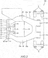
FIG. 2 is a front view of the brake apparatus according to the embodiment of the present invention. - Hereinafter, an embodiment of the present invention is described with reference to the drawings.
- First, the configuration of a
brake apparatus 100 according to the embodiment of the present invention is described with reference toFIGS.1 and2 . - The
brake apparatus 100 is mainly applied to railway vehicles. Thebrake apparatus 100 brakes awheel 1 by sandwichingbrake discs 1a rotating together with thewheel 1. Specifically, thebrake apparatus 100 brakes the rotation of thewheel 1 by frictional forces between thebrake discs 1a andbrake linings 2 by sandwiching thebrake discs 1a from opposite sides by a pair ofbrake linings 2. - The
brake discs 1a are formed on both sides of thewheel 1 and integrally rotate with thewheel 1. Instead of a configuration in which thebrake discs 1a are integrally formed with thewheel 1,separate brake discs 1a configured to rotate together with thewheel 1 may be provided. - The
brake lining 2 faces thebrake disc 1a with a predetermined interval set in advance therebetween (state shown inFIG. 1 ). Thebrake lining 2 moves toward thebrake disc 1a and is pressed into contact with thebrake disc 1a in parallel during braking. - The
brake lining 2 includes aback plate portion 2a supported on alining holding portion 3 of thebrake apparatus 100 and afriction member 2b configured to come into contact with thebrake disc 1a during braking. Thefriction member 2b is composed of a plurality of segments and fixed to a surface of theback plate portion 2a. The brake lining 2 brakes the rotation of thewheel 1 by a frictional force generated by the contact of thefriction member 2b and thebrake disc 1a. - The
lining holding portion 3 includes dovetail grooves (not shown) into which theback plate portions 2a of thebrake linings 2 are to be inserted. Anchor blocks 4 fixed to thelining holding portion 3 are respectively provided on upper and lower end parts of thelining holding portion 3 by a pair ofanchor bolts 5. The anchor blocks 4 fix end parts of theback plate portions 2a of thebrake linings 2 in a longitudinal direction (vertical direction inFIG. 2 ). This causes thebrake linings 2 inserted into the dovetail grooves to be held on thelining holding portion 3. - The
brake apparatus 100 includes a brakemain body 10, anactuator 20 provided on the brakemain body 10 and configured to advance and retract arod 21 as an output member, a pair oflink arms 30 having supportingportions 32 between oneend parts 31 andother end parts 33 rotatably supported on the brakemain body 10, levers 40 rotatably coupled to therod 21 of theactuator 20 and configured to rotate by advancing and retracting movements of therod 21 and abooster unit 50 provided on at least one of the oneend parts 31 of the pair oflink arms 30 and configured to rotate thelink arms 30 with the supportingportions 32 as fulcrums by boosting a force transmitted by the rotation of thelever 40. - The brake
main body 10 is supported on a truck (not shown) when thebrake apparatus 100 is applied to a railway vehicle. The brakemain body 10 is supported on a vehicle body (not shown) when thebrake apparatus 100 is applied to a vehicle other than railway vehicles. - The
actuator 20 is a fluid pressure actuator configured to be operated by a liquid pressure such as a hydraulic pressure or a pressure of working fluid such as a pneumatic pressure. Without limitation to this, theactuator 20 may be of another type such as a mechanical actuator configured to be operated by the rotation of an electric motor. Theactuator 20 operates based on a braking operation of a driver and advances and retracts therod 21 relative to the brakemain body 10. - The
rod 21 includes acoupling shaft 22, to which thelevers 40 are respectively rotatably coupled, on both end parts. Thecoupling shaft 22 is so arranged that a center axis thereof is parallel to thebrake linings 2. Centers of thebrake discs 1a are located on an extension of a center axis along which therod 21 reciprocates. Therod 21 can be advanced and retracted relative to the brakemain body 10 and swing in a movable direction of the brake linings 2 (vertical direction inFIG. 1 ). - As shown in
FIG. 1 , thelink arms 30 are respectively provided to face both surfaces of thebrake discs 1a. The oneend parts 31 of the pair oflink arms 30 are coupled by acoupling rod 35. Theother end parts 33 of thelink arms 30 swingably support thebrake linings 2 configured to give frictional forces by sliding in contact with thebrake discs 1a. As shown inFIG. 2 , thelink arm 30 is formed into a substantially U shape having a pair ofarm portions 30a provided on upper and lower sides. - As shown in
FIG. 1 , acoupling shaft 31a coupling thecoupling rod 35 and thelink arm 30 by penetrating therethrough is provided on the oneend part 31 of onelink arm 30. Thebooster unit 50 coupling thecoupling rod 35, thelink arm 30 and the pair oflevers 40 by penetrating therethrough and configured to rotate thelink arms 30 by boosting a force given by advancing and retracting movements of therod 21 of theactuator 20 is provided on the oneend part 31 of theother link arm 30. - Instead of this configuration, the
booster units 50 may be provided on both the oneend part 31 of the onelink arm 30 and the oneend part 31 of theother link arm 30. In that case, eachbooster unit 50 can rotate each of the one andother link arms 30. Thebooster unit 50 is described in detail later. - An
arm shaft 32a coupling thelink arm 30 and the brakemain body 10 by penetrating therethrough is provided on the supportingportion 32 of thelink arm 30. Thelink arm 30 is rotatably supported on the brakemain body 10 by thearm shaft 32a. A circumferential tangential force acting on thebrake lining 2 from thebrake disc 1a during the braking of thebrake apparatus 100 acts on the brakemain body 10 via thearm shaft 32a from the supportingportion 32. - A
lining shaft 33a coupling thelink arm 30 and thelining holding portion 3 by penetrating therethrough is provided on theother end part 33 of thelink arm 30. Thelining holding portion 3 is rotatably supported on thelink arm 30 by thelining shaft 33a. In this way, thebrake lining 2 is made swingable relative to thelink arm 30 and can constantly come into contact with thebrake disc 1a in parallel during braking. - The
levers 40 transmit the force by advancing and retracting movements of therod 21 of theactuator 20 to thebooster unit 50. Oneend part 41 of thelever 40 is rotatably coupled to thecoupling shaft 22 of therod 21. Anotherend part 42 of thelever 40 is unrotatably coupled to a later-describedeccentric portion 53 of thebooster unit 50. - The
lever 40 rotates between thecoupling shaft 22 and theeccentric portion 53 when therod 21 is advanced and retracted relative to the brakemain body 10. Thelever 40 rotates to a position where it is parallel to thecoupling rod 35 in a state where therod 21 is most retracted from the brakemain body 10. - As shown in
FIG. 2 , thebooster unit 50 includes aneccentric cam 51 configured to rotate about an axis of rotation A1 by the rotation of thelevers 40. The axis of rotation A1 of theeccentric cam 51 is provided at the same position as a center axis of thecoupling shaft 31a relative to thelink arm 30. - The
eccentric cam 51 includes a large-diameter portion 52 rotatably coupled to thecoupling rod 35, theeccentric portions 53 having a center axis A2 at a position offset from the axis of rotation A1 of theeccentric cam 51 and configured to rotate along an arcuate path centered on the axis of rotation A1 by the rotation of thelevers 40 and a pair ofarm coupling portions 54 formed coaxially with theeccentric portions 53 and rotatably supported on thelink arm 30. - The large-diameter portion 52 is formed to have the same outer diameter as the
coupling shaft 31a. A center axis of the large-diameter portion 52 is the axis of rotation A1 of theeccentric cam 51. - The
eccentric portions 53 are formed to have a smaller diameter than the large-diameter portion 52. Theeccentric portions 53 are respectively provided at opposite axial sides of the large-diameter portion 52. Thelevers 40 are relatively unrotatably coupled to theeccentric portions 53. Thus, when therod 21 is advanced and retracted relative to the brakemain body 10 and thelevers 40 rotate, theeccentric portions 53 rotate along the arcuate paths centered on the axis of rotation A1. - The
arm coupling portions 54 are formed to have the same diameter as theeccentric portions 53. Thearm coupling portions 54 are provided at opposite sides of the large-diameter portion 52 with theeccentric portions 53 located between thearm coupling portions 54 and the large-diameter portion 52. Instead of this, thearm coupling portions 54 may be formed to have a smaller diameter than theeccentric portions 53. Further, thearm coupling portions 54 may be respectively provided between theeccentric portions 53 and the large-diameter portion 52. - As just described, the
eccentric cam 51 includes the large-diameter portion 52 in a center, theeccentric portions 53 having a smaller diameter than the large-diameter portions 52 at opposite ends thereof and thearm coupling portions 54 having a diameter equal to or smaller than theeccentric portions 53 at further opposite ends thereof. Thus, theeccentric cam 51 is narrowed in diameter in a stepwise manner from the center toward the opposite end parts, wherefore processing is easy. Further, since thecoupling rod 35, thelevers 40 and thelink arm 30 can be successively assembled with theeccentric cam 51, assemblability is good. - Next, functions of the
brake apparatus 100 are described. - The
brake apparatus 100 enters a braking state from a non-braking state (state shown inFIGS. 1 and2 ) when theactuator 20 operates based on a braking operation of the driver. - When the
actuator 20 operates and therod 21 is retracted from the brakemain body 10, thelevers 40 rotate by being pushed by thecoupling shaft 22. A force of theactuator 20 for retracting therod 21 is transmitted to theeccentric portions 53 of theeccentric cam 51 via thelevers 40. - The
eccentric cam 51 rotates in one direction (counterclockwise direction inFIG. 1 ) by the rotation of theeccentric portions 53 along the arcuate paths centered on the axis of rotation A1 due to the force transmitted via thelevers 40. Since this causes thearm coupling portions 54 to integrally rotate with theeccentric portions 53 in a direction away from therod 21, the oneend parts 31 of the pair oflink arms 30 move in directions to separate from each other. - Since the
link arms 30 are rotatably supported on the brakemain body 10 by the supportingportions 32, if the oneend parts 31 move in the directions to separate from each other, theother end parts 33 move in directions to approach each other. Thus, thebrake linings 2 move toward thebrake discs 1a and are pressed into contact with thebrake discs 1a in parallel to brake the rotation of thewheel 1. - At this time, a force transmitted from the
rod 21 via thelevers 40 is boosted by a factor of L1/L2 and transmitted to thelink arms 30 by a lever ratio of a distance L1 between an axis of rotation A3 of thecoupling shaft 22 and the axis of rotation A1 and a distance L2 between the axis of rotation A1 and the center axis A2 of theeccentric portions 53. Thus, a large braking force can be obtained without providing a large-size actuator. Therefore, a size and weight reduction of thebrake apparatus 100 is possible. - Further, the supporting
portion 32 of thelink arm 30 between the one andother end parts main body 10. Theeccentric cam 51 configured to rotate thelink arms 30 by boosting the force transmitted to therod 21 by the rotation of thelevers 40 is provided on the oneend part 31 of thelink arm 30. Thus, the circumferential tangential forces acting on thebrake linings 2 from thebrake discs 1a during the braking of thebrake apparatus 100 act on thearm shafts 32a of the supportingportions 32 and do not act on theeccentric cam 51. Thus, frictional resistance when theeccentric cam 51 rotates does not become large, wherefore machine efficiency during the braking of thebrake apparatus 100 can be improved. - The force transmitted to the one
end part 31 of thelink arm 30 from theeccentric cam 51 is boosted by a factor of L3/L4 by a lever ratio of a distance L3 between the oneend part 31 and the supportingportion 32 and a distance L4 between the supportingportion 32 and theother end part 33. Since the distance L4 is longer than the distance L3 in thebrake apparatus 100, a force for pressing thebrake lining 2 against thebrake disc 1a is smaller than the force transmitted to the oneend part 31 of thelink arm 30 from theeccentric cam 51. - However, in the
brake apparatus 100, the force transmitted from therod 21 of theactuator 20 via thelevers 40 by theeccentric cam 51 is boosted by a large factor. Thus, a sufficiently large braking force can be obtained even if thelink arms 30 are shortened to reduce the distance L3 for a size and weight reduction of thebrake apparatus 100. - It should be noted that, in the
brake apparatus 100, a degree of design freedom of the positions of thearm shafts 32a of the supportingportions 32 is increased by providing theeccentric cam 51 on the oneend part 31 of thelink arm 30. Thus, it is also possible to arrange thearm shafts 32a at positions facing a side surface of thewheel 1. Therefore, the distance L3 can be made longer than the distance L4 and thebrake linings 2 can be pressed against thebrake discs 1a by further boosting the force boosted by theeccentric cam 51. - The
brake apparatus 100 enters the non-braking state (state shown inFIGS. 1 and2 ) from the braking state when theactuator 20 operates in a direction opposite to that during braking based on a brake releasing operation of the driver. - When the
actuator 20 operates and therod 21 enters the brakemain body 10, thelevers 40 rotate by being pulled by thecoupling shaft 22. A force of theactuator 20 for causing therod 21 to enter is transmitted to theeccentric portions 53 of theeccentric cam 51 via thelevers 40. - The
eccentric cam 51 rotates in the other direction (clockwise direction inFIG. 1 ) by the rotation of theeccentric portions 53 along the arcuate paths centered on the axis of rotation A1 due to the force transmitted via thelevers 40. This causes the oneend parts 31 of the pair oflink arms 30 to move in directions to approach each other. Thus, theother end parts 33 of the pair oflink arms 30 move in directions to separate from each other. In this way, thebrake linings 2 are separated from thebrake discs 1a to release the braking of thewheel 1. - According to the above embodiment, the following effects are exhibited.
- The supporting
portions 32 of thelink arms 30 between the one andother end parts main body 10. Theeccentric cam 51 configured to rotate thelink arms 30 by boosting the force transmitted to therod 21 by the rotation of thelevers 40 is provided on the oneend part 31 of thelink arm 30. Thus, circumferential tangential forces acting on thebrake linings 2 from thebrake discs 1a during the braking of thebrake apparatus 100 act on thearm shafts 32a of the supportingportions 32, but do not act on theeccentric cam 51. Accordingly, frictional resistance when theeccentric cam 51 rotates does not become large, wherefore machine efficiency during the braking of thebrake apparatus 100 can be improved. - Embodiments of this invention were described above, but the above embodiments are merely examples of applications of this invention, and the technical scope of this invention is not limited to the specific constitutions of the above embodiments.
- This application claims priority based on Japanese Patent Application No.
2014-108761
Claims (5)
- A brake apparatus for braking by sandwiching a brake disc rotating together with a wheel, comprising:a brake main body supported on a vehicle body or a truck;an actuator provided on the brake main body and configured to advance and retract an output member;a pair of link arms having supporting portions between one and other end parts rotatably supported on the brake main body, the pair of link arms being respectively provided to face both surfaces of the brake discs, the pair of link arms having the one end parts coupled by a coupling rod and configured such that the other end parts respectively support brake linings for giving a frictional force by sliding in contact with the brake discs;a lever rotatably coupled to the output member of the actuator and configured to rotate by advancing and retracting movements of the output member; anda booster unit provided on at least one of the one end parts of the pair of link arms and configured to rotate the link arms with the supporting portions as fulcrums by boosting a force transmitted by the rotation of the lever.
- The brake apparatus according to claim 1, wherein:the booster unit includes an eccentric cam configured to rotate about an axis of rotation by the rotation of the lever; andthe eccentric cam includes an eccentric portion having a center axis at a position offset from the axis of rotation and configured to rotate along an arcuate path centered on the axis of rotation by the rotation of the lever.
- The brake apparatus according to claim 2, wherein:the eccentric cam further includes a large-diameter portion rotatably coupled to the coupling rod; andthe eccentric portion is formed to have a smaller diameter than the large-diameter portion, the eccentric portion being provided at each of opposite axial sides of the large-diameter portion and has the lever relatively unrotatably coupled thereto.
- The brake apparatus according to claim 3, wherein:the eccentric cam further includes a pair of arm coupling portions formed coaxially with the eccentric portions, the pair of arm coupling portions being rotatably supported on the link arm at opposite sides of the large-diameter portion with the eccentric portions located between the arm coupling portions and the large-diameter portion or between the eccentric portions and the large-diameter portion.
- The brake apparatus according to claim 1, wherein:centers of the brake discs are located on an extension of a center axis, the output member of the actuator reciprocating along the center axis.
Applications Claiming Priority (2)
| Application Number | Priority Date | Filing Date | Title |
|---|---|---|---|
| JP2014108761A JP6393521B2 (en) | 2014-05-27 | 2014-05-27 | Brake device |
| PCT/JP2015/063904 WO2015182400A1 (en) | 2014-05-27 | 2015-05-14 | Braking device |
Publications (2)
| Publication Number | Publication Date |
|---|---|
| EP3106703A1 true EP3106703A1 (en) | 2016-12-21 |
| EP3106703A4 EP3106703A4 (en) | 2017-10-25 |
Family
ID=54698737
Family Applications (1)
| Application Number | Title | Priority Date | Filing Date |
|---|---|---|---|
| EP15799881.6A Withdrawn EP3106703A4 (en) | 2014-05-27 | 2015-05-14 | Braking device |
Country Status (6)
| Country | Link |
|---|---|
| US (1) | US9896112B2 (en) |
| EP (1) | EP3106703A4 (en) |
| JP (1) | JP6393521B2 (en) |
| KR (1) | KR101885977B1 (en) |
| CN (1) | CN106104059B (en) |
| WO (1) | WO2015182400A1 (en) |
Families Citing this family (13)
| Publication number | Priority date | Publication date | Assignee | Title |
|---|---|---|---|---|
| JP6277076B2 (en) * | 2014-07-18 | 2018-02-07 | Kyb株式会社 | Brake device |
| JP6295167B2 (en) * | 2014-08-18 | 2018-03-14 | Kyb株式会社 | Brake device |
| JP6396721B2 (en) * | 2014-08-22 | 2018-09-26 | 曙ブレーキ工業株式会社 | Disc brake device and disc brake for railway |
| JP6438327B2 (en) * | 2015-03-11 | 2018-12-12 | Kyb株式会社 | Brake device |
| US11447365B2 (en) * | 2016-12-16 | 2022-09-20 | Inventio Ag | Parking brake |
| EP3336374B1 (en) * | 2016-12-16 | 2022-06-22 | Ratier-Figeac SAS | Mechanical brake |
| JP7019438B2 (en) * | 2018-02-01 | 2022-02-15 | 三菱重工エンジニアリング株式会社 | Brake caliper device |
| EP3540258B1 (en) * | 2018-03-12 | 2023-04-26 | KNORR-BREMSE Systeme für Schienenfahrzeuge GmbH | Pull rod device arrangement of a brake caliper and brake caliper |
| CN108916267B (en) * | 2018-08-13 | 2020-06-23 | 泾县凡泽科技服务有限公司 | Disc brake |
| KR102043696B1 (en) * | 2019-01-16 | 2019-11-12 | 경창산업주식회사 | Self-energizing Brake Caliper |
| KR102295466B1 (en) * | 2020-03-03 | 2021-09-01 | 유진기공산업주식회사 | Disc brake device for railway vehicle |
| JP7444757B2 (en) * | 2020-10-28 | 2024-03-06 | ナブテスコ株式会社 | brake caliper device |
| CN116771820B (en) * | 2023-07-12 | 2025-11-28 | 杭州海康威视数字技术股份有限公司 | Braking device for a ring assembly |
Family Cites Families (10)
| Publication number | Priority date | Publication date | Assignee | Title |
|---|---|---|---|---|
| SE435262B (en) * | 1980-08-27 | 1984-09-17 | Sab Ind Ab | DISC BRAKE ARRANGEMENT FOR A RAILWAY VEHICLE |
| DE4330440A1 (en) * | 1993-09-08 | 1995-03-09 | Knorr Bremse Ag | Force generating device for generating a reversible working stroke |
| DE4431353C1 (en) * | 1994-09-02 | 1996-03-28 | Knorr Bremse Systeme | Brake caliper unit for disc brakes of vehicles, in particular rail vehicles |
| JP4804791B2 (en) | 2005-05-10 | 2011-11-02 | ナブテスコ株式会社 | Disc brake device for railway vehicles |
| ITMI20061513A1 (en) * | 2006-07-31 | 2008-02-01 | Poli Costruzione Materiali Trazione Spa | COMPACT BRAKING DISC UNIT FOR RAIL VEHICLES |
| WO2008123430A1 (en) | 2007-03-29 | 2008-10-16 | Akebono Brake Industry Co., Ltd. | Disc brake device |
| JP5142296B2 (en) * | 2009-05-14 | 2013-02-13 | 新日鐵住金株式会社 | Pneumatic disc brake device for railway vehicles |
| JP2010280386A (en) * | 2010-09-22 | 2010-12-16 | Nabtesco Corp | Disc brake device for railway vehicles |
| FR2982923B1 (en) * | 2011-11-21 | 2014-05-02 | Ratier Figeac Soc | ROTARY SHAFT BRAKE SYSTEM, ESPECIALLY FOR ROTOR OR AIRCRAFT PROPELLER, COMPRISING A LINEAR ACTUATOR |
| JP5880003B2 (en) * | 2011-12-14 | 2016-03-08 | 新日鐵住金株式会社 | Caliper brake device for railway vehicles |
-
2014
- 2014-05-27 JP JP2014108761A patent/JP6393521B2/en active Active
-
2015
- 2015-05-14 EP EP15799881.6A patent/EP3106703A4/en not_active Withdrawn
- 2015-05-14 WO PCT/JP2015/063904 patent/WO2015182400A1/en not_active Ceased
- 2015-05-14 CN CN201580014052.7A patent/CN106104059B/en not_active Expired - Fee Related
- 2015-05-14 US US15/126,297 patent/US9896112B2/en not_active Expired - Fee Related
- 2015-05-14 KR KR1020167025422A patent/KR101885977B1/en not_active Expired - Fee Related
Also Published As
| Publication number | Publication date |
|---|---|
| WO2015182400A1 (en) | 2015-12-03 |
| US20170080958A1 (en) | 2017-03-23 |
| JP2015224680A (en) | 2015-12-14 |
| EP3106703A4 (en) | 2017-10-25 |
| US9896112B2 (en) | 2018-02-20 |
| JP6393521B2 (en) | 2018-09-19 |
| KR101885977B1 (en) | 2018-08-06 |
| KR20160122245A (en) | 2016-10-21 |
| CN106104059A (en) | 2016-11-09 |
| CN106104059B (en) | 2018-11-20 |
Similar Documents
| Publication | Publication Date | Title |
|---|---|---|
| US9896112B2 (en) | Brake apparatus | |
| US9815484B2 (en) | Brake apparatus | |
| US9932051B2 (en) | Brake apparatus | |
| KR101479625B1 (en) | Electro Mechanical Brake | |
| CN106662184B (en) | Parking brake unit | |
| JP6609171B2 (en) | Brake device | |
| JP2010280386A (en) | Disc brake device for railway vehicles | |
| JP6609172B2 (en) | Brake device | |
| JP4921296B2 (en) | Disc brake lever brake sliding link mechanism | |
| JP2010190233A (en) | Brake torque anchor for disc brake |
Legal Events
| Date | Code | Title | Description |
|---|---|---|---|
| PUAI | Public reference made under article 153(3) epc to a published international application that has entered the european phase |
Free format text: ORIGINAL CODE: 0009012 |
|
| 17P | Request for examination filed |
Effective date: 20160914 |
|
| AK | Designated contracting states |
Kind code of ref document: A1 Designated state(s): AL AT BE BG CH CY CZ DE DK EE ES FI FR GB GR HR HU IE IS IT LI LT LU LV MC MK MT NL NO PL PT RO RS SE SI SK SM TR |
|
| AX | Request for extension of the european patent |
Extension state: BA ME |
|
| DAV | Request for validation of the european patent (deleted) | ||
| DAX | Request for extension of the european patent (deleted) | ||
| A4 | Supplementary search report drawn up and despatched |
Effective date: 20170926 |
|
| RIC1 | Information provided on ipc code assigned before grant |
Ipc: B61H 5/00 20060101ALI20170920BHEP Ipc: F16D 55/2255 20060101ALI20170920BHEP Ipc: F16D 55/224 20060101ALI20170920BHEP Ipc: F16D 65/18 20060101AFI20170920BHEP Ipc: F16D 121/02 20120101ALI20170920BHEP Ipc: F16D 125/28 20120101ALI20170920BHEP |
|
| STAA | Information on the status of an ep patent application or granted ep patent |
Free format text: STATUS: THE APPLICATION HAS BEEN WITHDRAWN |
|
| 18W | Application withdrawn |
Effective date: 20190109 |