EP3106687A1 - Dust cover for ball joint - Google Patents
Dust cover for ball joint Download PDFInfo
- Publication number
- EP3106687A1 EP3106687A1 EP15749547.4A EP15749547A EP3106687A1 EP 3106687 A1 EP3106687 A1 EP 3106687A1 EP 15749547 A EP15749547 A EP 15749547A EP 3106687 A1 EP3106687 A1 EP 3106687A1
- Authority
- EP
- European Patent Office
- Prior art keywords
- plate member
- knuckle
- dust cover
- shaft
- peripheral surface
- Prior art date
- Legal status (The legal status is an assumption and is not a legal conclusion. Google has not performed a legal analysis and makes no representation as to the accuracy of the status listed.)
- Granted
Links
- 239000000428 dust Substances 0.000 title claims abstract description 42
- 239000013013 elastic material Substances 0.000 claims abstract description 13
- 230000002093 peripheral effect Effects 0.000 claims description 34
- 230000000717 retained effect Effects 0.000 claims description 17
- 239000000463 material Substances 0.000 claims description 7
- 230000006835 compression Effects 0.000 claims description 4
- 238000007906 compression Methods 0.000 claims description 4
- 238000007789 sealing Methods 0.000 abstract description 5
- XLYOFNOQVPJJNP-UHFFFAOYSA-N water Substances O XLYOFNOQVPJJNP-UHFFFAOYSA-N 0.000 description 8
- 230000002265 prevention Effects 0.000 description 6
- 230000000694 effects Effects 0.000 description 4
- 239000000725 suspension Substances 0.000 description 2
- 239000004433 Thermoplastic polyurethane Substances 0.000 description 1
- YACLQRRMGMJLJV-UHFFFAOYSA-N chloroprene Chemical compound ClC(=C)C=C YACLQRRMGMJLJV-UHFFFAOYSA-N 0.000 description 1
- 230000008878 coupling Effects 0.000 description 1
- 238000010168 coupling process Methods 0.000 description 1
- 238000005859 coupling reaction Methods 0.000 description 1
- 229920001971 elastomer Polymers 0.000 description 1
- 239000000806 elastomer Substances 0.000 description 1
- 239000004519 grease Substances 0.000 description 1
- 239000002184 metal Substances 0.000 description 1
- 239000007769 metal material Substances 0.000 description 1
- 238000000034 method Methods 0.000 description 1
- 229920000728 polyester Polymers 0.000 description 1
- 230000003014 reinforcing effect Effects 0.000 description 1
- 239000011347 resin Substances 0.000 description 1
- 229920005989 resin Polymers 0.000 description 1
- 229920002725 thermoplastic elastomer Polymers 0.000 description 1
- 229920002803 thermoplastic polyurethane Polymers 0.000 description 1
Images



Classifications
-
- F—MECHANICAL ENGINEERING; LIGHTING; HEATING; WEAPONS; BLASTING
- F16—ENGINEERING ELEMENTS AND UNITS; GENERAL MEASURES FOR PRODUCING AND MAINTAINING EFFECTIVE FUNCTIONING OF MACHINES OR INSTALLATIONS; THERMAL INSULATION IN GENERAL
- F16C—SHAFTS; FLEXIBLE SHAFTS; ELEMENTS OR CRANKSHAFT MECHANISMS; ROTARY BODIES OTHER THAN GEARING ELEMENTS; BEARINGS
- F16C11/00—Pivots; Pivotal connections
- F16C11/04—Pivotal connections
- F16C11/06—Ball-joints; Other joints having more than one degree of angular freedom, i.e. universal joints
- F16C11/0666—Sealing means between the socket and the inner member shaft
- F16C11/0671—Sealing means between the socket and the inner member shaft allowing operative relative movement of joint parts due to flexing of the sealing means
-
- F—MECHANICAL ENGINEERING; LIGHTING; HEATING; WEAPONS; BLASTING
- F16—ENGINEERING ELEMENTS AND UNITS; GENERAL MEASURES FOR PRODUCING AND MAINTAINING EFFECTIVE FUNCTIONING OF MACHINES OR INSTALLATIONS; THERMAL INSULATION IN GENERAL
- F16J—PISTONS; CYLINDERS; SEALINGS
- F16J15/00—Sealings
- F16J15/50—Sealings between relatively-movable members, by means of a sealing without relatively-moving surfaces, e.g. fluid-tight sealings for transmitting motion through a wall
- F16J15/52—Sealings between relatively-movable members, by means of a sealing without relatively-moving surfaces, e.g. fluid-tight sealings for transmitting motion through a wall by means of sealing bellows or diaphragms
-
- F—MECHANICAL ENGINEERING; LIGHTING; HEATING; WEAPONS; BLASTING
- F16—ENGINEERING ELEMENTS AND UNITS; GENERAL MEASURES FOR PRODUCING AND MAINTAINING EFFECTIVE FUNCTIONING OF MACHINES OR INSTALLATIONS; THERMAL INSULATION IN GENERAL
- F16J—PISTONS; CYLINDERS; SEALINGS
- F16J3/00—Diaphragms; Bellows; Bellows pistons
- F16J3/04—Bellows
-
- F—MECHANICAL ENGINEERING; LIGHTING; HEATING; WEAPONS; BLASTING
- F16—ENGINEERING ELEMENTS AND UNITS; GENERAL MEASURES FOR PRODUCING AND MAINTAINING EFFECTIVE FUNCTIONING OF MACHINES OR INSTALLATIONS; THERMAL INSULATION IN GENERAL
- F16J—PISTONS; CYLINDERS; SEALINGS
- F16J3/00—Diaphragms; Bellows; Bellows pistons
- F16J3/04—Bellows
- F16J3/041—Non-metallic bellows
-
- F—MECHANICAL ENGINEERING; LIGHTING; HEATING; WEAPONS; BLASTING
- F16—ENGINEERING ELEMENTS AND UNITS; GENERAL MEASURES FOR PRODUCING AND MAINTAINING EFFECTIVE FUNCTIONING OF MACHINES OR INSTALLATIONS; THERMAL INSULATION IN GENERAL
- F16C—SHAFTS; FLEXIBLE SHAFTS; ELEMENTS OR CRANKSHAFT MECHANISMS; ROTARY BODIES OTHER THAN GEARING ELEMENTS; BEARINGS
- F16C2226/00—Joining parts; Fastening; Assembling or mounting parts
- F16C2226/10—Force connections, e.g. clamping
Definitions
- the present invention relates to a dust cover for a ball joint.
- the present invention relates to a dust cover for a ball joint which is used in an automobile suspension device, and a steering device.
- the ball joint has been classified into two kinds including a taper alignment ball joint as shown in Fig. 5 , and a pinch bolt type ball joint as shown in Figs. 6 and 7 .
- a position of a knuckle 500 is decided at a position where a taper surface of a shaft 400 of a ball stud 100 overlaps.
- the taper alignment ball joint is structured such that no gap exists between a surface of the shaft 400 and the knuckle 500, water and dusts can be prevented from entering into a dust cover 600 by bringing a dust lip 710 provided in the other end small-diameter opening portion 700 of the dust cover 600 into contact with a lower surface of the knuckle 500 (a surface in the dust cover 600 side).
- the pinch bolt type ball joint shown in Figs. 6 and 7 is structured such that a knuckle 500 is provided with a notch portion 510 which reaches a surface of a shaft 400 from the knuckle outer peripheral surface, a gap of the notch portion 510 is narrowed by being fastened by a fastening means 520 such as a bolt, and the knuckle 500 is fixed to the shaft 400.
- the washer-like seal member rotates together with the knuckle according to an oscillating and rotating motion of the knuckle, a sealing performance is lowered.
- the present invention is made by taking the problem into consideration, and an object of the present invention is to provide a dust cover for a ball joint in which a sealing performance of the other end small-diameter opening portion is good in a pinch bolt type ball joint, and corotation of a plate member can be securely prevented.
- a dust cover for a ball joint is a dust cover for a ball joint structured such that a spherical head portion formed in one end of a ball stud is retained within a socket, a shaft in the other end of the ball stud is fixed to a knuckle having a notch portion by fastening the knuckle by means of a fastening means, a one end large-diameter opening portion is fixed and retained to an outer peripheral surface of the socket, the other end small-diameter opening portion is retained to the shaft, and a plate member is retained between an inner peripheral surface of the knuckle in the other end small-diameter opening portion side and an outer peripheral surface of the shaft, wherein the plate member is constructed by an annular plate member which is made of a hard material, an annular seal portion which is integrally formed in an inner peripheral side of the annular plate member and is made of a rubber-like elastic material, and an engagement projection which is provided in a surface of the annular plate member
- the present invention achieves effects as described below.
- the plate member is constructed by the annular plate member which is made of the hard material, the annular seal portion which is integrally formed in the inner peripheral side of the annular plate member and is made of the rubber-like elastic material, and the engagement projection which is provided in the surface of the annular plate member in the knuckle side, engages with the notch portion and is made of the rubber-like elastic material, and the annular seal portion is retained in a compression manner between the annular step portion which is provided in the inner peripheral surface of the knuckle and the outer peripheral surface of the shaft.
- a seal lip portion coming into contact with the outer peripheral surface of the shaft is formed in an inner peripheral surface of the annular seal portion.
- a dust lip provided in the other end small-diameter opening portion comes into close contact with the annular plate member.
- a dust cover 6 for a ball joint is structured such that a spherical head portion formed in one end of a ball stud 1 is retained within a socket 3, and a shaft 4 in the other end of the ball stud 1 is fixed to a knuckle 5 side by fastening the knuckle 5 by a fastening means 520 such as a bolt.
- the dust cover 6 is structured such that a one end large-diameter opening portion 8 is fixed and retained to an outer peripheral surface of the socket 3, and the other end small-diameter opening portion 7 is retained to the shaft 4.
- a basic structure is provided by that the plate member 2 is retained between an inner peripheral surface of the knuckle 5 in the other end small-diameter opening portion 7 side and an outer peripheral surface of the shaft 4.
- This kind of knuckle 5 is used in the pinch bolt type ball joint, and is fastened and fixed onto the outer peripheral surface of the shaft 4 by the fastening means 520 such as the bolt, and an annular step portion 52 is formed in the inner peripheral surface of the knuckle 5 in the other end small-diameter opening portion 7 side (a lower surface side on the drawing).
- the plate member 2 is constructed by an annular plate member 21 which is made of a hard material, an annular seal portion 22 which is integrally formed in an inner peripheral side of the annular plate member 21 and is made of a rubber-like elastic material, and an engagement projection 23 which is provided in a surface of the annular plate member 21 in the knuckle 5 side, engages with a notch portion 51 and is made of a rubber-like elastic material, and the annular seal portion 22 is retained in a compression manner between an annular step portion 52 which is provided in an inner peripheral surface of the knuckle 5 and an outer peripheral surface of the shaft 4.
- the annular seal portion 22 is inserted between the annular step portion 52 provided in the inner peripheral surface of the knuckle 5 and the outer peripheral surface of the shaft 4, the knuckle 5 is thereafter fastened by the fastening means 520 such as the bolt, and a gap of the notch portion 51 is reduced. As a result, since the annular seal portion 22 is compressed between the annular step portion 52 and the outer peripheral surface of the shaft 4, a good sealing state can be achieved.
- a metal material and a resin material can be appropriately selected and employed as a material of the annular plate member 21.
- a material of the dust cover 6 employs by appropriately selecting from rubber-like elastic materials such as chloroprene, polyester elastomer and thermoplastic elastomer such as thermoplastic polyurethane in conformity to intended use.
- a metal reinforcing ring is buried and integrated into the other end small-diameter opening portion 7 and the one end large-diameter opening portion 8 of the dust cover 6.
- the present invention can be used for the ball joint which is used in the suspension device, the steering device and so on of the motor vehicle.
Landscapes
- Engineering & Computer Science (AREA)
- General Engineering & Computer Science (AREA)
- Mechanical Engineering (AREA)
- Sealing Devices (AREA)
- Pivots And Pivotal Connections (AREA)
- Diaphragms And Bellows (AREA)
Abstract
Description
- The present invention relates to a dust cover for a ball joint.
- Further, the present invention relates to a dust cover for a ball joint which is used in an automobile suspension device, and a steering device.
- Conventionally, in a ball joint to which a dust cover is installed for the purpose of a dust prevention and a water prevention in a ball joint coupling portion, the ball joint has been classified into two kinds including a taper alignment ball joint as shown in
Fig. 5 , and a pinch bolt type ball joint as shown inFigs. 6 and 7 . - These two kinds of ball joints are different mainly in a fastening method between a knuckle and a stud.
- In the taper alignment ball joint shown in
Fig. 5 , a position of aknuckle 500 is decided at a position where a taper surface of ashaft 400 of aball stud 100 overlaps. - More specifically, since the taper alignment ball joint is structured such that no gap exists between a surface of the
shaft 400 and theknuckle 500, water and dusts can be prevented from entering into adust cover 600 by bringing adust lip 710 provided in the other end small-diameter opening portion 700 of thedust cover 600 into contact with a lower surface of the knuckle 500 (a surface in thedust cover 600 side). - However, the pinch bolt type ball joint shown in
Figs. 6 and 7 is structured such that aknuckle 500 is provided with anotch portion 510 which reaches a surface of ashaft 400 from the knuckle outer peripheral surface, a gap of thenotch portion 510 is narrowed by being fastened by a fastening means 520 such as a bolt, and theknuckle 500 is fixed to theshaft 400. - As a result, even if the
dust lip 710 as shown inFig. 5 is provided in the other end small-diameter opening portion 700 of adust cover 600 shown inFig. 7 , the water and the dusts can not be prevented from entering into thedust cover 600. - Further, there has been made an attempt to arrange a washer-like seal member in a lower surface of the knuckle (a surface in the dust cover side), however, the water and the dusts could not be prevented from entering into the dust cover (patent document 1).
- Particularly, since the washer-like seal member rotates together with the knuckle according to an oscillating and rotating motion of the knuckle, a sealing performance is lowered.
- As a countermeasure for preventing the corotation, there has been proposed a structure in which a convex portion corresponding to the notch portion of the knuckle is provided in a surface of the washer-like seal member, however, it has been impossible to completely prevent the corotation.
-
- Patent Document 1: Japanese Unexamined Utility Model Publication No.
58-130118 - Patent Document 2: Japanese Unexamined Patent Publication No.
11-63245 - The present invention is made by taking the problem into consideration, and an object of the present invention is to provide a dust cover for a ball joint in which a sealing performance of the other end small-diameter opening portion is good in a pinch bolt type ball joint, and corotation of a plate member can be securely prevented.
- A dust cover for a ball joint according to the present invention is a dust cover for a ball joint structured such that a spherical head portion formed in one end of a ball stud is retained within a socket, a shaft in the other end of the ball stud is fixed to a knuckle having a notch portion by fastening the knuckle by means of a fastening means, a one end large-diameter opening portion is fixed and retained to an outer peripheral surface of the socket, the other end small-diameter opening portion is retained to the shaft, and a plate member is retained between an inner peripheral surface of the knuckle in the other end small-diameter opening portion side and an outer peripheral surface of the shaft, wherein the plate member is constructed by an annular plate member which is made of a hard material, an annular seal portion which is integrally formed in an inner peripheral side of the annular plate member and is made of a rubber-like elastic material, and an engagement projection which is provided in a surface of the annular plate member in the knuckle side, engages with the notch portion and is made of a rubber-like elastic material, and the annular seal portion is retained in a compression manner between an annular step portion which is provided in an inner peripheral surface of the knuckle and an outer peripheral surface of the shaft.
- The present invention achieves effects as described below.
- According to the dust cover for the ball joint of the invention described in the first claim, the plate member is constructed by the annular plate member which is made of the hard material, the annular seal portion which is integrally formed in the inner peripheral side of the annular plate member and is made of the rubber-like elastic material, and the engagement projection which is provided in the surface of the annular plate member in the knuckle side, engages with the notch portion and is made of the rubber-like elastic material, and the annular seal portion is retained in a compression manner between the annular step portion which is provided in the inner peripheral surface of the knuckle and the outer peripheral surface of the shaft. As a result, it is possible to securely prevent the water and the dusts from entering into the dust cover, and it is possible to securely prevent the corotation of the plate member by the engagement projection made of the rubber-like elastic material.
- Further, according to a dust cover for a ball joint of the invention described in a second claim, a seal lip portion coming into contact with the outer peripheral surface of the shaft is formed in an inner peripheral surface of the annular seal portion. As a result, it is possible to more securely prevent the water and the dusts form entering into the dust cover.
- Further, according to a dust cover for a ball joint of the invention described in a third claim, a dust lip provided in the other end small-diameter opening portion comes into close contact with the annular plate member. As a result, the same water prevention and dust prevention effect as that of the taper alignment ball joint can be obtained even in the pinch bolt type ball joint.
-
-
Fig. 1 is a vertical cross-sectional view of a dust cover for a ball joint according to the present invention in the case that the dust cover for the ball joint is cut in the same manner as a cross section along a line B-B inFig. 6 showing a prior art; -
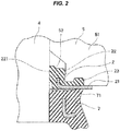
Fig. 2 is a partly enlarged view ofFig. 1 ; -
Fig. 3 is a plan view of a plate member which is used inFig. 1 ; -
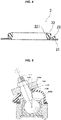
Fig. 4 is a cross-sectional view along a line A-A inFig. 3 ; -
Fig. 5 is a vertical cross-sectional view of a taper alignment ball joint according to the prior art; -
Fig. 6 is a top elevational view of a pinch bolt type ball joint according to the prior art; and -
Fig. 7 is a side elevational view ofFig. 6 . - A description will be given below of a mode for carrying out the present invention.
- As shown in
Figs. 1 ,2 ,3 and4 , adust cover 6 for a ball joint according to the present invention is structured such that a spherical head portion formed in one end of a ball stud 1 is retained within asocket 3, and ashaft 4 in the other end of the ball stud 1 is fixed to aknuckle 5 side by fastening theknuckle 5 by a fastening means 520 such as a bolt. - Further, the
dust cover 6 is structured such that a one end large-diameter opening portion 8 is fixed and retained to an outer peripheral surface of thesocket 3, and the other end small-diameter opening portion 7 is retained to theshaft 4. - Further, a basic structure is provided by that the
plate member 2 is retained between an inner peripheral surface of theknuckle 5 in the other end small-diameter opening portion 7 side and an outer peripheral surface of theshaft 4. - This kind of
knuckle 5 is used in the pinch bolt type ball joint, and is fastened and fixed onto the outer peripheral surface of theshaft 4 by the fastening means 520 such as the bolt, and anannular step portion 52 is formed in the inner peripheral surface of theknuckle 5 in the other end small-diameter opening portion 7 side (a lower surface side on the drawing). - Further, the
plate member 2 is constructed by anannular plate member 21 which is made of a hard material, anannular seal portion 22 which is integrally formed in an inner peripheral side of theannular plate member 21 and is made of a rubber-like elastic material, and anengagement projection 23 which is provided in a surface of theannular plate member 21 in theknuckle 5 side, engages with anotch portion 51 and is made of a rubber-like elastic material, and theannular seal portion 22 is retained in a compression manner between anannular step portion 52 which is provided in an inner peripheral surface of theknuckle 5 and an outer peripheral surface of theshaft 4. - As mentioned above, the
annular seal portion 22 is inserted between theannular step portion 52 provided in the inner peripheral surface of theknuckle 5 and the outer peripheral surface of theshaft 4, theknuckle 5 is thereafter fastened by the fastening means 520 such as the bolt, and a gap of thenotch portion 51 is reduced. As a result, since theannular seal portion 22 is compressed between theannular step portion 52 and the outer peripheral surface of theshaft 4, a good sealing state can be achieved. - Further, as shown in
Fig. 4 , since aseal lip portion 221 coming into contact with an outer peripheral surface of theshaft 4 is provided in an inner peripheral surface of theannular seal portion 22, it is possible to more securely achieve the seal between theannular seal portion 22 and the outer peripheral surface of theshaft 4. - In the same manner, since the
engagement projection 23 made of the rubber-like elastic material is inserted into the gap of thenotch portion 51, theknuckle 5 is thereafter fastened by the bolt means 520, and the gap of thenotch portion 51 is reduced, it is possible to maintain a state in which theengagement projection 23 is securely retained to thenotch portion 51. As a result, it is possible to securely prevent the corotation of theplate member 2 in relation to theknuckle 5, and a stable sealing performance can be maintained. - Further, since a
dust lip 71 coming into close contact with a lower surface of theannular plate member 21 is provided in the other end small-diameter opening portion 7, it is possible to obtain the same water prevention and dust prevention effects as those of the taper alignment ball joint, even in the pinch bolt type ball joint. - Further, a metal material and a resin material can be appropriately selected and employed as a material of the
annular plate member 21. - Further, a material of the
dust cover 6 employs by appropriately selecting from rubber-like elastic materials such as chloroprene, polyester elastomer and thermoplastic elastomer such as thermoplastic polyurethane in conformity to intended use. - Further, grease is sealed into the
dust cover 6. - On the other hand, a metal reinforcing ring is buried and integrated into the other end small-
diameter opening portion 7 and the one end large-diameter openingportion 8 of thedust cover 6. - Further, it goes without saying that the present invention is not limited to the best mode for carrying out the invention mentioned above, but can employ the other various structures without deviating from the scope of the present invention.
- The present invention can be used for the ball joint which is used in the suspension device, the steering device and so on of the motor vehicle.
-
- 1
- ball stud
- 2
- plate member
- 3
- socket
- 4
- shaft
- 5
- knuckle
- 6
- dust cover
- 7
- other end small-diameter opening portion
- 8
- one end large-diameter opening portion
- 21
- annular plate member
- 22
- annular seal portion
- 23
- engagement projection
- 51
- notch portion
- 52
- annular step portion
- 71
- dust lip
- 221
- seal lip portion
Claims (3)
- A dust cover (6) for a ball joint structured such that a spherical head portion formed in one end of a ball stud (1) is retained within a socket (3), a shaft (4) in the other end of said ball stud (1) is fixed to a knuckle (5) having a notch portion (51) by fastening said knuckle (5) by means of a fastening means (520), a one end large-diameter opening portion (8) is fixed and retained to an outer peripheral surface of said socket (3), the other end small-diameter opening portion (7) is retained to said shaft (4), and a plate member (2) is retained between an inner peripheral surface of said knuckle (5) in said other end small-diameter opening portion (7) side and an outer peripheral surface of said shaft (4),
wherein said plate member (2) is constructed by an annular plate member (21) which is made of a hard material, an annular seal portion (22) which is integrally formed in an inner peripheral side of said annular plate member (21) and is made of a rubber-like elastic material, and an engagement projection (23) which is provided in a surface of said annular plate member (21) in said knuckle (5) side, engages with said notch portion (51) and is made of a rubber-like elastic material (23), and said annular seal portion (22) is retained in a compression manner between an annular step portion (52) which is provided in an inner peripheral surface of said knuckle (5) and an outer peripheral surface of said shaft (4). - The dust cover for the ball joint according to claim 1, wherein a seal lip portion (221) coming into contact with the outer peripheral surface of said shaft (4) is formed in an inner peripheral surface of said annular seal portion (22).
- The dust cover for the ball joint according to claim 1 or 2, wherein a dust lip (71) provided in said other end small-diameter opening portion (7) comes into close contact with said annular plate member (21).
Applications Claiming Priority (2)
| Application Number | Priority Date | Filing Date | Title |
|---|---|---|---|
| JP2014024977A JP6195226B2 (en) | 2014-02-13 | 2014-02-13 | Dust cover for ball joint |
| PCT/JP2015/053205 WO2015122341A1 (en) | 2014-02-13 | 2015-02-05 | Dust cover for ball joint |
Publications (3)
| Publication Number | Publication Date |
|---|---|
| EP3106687A1 true EP3106687A1 (en) | 2016-12-21 |
| EP3106687A4 EP3106687A4 (en) | 2017-01-11 |
| EP3106687B1 EP3106687B1 (en) | 2018-01-03 |
Family
ID=53800088
Family Applications (1)
| Application Number | Title | Priority Date | Filing Date |
|---|---|---|---|
| EP15749547.4A Not-in-force EP3106687B1 (en) | 2014-02-13 | 2015-02-05 | Dust cover for ball joint |
Country Status (5)
| Country | Link |
|---|---|
| US (1) | US9850940B2 (en) |
| EP (1) | EP3106687B1 (en) |
| JP (1) | JP6195226B2 (en) |
| CN (1) | CN106233009B (en) |
| WO (1) | WO2015122341A1 (en) |
Families Citing this family (7)
| Publication number | Priority date | Publication date | Assignee | Title |
|---|---|---|---|---|
| JP6323561B2 (en) * | 2014-08-21 | 2018-05-16 | Nok株式会社 | Dust cover |
| WO2017018168A1 (en) * | 2015-07-27 | 2017-02-02 | Nok株式会社 | Ball joint dust cover |
| US20200277984A1 (en) * | 2015-11-20 | 2020-09-03 | Nok Corporation | Dust cover for ball joint and method of attaching the same |
| DE102016003781A1 (en) * | 2016-03-29 | 2017-10-05 | Liebherr-Mining Equipment Colmar Sas | Sealing device for sealing the ball joint of a kingpin |
| US11473615B2 (en) * | 2018-06-27 | 2022-10-18 | Synergy Manufacturing, Inc. | Ball joint assembly |
| US11713783B2 (en) * | 2021-07-23 | 2023-08-01 | Federal-Mogul Motorparts Llc | Grease boot for a ball joint |
| US20250230836A1 (en) * | 2022-02-24 | 2025-07-17 | Nok Corporation | Ball joint seal structure and ferrule ring mounting method |
Family Cites Families (19)
| Publication number | Priority date | Publication date | Assignee | Title |
|---|---|---|---|---|
| US1704740A (en) * | 1917-11-30 | 1929-03-12 | Packard Motor Car Co | Steering-rod connection |
| JPS58130118U (en) * | 1982-02-27 | 1983-09-02 | いすゞ自動車株式会社 | ball joint |
| JP2558795Y2 (en) * | 1991-10-28 | 1998-01-14 | 株式会社リズム | Ball joint dust cover mounting structure |
| JP3663849B2 (en) | 1997-08-21 | 2005-06-22 | Nok株式会社 | Dust cover |
| DE19910689C1 (en) * | 1999-03-10 | 2000-11-23 | Zf Lemfoerder Metallwaren Ag | Ball joint |
| US20040028302A1 (en) * | 1999-03-17 | 2004-02-12 | Zf Lemforder Metallwaren Ag | Ball-and-socket joint |
| DE10124295C5 (en) * | 2001-05-17 | 2008-09-04 | ZF Lemförder GmbH | ball joint |
| EP1460289B1 (en) * | 2001-12-25 | 2010-01-20 | Musashi Seimitsu Kogyo Kabushiki Kaisha | Structure for coupling ball joint and arm |
| JP3980902B2 (en) * | 2002-02-21 | 2007-09-26 | 武蔵精密工業株式会社 | Ball joint |
| DE102004001465B4 (en) * | 2004-01-08 | 2006-04-20 | Zf Friedrichshafen Ag | Ball joint, preferably for use in vehicles |
| JPWO2006077677A1 (en) * | 2005-01-21 | 2008-06-19 | Nok株式会社 | gasket |
| JP4873122B2 (en) * | 2005-11-21 | 2012-02-08 | Nok株式会社 | Dust cover |
| DE102006052254B4 (en) * | 2006-11-03 | 2012-12-20 | Zf Friedrichshafen Ag | ball joint |
| JP5900790B2 (en) * | 2011-11-07 | 2016-04-06 | Nok株式会社 | Dust cover for ball joint |
| JP2013130261A (en) * | 2011-12-22 | 2013-07-04 | Nok Corp | Dust cover for ball joint |
| JP2013228037A (en) * | 2012-04-25 | 2013-11-07 | Jtekt Corp | Ball joint |
| JP6067274B2 (en) * | 2012-08-09 | 2017-01-25 | Nok株式会社 | Dust cover for ball joint |
| JP6119965B2 (en) * | 2012-12-19 | 2017-04-26 | Nok株式会社 | Dust cover for ball joint |
| JP6150117B2 (en) * | 2013-06-25 | 2017-06-21 | Nok株式会社 | Dust cover for ball joint |
-
2014
- 2014-02-13 JP JP2014024977A patent/JP6195226B2/en active Active
-
2015
- 2015-02-05 EP EP15749547.4A patent/EP3106687B1/en not_active Not-in-force
- 2015-02-05 US US15/034,201 patent/US9850940B2/en not_active Expired - Fee Related
- 2015-02-05 WO PCT/JP2015/053205 patent/WO2015122341A1/en not_active Ceased
- 2015-02-05 CN CN201580008445.7A patent/CN106233009B/en not_active Expired - Fee Related
Also Published As
| Publication number | Publication date |
|---|---|
| EP3106687A4 (en) | 2017-01-11 |
| US9850940B2 (en) | 2017-12-26 |
| WO2015122341A1 (en) | 2015-08-20 |
| EP3106687B1 (en) | 2018-01-03 |
| US20160273578A1 (en) | 2016-09-22 |
| CN106233009B (en) | 2018-10-23 |
| JP2015152058A (en) | 2015-08-24 |
| JP6195226B2 (en) | 2017-09-13 |
| CN106233009A (en) | 2016-12-14 |
Similar Documents
| Publication | Publication Date | Title |
|---|---|---|
| EP3106687B1 (en) | Dust cover for ball joint | |
| US9206837B2 (en) | Ball joint dust cover | |
| US20170159701A1 (en) | Dust cover for ball joint | |
| EP2913543A1 (en) | Ball joint dust cover | |
| CN107850112A (en) | Ball pivot dust cover | |
| US9528547B2 (en) | Dust cover for ball joint | |
| US20160281771A1 (en) | Dust cover for ball joint | |
| CN108138835A (en) | Dust cover | |
| JP5057219B2 (en) | Dust cover for ball joint | |
| EP2778446A1 (en) | Dust cover for ball joint | |
| CN108291573B (en) | Dust cover for ball joint and installation method of dust cover for ball joint | |
| JP5533592B2 (en) | Dust cover for ball joint | |
| JP2013160327A (en) | Dust cover for ball joint | |
| EP2937581B1 (en) | Ball joint dust cover | |
| US20150176639A1 (en) | Dust cover for ball joint | |
| EP3686448B1 (en) | Ball joint | |
| JP6608582B2 (en) | Dust cover for ball joint |
Legal Events
| Date | Code | Title | Description |
|---|---|---|---|
| PUAI | Public reference made under article 153(3) epc to a published international application that has entered the european phase |
Free format text: ORIGINAL CODE: 0009012 |
|
| 17P | Request for examination filed |
Effective date: 20160510 |
|
| AK | Designated contracting states |
Kind code of ref document: A1 Designated state(s): AL AT BE BG CH CY CZ DE DK EE ES FI FR GB GR HR HU IE IS IT LI LT LU LV MC MK MT NL NO PL PT RO RS SE SI SK SM TR |
|
| AX | Request for extension of the european patent |
Extension state: BA ME |
|
| A4 | Supplementary search report drawn up and despatched |
Effective date: 20161214 |
|
| RIC1 | Information provided on ipc code assigned before grant |
Ipc: F16C 11/06 20060101AFI20161208BHEP Ipc: F16J 3/04 20060101ALI20161208BHEP Ipc: F16J 15/52 20060101ALI20161208BHEP |
|
| DAX | Request for extension of the european patent (deleted) | ||
| GRAP | Despatch of communication of intention to grant a patent |
Free format text: ORIGINAL CODE: EPIDOSNIGR1 |
|
| INTG | Intention to grant announced |
Effective date: 20170828 |
|
| GRAS | Grant fee paid |
Free format text: ORIGINAL CODE: EPIDOSNIGR3 |
|
| GRAA | (expected) grant |
Free format text: ORIGINAL CODE: 0009210 |
|
| AK | Designated contracting states |
Kind code of ref document: B1 Designated state(s): AL AT BE BG CH CY CZ DE DK EE ES FI FR GB GR HR HU IE IS IT LI LT LU LV MC MK MT NL NO PL PT RO RS SE SI SK SM TR |
|
| REG | Reference to a national code |
Ref country code: GB Ref legal event code: FG4D |
|
| REG | Reference to a national code |
Ref country code: CH Ref legal event code: EP Ref country code: AT Ref legal event code: REF Ref document number: 960562 Country of ref document: AT Kind code of ref document: T Effective date: 20180115 |
|
| REG | Reference to a national code |
Ref country code: IE Ref legal event code: FG4D |
|
| REG | Reference to a national code |
Ref country code: DE Ref legal event code: R096 Ref document number: 602015007240 Country of ref document: DE |
|
| REG | Reference to a national code |
Ref country code: FR Ref legal event code: PLFP Year of fee payment: 4 |
|
| REG | Reference to a national code |
Ref country code: NL Ref legal event code: MP Effective date: 20180103 |
|
| REG | Reference to a national code |
Ref country code: LT Ref legal event code: MG4D |
|
| REG | Reference to a national code |
Ref country code: AT Ref legal event code: MK05 Ref document number: 960562 Country of ref document: AT Kind code of ref document: T Effective date: 20180103 |
|
| PG25 | Lapsed in a contracting state [announced via postgrant information from national office to epo] |
Ref country code: NL Free format text: LAPSE BECAUSE OF FAILURE TO SUBMIT A TRANSLATION OF THE DESCRIPTION OR TO PAY THE FEE WITHIN THE PRESCRIBED TIME-LIMIT Effective date: 20180103 |
|
| PG25 | Lapsed in a contracting state [announced via postgrant information from national office to epo] |
Ref country code: ES Free format text: LAPSE BECAUSE OF FAILURE TO SUBMIT A TRANSLATION OF THE DESCRIPTION OR TO PAY THE FEE WITHIN THE PRESCRIBED TIME-LIMIT Effective date: 20180103 Ref country code: LT Free format text: LAPSE BECAUSE OF FAILURE TO SUBMIT A TRANSLATION OF THE DESCRIPTION OR TO PAY THE FEE WITHIN THE PRESCRIBED TIME-LIMIT Effective date: 20180103 Ref country code: CY Free format text: LAPSE BECAUSE OF FAILURE TO SUBMIT A TRANSLATION OF THE DESCRIPTION OR TO PAY THE FEE WITHIN THE PRESCRIBED TIME-LIMIT Effective date: 20180103 Ref country code: FI Free format text: LAPSE BECAUSE OF FAILURE TO SUBMIT A TRANSLATION OF THE DESCRIPTION OR TO PAY THE FEE WITHIN THE PRESCRIBED TIME-LIMIT Effective date: 20180103 Ref country code: NO Free format text: LAPSE BECAUSE OF FAILURE TO SUBMIT A TRANSLATION OF THE DESCRIPTION OR TO PAY THE FEE WITHIN THE PRESCRIBED TIME-LIMIT Effective date: 20180403 Ref country code: HR Free format text: LAPSE BECAUSE OF FAILURE TO SUBMIT A TRANSLATION OF THE DESCRIPTION OR TO PAY THE FEE WITHIN THE PRESCRIBED TIME-LIMIT Effective date: 20180103 |
|
| PG25 | Lapsed in a contracting state [announced via postgrant information from national office to epo] |
Ref country code: LV Free format text: LAPSE BECAUSE OF FAILURE TO SUBMIT A TRANSLATION OF THE DESCRIPTION OR TO PAY THE FEE WITHIN THE PRESCRIBED TIME-LIMIT Effective date: 20180103 Ref country code: SE Free format text: LAPSE BECAUSE OF FAILURE TO SUBMIT A TRANSLATION OF THE DESCRIPTION OR TO PAY THE FEE WITHIN THE PRESCRIBED TIME-LIMIT Effective date: 20180103 Ref country code: RS Free format text: LAPSE BECAUSE OF FAILURE TO SUBMIT A TRANSLATION OF THE DESCRIPTION OR TO PAY THE FEE WITHIN THE PRESCRIBED TIME-LIMIT Effective date: 20180103 Ref country code: AT Free format text: LAPSE BECAUSE OF FAILURE TO SUBMIT A TRANSLATION OF THE DESCRIPTION OR TO PAY THE FEE WITHIN THE PRESCRIBED TIME-LIMIT Effective date: 20180103 Ref country code: BG Free format text: LAPSE BECAUSE OF FAILURE TO SUBMIT A TRANSLATION OF THE DESCRIPTION OR TO PAY THE FEE WITHIN THE PRESCRIBED TIME-LIMIT Effective date: 20180403 Ref country code: IS Free format text: LAPSE BECAUSE OF FAILURE TO SUBMIT A TRANSLATION OF THE DESCRIPTION OR TO PAY THE FEE WITHIN THE PRESCRIBED TIME-LIMIT Effective date: 20180503 Ref country code: PL Free format text: LAPSE BECAUSE OF FAILURE TO SUBMIT A TRANSLATION OF THE DESCRIPTION OR TO PAY THE FEE WITHIN THE PRESCRIBED TIME-LIMIT Effective date: 20180103 Ref country code: GR Free format text: LAPSE BECAUSE OF FAILURE TO SUBMIT A TRANSLATION OF THE DESCRIPTION OR TO PAY THE FEE WITHIN THE PRESCRIBED TIME-LIMIT Effective date: 20180404 |
|
| REG | Reference to a national code |
Ref country code: CH Ref legal event code: PL |
|
| REG | Reference to a national code |
Ref country code: DE Ref legal event code: R097 Ref document number: 602015007240 Country of ref document: DE |
|
| PG25 | Lapsed in a contracting state [announced via postgrant information from national office to epo] |
Ref country code: AL Free format text: LAPSE BECAUSE OF FAILURE TO SUBMIT A TRANSLATION OF THE DESCRIPTION OR TO PAY THE FEE WITHIN THE PRESCRIBED TIME-LIMIT Effective date: 20180103 Ref country code: MC Free format text: LAPSE BECAUSE OF FAILURE TO SUBMIT A TRANSLATION OF THE DESCRIPTION OR TO PAY THE FEE WITHIN THE PRESCRIBED TIME-LIMIT Effective date: 20180103 Ref country code: RO Free format text: LAPSE BECAUSE OF FAILURE TO SUBMIT A TRANSLATION OF THE DESCRIPTION OR TO PAY THE FEE WITHIN THE PRESCRIBED TIME-LIMIT Effective date: 20180103 Ref country code: EE Free format text: LAPSE BECAUSE OF FAILURE TO SUBMIT A TRANSLATION OF THE DESCRIPTION OR TO PAY THE FEE WITHIN THE PRESCRIBED TIME-LIMIT Effective date: 20180103 Ref country code: IT Free format text: LAPSE BECAUSE OF FAILURE TO SUBMIT A TRANSLATION OF THE DESCRIPTION OR TO PAY THE FEE WITHIN THE PRESCRIBED TIME-LIMIT Effective date: 20180103 |
|
| PLBE | No opposition filed within time limit |
Free format text: ORIGINAL CODE: 0009261 |
|
| STAA | Information on the status of an ep patent application or granted ep patent |
Free format text: STATUS: NO OPPOSITION FILED WITHIN TIME LIMIT |
|
| REG | Reference to a national code |
Ref country code: IE Ref legal event code: MM4A |
|
| REG | Reference to a national code |
Ref country code: BE Ref legal event code: MM Effective date: 20180228 |
|
| PG25 | Lapsed in a contracting state [announced via postgrant information from national office to epo] |
Ref country code: LU Free format text: LAPSE BECAUSE OF NON-PAYMENT OF DUE FEES Effective date: 20180205 Ref country code: SM Free format text: LAPSE BECAUSE OF FAILURE TO SUBMIT A TRANSLATION OF THE DESCRIPTION OR TO PAY THE FEE WITHIN THE PRESCRIBED TIME-LIMIT Effective date: 20180103 Ref country code: SK Free format text: LAPSE BECAUSE OF FAILURE TO SUBMIT A TRANSLATION OF THE DESCRIPTION OR TO PAY THE FEE WITHIN THE PRESCRIBED TIME-LIMIT Effective date: 20180103 Ref country code: DK Free format text: LAPSE BECAUSE OF FAILURE TO SUBMIT A TRANSLATION OF THE DESCRIPTION OR TO PAY THE FEE WITHIN THE PRESCRIBED TIME-LIMIT Effective date: 20180103 Ref country code: CH Free format text: LAPSE BECAUSE OF NON-PAYMENT OF DUE FEES Effective date: 20180228 Ref country code: CZ Free format text: LAPSE BECAUSE OF FAILURE TO SUBMIT A TRANSLATION OF THE DESCRIPTION OR TO PAY THE FEE WITHIN THE PRESCRIBED TIME-LIMIT Effective date: 20180103 Ref country code: LI Free format text: LAPSE BECAUSE OF NON-PAYMENT OF DUE FEES Effective date: 20180228 |
|
| 26N | No opposition filed |
Effective date: 20181005 |
|
| PG25 | Lapsed in a contracting state [announced via postgrant information from national office to epo] |
Ref country code: IE Free format text: LAPSE BECAUSE OF NON-PAYMENT OF DUE FEES Effective date: 20180205 |
|
| PG25 | Lapsed in a contracting state [announced via postgrant information from national office to epo] |
Ref country code: BE Free format text: LAPSE BECAUSE OF NON-PAYMENT OF DUE FEES Effective date: 20180228 Ref country code: SI Free format text: LAPSE BECAUSE OF FAILURE TO SUBMIT A TRANSLATION OF THE DESCRIPTION OR TO PAY THE FEE WITHIN THE PRESCRIBED TIME-LIMIT Effective date: 20180103 |
|
| PG25 | Lapsed in a contracting state [announced via postgrant information from national office to epo] |
Ref country code: MT Free format text: LAPSE BECAUSE OF NON-PAYMENT OF DUE FEES Effective date: 20180205 |
|
| PG25 | Lapsed in a contracting state [announced via postgrant information from national office to epo] |
Ref country code: TR Free format text: LAPSE BECAUSE OF FAILURE TO SUBMIT A TRANSLATION OF THE DESCRIPTION OR TO PAY THE FEE WITHIN THE PRESCRIBED TIME-LIMIT Effective date: 20180103 |
|
| PGFP | Annual fee paid to national office [announced via postgrant information from national office to epo] |
Ref country code: DE Payment date: 20200121 Year of fee payment: 6 Ref country code: GB Payment date: 20200129 Year of fee payment: 6 |
|
| PG25 | Lapsed in a contracting state [announced via postgrant information from national office to epo] |
Ref country code: PT Free format text: LAPSE BECAUSE OF FAILURE TO SUBMIT A TRANSLATION OF THE DESCRIPTION OR TO PAY THE FEE WITHIN THE PRESCRIBED TIME-LIMIT Effective date: 20180103 |
|
| PG25 | Lapsed in a contracting state [announced via postgrant information from national office to epo] |
Ref country code: HU Free format text: LAPSE BECAUSE OF FAILURE TO SUBMIT A TRANSLATION OF THE DESCRIPTION OR TO PAY THE FEE WITHIN THE PRESCRIBED TIME-LIMIT; INVALID AB INITIO Effective date: 20150205 Ref country code: MK Free format text: LAPSE BECAUSE OF NON-PAYMENT OF DUE FEES Effective date: 20180103 |
|
| PGFP | Annual fee paid to national office [announced via postgrant information from national office to epo] |
Ref country code: FR Payment date: 20200113 Year of fee payment: 6 |
|
| REG | Reference to a national code |
Ref country code: DE Ref legal event code: R119 Ref document number: 602015007240 Country of ref document: DE |
|
| GBPC | Gb: european patent ceased through non-payment of renewal fee |
Effective date: 20210205 |
|
| PG25 | Lapsed in a contracting state [announced via postgrant information from national office to epo] |
Ref country code: GB Free format text: LAPSE BECAUSE OF NON-PAYMENT OF DUE FEES Effective date: 20210205 Ref country code: FR Free format text: LAPSE BECAUSE OF NON-PAYMENT OF DUE FEES Effective date: 20210228 Ref country code: DE Free format text: LAPSE BECAUSE OF NON-PAYMENT OF DUE FEES Effective date: 20210901 |