EP3106672A1 - Carter à injecteurs de vortex pour compresseur de turbomachine axiale - Google Patents
Carter à injecteurs de vortex pour compresseur de turbomachine axiale Download PDFInfo
- Publication number
- EP3106672A1 EP3106672A1 EP16174588.0A EP16174588A EP3106672A1 EP 3106672 A1 EP3106672 A1 EP 3106672A1 EP 16174588 A EP16174588 A EP 16174588A EP 3106672 A1 EP3106672 A1 EP 3106672A1
- Authority
- EP
- European Patent Office
- Prior art keywords
- rotor
- vortex
- injection
- turbomachine
- vortices
- Prior art date
- Legal status (The legal status is an assumption and is not a legal conclusion. Google has not performed a legal analysis and makes no representation as to the accuracy of the status listed.)
- Granted
Links
Images


Classifications
-
- F—MECHANICAL ENGINEERING; LIGHTING; HEATING; WEAPONS; BLASTING
- F04—POSITIVE - DISPLACEMENT MACHINES FOR LIQUIDS; PUMPS FOR LIQUIDS OR ELASTIC FLUIDS
- F04D—NON-POSITIVE-DISPLACEMENT PUMPS
- F04D29/00—Details, component parts, or accessories
- F04D29/66—Combating cavitation, whirls, noise, vibration or the like; Balancing
- F04D29/661—Combating cavitation, whirls, noise, vibration or the like; Balancing especially adapted for elastic fluid pumps
-
- F—MECHANICAL ENGINEERING; LIGHTING; HEATING; WEAPONS; BLASTING
- F04—POSITIVE - DISPLACEMENT MACHINES FOR LIQUIDS; PUMPS FOR LIQUIDS OR ELASTIC FLUIDS
- F04D—NON-POSITIVE-DISPLACEMENT PUMPS
- F04D29/00—Details, component parts, or accessories
- F04D29/66—Combating cavitation, whirls, noise, vibration or the like; Balancing
- F04D29/68—Combating cavitation, whirls, noise, vibration or the like; Balancing by influencing boundary layers
- F04D29/681—Combating cavitation, whirls, noise, vibration or the like; Balancing by influencing boundary layers especially adapted for elastic fluid pumps
- F04D29/685—Inducing localised fluid recirculation in the stator-rotor interface
-
- F—MECHANICAL ENGINEERING; LIGHTING; HEATING; WEAPONS; BLASTING
- F01—MACHINES OR ENGINES IN GENERAL; ENGINE PLANTS IN GENERAL; STEAM ENGINES
- F01D—NON-POSITIVE DISPLACEMENT MACHINES OR ENGINES, e.g. STEAM TURBINES
- F01D11/00—Preventing or minimising internal leakage of working-fluid, e.g. between stages
- F01D11/02—Preventing or minimising internal leakage of working-fluid, e.g. between stages by non-contact sealings, e.g. of labyrinth type
- F01D11/04—Preventing or minimising internal leakage of working-fluid, e.g. between stages by non-contact sealings, e.g. of labyrinth type using sealing fluid, e.g. steam
-
- F—MECHANICAL ENGINEERING; LIGHTING; HEATING; WEAPONS; BLASTING
- F01—MACHINES OR ENGINES IN GENERAL; ENGINE PLANTS IN GENERAL; STEAM ENGINES
- F01D—NON-POSITIVE DISPLACEMENT MACHINES OR ENGINES, e.g. STEAM TURBINES
- F01D11/00—Preventing or minimising internal leakage of working-fluid, e.g. between stages
- F01D11/08—Preventing or minimising internal leakage of working-fluid, e.g. between stages for sealing space between rotor blade tips and stator
- F01D11/14—Adjusting or regulating tip-clearance, i.e. distance between rotor-blade tips and stator casing
-
- F—MECHANICAL ENGINEERING; LIGHTING; HEATING; WEAPONS; BLASTING
- F04—POSITIVE - DISPLACEMENT MACHINES FOR LIQUIDS; PUMPS FOR LIQUIDS OR ELASTIC FLUIDS
- F04D—NON-POSITIVE-DISPLACEMENT PUMPS
- F04D27/00—Control, e.g. regulation, of pumps, pumping installations or pumping systems specially adapted for elastic fluids
- F04D27/02—Surge control
-
- F—MECHANICAL ENGINEERING; LIGHTING; HEATING; WEAPONS; BLASTING
- F04—POSITIVE - DISPLACEMENT MACHINES FOR LIQUIDS; PUMPS FOR LIQUIDS OR ELASTIC FLUIDS
- F04D—NON-POSITIVE-DISPLACEMENT PUMPS
- F04D27/00—Control, e.g. regulation, of pumps, pumping installations or pumping systems specially adapted for elastic fluids
- F04D27/02—Surge control
- F04D27/0207—Surge control by bleeding, bypassing or recycling fluids
- F04D27/0215—Arrangements therefor, e.g. bleed or by-pass valves
-
- F—MECHANICAL ENGINEERING; LIGHTING; HEATING; WEAPONS; BLASTING
- F04—POSITIVE - DISPLACEMENT MACHINES FOR LIQUIDS; PUMPS FOR LIQUIDS OR ELASTIC FLUIDS
- F04D—NON-POSITIVE-DISPLACEMENT PUMPS
- F04D27/00—Control, e.g. regulation, of pumps, pumping installations or pumping systems specially adapted for elastic fluids
- F04D27/02—Surge control
- F04D27/0207—Surge control by bleeding, bypassing or recycling fluids
- F04D27/0238—Details or means for fluid reinjection
-
- F—MECHANICAL ENGINEERING; LIGHTING; HEATING; WEAPONS; BLASTING
- F04—POSITIVE - DISPLACEMENT MACHINES FOR LIQUIDS; PUMPS FOR LIQUIDS OR ELASTIC FLUIDS
- F04D—NON-POSITIVE-DISPLACEMENT PUMPS
- F04D29/00—Details, component parts, or accessories
- F04D29/40—Casings; Connections of working fluid
- F04D29/52—Casings; Connections of working fluid for axial pumps
- F04D29/522—Casings; Connections of working fluid for axial pumps especially adapted for elastic fluid pumps
- F04D29/526—Details of the casing section radially opposing blade tips
-
- F—MECHANICAL ENGINEERING; LIGHTING; HEATING; WEAPONS; BLASTING
- F01—MACHINES OR ENGINES IN GENERAL; ENGINE PLANTS IN GENERAL; STEAM ENGINES
- F01D—NON-POSITIVE DISPLACEMENT MACHINES OR ENGINES, e.g. STEAM TURBINES
- F01D11/00—Preventing or minimising internal leakage of working-fluid, e.g. between stages
- F01D11/08—Preventing or minimising internal leakage of working-fluid, e.g. between stages for sealing space between rotor blade tips and stator
- F01D11/10—Preventing or minimising internal leakage of working-fluid, e.g. between stages for sealing space between rotor blade tips and stator using sealing fluid, e.g. steam
-
- F—MECHANICAL ENGINEERING; LIGHTING; HEATING; WEAPONS; BLASTING
- F05—INDEXING SCHEMES RELATING TO ENGINES OR PUMPS IN VARIOUS SUBCLASSES OF CLASSES F01-F04
- F05D—INDEXING SCHEME FOR ASPECTS RELATING TO NON-POSITIVE-DISPLACEMENT MACHINES OR ENGINES, GAS-TURBINES OR JET-PROPULSION PLANTS
- F05D2220/00—Application
- F05D2220/30—Application in turbines
- F05D2220/32—Application in turbines in gas turbines
-
- F—MECHANICAL ENGINEERING; LIGHTING; HEATING; WEAPONS; BLASTING
- F05—INDEXING SCHEMES RELATING TO ENGINES OR PUMPS IN VARIOUS SUBCLASSES OF CLASSES F01-F04
- F05D—INDEXING SCHEME FOR ASPECTS RELATING TO NON-POSITIVE-DISPLACEMENT MACHINES OR ENGINES, GAS-TURBINES OR JET-PROPULSION PLANTS
- F05D2240/00—Components
- F05D2240/55—Seals
Definitions
- the invention relates to leakage vortices in turbomachine rotor blade heads. More precisely, the invention deals with a casing for limiting the effect of vortices in blade heads which limit the stability of an axial turbomachine compressor.
- the invention also proposes a compressor, and an aircraft turbojet engine.
- An axial turbomachine compressor has alternating rows of rotor vanes and rows of stator vanes.
- the rotation of the rotor and its blades contributes to gradually compressing the primary flow through the turbomachine.
- this compression is accompanied by leaks between the rotor blade heads and the housing that surrounds them. Indeed, a mechanical game is necessary at this interface to avoid contacts.
- the blade heads sweep the inner surface of the housing and the leaks bypass the blade heads forming vortices to the intrados.
- Each vortex delimits a blocking zone against its blade where the fluid has a small amount of movement.
- the vortex may gain the leading edge of the next dawn. Therefore, the flow in the blocking zone can be reversed and the compressor can become unstable. A pumping phenomenon can occur, a crankcase treatment avoids it.
- the document US2011 / 0299979A1 discloses a turbomachine with a compressor.
- the compressor has a fixed stator and a movable wheel supporting annular rows of blades.
- the stator comprises an outer casing surrounding the rotor blades, said casing having annular grooves at the blades. These grooves have varying depths to preserve the stall margin of the compressor. However, the depth and width of each groove increases bladehead leakage, limiting the compression ratio of the compressor. In addition, the performance of the turbomachine is degraded.
- the document EP2778427A2 discloses a compressor for a turbomachine, comprising a system for recirculating sucked air.
- the system comprises a plurality of suction ports extending through a collector.
- An annular suction cavity surrounds the manifold and is in communication with outlet openings of the suction ports.
- the suction ports allow communication between the main gas flow passage and the annular cavity.
- the annular cavity includes exit passages with orifices disposed in the manifold.
- the air is passively drawn through the suction holes, circulates through the annular cavity and is fed back into the main gas flow passage in a second axial position.
- the effectiveness of this system to stem leaks at the head of dawn remains limited.
- the quantity of air taken off significantly penalizes the efficiency of the turbomachine.
- the object of the invention is to solve at least one of the problems posed by the prior art. More precisely, the purpose of the invention is to increase the efficiency of a turbomachine. The invention also aims to push the limit to the stall of a compressor of an axial turbomachine.
- the invention relates to an assembly for an axial turbomachine, in particular for an axial turbomachine compressor, the assembly comprising: a rotor with at least one annular row of rotor blades, a stator casing surrounding the row of rotor blades, and set being configured so that during operation of the turbomachine, the movement of the vanes creates leakage vortices between the housing and the blades; remarkable in that the casing comprises a vortex generator device at the level of the leakage vortices, the device being configured so that in operation the vortex vortex rotate in the opposite direction of the leakage vortices they encounter in order to to counter them.
- each counter-vortex generating device is configured so that, in operation, the vortexes have rotation axes that are mainly parallel to the leakage vortices, each vortex generating device being preferably implanted on the housing.
- the vortex generating device comprises orifice injection modules, preferably the casing comprises a plurality of injection modules angularly distributed around the rotor.
- At least one or each injection module comprises at least one injection orifice arranged upstream of the row of rotor blades.
- At least one or each injection orifice comprises internal fins configured to generate a vortex from a flow passing through said orifice, optionally at least one or more modules comprise a plurality of orifices. injection with internal fins configured to generate vortexes.
- At least one or each injection module comprises a set of injection orifices inclined with respect to each other so as to form a vortex from a flow coming from said injection ports of the game
- At least one or each injection module comprises at least one upstream injection orifice and one downstream injection orifice which are offset axially and / or circumferentially of the casing; said orifices being inclined relative to each other along an axial plane and / or with respect to a plane perpendicular to the axis of rotation of the rotor.
- At least one or each injection module comprises means for taking air, in particular an air sampling orifice, possibly disposed downstream of the row of blades.
- At least one or each injection module comprises a pair of channels each connecting an injection orifice upstream of the blades to a sampling orifice downstream of the blades, preferably the channels of each pair. cross.
- the housing comprises a main internal surface surrounding the blades, at least one or more or each orifices flush with said inner surface.
- the blades comprise leading edges with external ends, the injection orifices being upstream of the outer ends of the leading edges.
- the vortex generating device comprises at least one or more channels axially passing through the at least one row of rotor blades.
- the counter-vortex generating device comprises a block made of material in which at least one or more channels are formed, preferably the block of material extends over the entire axial length of the at least one an annular row of rotor blades.
- the vortex generating device comprises a collector surrounding the housing, preferably the collector surrounds a space in which the row of blades is inscribed.
- the assembly comprises control means for generating alternately vortexes at a frequency which is a function of the speed of rotation of the rotor, the triggering of the generation of a counter-vortex. vortex possibly depending on the proximity of a blade with respect to a generating device.
- a radial clearance separates the outer ends of the blades of the housing, said clearance possibly surrounding the row of blades, and / or the clearance is an annular clearance.
- the casing comprises an annular seal, in particular an annular layer of abradable material, the vortex generating device extending upstream downstream from said annular seal and / or surrounding said annular seal.
- At least one or each injection module comprises at least one channel connecting an injection orifice to a sampling orifice.
- the set comprises several generating devices whose counter vortex rotate in the same direction.
- At least one or each injection orifice and / or at least one or each sampling orifice forms a passage oriented mainly radially.
- the main internal surface is the one having the largest extent.
- the collector is a distributor supplying pressurized air to each vortex generating device.
- the housing has an inner surface with a generally straight or substantially arcuate profile of revolution, said profile extending axially all along a row of rotor blades.
- leakage vortices and vortexes flow downstream.
- the leakage vortices turn helically, the device being configured so that in operation the vortex rotates helically in the opposite direction to the helical rotation direction of the leak vortices.
- the invention also relates to a turbomachine comprising an assembly, remarkable in that the assembly is in accordance with the invention; preferably, the rotor comprises several annular rows of vanes and the assembly comprises a plurality of counter vortex generating devices.
- the invention also relates to a method for controlling the stability of a turbomachine compressor, in particular a low pressure compressor, the compressor comprising: a rotor with at least one annular row of rotor blades, a housing enclosing the row of rotor blades, during the operation of the turbomachine, the displacement of the blades creates leakage vortices between the housing and the blades; remarkable in that the method comprises the generation of vortex vortex leak and rotating in the opposite direction of the vortex leak to limit, the turbomachine being optionally in accordance with the invention.
- the generated vortexes are generated in a discontinuous manner, in particular when approaching a leakage vortex.
- the vortexes generated are injected downstream, in particular towards leakage vortices.
- the outer ends of the blades have cords inclined relative to the axis of rotation of the rotor, during their generation the vortexes having helical winding axes generally parallel to the inclined cords. outer ends of blades.
- the assembly is configured for a transonic flow generating a shock at the blades.
- each object of the invention is also applicable to the other objects of the invention.
- each object of the invention is combinable with other objects.
- the invention makes it possible to confine leakage vortices, and possibly to reduce them. Their action is reduced both in terms of space and duration, so that their propagation towards the next dawn is dammed. From then on, each vortex of flight is folded against its reference dawn. The blocking zone is reduced, and is pushed back from the next rotor blade. The stability margin is then increased, and the yield is preserved.
- the invention makes it possible to maintain a homogeneous clearance between the blade and the casing, which improves the compression ratio of each compression stage.
- the inner surface of the housing also becomes simpler to achieve since it remains straight, and / or smooth.
- An embodiment of woven preform composite material remains simple.
- the use of channels between the orifices makes it possible to form loss of charges, possibly dynamic. By this means, it is possible to control the flow reinjected by the orifices as a function of the upstream-downstream pressure difference of the blades.
- the vortex generating device can then be adapted to promote the generation of vortex at a predefined regime, and to limit these vortices to another regime. It then becomes easier to design a turbomachine optimized for a nominal speed, while having a self-regulating or passive system.
- inner or inner and outer or outer refer to a positioning relative to the axis of rotation of an axial turbomachine.
- the axial direction corresponds to the direction along the axis of rotation of the turbomachine.
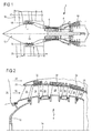
- the figure 1 represents in simplified manner an axial turbomachine. It is in this case a double-flow turbojet engine.
- the turbojet engine 2 comprises a first compression level, called a low-pressure compressor 4, a second compression level, called a high-pressure compressor 6, a combustion chamber 8 and one or more levels of turbines 10.
- a first compression level called a low-pressure compressor 4
- a second compression level called a high-pressure compressor 6
- a combustion chamber 8 and one or more levels of turbines 10.
- the mechanical power of the turbine 10 transmitted via the central shaft to the rotor 12 sets in motion the two compressors 4 and 6.
- the latter comprise several rows of rotor blades associated with rows of stator vanes.
- the rotation of the rotor about its axis of rotation 14 thus makes it possible to generate an air flow and to compress it gradually until it reaches the combustion chamber inlet 8. Reducing means can increase the speed of rotation transmitted. compressors.
- An inlet fan commonly referred to as fan or blower 16 is coupled to the rotor 12 and generates a flow of air which splits into a primary flow 18 passing through the above mentioned levels of the turbomachine, and a secondary flow 20 passing through an annular duct. (partially shown) along the machine to then join the primary flow at the turbine outlet.
- the secondary flow can be accelerated to generate a thrust reaction.
- the primary 18 and secondary 20 streams are annular flows, they are channeled by the casing of the turbomachine.
- the casing has cylindrical walls or ferrules which can be internal and external.
- the figure 2 is a sectional view of a compressor of an axial turbomachine such as that of the figure 1 .
- the compressor may be a low-pressure compressor 4.
- the rotor 12 comprises several rows of rotor blades 24, 1 occurrence three.
- the low pressure compressor 4 comprises several rectifiers, in this case four, which each contain a row of stator vanes 26.
- the rectifiers are associated with the fan 16 or with a row of rotor vanes to straighten the flow of air, so as to convert the speed of the flow into static pressure.
- the blades stator 26 extend substantially radially from an outer casing 28, and can be fixed and immobilized by means of axes. They are regularly spaced from each other, and have the same angular orientation in the flow. Seals 30, for example abradable, may cover the casing 28 at the level of the rotor vanes 24.
- the outer casing 28 is provided with counter-vortex generating devices 32, each associated with a row of rotor blades 24.
- Each vortex is a vortex.
- one or only certain rows of rotor blades 24 are provided with generating devices 32.
- the figure 3 sketch a plan view of a compressor section.
- the compressor can match that of the figure 2 .
- a rotor blade 24 is axially spaced from an injection port 34.
- a leakage vortex 36 propagates from the rotor blade head.
- the device 32 has a vortex injection orifice 34.
- This vortex 38 rotates in the opposite direction to the direction of rotation of the vortex leak 36 of the blade. When they meet, the leakage vortex 36 is reduced and its effect is countered.
- the injection orifice 34 may comprise fins 40.
- the fins 40 may be helical and angularly distributed inside the orifice 34. Their pitch, their spacings, their heights and their lengths make it possible to confer a rotational component on the interior of the orifice 34. a flow passing through the orifice.
- a vortex just like a vortex is understood as a spiral flow with a winding axis, possibly forming several successive and coherent turns.
- the air passing through the injection orifice 34 can be taken downstream in the compressor. It can also be from any other place of the turbomachine. Means may allow discontinuous feeding, for example to allow injection of a vortex to a vortex leak.
- the invention provides a method for combating leakage vortices by opposing vortex 38 which are injected locally and periodically.
- the figure 4 sketch a generator device 132 against vortex 138 according to a second embodiment of the invention. This figure 4 resumes the numbering of the preceding figures for identical or similar elements, however, the numbering is incremented by 100. Specific numbers are used for the specific elements of this embodiment.
- the axis of rotation 114 is shown as a marker.
- Generator device 132 includes a pressurized air manifold 142 and ports for drawing and injecting pressurized air.
- Collector 142 may form an annular cavity surrounding the rotor blade array 124 and convey air from downstream to upstream.
- the collector 142 may be delimited by the casing 128, possibly in the form of an outer shell, and / or an outer shell 144 attached to the casing 128.
- the collector 142 and / or the shell 144 may extend axially all the way through. along the blade bank 124, extending from the leading edge to the trailing edge.
- the injection ports may be grouped into sets of at least two ports to form a vortex. They can then form an injection module.
- the generator device 132 has several injection orifices, including an upstream injection orifice 134 and a downstream injection orifice 146. They are in communication with the sampling orifice 148 via the manifold 142. During the passage of a At the vane 124 at the sampling port 148, the pressure increase causes a flow through the manifold 142. This flow enters through the sampling port 148 and out through the injection ports (134; 146). The pressure in the manifold 142 can therefore be oscillating because of the repeated passage of the blades 124.
- the device 132 can be passive in the sense that it does not require external energy input.
- the simple passage of a blade 124 is enough to make it operational thanks to the variation of pressure. Reliability and energy saving are optimized.
- FIG 5 sketching a plan view of a portion of the compressor according to the second embodiment of the invention.
- An assembly with a rotor portion and a housing portion represented by orifices (134; 146) is illustrated.
- the axis of rotation 114 is shown as a marker.
- the upstream injection port 134 and the downstream injection port 146 may overlap axially and / or circumferentially. They can have rectangular shapes. Their offset, the inclinations of their respective output directions favor the birth of a vortex 138. For example, the injected flows are wound on one another, possibly in combination with the primary flow.
- the figure 6 is an axial section of the housing 128.
- the section is made along the axis of rotation 114.
- the orifices (134; 146) may correspond to those drawn on the figure 5 .
- the injection ports (134; 146) are formed in the thickness of the housing wall 128 radially therethrough. They may be inclined relative to each other, and / or inclined relative to perpendicular lines 149 to the axis of rotation 114 at different angles. By inclination of an orifice, it is possible to consider the direction of the flow which passes through it, and / or the direction of its median axis 150.
- the upstream orifice 134 may be inclined with respect to a perpendicular 149 to the axis of rotation 114. an angle ⁇ 1 between 30 ° and 50 °.
- the downstream orifice 146 may be inclined in the same direction, but at a lower angle; for example an angle ⁇ 2 between 25 ° and 45 °
- the figure 7 is a cross section of the housing 128 at a generator device 132.
- the cross section is in a plane perpendicular to the axis of rotation.
- the orifices (134; 146) may correspond to those drawn on the figure 5 and / or figure 6 .
- the injection ports (134; 146) are inclined without the perpendicular plane. They may be inclined relative to each other, and / or inclined relative to a perpendicular 149 to the axis of rotation 114 at different angles.
- the upstream orifice 134 is inclined with respect to a perpendicular 149 of an angle ⁇ 1 between 25 ° and 50 ° in the direction opposite to the direction of rotation.
- the downstream orifice 146 is inclined relative to a perpendicular 149 of an angle ⁇ 2 between 25 ° and 50 ° in the direction of rotation of the rotor.
- the figure 8 sketch a generator device section 232 according to a third embodiment of the invention. This figure 8 resumes the numbering of the preceding figures for the identical or similar elements, however the numbering is incremented by 200. Specific numbers are used for the elements specific to this embodiment.
- the axis of rotation 214 is shown as a marker.
- Generator device 232 may generally be similar to that of the second embodiment of the invention. It further comprises a block of material 252 attached to the collector 242, or at least to the shell 244.
- the block 252 can be fixed to the housing 228 and have two channels 254 each in communication with the collector 242.
- the channels (234; ) inject each directed stream into the primary stream.
- the addition of this block 252 makes it possible to better guide the flows, and thus better to form a vortex 238.
- the block 252 may be annular or in the shape of an arc of a circle. It can be achieved by additive manufacturing to form canals 254 having complex geometries. Indeed, the curvature and the section of the channels 254 can evolve.
- FIG 9 sketch a generator device 332 according to a fourth embodiment of the invention. This figure 9 resumes the numbering of the preceding figures for identical or similar elements, however the numbering is incremented by 300. Specific numbers are used for the elements specific to this embodiment.
- the injection ports (334; 346) may be generally similar to those of the second and / or third embodiments. Each port (334; 346) may be powered by a dedicated channel 354.
- the device 332 may comprise several sampling orifices 348, each in fluid communication using a dedicated channel 354. These channels can be formed using pipes, or in a block of material. Channels 354 can intersect. They can be arranged outside the casing 328.
Landscapes
- Engineering & Computer Science (AREA)
- Mechanical Engineering (AREA)
- General Engineering & Computer Science (AREA)
- Life Sciences & Earth Sciences (AREA)
- Sustainable Development (AREA)
- Structures Of Non-Positive Displacement Pumps (AREA)
Abstract
Description
- L' invention concerne les vortex de fuite en têtes d' aubes rotoriques de turbomachine. Plus précisément, l' invention traite d' un carter pour limiter l'effet des vortex en têtes d' aubes qui limitent la stabilité d' un compresseur de turbomachine axiale. L' invention propose également un compresseur, et un turboréacteur d' aéronef.
- Un compresseur de turbomachine axiale présente une alternance de rangées d' aubes rotoriques et de rangées d' aubes statoriques. La rotation du rotor et de ses aubes contribue à comprimer progressivement le flux primaire traversant la turbomachine. Toutefois, cette compression s'accompagne de fuites entre les têtes d' aubes rotoriques et le carter qui les entoure. En effet, un jeu mécanique est nécessaire à cette interface pour éviter les contacts.
- Lors de la rotation du rotor, les têtes d' aubes balayent la surface interne du carter et les fuites contournent les têtes d' aubes en formant des vortex vers les intrados. Chaque vortex délimite une zone de blocage contre son aube où le fluide présente une faible quantité de mouvement. Selon certaines circonstances, lorsque la vitesse de l'écoulement principal diminue, le vortex peut gagner le bord d' attaque de l'aube suivante. Dès lors, l'écoulement dans la zone de blocage peut s' inverser et le compresseur peut devenir instable. Un phénomène de pompage peut survenir, un traitement de carter permet de l'éviter.
- Le document
US2011/0299979A1 divulgue une turbomachine avec un compresseur. Le compresseur présente un stator fixe et une roue mobile supportant des rangées annulaires d' aubes. Le stator comporte un carter externe entourant les aubes rotoriques, ledit carter présentant des gorges annulaires au niveau des aubes. Ces gorges présentent des profondeurs variables afin de préserver la marge au décrochage du compresseur. Toutefois, la profondeur et la largeur de chaque gorge augmentent les fuites en têtes d' aubes, limitant le taux de compression du compresseur. En sus, le rendement de la turbomachine est dégradé. - Le document
EP2778427A2 divulgue un compresseur pour turbomachine, comportant un système de recirculation d' air aspiré. Le système comprend une pluralité d' orifices d' aspiration s' étendant au travers d' un collecteur. Une cavité annulaire d' aspiration entoure le collecteur et est en communication avec des ouvertures de sortie des orifices d' aspiration. Les orifices d' aspiration permettent la communication entre le passage de flux de gaz principal et la cavité annulaire. La cavité annulaire comprend des passages de sortie avec des orifices disposés dans le collecteur. L' air est passivement aspiré via les trous d' aspirations, circule à travers la cavité annulaire puis est réinjecté dans le passage de flux de gaz principal dans une seconde position axiale. Toutefois l'efficacité de ce système pour endiguer les fuites en tête d' aube reste limitée. Par ailleurs, la quantité d' air prélevé pénalise significativement le rendement de la turbomachine. - L' invention a pour objectif de résoudre au moins un des problèmes posés par l' art antérieur. Plus précisément, l' invention a pour objectif d' accroître le rendement d' une turbomachine. L' invention a également pour objectif de repousser la limite au décrochage d' un compresseur d' une turbomachine axiale.
- L' invention a pour objet un ensemble pour turbomachine axiale, notamment pour compresseur de turbomachine axiale, l'ensemble comprenant : un rotor avec au moins une rangée annulaire d' aubes rotoriques, un carter statorique entourant la rangée d' aubes rotoriques, l' ensemble étant configuré de sorte que lors du fonctionnement de la turbomachine, le déplacement des aubes crée des vortex de fuite entre le carter et les aubes ; remarquable en ce que le carter comprend un dispositif générateur de contre-vortex au niveau des vortex de fuite, le dispositif étant configuré de sorte qu' en fonctionnement les contre-vortex tournent dans le sens inverse des vortex de fuite qu' ils rencontrent afin de les contrer.
- Selon un mode avantageux de l' invention, chaque dispositif générateur de contre-vortex est configuré de sorte à ce qu' en fonctionnement les contre-vortex présentent des axes de rotation principalement parallèles aux vortex de fuite, chaque dispositif générateur de contre-vortex étant préférentiellement implanté sur le carter.
- Selon un mode avantageux de l' invention, le dispositif générateur de contre-vortex comprend des modules d' injection à orifice, préférentiellement le carter comprend plusieurs modules d' injection répartis angulairement autour du rotor.
- Selon un mode avantageux de l' invention, au moins un ou chaque module d' injection comprend au moins un orifice d' injection disposé en amont de la rangée d' aubes rotoriques.
- Selon un mode avantageux de l' invention, au moins un ou chaque orifice d' injection comprend des ailettes internes configurées pour générer un contre-vortex à partir d' un flux traversant ledit orifice, éventuellement au moins un ou plusieurs modules comprennent plusieurs orifices d' injection à ailettes internes configurées pour générer des contre-vortex.
- Selon un mode avantageux de l' invention, au moins un ou chaque module d' injection comprend un jeu d' orifices d' injection inclinés les uns par rapport aux autres de sorte à former un contre-vortex à partir d' un flux issu desdits orifices d' injection du jeu.
- Selon un mode avantageux de l' invention, au moins un ou chaque module d' injection comprend au moins un orifice d' injection amont et un orifice d' injection aval qui sont décalés axialement et/ou selon la circonférence du carter ; lesdits orifices étant inclinés les uns par rapport aux autres selon un plan axial et/ou par rapport à un plan perpendiculaire à l' axe de rotation du rotor.
- Selon un mode avantageux de l' invention, au moins un ou chaque module d' injection comprend des moyens de prélèvement d' air, notamment un orifice de prélèvement d' air, éventuellement disposé en aval de la rangée d' aubes.
- Selon un mode avantageux de l' invention, au moins un ou chaque module d' injection comprend une paire de canaux reliant chacun un orifice d' injection en amont des aubes à un orifice de prélèvement en aval des aubes, préférentiellement les canaux de chaque paire se croisent.
- Selon un mode avantageux de l' invention, le carter comprend une surface interne principale entourant les aubes, au moins un ou plusieurs ou chaque orifices affleurant ladite surface interne.
- Selon un mode avantageux de l' invention, les aubes comprennent des bords d' attaque avec des extrémités externes, les orifices d' injection étant en amont des extrémités externes des bords d' attaque.
- Selon un mode avantageux de l' invention, le dispositif générateur de contre-vortex comprend au moins un ou plusieurs canaux traversant axialement la au moins une rangée d' aubes rotoriques.
- Selon un mode avantageux de l' invention, le dispositif générateur de contre-vortex comprend un bloc venu de matière dans lequel au moins un ou plusieurs canaux sont ménagés, préférentiellement le bloc de matière s' étend sur toute la longueur axiale de la au moins une rangée annulaire d' aubes rotoriques.
- Selon un mode avantageux de l' invention, le dispositif générateur de contre-vortex comprend un collecteur entourant le carter, préférentiellement le collecteur entoure un espace dans lequel la rangée d' aubes est inscrite.
- Selon un mode avantageux de l' invention, l'ensemble comprend des moyens de commande pour générer des contre-vortex de manière alternative selon une fréquence qui est fonction de la vitesse de rotation du rotor, le déclenchement de la génération d' un contre-vortex dépendant éventuellement de la proximité d' une aube par rapport à un dispositif générateur.
- Selon un mode avantageux de l' invention, un jeu radial sépare les extrémités externes d' aubes du carter, ledit jeu entourant éventuellement la rangée d' aubes, et/ou le jeu est un jeu annulaire.
- Selon un mode avantageux de l' invention, le carter comprend un joint annulaire, notamment une couche annulaire de matériau abradable, le dispositif générateur de contre-vortex s' étendant d' amont en aval dudit joint annulaire et/ou entourant ledit joint annulaire.
- Selon un mode avantageux de l' invention, au moins un ou chaque module d' injection comprend au moins un canal reliant un orifice d' injection à un orifice de prélèvement.
- Selon un mode avantageux de l'invention, l'ensemble comprend plusieurs dispositifs générateurs dont les contre-vortex tournent dans le même sens.
- Selon un mode avantageux de l' invention, au moins un ou chaque orifice d' injection et/ou au moins un ou chaque orifice de prélèvement forme un passage orienté principalement radialement.
- Selon un mode avantageux de l'invention, la surface interne principale est celle présentant la plus grande étendue.
- Selon un mode avantageux de l' invention, le collecteur est un distributeur alimentant en air pressurisé chaque dispositif générateur de contre-vortex.
- Selon un mode avantageux de l' invention, le carter présente une surface interne avec un profil de révolution généralement droit ou sensiblement arqué, ledit profil s' étendant axialement tout le long d' une rangée d' aubes rotoriques.
- Selon un mode avantageux de l' invention, les vortex de fuite et les contre-vortex s' écoulent vers l'aval.
- Selon un mode avantageux de l'invention, les vortex de fuite tournent hêlicoïdalement, le dispositif étant configuré de sorte qu' en fonctionnement les contre-vortex tournent hélicoïdalement dans le sens opposé au sens de rotation hélicoïdal des vortex de fuite.
- L' invention a également pour objet une turbomachine comprenant un ensemble, remarquable en ce que l'ensemble est conforme à l'invention; préférentiellement le rotor comprend plusieurs rangées annulaires d' aubes et l'ensemble comporte plusieurs dispositifs générateurs de contre-vortex.
- L' invention a également pour objet une méthode de contrôle de la stabilité d' un compresseur de turbomachine, notamment d' un compresseur basse pression, le compresseur comprenant : un rotor avec au moins une rangée annulaire d' aubes rotoriques, un carter entourant la rangée d' aubes rotoriques, lors du fonctionnement de la turbomachine, le déplacement des aubes crée des vortex de fuite entre le carter et les aubes ; remarquable en ce que la méthode comprend la génération de contre-vortex vers les vortex de fuite et tournant dans le sens inverse des vortex de fuite afin de les limiter, la turbomachine étant éventuellement conforme à l' invention.
- Selon un mode avantageux de l' invention, les contre-vortex générés sont générés de manière discontinue, notamment à l' approche d' un vortex de fuite.
- Selon un mode avantageux de l' invention, les contre-vortex générés sont injectés vers l'aval, notamment vers les vortex de fuite.
- Selon un mode avantageux de l' invention, les extrémités externes d' aubes présentent des cordes inclinées par rapport à l' axe de rotation du rotor, lors de leur génération les contre-vortex présentant des axes d' enroulement hélicoïdaux généralement parallèles aux cordes inclinées des extrémités externes d' aubes.
- Selon un mode avantageux de l' invention, l'ensemble est configuré pour un écoulement transsonique générant un choc au niveau des aubes.
- De manière générale, les modes avantageux de chaque objet de l' invention sont également applicables aux autres objets de l' invention. Dans la mesure du possible, chaque objet de l' invention est combinable aux autres objets.
- L' invention permet de confiner les vortex de fuite, et éventuellement de les amenuiser. Leur action est réduite à la fois en terme d' espace et de durée, si bien que leur propagation vers l'aube voisine est endiguée. Dès lors, chaque vortex de fuite est rabattu contre son aube de référence. La zone de blocage est réduite, et est repoussée de l'aube rotorique suivante. La marge de stabilité est alors accrue, et le rendement est préservé.
- L' invention permet de conserver un jeu homogène entre l'aube et le carter, ce qui améliore le taux de compression de chaque étage de compression. La surface interne du carter devient également plus simple à réaliser puisqu' elle reste droite, et/ou lisse. Une réalisation en matériau composite à préforme tissée reste simple.
- L'emploi de canaux entre les orifices permet d' y former des pertes de charges, éventuellement dynamiques. Par ce biais, il est possible de piloter le flux réinjecté par les orifices en fonction de la différence de pression amont-aval des aubes. Le dispositif générateur de vortex peut alors être adapté pour favoriser la génération de contre-vortex à un régime prédéfini, et pour limiter ces vortex à un autre régime. Il devient alors plus aisé de concevoir une turbomachine optimisée pour un régime nominal, tout en disposant d' un système autorégulé ou passif.
-
- La
figure 1 représente une turbomachine axiale selon l' invention. - La
figure 2 est un schéma d' un compresseur de turbomachine selon l' invention. - La
figure 3 illustre une vue en plan d' une portion de compresseur avec un dispositif générateur de contre-vortex selon un premier mode de réalisation de l' invention. - La
figure 4 esquisse une coupe d' une portion de compresseur avec un dispositif générateur de contre-vortex selon un deuxième mode de réalisation de l' invention. - La
figure 5 présente une vue en plan d' une portion de compresseur avec un dispositif générateur de contre-vortex selon le deuxième mode de réalisation de l' invention. - La
figure 6 représente une coupe axiale du carter au niveau d' un dispositif générateur de contre-vortex selon le deuxième mode de réalisation de l' invention. - La
figure 7 représente une coupe transversale du carter au niveau d' un dispositif générateur de contre-vortex selon le deuxième mode de réalisation de l' invention. - La
figure 8 esquisse une coupe d' une portion de compresseur avec un dispositif générateur de contre-vortex selon un troisième mode de réalisation de l' invention. - La
figure 9 est une vue isométrique d' une portion de carter avec des canaux d' un dispositif générateur de contre-vortex selon un quatrième mode de réalisation de l' invention. - Dans la description qui va suivre, les termes intérieur ou interne et extérieur ou externe renvoient à un positionnement par rapport à l' axe de rotation d' une turbomachine axiale. La direction axiale correspond à la direction le long de l' axe de rotation de la turbomachine.
- La
figure 1 représente de manière simplifiée une turbomachine axiale. Il s' agit dans ce cas précis d' un turboréacteur double-flux. Le turboréacteur 2 comprend un premier niveau de compression, dit compresseur basse-pression 4, un deuxième niveau de compression, dit compresseur haute-pression 6, une chambre de combustion 8 et un ou plusieurs niveaux de turbines 10. En fonctionnement, la puissance mécanique de la turbine 10 transmise via l'arbre central jusqu' au rotor 12 met en mouvement les deux compresseurs 4 et 6. Ces derniers comportent plusieurs rangées d' aubes de rotor associées à des rangées d' aubes de stators. La rotation du rotor autour de son axe de rotation 14 permet ainsi de générer un débit d' air et de comprimer progressivement ce dernier jusqu' à l' entrée de la chambre de combustion 8. Des moyens de démultiplication peuvent augmenter la vitesse de rotation transmise aux compresseurs. - Un ventilateur d' entrée communément désigné fan ou soufflante 16 est couplé au rotor 12 et génère un flux d' air qui se divise en un flux primaire 18 traversant les différents niveaux sus mentionnés de la turbomachine, et un flux secondaire 20 traversant un conduit annulaire (partiellement représenté) le long de la machine pour ensuite rejoindre le flux primaire en sortie de turbine. Le flux secondaire peut être accéléré de sorte à générer une réaction de poussée. Les flux primaire 18 et secondaire 20 sont des flux annulaires, ils sont canalisés par le carter de la turbomachine. A cet effet, le carter présente des parois cylindriques ou viroles qui peuvent être internes et externes.
- La
figure 2 est une vue en coupe d' un compresseur d' une turbomachine axiale telle que celle de lafigure 1 . Le compresseur peut être un compresseur basse-pression 4. On peut y observer une partie du fan 16 et le bec de séparation 22 du flux primaire 18 et du flux secondaire 20. Le rotor 12 comprend plusieurs rangées d' aubes rotoriques 24, en l' occurrence trois. - Le compresseur basse pression 4 comprend plusieurs redresseurs, en l' occurrence quatre, qui contiennent chacun une rangée d' aubes statoriques 26. Les redresseurs sont associés au fan 16 ou à une rangée d' aubes rotoriques pour redresser le flux d' air, de sorte à convertir la vitesse du flux en pression statique. Les aubes statoriques 26 s' étendent essentiellement radialement depuis un carter extérieur 28, et peuvent y être fixées et immobilisées à l' aide d' axes. Elles sont régulièrement espacées les unes des autres, et présentent une même orientation angulaire dans le flux. Des joints d' étanchéité 30, par exemple abradables, peuvent recouvrir le carter 28 au niveau des aubes rotoriques 24.
- Afin de préserver la stabilité du compresseur 4, le carter externe 28 est muni de dispositifs générateurs 32 de contre-vortex, chacun associé à une rangée d' aubes rotoriques 24. Chaque contre-vortex est un vortex. Eventuellement, une ou seules certaines rangée(s) d' aubes rotoriques 24 sont munies de dispositifs générateurs 32.
- La
figure 3 esquisse une vue en plan d' une portion de compresseur. Le compresseur peut correspondre à celui de lafigure 2 . Une aube rotorique 24 est représentée à distance axialement d' un orifice d' injection 34. Un vortex de fuite 36 se propage à partir de la tête de l'aube rotorique. - Le dispositif 32 présente un orifice d' injection 34 de contre-vortex 38. Ce contre-vortex 38 tourne dans le sens opposé au sens de rotation du vortex de fuite 36 de l'aube. Lorsqu' ils se rencontrent, le vortex de fuite 36 est amoindri et son effet est contré. L' orifice d' injection 34 peut comprendre des ailettes 40. Les ailettes 40 peuvent être hélicoïdales et réparties angulairement à l'intérieur de l'orifice 34. Leurs pas, leurs écartements, leurs hauteurs et leurs longueurs permettent de conférer une composante rotationnelle à un flux traversant l'orifice. Un vortex tout comme un contre-vortex est entendu comme un écoulement en spirale avec un axe d' enroulement, formant éventuellement plusieurs spires successives et cohérentes.
- L' air traversant l' orifice d' injection 34 peut être prélevé en aval dans le compresseur. Il peut également être issu de tout autre endroit de la turbomachine. Des moyens peuvent permettre une alimentation discontinue, par exemple pour permettre une injection d' un contre-vortex vers un vortex de fuite. Ainsi, l' invention propose une méthode pour combattre les vortex de fuite en leur opposant des contre-vortex 38 qui sont injectés localement et périodiquement.
- La
figure 4 esquisse un dispositif générateur 132 de contre-vortex 138 selon un deuxième mode de réalisation de l' invention. Cettefigure 4 reprend la numérotation des figures précédentes pour les éléments identiques ou similaires, la numération étant toutefois incrémentée de 100. Des numéros spécifiques sont utilisés pour les éléments spécifiques à ce mode de réalisation. L' axe de rotation 114 est représenté en guise de repère. - Le dispositif générateur 132 comporte un collecteur d' air pressurisé 142, et des orifices permettant de prélever et d' injecter de l' air pressurisé. Le collecteur 142 peut former une cavité annulaire entourant la rangée d' aubes rotoriques 124 et d'acheminer de l' air de l'aval vers l'amont. Le collecteur 142 peut être délimité par le carter 128, éventuellement sous la forme d' une virole externe, et/ou une coquille externe 144 rapportée contre le carter 128. Le collecteur 142 et/ou la coquille 144 peuvent s' étendre axialement tout le long de la rangée d' aubes 124, en s' étendant du bord d' attaque au bord de fuite. Les orifices d' injection peuvent être regroupés en jeux d' au moins deux orifices pour former un contre-vortex. Ils peuvent alors former un module d' injection.
- Le dispositif générateur 132 comporte plusieurs orifices d' injection, dont un orifice amont d' injection 134 et un orifice aval d' injection 146. Ils sont en communication avec l' orifice de prélèvement 148 via le collecteur 142. Lors du passage d' une aube 124 au niveau de l' orifice de prélèvement 148, l' augmentation de pression entraîne un écoulement au travers du collecteur 142. Cet écoulement rentre par l' orifice de prélèvement 148 puis ressort par les orifices d' injection (134 ; 146). La pression dans le collecteur 142 peut donc être oscillante en raison du passage répété des aubes 124.
- Le dispositif 132 selon ce mode de réalisation peut être passif en ce sens qu' il ne nécessite pas d' apport d' énergie externe. Le simple passage d' une aube 124 suffit à le rendre opérationnel grâce à la variation de pression. La fiabilité et l'économie d' énergie sont optimisées.
- La
figure 5 esquisse une vue en plan d' une partie du compresseur selon le deuxième mode de réalisation de l' invention. Un ensemble avec une portion de rotor et une portion de carter représentée par des orifices (134 ; 146) est illustré. L' axe de rotation 114 est représenté en guise de repère. - L' orifice amont d' injection 134 et l' orifice aval d' injection 146 peuvent se chevaucher axialement et/ou selon la circonférence. Ils peuvent présenter des formes rectangulaires. Leur décalage, les inclinaisons de leurs directions de sortie respectives favorisent la naissance d' un contre-vortex 138. Par exemple, les flux injectés s' enroulent l'un sur l'autre, éventuellement en combinaison du flux primaire.
- La
figure 6 représente une coupe axiale du carter 128. La coupe est effectuée le long de l' axe de rotation 114. Les orifices (134 ; 146) peuvent correspondre à ceux tracés sur lafigure 5 . - Les orifices d' injection (134 ; 146) sont formés dans l'épaisseur de la paroi du carter 128, en la traversant radialement. Ils peuvent être inclinés l' un par rapport à l'autre, et/ou inclinés par rapport à des droites perpendiculaires 149 à l' axe de rotation 114 selon des angles différents. Par inclinaison d' un orifice, on peut considérer la direction du flux qui le traverse, et/ou la direction de son axe médian 150. L' orifice amont 134 peut être incliné par rapport à une perpendiculaire 149 à l' axe de rotation 114 d' un angle α1 compris entre 30° et 50° . L' orifice aval 146 peut être incliné dans le même sens, mais d' un angle inférieur ; par exemple un angle α2 compris entre 25° et 45°
- La
figure 7 représente une coupe transversale du carter 128 au niveau d' un dispositif générateur 132. La coupe transversale est selon un plan perpendiculaire à l' axe de rotation. Les orifices (134 ; 146) peuvent correspondre à ceux tracés sur lafigure 5 et/ou lafigure 6 . - Les orifices d' injection (134 ; 146) sont inclinés sans le plan perpendiculaire. Ils peuvent être inclinés l' un par rapport à l'autre, et/ou inclinés par rapport à une perpendiculaire 149 à l' axe de rotation 114 selon des angles différents. Par exemple, l' orifice amont 134 est incliné par rapport à une perpendiculaire 149 d' un angle β1 compris entre 25° et 50° dans le sens opposé au sens de rotation. Optionnellement, l'orifice aval 146 est incliné par rapport à une perpendiculaire 149 d' un angle β2 compris entre 25° et 50° dans le sens de rotation du rotor.
- La
figure 8 esquisse une coupe de dispositif générateur 232 selon un troisième mode de réalisation de l' invention. Cettefigure 8 reprend la numérotation des figures précédentes pour les éléments identiques ou similaires, la numération étant toutefois incrémentée de 200. Des numéros spécifiques sont utilisés pour les éléments spécifiques à ce mode de réalisation. L' axe de rotation 214 est représenté en guise de repère. - Le dispositif générateur 232 peut généralement être similaire à celui du deuxième mode de réalisation de l' invention. Il comporte en outre un bloc de matière 252 accolé au collecteur 242, ou du moins à la coquille 244. Le bloc 252 peut être fixé au carter 228 et présenter deux canaux 254 chacun en communication avec le collecteur 242. Les canaux (234 ; 246) injectent chacun des flux orientés dans le flux primaire. L' ajout de ce bloc 252 permet de mieux guider les flux, et donc mieux former un contre-vortex 238. Le bloc 252 peut être annulaire ou en forme d' arc de cercle. Il peut être réalisé par fabrication additive pour former des canaux 254 présentant des géométries complexes. En effet, la courbure et la section des canaux 254 peuvent évoluer.
- La
figure 9 esquisse un dispositif générateur 332 selon un quatrième mode de réalisation de l'invention. Cettefigure 9 reprend la numérotation des figures précédentes pour les éléments identiques ou similaires, la numération étant toutefois incrémentée de 300. Des numéros spécifiques sont utilisés pour les éléments spécifiques à ce mode de réalisation. - Les orifices d' injection (334 ; 346) peuvent être généralement similaires à ceux du deuxième et/ou du troisième mode de réalisation. Chaque orifice (334 ; 346) peut être alimenté à l' aide d' un canal 354 dédié. Le dispositif 332 peut comprendre plusieurs orifices de prélèvement 348, chacun en communication fluidique à l' aide d' un canal 354 dédié. Ces canaux peuvent être formés à l' aide de tuyaux, ou dans un bloc de matière. Les canaux 354 peuvent se croiser. Ils peuvent être disposé à l'extérieur du carter 328.
- Alternativement, plusieurs canaux communiquent avec un même orifice de prélèvement et/ou avec plusieurs orifice d' injection.
Claims (15)
- Ensemble pour turbomachine axiale (2), notamment pour compresseur (4 ; 6) de turbomachine axiale, l'ensemble comprenant :- un rotor (12) avec au moins une rangée annulaire d' aubes rotoriques (24 ; 124),- un carter statorique (28 ; 128 ; 228 ; 328) entourant la rangée d' aubes rotoriques (24 ; 124),l'ensemble étant configuré de sorte que lors du fonctionnement de la turbomachine (2), le déplacement des aubes (24 ; 124) crée des vortex de fuite (36) entre le carter (28 ; 128 ; 228 ; 328) et les aubes (24 ; 124);
caractérisé en ce que
le carter (28 ; 128 ; 228 ; 328) comprend un dispositif générateur (32 ; 132 ; 232 ; 332) de contre-vortex (38 ; 138 ; 238) au niveau des vortex de fuite (36), le dispositif (32 ; 132 ; 232 ; 332) étant configuré de sorte qu' en fonctionnement les contre-vortex (38 ; 138 ; 238) tournent sur eux même dans le sens inverse au sens de rotation des vortex de fuite (36). - Ensemble selon la revendication 1, caractérisé en ce que chaque dispositif générateur (32 ; 132 ; 232 ; 332) de contre-vortex (38 ; 138 ; 238) est configuré de sorte à ce qu' en fonctionnement les contre-vortex (38 ; 138 ; 238) présentent des axes de rotation principalement parallèles aux vortex de fuite (36), chaque dispositif générateur (32 ; 132 ; 232 ; 332) de contre-vortex (38 ; 138 ; 238) étant préférentiellement implanté sur le carter (28 ; 128 ; 228 ; 328).
- Ensemble selon l'une des revendications 1 à 2, caractérisé en ce que le dispositif générateur de contre-vortex (38 ; 138 ; 238) comprend des modules d' injection à orifice, préférentiellement le carter (28 ; 128 ; 228 ; 328) comprend plusieurs modules d' injection répartis angulairement autour du rotor (12).
- Ensemble selon la revendication 3, caractérisé en ce qu' au moins un ou chaque module d' injection comprend au moins un orifice d' injection (34 ; 134 ; 146 ; 234 ; 246 ; 334 ; 346) disposé en amont de la rangée d' aubes rotoriques (24 ; 124).
- Ensemble selon la revendication 4, caractérisé en ce qu' au moins un ou chaque orifice d' injection (34) comprend des ailettes (40) internes configurées pour générer un contre-vortex (38) à partir d' un flux traversant ledit orifice (34), éventuellement au moins un ou plusieurs modules comprennent plusieurs orifices d' injection (34) à ailettes internes (40) configurées pour générer des contre-vortex (38).
- Ensemble selon l'une des revendications 3 à 5, caractérisé en ce qu' au moins un ou chaque module d' injection comprend un jeu d' orifices d' injection (134 ; 146 ; 234 ; 246 ; 334 ; 346) inclinés les uns par rapport aux autres de sorte à former un contre-vortex (38 ; 138 ; 238) à partir d' un flux issu desdits orifices d' injection du jeu.
- Ensemble selon l'une des revendications 3 à 6, caractérisé en ce qu' au moins un ou chaque module d' injection (134 ; 146 ; 234 ; 246 ; 334 ; 346) comprend au moins un orifice d' injection amont (134 ; 234 ; 334) et un orifice d' injection aval (146 ; 246 ; 346) qui sont décalés axialement et/ou selon la circonférence du carter (128 ; 228 ; 328); lesdits orifices (134 ; 146 ; 234 ; 246 ; 334 ; 346) étant inclinés les uns par rapport aux autres selon un plan axial et/ou par rapport à un plan perpendiculaire à l'axe de rotation (114 ; 214) du rotor.
- Ensemble selon l'une des revendications 3 à 7, caractérisé en ce qu' au moins un ou chaque module d' injection (32 ; 132 ; 232 ; 332) comprend des moyens de prélèvement d' air, notamment un orifice de prélèvement d' air (148 ; 348), éventuellement disposé en aval de la rangée d' aubes (124).
- Ensemble selon l'une des revendications 3 à 8, caractérisé en ce qu' au moins un ou chaque module d' injection comprend une paire de canaux (254 ; 354) reliant chacun un orifice d' injection (134 ; 146 ; 234 ; 246 ; 334 ; 346) en amont des aubes à un orifice de prélèvement (148 ; 348) en aval des aubes (24 ; 124), préférentiellement les canaux (354) de chaque paire se croisent.
- Ensemble selon l'une des revendications 1 à 9, caractérisé en ce que le dispositif générateur (32 ; 132 ; 232 ; 332) de contre-vortex (38 ; 138 ; 238) comprend un bloc (252) venu de matière dans lequel au moins un ou plusieurs canaux (254 ; 354) sont ménagés, préférentiellement le bloc de matière (252) s' étend sur toute la longueur axiale de la au moins une rangée annulaire d' aubes rotoriques (24 ; 124).
- Ensemble selon l'une des revendications 1 à 10, caractérisé en ce qu' il comprend des moyens de commande pour générer des contre-vortex (38 ; 138 ; 238) de manière alternative selon une fréquence qui est fonction de la vitesse de rotation du rotor (12), le déclenchement de la génération d' un contre-vortex (38 ; 138 ; 238) dépendant éventuellement de la proximité d' une aube (24 ; 124) par rapport à un dispositif générateur (32 ; 132 ; 232 ; 332).
- Turbomachine (2) comprenant un ensemble, caractérisée en ce que l'ensemble est conforme à l'une des revendications 1 à 11 ; préférentiellement le rotor (12) comprend plusieurs rangées annulaires d' aubes (24 ; 124) et l'ensemble comporte plusieurs dispositifs générateurs (32 ; 132 ; 232 ; 332) de contre-vortex (38 ; 138 ; 238).
- Méthode de contrôle de la stabilité d' un compresseur (4 ; 6) de turbomachine (2), notamment d' un compresseur basse pression (4), le compresseur (4 ; 6) comprenant :- un rotor (12) avec au moins une rangée annulaire d' aubes rotoriques (24 ; 124),- un carter (28 ; 128 ; 228 ; 328) entourant la rangée d' aubes rotoriques (28 ; 128 ; 228 ; 328),lors du fonctionnement de la turbomachine (2), le déplacement des aubes (28 ; 128 ; 228 ; 328) crée des vortex de fuite (36) entre le carter et les aubes (24 ; 124);
caractérisée en ce que
la méthode comprend la génération de contre-vortex (38 ; 138 ; 238) vers les vortex de fuite (36) et tournant dans le sens inverse des vortex de fuite (36) afin de les limiter, la turbomachine étant éventuellement conforme à la revendication 12. - Méthode selon la revendication 13, caractérisée en ce que les contre-vortex (38 ; 138 ; 238) générés sont générés de manière discontinue, notamment à l'approche d' un vortex de fuite (36).
- Méthode selon l'une des revendications 13 à 14, caractérisée en ce que les contre-vortex (36) générés sont injectés vers l'aval, notamment vers les vortex de fuite (36).
Applications Claiming Priority (1)
| Application Number | Priority Date | Filing Date | Title |
|---|---|---|---|
| BE2015/5372A BE1023215B1 (fr) | 2015-06-18 | 2015-06-18 | Carter a injecteurs de vortex pour compresseur de turbomachine axiale |
Publications (2)
| Publication Number | Publication Date |
|---|---|
| EP3106672A1 true EP3106672A1 (fr) | 2016-12-21 |
| EP3106672B1 EP3106672B1 (fr) | 2019-07-31 |
Family
ID=54198891
Family Applications (1)
| Application Number | Title | Priority Date | Filing Date |
|---|---|---|---|
| EP16174588.0A Active EP3106672B1 (fr) | 2015-06-18 | 2016-06-15 | Carter à injecteurs de vortex pour compresseur de turbomachine axiale |
Country Status (6)
| Country | Link |
|---|---|
| US (1) | US10359054B2 (fr) |
| EP (1) | EP3106672B1 (fr) |
| CN (1) | CN106257059B (fr) |
| BE (1) | BE1023215B1 (fr) |
| CA (1) | CA2933087A1 (fr) |
| RU (1) | RU2016123061A (fr) |
Families Citing this family (6)
| Publication number | Priority date | Publication date | Assignee | Title |
|---|---|---|---|---|
| BE1025077B1 (fr) * | 2017-03-22 | 2018-10-23 | Safran Aero Boosters S.A. | Capot de turbomachine avec ecran |
| FR3106653B1 (fr) * | 2020-01-23 | 2022-01-07 | Safran Aircraft Engines | Ensemble pour une turbomachine |
| US11608744B2 (en) | 2020-07-13 | 2023-03-21 | Honeywell International Inc. | System and method for air injection passageway integration and optimization in turbomachinery |
| CN112065512B (zh) * | 2020-08-31 | 2021-11-16 | 南京航空航天大学 | 一种减小间隙泄漏流量的篦齿封严装置 |
| FR3149650B1 (fr) * | 2023-06-12 | 2025-06-13 | Safran | Traitement de carter non axisymétrique avec plenum ondulé |
| FR3164508A1 (fr) * | 2024-07-12 | 2026-01-16 | Safran | Carter a fentes vrillees avec plenum |
Citations (7)
| Publication number | Priority date | Publication date | Assignee | Title |
|---|---|---|---|---|
| EP1862641A1 (fr) * | 2006-06-02 | 2007-12-05 | Siemens Aktiengesellschaft | Canal d'écoulement axial pour turbomachine |
| EP2108784A2 (fr) * | 2008-04-08 | 2009-10-14 | Rolls-Royce Deutschland Ltd & Co KG | Turbomachine dotée d'un composant d'injecteur de fluide |
| EP2151582A2 (fr) * | 2008-08-08 | 2010-02-10 | Rolls-Royce Deutschland Ltd & Co KG | Machine de traitement des écoulements |
| US20110299979A1 (en) | 2010-06-08 | 2011-12-08 | Montgomery Matthew D | Method for Improving the Stall Margin of an Axial Flow Compressor Using a Casing Treatment |
| DE102012100339A1 (de) * | 2012-01-16 | 2013-07-18 | Universität der Bundeswehr München | Verfahren und Vorrichtung zur Stabilisierung eines Verdichterstroms |
| EP2728196A2 (fr) * | 2012-11-01 | 2014-05-07 | Rolls-Royce Deutschland Ltd & Co KG | Passage d'écoulement de purge |
| EP2778427A2 (fr) | 2013-03-14 | 2014-09-17 | Pratt & Whitney Canada Corp. | Système de recirculation automatique de purge de compresseur |
Family Cites Families (2)
| Publication number | Priority date | Publication date | Assignee | Title |
|---|---|---|---|---|
| CN85102135A (zh) * | 1985-04-01 | 1987-01-10 | 联合工艺公司 | 有效间隙的控制装置 |
| GB2413158B (en) * | 2004-04-13 | 2006-08-16 | Rolls Royce Plc | Flow control arrangement |
-
2015
- 2015-06-18 BE BE2015/5372A patent/BE1023215B1/fr not_active IP Right Cessation
-
2016
- 2016-06-10 RU RU2016123061A patent/RU2016123061A/ru not_active Application Discontinuation
- 2016-06-14 CA CA2933087A patent/CA2933087A1/fr not_active Abandoned
- 2016-06-15 EP EP16174588.0A patent/EP3106672B1/fr active Active
- 2016-06-16 US US15/184,692 patent/US10359054B2/en active Active
- 2016-06-17 CN CN201610440086.9A patent/CN106257059B/zh active Active
Patent Citations (7)
| Publication number | Priority date | Publication date | Assignee | Title |
|---|---|---|---|---|
| EP1862641A1 (fr) * | 2006-06-02 | 2007-12-05 | Siemens Aktiengesellschaft | Canal d'écoulement axial pour turbomachine |
| EP2108784A2 (fr) * | 2008-04-08 | 2009-10-14 | Rolls-Royce Deutschland Ltd & Co KG | Turbomachine dotée d'un composant d'injecteur de fluide |
| EP2151582A2 (fr) * | 2008-08-08 | 2010-02-10 | Rolls-Royce Deutschland Ltd & Co KG | Machine de traitement des écoulements |
| US20110299979A1 (en) | 2010-06-08 | 2011-12-08 | Montgomery Matthew D | Method for Improving the Stall Margin of an Axial Flow Compressor Using a Casing Treatment |
| DE102012100339A1 (de) * | 2012-01-16 | 2013-07-18 | Universität der Bundeswehr München | Verfahren und Vorrichtung zur Stabilisierung eines Verdichterstroms |
| EP2728196A2 (fr) * | 2012-11-01 | 2014-05-07 | Rolls-Royce Deutschland Ltd & Co KG | Passage d'écoulement de purge |
| EP2778427A2 (fr) | 2013-03-14 | 2014-09-17 | Pratt & Whitney Canada Corp. | Système de recirculation automatique de purge de compresseur |
Also Published As
| Publication number | Publication date |
|---|---|
| BE1023215A1 (fr) | 2016-12-21 |
| BE1023215B1 (fr) | 2016-12-21 |
| CN106257059A (zh) | 2016-12-28 |
| CA2933087A1 (fr) | 2016-12-18 |
| EP3106672B1 (fr) | 2019-07-31 |
| CN106257059B (zh) | 2019-07-09 |
| US20170058687A1 (en) | 2017-03-02 |
| RU2016123061A (ru) | 2017-12-14 |
| US10359054B2 (en) | 2019-07-23 |
Similar Documents
| Publication | Publication Date | Title |
|---|---|---|
| EP3106672B1 (fr) | Carter à injecteurs de vortex pour compresseur de turbomachine axiale | |
| FR3130896A1 (fr) | Turbomachine d’aéronef | |
| EP3112694B1 (fr) | Tambour perforé de compresseur de turbomachine axiale | |
| BE1024684B1 (fr) | Bec degivrant de compresseur de turbomachine axiale | |
| EP2034245B1 (fr) | Chambre de combustion de turbomachine à circulation hélicoïdale de l'air | |
| EP2803822B1 (fr) | Système de prélèvement d'air de turbomachine axiale | |
| EP2821597A1 (fr) | Bec de séparation avec tôle formant une surface de guidage du flux et un canal de dégivrage | |
| EP3781791B1 (fr) | Distributeur de turbine pour turbomachine, comprenant un système passif de réintroduction de gaz de fuite dans une veine d'écoulement des gaz | |
| WO2014060656A1 (fr) | Trompe a jet pour depressuriser des enceintes de lubrification d'une turbomachine a doubles injecteurs independants | |
| EP3617527A1 (fr) | Aube a protubérance pour compresseur de turbomachine | |
| EP2843196B1 (fr) | Compresseur de turbomachine et turboachine associée | |
| EP2294320A2 (fr) | Collecteur d'air dans une turbomachine | |
| FR3119199A1 (fr) | Conduit de decharge a etancheite perfectionnee | |
| EP3449185B1 (fr) | Système d'injection de turbomachine comprenant un déflecteur aérodynamique à son entrée et une vrille d'admission d'air | |
| FR2602003A1 (fr) | Pompe a carburant dans l'arbre d'une turbine | |
| EP3412876B1 (fr) | Compresseur a géométrie variable de turbomachine axiale | |
| FR3011583A1 (fr) | Trompe a jet pour depressuriser des enceintes de lubrification d'une turbomachine a injecteurs independants coaxiaux | |
| EP4314491B1 (fr) | Dispositif d'etancheite et de reinjection d'un flux de contournement pour distributeur de turbine | |
| EP4153867B1 (fr) | Sous-ensemble de compresseur basse pression d'une turbomachine d'aéronef | |
| FR3090033A1 (fr) | Ensemble d’aube directrice de sortie et de bifurcation pour turbomachine | |
| BE1026325B1 (fr) | Virole a profilage evolutif pour compresseur de turbomachine | |
| BE1024743B1 (fr) | Compresseur basse pression de turbomachine axiale | |
| FR3108658A1 (fr) | Rotor de turbine comprenant un dispositif de régulation du débit de fluide de refroidissement et turbomachine comprenant un tel rotor | |
| BE1026063B1 (fr) | Aube motrice de systeme a calage variable de compresseur pour turbomachine | |
| WO2020039142A1 (fr) | Sillon de canalisation en amont d'une aube |
Legal Events
| Date | Code | Title | Description |
|---|---|---|---|
| PUAI | Public reference made under article 153(3) epc to a published international application that has entered the european phase |
Free format text: ORIGINAL CODE: 0009012 |
|
| STAA | Information on the status of an ep patent application or granted ep patent |
Free format text: STATUS: THE APPLICATION HAS BEEN PUBLISHED |
|
| AK | Designated contracting states |
Kind code of ref document: A1 Designated state(s): AL AT BE BG CH CY CZ DE DK EE ES FI FR GB GR HR HU IE IS IT LI LT LU LV MC MK MT NL NO PL PT RO RS SE SI SK SM TR |
|
| AX | Request for extension of the european patent |
Extension state: BA ME |
|
| RAP1 | Party data changed (applicant data changed or rights of an application transferred) |
Owner name: SAFRAN AERO BOOSTERS SA |
|
| STAA | Information on the status of an ep patent application or granted ep patent |
Free format text: STATUS: REQUEST FOR EXAMINATION WAS MADE |
|
| 17P | Request for examination filed |
Effective date: 20170614 |
|
| RBV | Designated contracting states (corrected) |
Designated state(s): AL AT BE BG CH CY CZ DE DK EE ES FI FR GB GR HR HU IE IS IT LI LT LU LV MC MK MT NL NO PL PT RO RS SE SI SK SM TR |
|
| STAA | Information on the status of an ep patent application or granted ep patent |
Free format text: STATUS: EXAMINATION IS IN PROGRESS |
|
| 17Q | First examination report despatched |
Effective date: 20180525 |
|
| GRAP | Despatch of communication of intention to grant a patent |
Free format text: ORIGINAL CODE: EPIDOSNIGR1 |
|
| STAA | Information on the status of an ep patent application or granted ep patent |
Free format text: STATUS: GRANT OF PATENT IS INTENDED |
|
| RIC1 | Information provided on ipc code assigned before grant |
Ipc: F04D 29/68 20060101ALI20190118BHEP Ipc: F04D 29/52 20060101ALI20190118BHEP Ipc: F01D 11/10 20060101ALN20190118BHEP Ipc: F04D 27/02 20060101AFI20190118BHEP |
|
| INTG | Intention to grant announced |
Effective date: 20190206 |
|
| GRAS | Grant fee paid |
Free format text: ORIGINAL CODE: EPIDOSNIGR3 |
|
| GRAA | (expected) grant |
Free format text: ORIGINAL CODE: 0009210 |
|
| STAA | Information on the status of an ep patent application or granted ep patent |
Free format text: STATUS: THE PATENT HAS BEEN GRANTED |
|
| AK | Designated contracting states |
Kind code of ref document: B1 Designated state(s): AL AT BE BG CH CY CZ DE DK EE ES FI FR GB GR HR HU IE IS IT LI LT LU LV MC MK MT NL NO PL PT RO RS SE SI SK SM TR |
|
| REG | Reference to a national code |
Ref country code: CH Ref legal event code: EP Ref country code: GB Ref legal event code: FG4D Free format text: NOT ENGLISH |
|
| REG | Reference to a national code |
Ref country code: DE Ref legal event code: R096 Ref document number: 602016017603 Country of ref document: DE |
|
| REG | Reference to a national code |
Ref country code: AT Ref legal event code: REF Ref document number: 1161194 Country of ref document: AT Kind code of ref document: T Effective date: 20190815 |
|
| REG | Reference to a national code |
Ref country code: IE Ref legal event code: FG4D Free format text: LANGUAGE OF EP DOCUMENT: FRENCH |
|
| REG | Reference to a national code |
Ref country code: NL Ref legal event code: MP Effective date: 20190731 |
|
| REG | Reference to a national code |
Ref country code: LT Ref legal event code: MG4D |
|
| REG | Reference to a national code |
Ref country code: AT Ref legal event code: MK05 Ref document number: 1161194 Country of ref document: AT Kind code of ref document: T Effective date: 20190731 |
|
| PG25 | Lapsed in a contracting state [announced via postgrant information from national office to epo] |
Ref country code: LT Free format text: LAPSE BECAUSE OF FAILURE TO SUBMIT A TRANSLATION OF THE DESCRIPTION OR TO PAY THE FEE WITHIN THE PRESCRIBED TIME-LIMIT Effective date: 20190731 Ref country code: HR Free format text: LAPSE BECAUSE OF FAILURE TO SUBMIT A TRANSLATION OF THE DESCRIPTION OR TO PAY THE FEE WITHIN THE PRESCRIBED TIME-LIMIT Effective date: 20190731 Ref country code: AT Free format text: LAPSE BECAUSE OF FAILURE TO SUBMIT A TRANSLATION OF THE DESCRIPTION OR TO PAY THE FEE WITHIN THE PRESCRIBED TIME-LIMIT Effective date: 20190731 Ref country code: NL Free format text: LAPSE BECAUSE OF FAILURE TO SUBMIT A TRANSLATION OF THE DESCRIPTION OR TO PAY THE FEE WITHIN THE PRESCRIBED TIME-LIMIT Effective date: 20190731 Ref country code: BG Free format text: LAPSE BECAUSE OF FAILURE TO SUBMIT A TRANSLATION OF THE DESCRIPTION OR TO PAY THE FEE WITHIN THE PRESCRIBED TIME-LIMIT Effective date: 20191031 Ref country code: PT Free format text: LAPSE BECAUSE OF FAILURE TO SUBMIT A TRANSLATION OF THE DESCRIPTION OR TO PAY THE FEE WITHIN THE PRESCRIBED TIME-LIMIT Effective date: 20191202 Ref country code: NO Free format text: LAPSE BECAUSE OF FAILURE TO SUBMIT A TRANSLATION OF THE DESCRIPTION OR TO PAY THE FEE WITHIN THE PRESCRIBED TIME-LIMIT Effective date: 20191031 Ref country code: SE Free format text: LAPSE BECAUSE OF FAILURE TO SUBMIT A TRANSLATION OF THE DESCRIPTION OR TO PAY THE FEE WITHIN THE PRESCRIBED TIME-LIMIT Effective date: 20190731 Ref country code: FI Free format text: LAPSE BECAUSE OF FAILURE TO SUBMIT A TRANSLATION OF THE DESCRIPTION OR TO PAY THE FEE WITHIN THE PRESCRIBED TIME-LIMIT Effective date: 20190731 |
|
| PG25 | Lapsed in a contracting state [announced via postgrant information from national office to epo] |
Ref country code: RS Free format text: LAPSE BECAUSE OF FAILURE TO SUBMIT A TRANSLATION OF THE DESCRIPTION OR TO PAY THE FEE WITHIN THE PRESCRIBED TIME-LIMIT Effective date: 20190731 Ref country code: AL Free format text: LAPSE BECAUSE OF FAILURE TO SUBMIT A TRANSLATION OF THE DESCRIPTION OR TO PAY THE FEE WITHIN THE PRESCRIBED TIME-LIMIT Effective date: 20190731 Ref country code: ES Free format text: LAPSE BECAUSE OF FAILURE TO SUBMIT A TRANSLATION OF THE DESCRIPTION OR TO PAY THE FEE WITHIN THE PRESCRIBED TIME-LIMIT Effective date: 20190731 Ref country code: IS Free format text: LAPSE BECAUSE OF FAILURE TO SUBMIT A TRANSLATION OF THE DESCRIPTION OR TO PAY THE FEE WITHIN THE PRESCRIBED TIME-LIMIT Effective date: 20191130 Ref country code: LV Free format text: LAPSE BECAUSE OF FAILURE TO SUBMIT A TRANSLATION OF THE DESCRIPTION OR TO PAY THE FEE WITHIN THE PRESCRIBED TIME-LIMIT Effective date: 20190731 Ref country code: GR Free format text: LAPSE BECAUSE OF FAILURE TO SUBMIT A TRANSLATION OF THE DESCRIPTION OR TO PAY THE FEE WITHIN THE PRESCRIBED TIME-LIMIT Effective date: 20191101 |
|
| PG25 | Lapsed in a contracting state [announced via postgrant information from national office to epo] |
Ref country code: TR Free format text: LAPSE BECAUSE OF FAILURE TO SUBMIT A TRANSLATION OF THE DESCRIPTION OR TO PAY THE FEE WITHIN THE PRESCRIBED TIME-LIMIT Effective date: 20190731 |
|
| PG25 | Lapsed in a contracting state [announced via postgrant information from national office to epo] |
Ref country code: DK Free format text: LAPSE BECAUSE OF FAILURE TO SUBMIT A TRANSLATION OF THE DESCRIPTION OR TO PAY THE FEE WITHIN THE PRESCRIBED TIME-LIMIT Effective date: 20190731 Ref country code: EE Free format text: LAPSE BECAUSE OF FAILURE TO SUBMIT A TRANSLATION OF THE DESCRIPTION OR TO PAY THE FEE WITHIN THE PRESCRIBED TIME-LIMIT Effective date: 20190731 Ref country code: IT Free format text: LAPSE BECAUSE OF FAILURE TO SUBMIT A TRANSLATION OF THE DESCRIPTION OR TO PAY THE FEE WITHIN THE PRESCRIBED TIME-LIMIT Effective date: 20190731 Ref country code: RO Free format text: LAPSE BECAUSE OF FAILURE TO SUBMIT A TRANSLATION OF THE DESCRIPTION OR TO PAY THE FEE WITHIN THE PRESCRIBED TIME-LIMIT Effective date: 20190731 Ref country code: PL Free format text: LAPSE BECAUSE OF FAILURE TO SUBMIT A TRANSLATION OF THE DESCRIPTION OR TO PAY THE FEE WITHIN THE PRESCRIBED TIME-LIMIT Effective date: 20190731 |
|
| PG25 | Lapsed in a contracting state [announced via postgrant information from national office to epo] |
Ref country code: SM Free format text: LAPSE BECAUSE OF FAILURE TO SUBMIT A TRANSLATION OF THE DESCRIPTION OR TO PAY THE FEE WITHIN THE PRESCRIBED TIME-LIMIT Effective date: 20190731 Ref country code: SK Free format text: LAPSE BECAUSE OF FAILURE TO SUBMIT A TRANSLATION OF THE DESCRIPTION OR TO PAY THE FEE WITHIN THE PRESCRIBED TIME-LIMIT Effective date: 20190731 Ref country code: IS Free format text: LAPSE BECAUSE OF FAILURE TO SUBMIT A TRANSLATION OF THE DESCRIPTION OR TO PAY THE FEE WITHIN THE PRESCRIBED TIME-LIMIT Effective date: 20200224 Ref country code: CZ Free format text: LAPSE BECAUSE OF FAILURE TO SUBMIT A TRANSLATION OF THE DESCRIPTION OR TO PAY THE FEE WITHIN THE PRESCRIBED TIME-LIMIT Effective date: 20190731 |
|
| REG | Reference to a national code |
Ref country code: DE Ref legal event code: R097 Ref document number: 602016017603 Country of ref document: DE |
|
| PLBE | No opposition filed within time limit |
Free format text: ORIGINAL CODE: 0009261 |
|
| STAA | Information on the status of an ep patent application or granted ep patent |
Free format text: STATUS: NO OPPOSITION FILED WITHIN TIME LIMIT |
|
| PG2D | Information on lapse in contracting state deleted |
Ref country code: IS |
|
| PG25 | Lapsed in a contracting state [announced via postgrant information from national office to epo] |
Ref country code: IS Free format text: LAPSE BECAUSE OF FAILURE TO SUBMIT A TRANSLATION OF THE DESCRIPTION OR TO PAY THE FEE WITHIN THE PRESCRIBED TIME-LIMIT Effective date: 20191030 |
|
| 26N | No opposition filed |
Effective date: 20200603 |
|
| PG25 | Lapsed in a contracting state [announced via postgrant information from national office to epo] |
Ref country code: SI Free format text: LAPSE BECAUSE OF FAILURE TO SUBMIT A TRANSLATION OF THE DESCRIPTION OR TO PAY THE FEE WITHIN THE PRESCRIBED TIME-LIMIT Effective date: 20190731 |
|
| PG25 | Lapsed in a contracting state [announced via postgrant information from national office to epo] |
Ref country code: MC Free format text: LAPSE BECAUSE OF FAILURE TO SUBMIT A TRANSLATION OF THE DESCRIPTION OR TO PAY THE FEE WITHIN THE PRESCRIBED TIME-LIMIT Effective date: 20190731 |
|
| REG | Reference to a national code |
Ref country code: CH Ref legal event code: PL |
|
| PG25 | Lapsed in a contracting state [announced via postgrant information from national office to epo] |
Ref country code: LU Free format text: LAPSE BECAUSE OF NON-PAYMENT OF DUE FEES Effective date: 20200615 |
|
| PG25 | Lapsed in a contracting state [announced via postgrant information from national office to epo] |
Ref country code: IE Free format text: LAPSE BECAUSE OF NON-PAYMENT OF DUE FEES Effective date: 20200615 Ref country code: CH Free format text: LAPSE BECAUSE OF NON-PAYMENT OF DUE FEES Effective date: 20200630 Ref country code: LI Free format text: LAPSE BECAUSE OF NON-PAYMENT OF DUE FEES Effective date: 20200630 |
|
| PG25 | Lapsed in a contracting state [announced via postgrant information from national office to epo] |
Ref country code: MT Free format text: LAPSE BECAUSE OF FAILURE TO SUBMIT A TRANSLATION OF THE DESCRIPTION OR TO PAY THE FEE WITHIN THE PRESCRIBED TIME-LIMIT Effective date: 20190731 Ref country code: CY Free format text: LAPSE BECAUSE OF FAILURE TO SUBMIT A TRANSLATION OF THE DESCRIPTION OR TO PAY THE FEE WITHIN THE PRESCRIBED TIME-LIMIT Effective date: 20190731 |
|
| PG25 | Lapsed in a contracting state [announced via postgrant information from national office to epo] |
Ref country code: MK Free format text: LAPSE BECAUSE OF FAILURE TO SUBMIT A TRANSLATION OF THE DESCRIPTION OR TO PAY THE FEE WITHIN THE PRESCRIBED TIME-LIMIT Effective date: 20190731 |
|
| PGFP | Annual fee paid to national office [announced via postgrant information from national office to epo] |
Ref country code: DE Payment date: 20250618 Year of fee payment: 10 |
|
| PGFP | Annual fee paid to national office [announced via postgrant information from national office to epo] |
Ref country code: GB Payment date: 20250625 Year of fee payment: 10 |
|
| PGFP | Annual fee paid to national office [announced via postgrant information from national office to epo] |
Ref country code: BE Payment date: 20250624 Year of fee payment: 10 |
|
| PGFP | Annual fee paid to national office [announced via postgrant information from national office to epo] |
Ref country code: FR Payment date: 20250623 Year of fee payment: 10 |