EP3106667A1 - Centrifugal fan with dual outlets in the same direction and fan frame thereof - Google Patents
Centrifugal fan with dual outlets in the same direction and fan frame thereof Download PDFInfo
- Publication number
- EP3106667A1 EP3106667A1 EP16172515.5A EP16172515A EP3106667A1 EP 3106667 A1 EP3106667 A1 EP 3106667A1 EP 16172515 A EP16172515 A EP 16172515A EP 3106667 A1 EP3106667 A1 EP 3106667A1
- Authority
- EP
- European Patent Office
- Prior art keywords
- air outlet
- air
- air deflector
- impeller
- guide portion
- Prior art date
- Legal status (The legal status is an assumption and is not a legal conclusion. Google has not performed a legal analysis and makes no representation as to the accuracy of the status listed.)
- Granted
Links
Images




Classifications
-
- F—MECHANICAL ENGINEERING; LIGHTING; HEATING; WEAPONS; BLASTING
- F04—POSITIVE - DISPLACEMENT MACHINES FOR LIQUIDS; PUMPS FOR LIQUIDS OR ELASTIC FLUIDS
- F04D—NON-POSITIVE-DISPLACEMENT PUMPS
- F04D29/00—Details, component parts, or accessories
- F04D29/40—Casings; Connections of working fluid
- F04D29/42—Casings; Connections of working fluid for radial or helico-centrifugal pumps
- F04D29/4206—Casings; Connections of working fluid for radial or helico-centrifugal pumps especially adapted for elastic fluid pumps
- F04D29/4226—Fan casings
- F04D29/4246—Fan casings comprising more than one outlet
-
- F—MECHANICAL ENGINEERING; LIGHTING; HEATING; WEAPONS; BLASTING
- F04—POSITIVE - DISPLACEMENT MACHINES FOR LIQUIDS; PUMPS FOR LIQUIDS OR ELASTIC FLUIDS
- F04D—NON-POSITIVE-DISPLACEMENT PUMPS
- F04D17/00—Radial-flow pumps, e.g. centrifugal pumps; Helico-centrifugal pumps
- F04D17/08—Centrifugal pumps
- F04D17/16—Centrifugal pumps for displacing without appreciable compression
-
- F—MECHANICAL ENGINEERING; LIGHTING; HEATING; WEAPONS; BLASTING
- F04—POSITIVE - DISPLACEMENT MACHINES FOR LIQUIDS; PUMPS FOR LIQUIDS OR ELASTIC FLUIDS
- F04D—NON-POSITIVE-DISPLACEMENT PUMPS
- F04D29/00—Details, component parts, or accessories
- F04D29/26—Rotors specially for elastic fluids
- F04D29/28—Rotors specially for elastic fluids for centrifugal or helico-centrifugal pumps for radial-flow or helico-centrifugal pumps
- F04D29/281—Rotors specially for elastic fluids for centrifugal or helico-centrifugal pumps for radial-flow or helico-centrifugal pumps for fans or blowers
- F04D29/282—Rotors specially for elastic fluids for centrifugal or helico-centrifugal pumps for radial-flow or helico-centrifugal pumps for fans or blowers the leading edge of each vane being substantially parallel to the rotation axis
-
- F—MECHANICAL ENGINEERING; LIGHTING; HEATING; WEAPONS; BLASTING
- F04—POSITIVE - DISPLACEMENT MACHINES FOR LIQUIDS; PUMPS FOR LIQUIDS OR ELASTIC FLUIDS
- F04D—NON-POSITIVE-DISPLACEMENT PUMPS
- F04D29/00—Details, component parts, or accessories
- F04D29/40—Casings; Connections of working fluid
- F04D29/42—Casings; Connections of working fluid for radial or helico-centrifugal pumps
- F04D29/4206—Casings; Connections of working fluid for radial or helico-centrifugal pumps especially adapted for elastic fluid pumps
- F04D29/422—Discharge tongues
-
- F—MECHANICAL ENGINEERING; LIGHTING; HEATING; WEAPONS; BLASTING
- F04—POSITIVE - DISPLACEMENT MACHINES FOR LIQUIDS; PUMPS FOR LIQUIDS OR ELASTIC FLUIDS
- F04D—NON-POSITIVE-DISPLACEMENT PUMPS
- F04D29/00—Details, component parts, or accessories
- F04D29/40—Casings; Connections of working fluid
- F04D29/42—Casings; Connections of working fluid for radial or helico-centrifugal pumps
- F04D29/44—Fluid-guiding means, e.g. diffusers
- F04D29/441—Fluid-guiding means, e.g. diffusers especially adapted for elastic fluid pumps
-
- F—MECHANICAL ENGINEERING; LIGHTING; HEATING; WEAPONS; BLASTING
- F04—POSITIVE - DISPLACEMENT MACHINES FOR LIQUIDS; PUMPS FOR LIQUIDS OR ELASTIC FLUIDS
- F04D—NON-POSITIVE-DISPLACEMENT PUMPS
- F04D29/00—Details, component parts, or accessories
- F04D29/58—Cooling; Heating; Diminishing heat transfer
- F04D29/582—Cooling; Heating; Diminishing heat transfer specially adapted for elastic fluid pumps
-
- F—MECHANICAL ENGINEERING; LIGHTING; HEATING; WEAPONS; BLASTING
- F04—POSITIVE - DISPLACEMENT MACHINES FOR LIQUIDS; PUMPS FOR LIQUIDS OR ELASTIC FLUIDS
- F04D—NON-POSITIVE-DISPLACEMENT PUMPS
- F04D29/00—Details, component parts, or accessories
- F04D29/66—Combating cavitation, whirls, noise, vibration or the like; Balancing
- F04D29/661—Combating cavitation, whirls, noise, vibration or the like; Balancing especially adapted for elastic fluid pumps
-
- F—MECHANICAL ENGINEERING; LIGHTING; HEATING; WEAPONS; BLASTING
- F04—POSITIVE - DISPLACEMENT MACHINES FOR LIQUIDS; PUMPS FOR LIQUIDS OR ELASTIC FLUIDS
- F04D—NON-POSITIVE-DISPLACEMENT PUMPS
- F04D29/00—Details, component parts, or accessories
- F04D29/66—Combating cavitation, whirls, noise, vibration or the like; Balancing
- F04D29/661—Combating cavitation, whirls, noise, vibration or the like; Balancing especially adapted for elastic fluid pumps
- F04D29/663—Sound attenuation
Definitions
- the present invention relates to a heat-dissipating device and, in particular, to a centrifugal fan.
- the electronic devices e.g. laptop computers
- the electronic devices have been developed towards high efficiency, high speed and high frequency, so the calculation loadings of the internal components of the electronic device are sufficiently increased, which is accompanied with higher temperatures. If the heat of the electronic device is not dissipated effectively, the stability of the electronic device will be decreased. In some cases, the lifetime of the electronic device will be reduced. Accordingly, it is a general approach to install a fan inside the electronic device for dissipating the heat of the electronic device.
- the centrifugal fan is one of the most popular heat-dissipating devices.
- the cold air enters the air inlet formed on the upper surface of the housing for performing the heat exchange of the electronic device, and then the heated air is outputted through the air outlet formed on the side surface of the fan so as to bring the heat away.
- the impeller rotates at a constant speed so as to cause a periodical pressure change. The pressure change can induce an airflow, which will impact the fan frame or the internal structure of the centrifugal fan, so that the noise is generated.
- the air quantity of the fan In order to enhance the efficiency of the electronic device, the air quantity of the fan must be increased. However, when the air quantity of the fan is increased, the impact intensity of the airflow and the fan frame of the internal structure will be also increased, which causes the lauder noise.
- centrifugal fan that can increase the air quantity and decrease the generation of noise.
- an objective of the present invention is to provide a centrifugal fan with dual air outlets in the same direction that can increase the air quantity and decrease the generation of noise.
- the present invention discloses a centrifugal fan with dual outlets in the same direction, which includes a fan frame, an impeller and a motor.
- the fan frame includes an upper cover, a base plate and a first air deflector.
- the base plate and the upper cover are connected to form an accommodating space and an air outlet plane.
- the first air deflector is arranged near the air outlet plane and divides the air outlet plane into a first air outlet and a second air outlet.
- the impeller is disposed in the accommodating space.
- the impeller and the side wall of the fan frame form a flow channel therebetween.
- the motor connects the impeller and drives it to rotate.
- the first air deflector extends inward the flow channel from the air outlet plane, and the end of the first air deflector has a first guide portion.
- the present invention also discloses a fan frame of a centrifugal fan with dual outlets in the same direction.
- the fan frame includes an upper cover, a base plate and a first air deflector.
- the base plate and the upper cover are connected to form an accommodating space and an air outlet plane.
- the accommodating space is used for accommodating an impeller, and the impeller and a side wall of the fan frame form a flow channel therebetween.
- the first air deflector is arranged near the air outlet plane and divides the air outlet plane into a first air outlet and a second air outlet.
- the first air deflector extends inward the flow channel from the air outlet plane, and an end of the first air deflector extending into the flow channel has a first guide portion.
- the first air deflector is composed of multiple sections.
- the first guide portion is a slant surface.
- the fan frame further includes a second air deflector disposed on a part of the side wall located adjacent to the second air outlet and away from the first air outlet.
- an end of the second air deflector disposed adjacent to the second air outlet has a second guide portion.
- an end surface of the second guide portion includes at least a straight line, at least a curve line or their combination.
- an included angle between a line from a rotation center of the impeller to the end of the first air deflector extending into the flow channel and a line from the rotation center of the impeller to the air outlet plane, which is perpendicular to the air outlet plane, is between 20° and 114.5°.
- an included angle between axial directions of the first guide portion and the impeller is between 20° and 50°.
- an end surface of the first guide portion includes at least a straight line, at least a curve line or their combination.
- the centrifugal fan with dual outlets in the same direction of the invention has a first air deflector extending inward the flow channel.
- the length of the extending part of the first air deflector can be adjusted based on the requirements, so that the air quantities of the first air outlet and the second air outlet are adjusted accordingly.
- the end of the first air deflector extending into the flow channel has a first guide portion. Accordingly, the centrifugal fan with dual outlets in the same direction is capable of adjusting the air quantities of two air outlets based on the requirements, so that the static pressure and air quantity of the centrifugal fan can be effectively increased for improving the heat-dissipating efficiency of the centrifugal fan and the noise can be reduced as the centrifugal fan is operating.
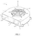
- FIG. 1 is a schematic diagram showing a centrifugal fan F with dual outlets in the same direction according to an embodiment of the invention
- FIG. 2A is an exploded view of the centrifugal fan F of FIG. 1
- the centrifugal fan F includes a fan frame FF, which includes an upper cover 1 and a base plate 3.
- a first air deflector 11 including a first guide portion 111 is disposed on the upper cover 1.
- the first guide portion 111 is configured at one end of the first air deflector 11 extending inward a flow channel 13.
- Two side surfaces of the first air deflector 11, one of which is close to the base plate 3 and the other of which is away from the base plate 3, have different lengths extending toward the flow channel 13.
- one side surface of the first air deflector 11 close to the base plate 3 is shorter than the other side surface of the first air deflector 11 away from the base plate 3, so that a slant surface on the first air deflector 11 is formed as a first guide portion 111.
- the direction from the upper cover 1 to the base plate 3 is defined as an air inlet direction D1.
- An air outlet plane 0 is defined by the opening area surrounded by the upper cover 1 and the base plate 3 and the plane area of the first air deflector 11 disposed at the open end of the fan frame FF.
- An air outlet direction D2 is defined as a direction perpendicular to the air outlet plane O and away from the center of the centrifugal fan F.
- the first air deflector 11 divides the air outlet plane 0 into a first air outlet O1 and a second air outlet 02.
- the first air outlet O1 is located at one side of the first air deflector 11, which is the same as the first guide portion 111, and the second air outlet 02 is located at the opposite side of the first air deflector 11.
- the first air deflector 11 of this embodiment is disposed on the upper cover 1 and extending toward the base plate 3, but this invention is not limited thereto.
- the first air deflector 11 can be disposed on the base plate 3.
- the first air deflector 11, the upper cover 1 and the base plate 3 can be separately manufactured and then assembled by, for example but not limited to, wedging or screwing.
- the first air deflector 11, the upper cover 1 and the base plate 3 can also be integrally formed as one piece.
- the first air deflector 11 can be designed with different lengths or have multiple sections according to the actual requirements.
- the first air deflector 11 includes a first guide portion 111 for decreasing the collision and friction of the airflow and the first air deflector 11.
- An end surface, i.e. the slant surface of the first guide portion 111, includes at least a straight line, at least a curve line or their combination as shown in FIGS. 4 to 4D .
- the end surface, i.e. the slant surface of the first guide portion 111 includes a straight line, but this invention is not limited to this.
- FIG. 2A is an exploded view of the centrifugal fan F with dual outlets in the same direction according to the embodiment of the invention.
- the centrifugal fan F is flipped in a situation of the base plate 3 at the top and the upper cover 1 at the bottom.
- the centrifugal fan F includes an upper cover 1, an impeller 2, a base plate 3 and a motor for driving the impeller 2.
- the configuration of the motor is well known by those skilled persons, so it is not shown in FIG. 2A for making the figure simple and clear.
- the upper cover 1 and the base plate 3 are connected to form an accommodating space S, and the impeller 2 is disposed in the accommodating space S.
- the rotation center I of the impeller 2 is connected to the motor so that the motor can drive the impeller 2 to rotate.
- FIG. 2B is a top view of the upper cover 1 according to the embodiment of the invention.
- the upper cover 1 includes a first air deflector 11 and a second air deflector 12, and the second air deflector 12 is disposed on the side wall near the second air outlet 02 and away from the first air outlet O1.
- One end of the second air deflector 12 disposed adjacent to the second air outlet 02 has a second guide portion 121 for controlling and changing the airflow direction of the second air outlet 02.
- a width L is defined as a length of a straight line, which is passing through the rotation center I of the impeller, from the internal side wall of the fan F to the external side wall of the fan F. To be noted, the width L is not a constant value.
- a counterclockwise airflow close to the second air deflector 12 is defined as a first airflow W1.
- the first airflow W1 After flowing through the flow channel 13 and reaching the first guide portion 111, the first airflow W1 is divided into a first output airflow W2' and a second airflow W2 flowing counterclockwise inside the fan F.
- the second airflow W2 After reaching the second guide portion 121, the second airflow W2 is redirected to form a second output airflow W3.
- the second air deflector 12 has a section with various width L, which is extended into the flow channel 13.
- the width L, excluding the second guide portion 121, close to the second air output 02 is larger, and the width L away from the second air output 02 is smaller. Accordingly, this design can provide a pressing effect to the first airflow W1 in the flow channel 13.
- the second air deflector 12 of this embodiment is disposed on the upper cover 1, but this invention is not limited thereto.
- the second air deflector 12 can be disposed on the base plate 3 based on the actual requirements.
- the second air deflector 12, the upper cover 1 and the base plate 3 can be separately manufactured and then assembled by, for example but not limited to, wedging or screwing.
- the second air deflector 12, the upper cover 1 and the base plate 3 can also be integrally formed as one piece.
- the second air deflector 12 includes a second guide portion 121, which is configured to cooperate with the first air deflector 11. When there are two air output directions, the above configuration can adjust the air output direction of the second output airflow W3 flowing through the second air outlet 02.
- the air output directions of the first output airflow W2' and the second output airflow W3 are in the direction D2.
- this invention is not limited to this.
- the first output airflow W2' and the second output airflow W3 can be in different directions, and their directions can be adjusted by the first air deflector 11 and the second guide portion 121.
- An end surface, i.e. the slant surface of the second guide portion 121 includes at least a straight line, at least a curve line or their combination as shown in the viewing direction of FIG. 2A .
- the end surface, i.e. the slant surface of the second guide portion 121 includes a straight line, but this invention is not limited to this.
- a line from the rotation center I of the impeller 2 to the air output plane 0 and perpendicular to the air output plane O and a line from the rotation center I of the impeller 2 of the impeller 2 to the end of the first air deflector 11 extending inward the flow channel 13 have an included angle ⁇ 1.
- the included angle ⁇ 1 is 70°.
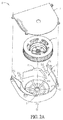
- FIG. 3A is a schematic diagram showing an aspect of the first air deflector of the upper cover 1a. As shown in FIG. 3A , the length of the part of the first air deflector 11 a extending inward the flow channel 13 is increased so as to decrease the air quantity of the first air outlet O1 and to increase the air quantity of the second air outlet 02. In this embodiment, the included angle ⁇ 2 can be 114.5°.
- the second guide portion may have different aspects for changing the airflow direction of the second air outlet 02.
- the second guide portion 121 a has a curved surface.
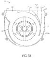
- FIG. 3B is a schematic diagram showing another aspect of a first air deflector of an upper cover 11b.
- the first air deflector 11b is composed of multiple sections.
- the fist air deflector 11b of this embodiment includes a first deflector section 11b1, a second deflector section 11b2 and a third deflector section 11b3.
- the first air deflector 11b of this embodiment is divided into three sections, including the first deflector section 11b1, the second deflector section 11b2 and the third deflector section 11b3, but this invention is not limited to this.
- the first air deflector 11b can be divided into multiple sections depending on the actual requirements or designs.
- FIG. 4A is a schematic diagram showing the end surface, i.e. the slant surface) of the first guide portion 111, viewing from the axial direction of the impeller 2.
- a slant angle ⁇ is the included angle of the end surface of the first guide portion 111 and the axial direction of the impeller 2.
- the slant angle ⁇ ranges from 20° to 50°, and is preferably about 30°.
- the end surface, i.e. the slant surface of the first guide portion 111 is a straight line.
- the first guide portion may have different aspects as shown in FIGS. 4B to 4D .
- the first guide portion 111 a has a concave curved surface.
- the first guide portion 111b has a convex curved surface.
- the first guide portion 111c is composed of at least a straight line and at least a curved line.
- FIG. 5 is a schematic diagram showing the comparison of the test results as the first air deflectors 11 are configured with and without the first guide portion 111.
- the end of the first air deflector 11 extending inward the flow channel is a vertical side wall instead of the above slant surface.
- the air quantity of the centrifugal fan configured with the slant surface is larger than that of the centrifugal fan configured without the slant surface, and the air quantity under the same static pressure or the static pressure under the same air quantity is increased by 20% to 30%.
- the noise intensity of the centrifugal fan configured with the slant surface is 53.5 dB, while the noise intensity of the centrifugal fan configured without the slant surface is 61.0 dB.
- the first air deflector configured with the slant surface can effectively improve the static pressure and air quantity of the centrifugal fan, thereby increasing the heat-dissipating efficiency of the centrifugal fan and decreasing the noise of the centrifugal fan.
- the centrifugal fan with dual outlets in the same direction of the invention has a first air deflector extending inward the flow channel.
- the length of the extending part of the first air deflector can be adjusted based on the requirements, so that the air quantities of the first air outlet and the second air outlet are adjusted accordingly.
- the end of the first air deflector extending into the flow channel has a first guide portion. Accordingly, the centrifugal fan with dual outlets in the same direction is capable of adjusting the air quantities of two air outlets based on the requirements, so that the static pressure and air quantity of the centrifugal fan can be effectively increased for improving the heat-dissipating efficiency of the centrifugal fan and the noise can be reduced as the centrifugal fan is operating.
Landscapes
- Engineering & Computer Science (AREA)
- Mechanical Engineering (AREA)
- General Engineering & Computer Science (AREA)
- Physics & Mathematics (AREA)
- Thermal Sciences (AREA)
- Structures Of Non-Positive Displacement Pumps (AREA)
Abstract
Description
- The present invention relates to a heat-dissipating device and, in particular, to a centrifugal fan.
- As the progress of technology, the electronic devices (e.g. laptop computers) have been developed towards high efficiency, high speed and high frequency, so the calculation loadings of the internal components of the electronic device are sufficiently increased, which is accompanied with higher temperatures. If the heat of the electronic device is not dissipated effectively, the stability of the electronic device will be decreased. In some cases, the lifetime of the electronic device will be reduced. Accordingly, it is a general approach to install a fan inside the electronic device for dissipating the heat of the electronic device.
- The centrifugal fan is one of the most popular heat-dissipating devices. In the centrifugal fan, the cold air enters the air inlet formed on the upper surface of the housing for performing the heat exchange of the electronic device, and then the heated air is outputted through the air outlet formed on the side surface of the fan so as to bring the heat away. During the operation of the centrifugal fan, the impeller rotates at a constant speed so as to cause a periodical pressure change. The pressure change can induce an airflow, which will impact the fan frame or the internal structure of the centrifugal fan, so that the noise is generated.
- In order to enhance the efficiency of the electronic device, the air quantity of the fan must be increased. However, when the air quantity of the fan is increased, the impact intensity of the airflow and the fan frame of the internal structure will be also increased, which causes the lauder noise.
- Therefore, it is an important subject to provide a centrifugal fan that can increase the air quantity and decrease the generation of noise.
- In view of the foregoing, an objective of the present invention is to provide a centrifugal fan with dual air outlets in the same direction that can increase the air quantity and decrease the generation of noise.
- To achieve the above objective, the present invention discloses a centrifugal fan with dual outlets in the same direction, which includes a fan frame, an impeller and a motor. The fan frame includes an upper cover, a base plate and a first air deflector. The base plate and the upper cover are connected to form an accommodating space and an air outlet plane. The first air deflector is arranged near the air outlet plane and divides the air outlet plane into a first air outlet and a second air outlet. The impeller is disposed in the accommodating space. The impeller and the side wall of the fan frame form a flow channel therebetween. The motor connects the impeller and drives it to rotate. The first air deflector extends inward the flow channel from the air outlet plane, and the end of the first air deflector has a first guide portion.
- To achieve the above objective, the present invention also discloses a fan frame of a centrifugal fan with dual outlets in the same direction. The fan frame includes an upper cover, a base plate and a first air deflector. The base plate and the upper cover are connected to form an accommodating space and an air outlet plane. The accommodating space is used for accommodating an impeller, and the impeller and a side wall of the fan frame form a flow channel therebetween. The first air deflector is arranged near the air outlet plane and divides the air outlet plane into a first air outlet and a second air outlet. The first air deflector extends inward the flow channel from the air outlet plane, and an end of the first air deflector extending into the flow channel has a first guide portion.
- In one embodiment, the first air deflector is composed of multiple sections.
- In one embodiment, the first guide portion is a slant surface.
- In one embodiment, the fan frame further includes a second air deflector disposed on a part of the side wall located adjacent to the second air outlet and away from the first air outlet.
- In one embodiment, an end of the second air deflector disposed adjacent to the second air outlet has a second guide portion.
- In one embodiment, an end surface of the second guide portion includes at least a straight line, at least a curve line or their combination.
- In one embodiment, an included angle between a line from a rotation center of the impeller to the end of the first air deflector extending into the flow channel and a line from the rotation center of the impeller to the air outlet plane, which is perpendicular to the air outlet plane, is between 20° and 114.5°.
- In one embodiment, an included angle between axial directions of the first guide portion and the impeller is between 20° and 50°.
- In one embodiment, an end surface of the first guide portion includes at least a straight line, at least a curve line or their combination.
- As mentioned above, the centrifugal fan with dual outlets in the same direction of the invention has a first air deflector extending inward the flow channel. The length of the extending part of the first air deflector can be adjusted based on the requirements, so that the air quantities of the first air outlet and the second air outlet are adjusted accordingly. In addition, the end of the first air deflector extending into the flow channel has a first guide portion. Accordingly, the centrifugal fan with dual outlets in the same direction is capable of adjusting the air quantities of two air outlets based on the requirements, so that the static pressure and air quantity of the centrifugal fan can be effectively increased for improving the heat-dissipating efficiency of the centrifugal fan and the noise can be reduced as the centrifugal fan is operating.
- The present invention will become more fully understood from the subsequent detailed description and accompanying drawings, which are given by way of illustration only, and thus are not limitative of the present invention, and wherein:
-
FIG. 1 is a schematic diagram showing a centrifugal fan with dual outlets in the same direction according to an embodiment of the invention; -
FIG. 2A is an exploded view of the centrifugal fan with dual outlets in the same direction according to the embodiment of the invention; -
FIG. 2B is a schematic diagram showing an upper cover according to the embodiment of the invention; -
FIGS. 3A and3B are schematic diagrams showing different aspects of the first air deflector of the upper cover as shown inFIG. 2B ; -
FIG. 4A is a schematic diagram showing a first guide portion according to the embodiment of the invention; -
FIGS. 4B to 4D are schematic diagrams showing different aspects of the first guide portion according to the embodiment of the invention; and -
FIG. 5 is a schematic diagram showing the comparison of the test results as the first air deflectors are configured with and without the first guide portion. - The embodiments of the invention will be apparent from the following detailed description, which proceeds with reference to the accompanying drawings, wherein the same references relate to the same elements. Moreover, the drawings of all implementation are schematic, and they do not mean the actual size and proportion.
- The terms of direction recited in the disclosure, for example up, down, left, right, front, or rear, only define the directions according to the accompanying drawings for the convenience of explanation but not for limitation.
- The names of elements and the wording recited in the disclosure all have ordinary meanings in the art unless otherwise stated. Therefore, a person skilled in the art can unambiguously understand their meanings.
-
FIG. 1 is a schematic diagram showing a centrifugal fan F with dual outlets in the same direction according to an embodiment of the invention, andFIG. 2A is an exploded view of the centrifugal fan F ofFIG. 1 . Referring toFIGS. 1 and2A , the centrifugal fan F includes a fan frame FF, which includes anupper cover 1 and abase plate 3. Afirst air deflector 11 including afirst guide portion 111 is disposed on theupper cover 1. Thefirst guide portion 111 is configured at one end of thefirst air deflector 11 extending inward aflow channel 13. Two side surfaces of thefirst air deflector 11, one of which is close to thebase plate 3 and the other of which is away from thebase plate 3, have different lengths extending toward theflow channel 13. For example, one side surface of thefirst air deflector 11 close to thebase plate 3 is shorter than the other side surface of thefirst air deflector 11 away from thebase plate 3, so that a slant surface on thefirst air deflector 11 is formed as afirst guide portion 111. As shown inFIG. 1 , the direction from theupper cover 1 to thebase plate 3 is defined as an air inlet direction D1. Anair outlet plane 0 is defined by the opening area surrounded by theupper cover 1 and thebase plate 3 and the plane area of thefirst air deflector 11 disposed at the open end of the fan frame FF. An air outlet direction D2 is defined as a direction perpendicular to the air outlet plane O and away from the center of the centrifugal fan F. Thefirst air deflector 11 divides theair outlet plane 0 into a first air outlet O1 and asecond air outlet 02. The first air outlet O1 is located at one side of thefirst air deflector 11, which is the same as thefirst guide portion 111, and thesecond air outlet 02 is located at the opposite side of thefirst air deflector 11. - To be noted, the
first air deflector 11 of this embodiment is disposed on theupper cover 1 and extending toward thebase plate 3, but this invention is not limited thereto. In practice, thefirst air deflector 11 can be disposed on thebase plate 3. Otherwise, thefirst air deflector 11, theupper cover 1 and thebase plate 3 can be separately manufactured and then assembled by, for example but not limited to, wedging or screwing. Moreover, thefirst air deflector 11, theupper cover 1 and thebase plate 3 can also be integrally formed as one piece. Besides, thefirst air deflector 11 can be designed with different lengths or have multiple sections according to the actual requirements. In addition, thefirst air deflector 11 includes afirst guide portion 111 for decreasing the collision and friction of the airflow and thefirst air deflector 11. An end surface, i.e. the slant surface of thefirst guide portion 111, includes at least a straight line, at least a curve line or their combination as shown inFIGS. 4 to 4D . In this embodiment, the end surface, i.e. the slant surface of thefirst guide portion 111, includes a straight line, but this invention is not limited to this. -
FIG. 2A is an exploded view of the centrifugal fan F with dual outlets in the same direction according to the embodiment of the invention. In order to clearly view the internal arrangement of theupper cover 1, the centrifugal fan F is flipped in a situation of thebase plate 3 at the top and theupper cover 1 at the bottom. As shown inFIG. 2A , the centrifugal fan F includes anupper cover 1, animpeller 2, abase plate 3 and a motor for driving theimpeller 2. The configuration of the motor is well known by those skilled persons, so it is not shown inFIG. 2A for making the figure simple and clear. Theupper cover 1 and thebase plate 3 are connected to form an accommodating space S, and theimpeller 2 is disposed in the accommodating space S. The rotation center I of theimpeller 2 is connected to the motor so that the motor can drive theimpeller 2 to rotate. Theimpeller 2 and the side wall of theupper cover 1, i.e. the internal side wall, form aflow channel 13, as shown inFIG. 2B . -
FIG. 2B is a top view of theupper cover 1 according to the embodiment of the invention. Referring toFIGS. 2A and2B , theupper cover 1 includes afirst air deflector 11 and asecond air deflector 12, and thesecond air deflector 12 is disposed on the side wall near thesecond air outlet 02 and away from the first air outlet O1. One end of thesecond air deflector 12 disposed adjacent to thesecond air outlet 02 has asecond guide portion 121 for controlling and changing the airflow direction of thesecond air outlet 02. A width L is defined as a length of a straight line, which is passing through the rotation center I of the impeller, from the internal side wall of the fan F to the external side wall of the fan F. To be noted, the width L is not a constant value. In order to well understand the airflow direction in the fan F, a counterclockwise airflow close to thesecond air deflector 12 is defined as a first airflow W1. After flowing through theflow channel 13 and reaching thefirst guide portion 111, the first airflow W1 is divided into a first output airflow W2' and a second airflow W2 flowing counterclockwise inside the fan F. After reaching thesecond guide portion 121, the second airflow W2 is redirected to form a second output airflow W3. Thesecond air deflector 12 has a section with various width L, which is extended into theflow channel 13. For example, in the flow area of the first airflow W1, the width L, excluding thesecond guide portion 121, close to thesecond air output 02 is larger, and the width L away from thesecond air output 02 is smaller. Accordingly, this design can provide a pressing effect to the first airflow W1 in theflow channel 13. - To be noted, the
second air deflector 12 of this embodiment is disposed on theupper cover 1, but this invention is not limited thereto. In practice, thesecond air deflector 12 can be disposed on thebase plate 3 based on the actual requirements. Otherwise, thesecond air deflector 12, theupper cover 1 and thebase plate 3 can be separately manufactured and then assembled by, for example but not limited to, wedging or screwing. Moreover, thesecond air deflector 12, theupper cover 1 and thebase plate 3 can also be integrally formed as one piece. Besides, thesecond air deflector 12 includes asecond guide portion 121, which is configured to cooperate with thefirst air deflector 11. When there are two air output directions, the above configuration can adjust the air output direction of the second output airflow W3 flowing through thesecond air outlet 02. For example, the air output directions of the first output airflow W2' and the second output airflow W3 are in the direction D2. Of course, this invention is not limited to this. In another case, the first output airflow W2' and the second output airflow W3 can be in different directions, and their directions can be adjusted by thefirst air deflector 11 and thesecond guide portion 121. An end surface, i.e. the slant surface of thesecond guide portion 121, includes at least a straight line, at least a curve line or their combination as shown in the viewing direction ofFIG. 2A . In this embodiment, the end surface, i.e. the slant surface of thesecond guide portion 121, includes a straight line, but this invention is not limited to this. - A line from the rotation center I of the
impeller 2 to theair output plane 0 and perpendicular to the air output plane O and a line from the rotation center I of theimpeller 2 of theimpeller 2 to the end of thefirst air deflector 11 extending inward theflow channel 13 have an included angle θ1. In this embodiment, the included angle θ1 is 70°. - To adjust the ratio of the air quantities of the first air outlet O1 and the
second air outlet 02, the length of the part of thefirst air deflector 11 extending inward theflow channel 13 can be modified, and the corresponding included angle θ1 can be from 20° to 114.5°.FIG. 3A is a schematic diagram showing an aspect of the first air deflector of the upper cover 1a. As shown inFIG. 3A , the length of the part of thefirst air deflector 11 a extending inward theflow channel 13 is increased so as to decrease the air quantity of the first air outlet O1 and to increase the air quantity of thesecond air outlet 02. In this embodiment, the included angle θ2 can be 114.5°. In addition, the second guide portion may have different aspects for changing the airflow direction of thesecond air outlet 02. In this embodiment, thesecond guide portion 121 a has a curved surface. -
FIG. 3B is a schematic diagram showing another aspect of a first air deflector of anupper cover 11b. As shown inFIG. 3B , thefirst air deflector 11b is composed of multiple sections. For example, thefist air deflector 11b of this embodiment includes a first deflector section 11b1, a second deflector section 11b2 and a third deflector section 11b3. To be noted, thefirst air deflector 11b of this embodiment is divided into three sections, including the first deflector section 11b1, the second deflector section 11b2 and the third deflector section 11b3, but this invention is not limited to this. In practice, thefirst air deflector 11b can be divided into multiple sections depending on the actual requirements or designs. -
FIG. 4A is a schematic diagram showing the end surface, i.e. the slant surface) of thefirst guide portion 111, viewing from the axial direction of theimpeller 2. Referring toFIG. 4A , a slant angle ϕ is the included angle of the end surface of thefirst guide portion 111 and the axial direction of theimpeller 2. The slant angle ϕ ranges from 20° to 50°, and is preferably about 30°. When the centrifugal fan F is in operation, the configuration of the slant angle ϕ can reduce the collision and friction of the airflow and thefirst air deflector 11, thereby decreasing the generated noise. - As shown in
FIG. 4A , the end surface, i.e. the slant surface of thefirst guide portion 111, is a straight line. However, the first guide portion may have different aspects as shown inFIGS. 4B to 4D . As shown inFIG. 4B , thefirst guide portion 111 a has a concave curved surface. As shown inFIG. 4C , thefirst guide portion 111b has a convex curved surface. As shown inFIG. 4D , thefirst guide portion 111c is composed of at least a straight line and at least a curved line. -
FIG. 5 is a schematic diagram showing the comparison of the test results as thefirst air deflectors 11 are configured with and without thefirst guide portion 111. The end of thefirst air deflector 11 extending inward the flow channel is a vertical side wall instead of the above slant surface. With the same test parameters, the same size and rotation speed, the air quantity of the centrifugal fan configured with the slant surface is larger than that of the centrifugal fan configured without the slant surface, and the air quantity under the same static pressure or the static pressure under the same air quantity is increased by 20% to 30%. In the noise intensity test, the noise intensity of the centrifugal fan configured with the slant surface is 53.5 dB, while the noise intensity of the centrifugal fan configured without the slant surface is 61.0 dB. This result indicates that the first air deflector configured with the slant surface can effectively improve the static pressure and air quantity of the centrifugal fan, thereby increasing the heat-dissipating efficiency of the centrifugal fan and decreasing the noise of the centrifugal fan. - In summary, the centrifugal fan with dual outlets in the same direction of the invention has a first air deflector extending inward the flow channel. The length of the extending part of the first air deflector can be adjusted based on the requirements, so that the air quantities of the first air outlet and the second air outlet are adjusted accordingly. In addition, the end of the first air deflector extending into the flow channel has a first guide portion. Accordingly, the centrifugal fan with dual outlets in the same direction is capable of adjusting the air quantities of two air outlets based on the requirements, so that the static pressure and air quantity of the centrifugal fan can be effectively increased for improving the heat-dissipating efficiency of the centrifugal fan and the noise can be reduced as the centrifugal fan is operating.
- Although the present invention has been described with reference to specific embodiments, this description is not meant to be construed in a limiting sense. Various modifications of the disclosed embodiments, as well as alternative embodiments, will be apparent to persons skilled in the art. It is, therefore, contemplated that the appended claims will cover all modifications that fall within the true scope of the present invention.
Claims (15)
- A centrifugal fan with dual outlets in the same direction, comprising:a fan frame comprising an upper cover, a base plate and a first air deflector, wherein the base plate and the upper cover are connected to form an accommodating space and an air outlet plane, and the first air deflector is arranged near the air outlet plane and divides the air outlet plane into a first air outlet and a second air outlet;an impeller disposed in the accommodating space, wherein the impeller and a side wall of the fan frame form a flow channel therebetween; anda motor connecting the impeller and driving it to rotate;wherein the first air deflector extends inward the flow channel from the air outlet plane, and an end of the first air deflector extending into the flow channel has a first guide portion.
- The centrifugal fan of claim 1, wherein the first air deflector is composed of multiple sections.
- The centrifugal fan of claim 1, wherein an end surface of the first guide portion comprises at least a straight line, at least a curve line or their combination.
- The centrifugal fan of claim 1, wherein the fan frame further comprises a second air deflector disposed on a part of the side wall located adjacent to the second air outlet and away from the first air outlet.
- The centrifugal fan of claim 4, wherein an end of the second air deflector disposed adjacent to the second air outlet has a second guide portion.
- The centrifugal fan of claim 5, wherein an end surface of the second guide portion comprises at least a straight line, at least a curve line or their combination.
- The centrifugal fan of claim 1, wherein an included angle between a line from a rotation center of the impeller to the end of the first air deflector extending into the flow channel and a line from the rotation center of the impeller to the air outlet plane, which is perpendicular to the air outlet plane, is between 20° and 114.5°.
- The centrifugal fan of claim 1, wherein an included angle between axial directions of the first guide portion and the impeller is between 20° and 50°.
- A fan frame of a centrifugal fan with dual outlets in the same direction, comprising:an upper cover;a base plate, wherein the base plate and the upper cover are connected to form an accommodating space and an air outlet plane, the accommodating space is used for accommodating an impeller, and the impeller and a side wall of the fan frame form a flow channel therebetween; anda first air deflector arranged near the air outlet plane, wherein the first air deflector divides the air outlet plane into a first air outlet and a second air outlet;wherein the first air deflector extends inward the flow channel from the air outlet plane, and an end of the first air deflector extending into the flow channel has a first guide portion.
- The fan frame of claim 9, wherein the first air deflector is composed of multiple sections.
- The fan frame of claim 9, wherein an end surface of the first guide portion comprises at least a straight line, at least a curve line or their combination.
- The fan frame of claim 9, further comprising:a second air deflector disposed on a part of the side wall located adjacent to the second air outlet and away from the first air outlet.
- The fan frame of claim 12, wherein an end of the second air deflector disposed adjacent to the second air outlet has a second guide portion.
- The fan frame of claim 13, wherein an end surface of the second guide portion comprises at least a straight line, at least a curve line or their combination.
- The fan frame of claim 9, wherein an included angle between a line from a rotation center of the impeller to the end of the first air deflector extending into the flow channel and a line from the rotation center of the impeller to the air outlet plane, which is perpendicular to the air outlet plane, is between 20° and 114.5°.
Applications Claiming Priority (2)
| Application Number | Priority Date | Filing Date | Title |
|---|---|---|---|
| US201562180332P | 2015-06-16 | 2015-06-16 | |
| CN201610301053.6A CN106257057B (en) | 2015-06-16 | 2016-05-09 | Centrifugal fan with dual air outlets in the same direction and its fan frame |
Publications (2)
| Publication Number | Publication Date |
|---|---|
| EP3106667A1 true EP3106667A1 (en) | 2016-12-21 |
| EP3106667B1 EP3106667B1 (en) | 2021-12-15 |
Family
ID=56194237
Family Applications (1)
| Application Number | Title | Priority Date | Filing Date |
|---|---|---|---|
| EP16172515.5A Active EP3106667B1 (en) | 2015-06-16 | 2016-06-01 | Centrifugal fan with dual outlets in the same direction and fan frame thereof |
Country Status (2)
| Country | Link |
|---|---|
| US (1) | US10539150B2 (en) |
| EP (1) | EP3106667B1 (en) |
Cited By (3)
| Publication number | Priority date | Publication date | Assignee | Title |
|---|---|---|---|---|
| CN114198321A (en) * | 2021-12-03 | 2022-03-18 | 合肥联宝信息技术有限公司 | Centrifugal fan with self-adaptive flow channel |
| CN114215771A (en) * | 2021-11-18 | 2022-03-22 | 珠海格力电器股份有限公司 | Air supply structure of a fan and fan |
| EP4442303A3 (en) * | 2016-05-04 | 2024-11-27 | Fisher & Paykel Healthcare Limited | Respiratory support system and blower for respiratory support system |
Families Citing this family (23)
| Publication number | Priority date | Publication date | Assignee | Title |
|---|---|---|---|---|
| US10539150B2 (en) * | 2015-06-16 | 2020-01-21 | Delta Electronics, Inc. | Centrifugal fan with dual outlets in the same direction and fan frame thereof |
| US10443891B2 (en) * | 2016-06-15 | 2019-10-15 | Regal Beloit America, Inc. | Water heater blower assembly having a low exhaust port |
| US11306944B2 (en) | 2016-06-15 | 2022-04-19 | Regal Beloit America, Inc. | Water heater blower assembly having a low exhaust port |
| CN107869033B (en) * | 2016-09-26 | 2020-10-02 | 青岛胶南海尔洗衣机有限公司 | A kind of forward and reverse fan for clothes dryer and clothes dryer |
| KR102341728B1 (en) * | 2017-03-21 | 2021-12-22 | 삼성전자주식회사 | Air conditioner |
| KR102404660B1 (en) * | 2017-09-01 | 2022-06-02 | 엘지전자 주식회사 | Flow generator |
| CN110118198B (en) * | 2018-02-05 | 2021-03-02 | 华硕电脑股份有限公司 | Centrifugal fan |
| US10584717B1 (en) * | 2019-04-25 | 2020-03-10 | Dell Products, Lp | Blower system with dual opposite outlets and fan diameter approaching to blower housing dimension for information handling systems |
| US11109509B2 (en) | 2019-05-03 | 2021-08-31 | Dell Products, Lp | Cooling module with blower system having dual opposite outlets for information handling systems |
| US10969838B2 (en) * | 2019-09-05 | 2021-04-06 | Dell Products, L.P. | Hybrid cooling system with multiple outlet blowers |
| US11028857B2 (en) | 2019-09-18 | 2021-06-08 | Dell Products, Lp | Cooling module with blower system having opposite, blower and impeller outlets for information handling systems |
| TWM588906U (en) * | 2019-09-26 | 2020-01-01 | 藍天電腦股份有限公司 | Laptop computer dustproof device |
| DE102020203422B4 (en) * | 2020-03-17 | 2024-02-01 | Dometic Sweden Ab | Heating device, recreational vehicle with heating device and method for heating fluids in a recreational vehicle |
| US11578731B2 (en) * | 2020-06-15 | 2023-02-14 | Delta Electronics, Inc. | Asymmetrical double-outlet blower |
| US12055149B2 (en) | 2020-07-16 | 2024-08-06 | Dell Products Lp | Blower fan with through hole and fan support rod |
| US11240931B1 (en) | 2020-07-16 | 2022-02-01 | Dell Products, Lp | Variable height fan |
| US11994144B2 (en) | 2020-10-30 | 2024-05-28 | Dell Products Lp | Blower system with an inner axial fan blade set and an outer centrifugal fan blade set |
| GB2639317A (en) * | 2021-06-04 | 2025-09-24 | Shenzhen Jisu Tech Co Ltd | Hanging neck fan |
| US11665852B2 (en) * | 2021-09-10 | 2023-05-30 | Dell Products L.P. | Information handling system fan having a concave housing |
| CN114607644B (en) * | 2022-04-01 | 2023-11-03 | 石家庄东方热电热力工程有限公司 | Heat radiation unit for electric device |
| CN115750451A (en) * | 2022-11-25 | 2023-03-07 | 景德镇陶瓷大学 | Electronic transformer and cooling fan thereof |
| TWI874175B (en) * | 2024-03-29 | 2025-02-21 | 英業達股份有限公司 | Fan frame with passageway |
| CN121346334B (en) * | 2025-12-17 | 2026-04-14 | 昆山奕昕电机科技有限公司 | Negative ion air purification circulation fan |
Citations (4)
| Publication number | Priority date | Publication date | Assignee | Title |
|---|---|---|---|---|
| US20050163607A1 (en) * | 2004-01-23 | 2005-07-28 | Airex Inc. | Blower with double inlet wheel |
| US20070160462A1 (en) * | 2006-01-11 | 2007-07-12 | Delta Electronics, Inc. | Centrifugal fan and fan frame thereof |
| US20110250065A1 (en) * | 2010-04-09 | 2011-10-13 | Foxconn Technology Co., Ltd. | Centrifugal fan |
| US20130101449A1 (en) * | 2011-10-20 | 2013-04-25 | Roger Dickinson | Double Inlet Centrifugal Blower with Peripheral Motor |
Family Cites Families (11)
| Publication number | Priority date | Publication date | Assignee | Title |
|---|---|---|---|---|
| US4944654A (en) * | 1989-05-15 | 1990-07-31 | Carrier Corporation | Split scroll for centrifugal blower |
| JPH04350400A (en) * | 1991-05-27 | 1992-12-04 | Hitachi Ltd | centrifugal blower |
| US5738492A (en) * | 1996-07-09 | 1998-04-14 | White Consolidated Industries, Inc. | Constant velocity air foil |
| US5837020A (en) * | 1997-06-20 | 1998-11-17 | Hmi Industries, Inc. | Room air cleaner |
| JP2003023281A (en) * | 2001-07-05 | 2003-01-24 | Toshiba Corp | Electronic equipment with built-in heating element and air-cooled cooling device |
| US20060078423A1 (en) * | 2004-10-08 | 2006-04-13 | Nonlinear Tech, Inc. | Bi-directional Blowers for Cooling Laptop Computers |
| US7802617B2 (en) * | 2006-07-14 | 2010-09-28 | Fu Zhun Precision Industry (Shen Zhen) Co., Ltd. | Heat dissipation apparatus |
| CN101676569A (en) * | 2008-09-19 | 2010-03-24 | 富准精密工业(深圳)有限公司 | Heat sink and centrifugal fan applied by same |
| CN102478025B (en) * | 2010-11-29 | 2016-04-27 | 富瑞精密组件(昆山)有限公司 | Sink and centrifugal cutter thereof |
| CN102230480B (en) * | 2011-07-08 | 2013-07-03 | 上海交通大学 | Compact single-suction centrifugal fan |
| US10539150B2 (en) * | 2015-06-16 | 2020-01-21 | Delta Electronics, Inc. | Centrifugal fan with dual outlets in the same direction and fan frame thereof |
-
2016
- 2016-05-31 US US15/168,443 patent/US10539150B2/en active Active
- 2016-06-01 EP EP16172515.5A patent/EP3106667B1/en active Active
Patent Citations (4)
| Publication number | Priority date | Publication date | Assignee | Title |
|---|---|---|---|---|
| US20050163607A1 (en) * | 2004-01-23 | 2005-07-28 | Airex Inc. | Blower with double inlet wheel |
| US20070160462A1 (en) * | 2006-01-11 | 2007-07-12 | Delta Electronics, Inc. | Centrifugal fan and fan frame thereof |
| US20110250065A1 (en) * | 2010-04-09 | 2011-10-13 | Foxconn Technology Co., Ltd. | Centrifugal fan |
| US20130101449A1 (en) * | 2011-10-20 | 2013-04-25 | Roger Dickinson | Double Inlet Centrifugal Blower with Peripheral Motor |
Cited By (4)
| Publication number | Priority date | Publication date | Assignee | Title |
|---|---|---|---|---|
| EP4442303A3 (en) * | 2016-05-04 | 2024-11-27 | Fisher & Paykel Healthcare Limited | Respiratory support system and blower for respiratory support system |
| CN114215771A (en) * | 2021-11-18 | 2022-03-22 | 珠海格力电器股份有限公司 | Air supply structure of a fan and fan |
| CN114198321A (en) * | 2021-12-03 | 2022-03-18 | 合肥联宝信息技术有限公司 | Centrifugal fan with self-adaptive flow channel |
| CN114198321B (en) * | 2021-12-03 | 2023-10-27 | 合肥联宝信息技术有限公司 | Centrifugal fan with self-adaptive runner |
Also Published As
| Publication number | Publication date |
|---|---|
| US10539150B2 (en) | 2020-01-21 |
| US20160369811A1 (en) | 2016-12-22 |
| EP3106667B1 (en) | 2021-12-15 |
Similar Documents
| Publication | Publication Date | Title |
|---|---|---|
| US10539150B2 (en) | Centrifugal fan with dual outlets in the same direction and fan frame thereof | |
| US9322413B2 (en) | Centrifugal fan | |
| TWI537481B (en) | Centrifugal fan | |
| CN106257057B (en) | Centrifugal fan with dual air outlets in the same direction and its fan frame | |
| US20130115066A1 (en) | Centrifugal fan | |
| US20080011461A1 (en) | Heat dissipation apparatus | |
| CN101377206B (en) | Fan vane structure and centrifugal fan having the same | |
| US11913472B2 (en) | Centrifugal heat dissipation fan and heat dissipation system of electronic device | |
| CN110017293B (en) | centrifugal fan | |
| CN108869337B (en) | fan | |
| US12025143B2 (en) | Mixed flow fan with enhanced heat dissipation efficiency | |
| US11162498B2 (en) | Fan | |
| US20210219457A1 (en) | Electronic device | |
| TW201440625A (en) | Thermal module | |
| US9222482B2 (en) | Centrifugal fan | |
| CN104662303B (en) | Air conditioner | |
| CN116201752A (en) | Heat sink assembly | |
| US20050207886A1 (en) | Centrifugal fan and fan frame thereof | |
| US20050025621A1 (en) | Airflow guiding structure for a heat-dissipating fan | |
| US10718342B2 (en) | Centrifugal fan comprising a sidewall and plurality of air deflectors forming a plurality of airflow entry tunnels to sequentially expand a flow channel outwardly in a radial direction | |
| CN103727066B (en) | Centrifugal fan | |
| US20080055853A1 (en) | Heat dissipating module and assembly of the heat dissipating module and a computer housing | |
| US20090169373A1 (en) | Centrifugal blower and bottom housing thereof | |
| US7828510B2 (en) | Fan | |
| US7192249B2 (en) | Turbulent flow blower |
Legal Events
| Date | Code | Title | Description |
|---|---|---|---|
| PUAI | Public reference made under article 153(3) epc to a published international application that has entered the european phase |
Free format text: ORIGINAL CODE: 0009012 |
|
| STAA | Information on the status of an ep patent application or granted ep patent |
Free format text: STATUS: THE APPLICATION HAS BEEN PUBLISHED |
|
| AK | Designated contracting states |
Kind code of ref document: A1 Designated state(s): AL AT BE BG CH CY CZ DE DK EE ES FI FR GB GR HR HU IE IS IT LI LT LU LV MC MK MT NL NO PL PT RO RS SE SI SK SM TR |
|
| AX | Request for extension of the european patent |
Extension state: BA ME |
|
| STAA | Information on the status of an ep patent application or granted ep patent |
Free format text: STATUS: REQUEST FOR EXAMINATION WAS MADE |
|
| 17P | Request for examination filed |
Effective date: 20170614 |
|
| RBV | Designated contracting states (corrected) |
Designated state(s): AL AT BE BG CH CY CZ DE DK EE ES FI FR GB GR HR HU IE IS IT LI LT LU LV MC MK MT NL NO PL PT RO RS SE SI SK SM TR |
|
| STAA | Information on the status of an ep patent application or granted ep patent |
Free format text: STATUS: EXAMINATION IS IN PROGRESS |
|
| 17Q | First examination report despatched |
Effective date: 20201020 |
|
| GRAP | Despatch of communication of intention to grant a patent |
Free format text: ORIGINAL CODE: EPIDOSNIGR1 |
|
| STAA | Information on the status of an ep patent application or granted ep patent |
Free format text: STATUS: GRANT OF PATENT IS INTENDED |
|
| INTG | Intention to grant announced |
Effective date: 20210623 |
|
| GRAS | Grant fee paid |
Free format text: ORIGINAL CODE: EPIDOSNIGR3 |
|
| GRAA | (expected) grant |
Free format text: ORIGINAL CODE: 0009210 |
|
| STAA | Information on the status of an ep patent application or granted ep patent |
Free format text: STATUS: THE PATENT HAS BEEN GRANTED |
|
| AK | Designated contracting states |
Kind code of ref document: B1 Designated state(s): AL AT BE BG CH CY CZ DE DK EE ES FI FR GB GR HR HU IE IS IT LI LT LU LV MC MK MT NL NO PL PT RO RS SE SI SK SM TR |
|
| REG | Reference to a national code |
Ref country code: GB Ref legal event code: FG4D Ref country code: CH Ref legal event code: EP |
|
| REG | Reference to a national code |
Ref country code: IE Ref legal event code: FG4D Ref country code: DE Ref legal event code: R096 Ref document number: 602016067312 Country of ref document: DE |
|
| REG | Reference to a national code |
Ref country code: AT Ref legal event code: REF Ref document number: 1455683 Country of ref document: AT Kind code of ref document: T Effective date: 20220115 |
|
| REG | Reference to a national code |
Ref country code: LT Ref legal event code: MG9D |
|
| REG | Reference to a national code |
Ref country code: NL Ref legal event code: MP Effective date: 20211215 |
|
| PG25 | Lapsed in a contracting state [announced via postgrant information from national office to epo] |
Ref country code: RS Free format text: LAPSE BECAUSE OF FAILURE TO SUBMIT A TRANSLATION OF THE DESCRIPTION OR TO PAY THE FEE WITHIN THE PRESCRIBED TIME-LIMIT Effective date: 20211215 Ref country code: LT Free format text: LAPSE BECAUSE OF FAILURE TO SUBMIT A TRANSLATION OF THE DESCRIPTION OR TO PAY THE FEE WITHIN THE PRESCRIBED TIME-LIMIT Effective date: 20211215 Ref country code: FI Free format text: LAPSE BECAUSE OF FAILURE TO SUBMIT A TRANSLATION OF THE DESCRIPTION OR TO PAY THE FEE WITHIN THE PRESCRIBED TIME-LIMIT Effective date: 20211215 Ref country code: BG Free format text: LAPSE BECAUSE OF FAILURE TO SUBMIT A TRANSLATION OF THE DESCRIPTION OR TO PAY THE FEE WITHIN THE PRESCRIBED TIME-LIMIT Effective date: 20220315 |
|
| REG | Reference to a national code |
Ref country code: AT Ref legal event code: MK05 Ref document number: 1455683 Country of ref document: AT Kind code of ref document: T Effective date: 20211215 |
|
| PG25 | Lapsed in a contracting state [announced via postgrant information from national office to epo] |
Ref country code: SE Free format text: LAPSE BECAUSE OF FAILURE TO SUBMIT A TRANSLATION OF THE DESCRIPTION OR TO PAY THE FEE WITHIN THE PRESCRIBED TIME-LIMIT Effective date: 20211215 Ref country code: NO Free format text: LAPSE BECAUSE OF FAILURE TO SUBMIT A TRANSLATION OF THE DESCRIPTION OR TO PAY THE FEE WITHIN THE PRESCRIBED TIME-LIMIT Effective date: 20220315 Ref country code: LV Free format text: LAPSE BECAUSE OF FAILURE TO SUBMIT A TRANSLATION OF THE DESCRIPTION OR TO PAY THE FEE WITHIN THE PRESCRIBED TIME-LIMIT Effective date: 20211215 Ref country code: HR Free format text: LAPSE BECAUSE OF FAILURE TO SUBMIT A TRANSLATION OF THE DESCRIPTION OR TO PAY THE FEE WITHIN THE PRESCRIBED TIME-LIMIT Effective date: 20211215 Ref country code: GR Free format text: LAPSE BECAUSE OF FAILURE TO SUBMIT A TRANSLATION OF THE DESCRIPTION OR TO PAY THE FEE WITHIN THE PRESCRIBED TIME-LIMIT Effective date: 20220316 |
|
| PG25 | Lapsed in a contracting state [announced via postgrant information from national office to epo] |
Ref country code: NL Free format text: LAPSE BECAUSE OF FAILURE TO SUBMIT A TRANSLATION OF THE DESCRIPTION OR TO PAY THE FEE WITHIN THE PRESCRIBED TIME-LIMIT Effective date: 20211215 |
|
| PG25 | Lapsed in a contracting state [announced via postgrant information from national office to epo] |
Ref country code: SM Free format text: LAPSE BECAUSE OF FAILURE TO SUBMIT A TRANSLATION OF THE DESCRIPTION OR TO PAY THE FEE WITHIN THE PRESCRIBED TIME-LIMIT Effective date: 20211215 Ref country code: SK Free format text: LAPSE BECAUSE OF FAILURE TO SUBMIT A TRANSLATION OF THE DESCRIPTION OR TO PAY THE FEE WITHIN THE PRESCRIBED TIME-LIMIT Effective date: 20211215 Ref country code: RO Free format text: LAPSE BECAUSE OF FAILURE TO SUBMIT A TRANSLATION OF THE DESCRIPTION OR TO PAY THE FEE WITHIN THE PRESCRIBED TIME-LIMIT Effective date: 20211215 Ref country code: PT Free format text: LAPSE BECAUSE OF FAILURE TO SUBMIT A TRANSLATION OF THE DESCRIPTION OR TO PAY THE FEE WITHIN THE PRESCRIBED TIME-LIMIT Effective date: 20220418 Ref country code: ES Free format text: LAPSE BECAUSE OF FAILURE TO SUBMIT A TRANSLATION OF THE DESCRIPTION OR TO PAY THE FEE WITHIN THE PRESCRIBED TIME-LIMIT Effective date: 20211215 Ref country code: EE Free format text: LAPSE BECAUSE OF FAILURE TO SUBMIT A TRANSLATION OF THE DESCRIPTION OR TO PAY THE FEE WITHIN THE PRESCRIBED TIME-LIMIT Effective date: 20211215 Ref country code: CZ Free format text: LAPSE BECAUSE OF FAILURE TO SUBMIT A TRANSLATION OF THE DESCRIPTION OR TO PAY THE FEE WITHIN THE PRESCRIBED TIME-LIMIT Effective date: 20211215 |
|
| PG25 | Lapsed in a contracting state [announced via postgrant information from national office to epo] |
Ref country code: PL Free format text: LAPSE BECAUSE OF FAILURE TO SUBMIT A TRANSLATION OF THE DESCRIPTION OR TO PAY THE FEE WITHIN THE PRESCRIBED TIME-LIMIT Effective date: 20211215 Ref country code: AT Free format text: LAPSE BECAUSE OF FAILURE TO SUBMIT A TRANSLATION OF THE DESCRIPTION OR TO PAY THE FEE WITHIN THE PRESCRIBED TIME-LIMIT Effective date: 20211215 |
|
| REG | Reference to a national code |
Ref country code: DE Ref legal event code: R097 Ref document number: 602016067312 Country of ref document: DE |
|
| PG25 | Lapsed in a contracting state [announced via postgrant information from national office to epo] |
Ref country code: IS Free format text: LAPSE BECAUSE OF FAILURE TO SUBMIT A TRANSLATION OF THE DESCRIPTION OR TO PAY THE FEE WITHIN THE PRESCRIBED TIME-LIMIT Effective date: 20220415 |
|
| PLBE | No opposition filed within time limit |
Free format text: ORIGINAL CODE: 0009261 |
|
| STAA | Information on the status of an ep patent application or granted ep patent |
Free format text: STATUS: NO OPPOSITION FILED WITHIN TIME LIMIT |
|
| PG25 | Lapsed in a contracting state [announced via postgrant information from national office to epo] |
Ref country code: DK Free format text: LAPSE BECAUSE OF FAILURE TO SUBMIT A TRANSLATION OF THE DESCRIPTION OR TO PAY THE FEE WITHIN THE PRESCRIBED TIME-LIMIT Effective date: 20211215 Ref country code: AL Free format text: LAPSE BECAUSE OF FAILURE TO SUBMIT A TRANSLATION OF THE DESCRIPTION OR TO PAY THE FEE WITHIN THE PRESCRIBED TIME-LIMIT Effective date: 20211215 |
|
| 26N | No opposition filed |
Effective date: 20220916 |
|
| PG25 | Lapsed in a contracting state [announced via postgrant information from national office to epo] |
Ref country code: SI Free format text: LAPSE BECAUSE OF FAILURE TO SUBMIT A TRANSLATION OF THE DESCRIPTION OR TO PAY THE FEE WITHIN THE PRESCRIBED TIME-LIMIT Effective date: 20211215 |
|
| PG25 | Lapsed in a contracting state [announced via postgrant information from national office to epo] |
Ref country code: MC Free format text: LAPSE BECAUSE OF FAILURE TO SUBMIT A TRANSLATION OF THE DESCRIPTION OR TO PAY THE FEE WITHIN THE PRESCRIBED TIME-LIMIT Effective date: 20211215 |
|
| REG | Reference to a national code |
Ref country code: CH Ref legal event code: PL |
|
| REG | Reference to a national code |
Ref country code: BE Ref legal event code: MM Effective date: 20220630 |
|
| GBPC | Gb: european patent ceased through non-payment of renewal fee |
Effective date: 20220601 |
|
| PG25 | Lapsed in a contracting state [announced via postgrant information from national office to epo] |
Ref country code: LU Free format text: LAPSE BECAUSE OF NON-PAYMENT OF DUE FEES Effective date: 20220601 Ref country code: LI Free format text: LAPSE BECAUSE OF NON-PAYMENT OF DUE FEES Effective date: 20220630 Ref country code: IE Free format text: LAPSE BECAUSE OF NON-PAYMENT OF DUE FEES Effective date: 20220601 Ref country code: FR Free format text: LAPSE BECAUSE OF NON-PAYMENT OF DUE FEES Effective date: 20220630 Ref country code: CH Free format text: LAPSE BECAUSE OF NON-PAYMENT OF DUE FEES Effective date: 20220630 |
|
| PG25 | Lapsed in a contracting state [announced via postgrant information from national office to epo] |
Ref country code: IT Free format text: LAPSE BECAUSE OF FAILURE TO SUBMIT A TRANSLATION OF THE DESCRIPTION OR TO PAY THE FEE WITHIN THE PRESCRIBED TIME-LIMIT Effective date: 20211215 Ref country code: GB Free format text: LAPSE BECAUSE OF NON-PAYMENT OF DUE FEES Effective date: 20220601 Ref country code: BE Free format text: LAPSE BECAUSE OF NON-PAYMENT OF DUE FEES Effective date: 20220630 |
|
| PG25 | Lapsed in a contracting state [announced via postgrant information from national office to epo] |
Ref country code: HU Free format text: LAPSE BECAUSE OF FAILURE TO SUBMIT A TRANSLATION OF THE DESCRIPTION OR TO PAY THE FEE WITHIN THE PRESCRIBED TIME-LIMIT; INVALID AB INITIO Effective date: 20160601 |
|
| PG25 | Lapsed in a contracting state [announced via postgrant information from national office to epo] |
Ref country code: MK Free format text: LAPSE BECAUSE OF FAILURE TO SUBMIT A TRANSLATION OF THE DESCRIPTION OR TO PAY THE FEE WITHIN THE PRESCRIBED TIME-LIMIT Effective date: 20211215 Ref country code: CY Free format text: LAPSE BECAUSE OF FAILURE TO SUBMIT A TRANSLATION OF THE DESCRIPTION OR TO PAY THE FEE WITHIN THE PRESCRIBED TIME-LIMIT Effective date: 20211215 |
|
| PG25 | Lapsed in a contracting state [announced via postgrant information from national office to epo] |
Ref country code: TR Free format text: LAPSE BECAUSE OF FAILURE TO SUBMIT A TRANSLATION OF THE DESCRIPTION OR TO PAY THE FEE WITHIN THE PRESCRIBED TIME-LIMIT Effective date: 20211215 |
|
| PG25 | Lapsed in a contracting state [announced via postgrant information from national office to epo] |
Ref country code: MT Free format text: LAPSE BECAUSE OF FAILURE TO SUBMIT A TRANSLATION OF THE DESCRIPTION OR TO PAY THE FEE WITHIN THE PRESCRIBED TIME-LIMIT Effective date: 20211215 |
|
| PGFP | Annual fee paid to national office [announced via postgrant information from national office to epo] |
Ref country code: DE Payment date: 20250627 Year of fee payment: 10 |