EP3106658B1 - Object, in particular a rotor blade for a wind turbine - Google Patents
Object, in particular a rotor blade for a wind turbine Download PDFInfo
- Publication number
- EP3106658B1 EP3106658B1 EP15172558.7A EP15172558A EP3106658B1 EP 3106658 B1 EP3106658 B1 EP 3106658B1 EP 15172558 A EP15172558 A EP 15172558A EP 3106658 B1 EP3106658 B1 EP 3106658B1
- Authority
- EP
- European Patent Office
- Prior art keywords
- luminescent material
- fabric
- layers
- layer
- portions
- Prior art date
- Legal status (The legal status is an assumption and is not a legal conclusion. Google has not performed a legal analysis and makes no representation as to the accuracy of the status listed.)
- Not-in-force
Links
- 239000000463 material Substances 0.000 claims description 102
- 239000004744 fabric Substances 0.000 claims description 59
- 239000011159 matrix material Substances 0.000 claims description 17
- 238000000034 method Methods 0.000 claims description 14
- 239000002131 composite material Substances 0.000 claims description 9
- 238000010276 construction Methods 0.000 claims description 9
- 229920000728 polyester Polymers 0.000 claims description 5
- 239000000835 fiber Substances 0.000 claims description 2
- 239000011521 glass Substances 0.000 claims description 2
- 239000010410 layer Substances 0.000 description 73
- 230000005855 radiation Effects 0.000 description 6
- 230000001066 destructive effect Effects 0.000 description 5
- 238000004519 manufacturing process Methods 0.000 description 5
- 230000003287 optical effect Effects 0.000 description 4
- 239000002356 single layer Substances 0.000 description 4
- 238000011179 visual inspection Methods 0.000 description 4
- 238000003909 pattern recognition Methods 0.000 description 3
- 238000009958 sewing Methods 0.000 description 3
- 229920001225 polyester resin Polymers 0.000 description 2
- 239000004645 polyester resin Substances 0.000 description 2
- 230000004936 stimulating effect Effects 0.000 description 2
- 238000012360 testing method Methods 0.000 description 2
- 238000001429 visible spectrum Methods 0.000 description 2
- 229920002430 Fibre-reinforced plastic Polymers 0.000 description 1
- 230000003628 erosive effect Effects 0.000 description 1
- 238000011156 evaluation Methods 0.000 description 1
- 230000005284 excitation Effects 0.000 description 1
- 239000003365 glass fiber Substances 0.000 description 1
- 238000010438 heat treatment Methods 0.000 description 1
- 238000002329 infrared spectrum Methods 0.000 description 1
- 238000012544 monitoring process Methods 0.000 description 1
- 238000001228 spectrum Methods 0.000 description 1
- 230000000007 visual effect Effects 0.000 description 1
- 238000009941 weaving Methods 0.000 description 1
Images

Classifications
-
- F—MECHANICAL ENGINEERING; LIGHTING; HEATING; WEAPONS; BLASTING
- F03—MACHINES OR ENGINES FOR LIQUIDS; WIND, SPRING, OR WEIGHT MOTORS; PRODUCING MECHANICAL POWER OR A REACTIVE PROPULSIVE THRUST, NOT OTHERWISE PROVIDED FOR
- F03D—WIND MOTORS
- F03D1/00—Wind motors with rotation axis substantially parallel to the air flow entering the rotor
- F03D1/06—Rotors
- F03D1/065—Rotors characterised by their construction elements
- F03D1/0675—Rotors characterised by their construction elements of the blades
-
- F—MECHANICAL ENGINEERING; LIGHTING; HEATING; WEAPONS; BLASTING
- F03—MACHINES OR ENGINES FOR LIQUIDS; WIND, SPRING, OR WEIGHT MOTORS; PRODUCING MECHANICAL POWER OR A REACTIVE PROPULSIVE THRUST, NOT OTHERWISE PROVIDED FOR
- F03D—WIND MOTORS
- F03D17/00—Monitoring or testing of wind motors, e.g. diagnostics
-
- F—MECHANICAL ENGINEERING; LIGHTING; HEATING; WEAPONS; BLASTING
- F05—INDEXING SCHEMES RELATING TO ENGINES OR PUMPS IN VARIOUS SUBCLASSES OF CLASSES F01-F04
- F05B—INDEXING SCHEME RELATING TO WIND, SPRING, WEIGHT, INERTIA OR LIKE MOTORS, TO MACHINES OR ENGINES FOR LIQUIDS COVERED BY SUBCLASSES F03B, F03D AND F03G
- F05B2240/00—Components
- F05B2240/99—Components characterised by colour or colour patterns
-
- F—MECHANICAL ENGINEERING; LIGHTING; HEATING; WEAPONS; BLASTING
- F05—INDEXING SCHEMES RELATING TO ENGINES OR PUMPS IN VARIOUS SUBCLASSES OF CLASSES F01-F04
- F05B—INDEXING SCHEME RELATING TO WIND, SPRING, WEIGHT, INERTIA OR LIKE MOTORS, TO MACHINES OR ENGINES FOR LIQUIDS COVERED BY SUBCLASSES F03B, F03D AND F03G
- F05B2280/00—Materials; Properties thereof
- F05B2280/50—Intrinsic material properties or characteristics
-
- F—MECHANICAL ENGINEERING; LIGHTING; HEATING; WEAPONS; BLASTING
- F05—INDEXING SCHEMES RELATING TO ENGINES OR PUMPS IN VARIOUS SUBCLASSES OF CLASSES F01-F04
- F05B—INDEXING SCHEME RELATING TO WIND, SPRING, WEIGHT, INERTIA OR LIKE MOTORS, TO MACHINES OR ENGINES FOR LIQUIDS COVERED BY SUBCLASSES F03B, F03D AND F03G
- F05B2280/00—Materials; Properties thereof
- F05B2280/60—Properties or characteristics given to material by treatment or manufacturing
- F05B2280/6001—Fabrics
-
- Y—GENERAL TAGGING OF NEW TECHNOLOGICAL DEVELOPMENTS; GENERAL TAGGING OF CROSS-SECTIONAL TECHNOLOGIES SPANNING OVER SEVERAL SECTIONS OF THE IPC; TECHNICAL SUBJECTS COVERED BY FORMER USPC CROSS-REFERENCE ART COLLECTIONS [XRACs] AND DIGESTS
- Y02—TECHNOLOGIES OR APPLICATIONS FOR MITIGATION OR ADAPTATION AGAINST CLIMATE CHANGE
- Y02E—REDUCTION OF GREENHOUSE GAS [GHG] EMISSIONS, RELATED TO ENERGY GENERATION, TRANSMISSION OR DISTRIBUTION
- Y02E10/00—Energy generation through renewable energy sources
- Y02E10/70—Wind energy
- Y02E10/72—Wind turbines with rotation axis in wind direction
Definitions
- the invention relates to an object, in particular a rotor blade for a wind turbine, with a composite construction comprising a plurality of layers of fabric arranged in a matrix material.
- composite constructions comprising a plurality of layers of fabric arranged in a matrix material is well known in the prior art.
- rotor blades for wind turbines are built in such a manner.
- the fabric is arranged in a cavity according to the desired shape of the rotor blade.
- a vacuum is applied and subsequently the matrix material is filled into the cavity. Afterwards the rotor blade can be cured, for example by time expired heating.
- WO 2012/110041 A1 discloses a system and a method for detecting damage to a wind turbine blade, that uses one or more fluorescent optical fibres comprising a fluorescent material having an excitation wavelength that is selected such that the material fluoresces upon exposure to ambient radiation. It is therefore possible to ascertain a damage to the wind turbine blade as an optical detector detects radiation emitted by the fluorescent optical fibres, as they emit radiation only when cracks or damages, e. g. based on erosion, are present on the said wind turbine blade.
- the inventive object is composed of a composite construction comprising a plurality of layers of fabric arranged in a matrix material, whereby luminescent material is used to separate at least two layers from each other or to locate the position of one layer which has luminescent material attached thereto or which comprises luminescent material inside the object or inside the matrix material.
- the present invention pursues the idea, that by using luminescent material, it is possible to count the number of layers in the matrix material, as the fabric and the matrix material is as well transparent to visible light and to light that is able to stimulate the luminescent material. Therefore a light source is used, that is capable of stimulating the luminescent material. When the object is exposed to said light source only the stimulated luminescent material emits radiation and the portions of luminescent material are therefore visible and can be counted, while the rest of the object remains transparent.
- each layer of fabric comprises at least one portion comprising luminescent material or having luminescent material attached thereto.
- the layers of fabric can be counted easily as each layer comprises a portion comprising luminescent material or having luminescent material attached thereto.
- the portion of each layer of fabric is made visible. Therefore the single lit up portions of every layer can be counted by visual inspection. Consequently the object does not have to be cut open and can be examined in a non-destructive way.
- At least one layer comprises at least two portions comprising luminescent material or having luminescent material attached thereto, whereby the portions are arranged in a defined distance over the length of the object.
- the portions are arranged close to the edge of the layer in any arbitrary distance, for example 2cm or more, from the edge of the layer and can be arranged at all positions over the width or the length of the layer of fabric.
- the luminescent material in particular the fluorescent yarn, is preferably as wide as the fabric material or the fabric roll, respectively. It is again ensured, that the orientation of the luminescent material applied to each layer of fabric can be aligned in every arbitrary direction. It is in particular possible to apply the luminescent material alongside the length or the width of each layer of fabric.
- the luminescent material is a fluorescent or a phosphorescent or a scintillation material.
- the material used can be chosen user-defined and in general every material is usable that can be stimulated by an adequate light source in such a way, that luminescent material is made visible preferably with light comprising a wavelength outlying the visual spectrum.
- the term luminescent material refers generally to every material that is stimulated by light of an adequate wavelength. As the object in particular a rotor blade for a wind turbine is coated or painted or the surface of the object is processed in any other way, the luminescent material inside the object is not visible in the completed object.
- the material used is yarn or thread or fibre or texture, in particular fluorescent polyester yarn.
- the material can therefore be applied in a fine line or any user-defined pattern on each layer of fabric.
- polyester yarn can be used.
- the polyester yarn is used extensively for example in apparel and home furnishings. It is also well known, that the yarn or thread can be fabricated to be already luminescent. Therefore the luminescent material in form of yarn or thread is widely available and inexpensive.
- the luminescent material is sewn or stitched or woven into at least one layer of fabric.
- This variant can simplify the production of the inventive object further, as the layers of fabric are each sewn, stitched or woven together in a production process, so that these layers consist of fibres sewn, stitched or woven together.
- one sewing or stitching has to be applied or exchanged with one luminescent material, for example luminescent yarn or thread. It is therefore possible, to replace for example a single sewing or stitching per layer with yarn or thread of luminescent material. It is further possible to replace the stitching in a defined cycle, e. g. every one hundred, with luminescent material.
- the luminescent material in that way comprises luminescent material or has luminescent material attached thereto with low production effort.
- the luminescent material can be printed onto the layer of fabric. It is for example possible to print a screen print or any other form or texture onto the layer that consists or is made of luminescent material. Hence nearly any pattern or form is applicable to the layers of fabric.
- the object is preferably composed of a plurality of layers of fabric and of matrix material that are transparent for visible light. Therefore for example glass-fibre reinforced plastic can be used with for example polyester resin as matrix material. Since this is the combination of material, that modern rotor blades for wind turbines are made of, the present invention enables a visual inspection, that is non-destructive to ensure, that the correct overlap and/or the correct number of layers of fabric is applied in each object.
- Aside the invention relates to a method of producing an object, in particular a rotor blade for a wind turbine with a composite construction comprising a plurality of layers of fabric being arranged in a matrix material, whereby several of the plurality of layers being made of fabric comprising at least one portion being equipped with the luminescent material.
- an object in particular a rotor blade for a wind turbine with a composite construction comprising a plurality of layers of fabric being arranged in a matrix material, whereby several of the plurality of layers being made of fabric comprising at least one portion being equipped with the luminescent material.
- At least one portion of at least one of the layers of fabric is provided with luminescent material or luminescent material is attached thereto. Therefore it is possible to make the luminescent material visible, when the object is exposed to a light source with adequate wavelength, capable of stimulating the luminescent material.
- each layer of the object is provided with luminescent material or luminescent material being attached thereto.
- At least two portions of at least one layer are provided with luminescent material or luminescent material being attached thereto, whereby the portions are being arranged in a defined distance over the length of the object.
- the material is sewn or stitched or woven into the layer of fabric.
- the luminescent material can already be arranged on the layer in the production of the fabric material. Therefore the luminescent material can be provided or attached to the fabric material in a simple way.
- the luminescent material visible in the light of the adequate light source.
- a light source with adequate wavelength in particular UV-light (ultra violet light) it is possible to stimulate the luminescent material, so that it glows or lights itself.
- the beholder can therefore easily count the single layers of fabric as the portions with luminescent material are lit up as the rest of the object stays transparent.
- UV-light every other light source is usable, as long as it emits light of a wavelength that is able to stimulate the luminescent material.
- At least one picture is recorded via a camera when the object is exposed to light with adequate wavelength.
- the picture recorded when the object is exposed to said light source an image of the object with lit up luminescent material can be recorded. Therefore, the object can be saved and evaluated.
- the amount of layers is evaluated via pattern recognition.
- an image of the camera as described before is taken, when the object is exposed to light with adequate wavelength.
- a pattern recognition for example by a pattern recognition software the single portions of each layer can be evaluated and therefore the amount of layers or the overlap of layers of fabric can be evaluated.
- Self-evidently every feature of the inventive object, the inventive method for producing the object and the method for analyzing the object can be applied to each other arbitrarily.
- Fig. 1 shows a principal drawing of an object 1.
- the object 1 is a rotor blade for a wind turbine with a composite construction comprising a plurality of layers 2 to 6 of fabric, for example glass fabric.
- the layers 2 to 6 are arranged in a matrix material 7, for example polyester resin.
- As the layers 2 to 6 of fabric as well as the matrix material 7 is transparent to visible light. It is not possible to count the layers 2 to 6 by visual inspection.
- Each of the layers 2 to 6 has a portion 9 comprising luminescent material, in particular fluorescent material being attached thereto.
- the luminescent material is luminescent polyester yarn that is stitched into the layers 2 to 6 of fabric at the portions 9, 10, 11.
- the luminescent material is not visible in Fig. 1 since, as described before, the object 1 is exposed to visible light.
- the portions 9 of the respective layers 2 to 6 are arranged in the same position along the object 1, so that evaluation of the amount of layers 2 to 6 can be done effectively.
- Fig. 2 shows a perspective view of the object 1 of Fig. 1 as it is exposed to UV-light emitted by a light source 8 that emits light with a wavelength of for example 360 nm.
- the light source 8 emits the radiation uniformly over the object 1 in particular in the region, where the portions 9, 10 and 11 of luminescent material are applied on the layers 2 to 6 of fabric.
- the portions 9, 10 and 11 are distributed in distances 12 over the length of the object 1.
- the portions 9, 10, 11 are lit up and visible in the light of the light source 8. It is also visible, that the layers 2 to 6 comprise each a portion 9, the layers 2 to 6 comprise a portion 10 in a defined distance 12 and the layers 3, 4, 6 comprise a third portion 11 also arranged in the distance 12 between the second portion 10 and the third portion 11. Self-evidently the amount of layer 2 to 6 and the amount of portions 9, 10, 11 are only exemplary.
- the object 1 in particular the region of the portions 9 to 11 is recorded via a camera 13, that is sensitive to the light emitted by the luminescent material as it is stimulated by the light emitted by light source 8.
- the light emitted by the luminescent material of the portions 9 to 11 is in the blue or yellow part of the visible spectrum. Self-evidently every other colour can be used. It is also possible to use luminescent material that does not emit radiation in the visible spectrum, but for example, in the infrared spectrum.
- the camera 13 has to be adapted to record the light emitted by the portions 9 to 11 of luminescent material.
- the camera 13 is further connected to a central processor unit 14.
- the central processor unit 14 is able to run a pattern recognition software, that can evaluate the pictures, that are recorded via the camera 13. Therefore the amount of layers 2 to 6, respectively the portions 9, 10, 11 can be evaluated via pattern recognition in the picture recorded by the camera 13.
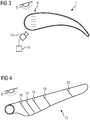
- Fig. 3 shows a cross sectional view of the inventive object of Fig. 2 .
- the camera 13 is positioned under an angle, so that it can record the portions 9 that are stitched into the layers 2 to 6 of fabric.
- the portions 10 and 11 are covered by the portions 9.
- the angle under which the camera 13 records the portions 9 to 11 is arbitrary and preferably adapted to the individual object 1 and test setup.
- Fig. 4 shows a principle drawing of an object 15.
- the object 15 is also a rotor blade for a wind turbine and is built up according to the object 1 described above.
- object 15 comprises the portions 16 to 20 of luminescent material attached to each layer 2 to 6 of the object 15.
- each layer of fabric 2 to 6 of the object 15 comprises a portion 16 to 20 of luminescent material.
- Fig. 4 shows a perspective view of the object 15, where the single attachments of each layer 2 to 6 of fabric are covered by the attachment in the first layer. So only the first portion of luminescent material 16 to 20 is visible in fig. 4.
- Fig. 4 shows therefore, that the portions 16 to 20 of luminescent material can be arranged in every arbitrary way. According to fig.
- the portions 16 to 20 are arranged in arbitrary distances more or less alongside the width the object 15.
- object 15 self-evidently every detail and feature described above with reference to object 1 also applies to object 15 as it only differs from the described object 1 above in the orientation of the portions 16 to 20 of the luminescent material.
Landscapes
- Engineering & Computer Science (AREA)
- Life Sciences & Earth Sciences (AREA)
- Sustainable Development (AREA)
- Sustainable Energy (AREA)
- Chemical & Material Sciences (AREA)
- Combustion & Propulsion (AREA)
- Mechanical Engineering (AREA)
- General Engineering & Computer Science (AREA)
- Wind Motors (AREA)
Description
- The invention relates to an object, in particular a rotor blade for a wind turbine, with a composite construction comprising a plurality of layers of fabric arranged in a matrix material.
- The use of composite constructions comprising a plurality of layers of fabric arranged in a matrix material is well known in the prior art. For example rotor blades for wind turbines are built in such a manner. The fabric is arranged in a cavity according to the desired shape of the rotor blade. A vacuum is applied and subsequently the matrix material is filled into the cavity. Afterwards the rotor blade can be cured, for example by time expired heating.
- Disadvantageously it is not possible or it is difficult to evaluate the overlap of the fabric material or to count the single layers of fabric by visual inspection, as the fabric and the matrix material used are commonly transparent to visible light. An optical monitoring of the rotor blades is therefore often impossible.
- To make sure, that the correct amount of layers is applied or that the layers are applied in the correct shape, respectively, the object has to be cut open. A 100% testing of the produced objects is therefore not possible, as there is no non-destructive examination method available.
-
WO 2012/110041 A1 discloses a system and a method for detecting damage to a wind turbine blade, that uses one or more fluorescent optical fibres comprising a fluorescent material having an excitation wavelength that is selected such that the material fluoresces upon exposure to ambient radiation. It is therefore possible to ascertain a damage to the wind turbine blade as an optical detector detects radiation emitted by the fluorescent optical fibres, as they emit radiation only when cracks or damages, e. g. based on erosion, are present on the said wind turbine blade. - It is therefore an objective of the present invention to provide an object as initially mentioned in such a way that a non-destructive examination of the object is possible.
- This objective is achieved by an object as initially mentioned, whereby several of the plurality of layers are made of fabric comprising at least one portion being equipped with luminescent material.
- The inventive object is composed of a composite construction comprising a plurality of layers of fabric arranged in a matrix material, whereby luminescent material is used to separate at least two layers from each other or to locate the position of one layer which has luminescent material attached thereto or which comprises luminescent material inside the object or inside the matrix material. The present invention pursues the idea, that by using luminescent material, it is possible to count the number of layers in the matrix material, as the fabric and the matrix material is as well transparent to visible light and to light that is able to stimulate the luminescent material. Therefore a light source is used, that is capable of stimulating the luminescent material. When the object is exposed to said light source only the stimulated luminescent material emits radiation and the portions of luminescent material are therefore visible and can be counted, while the rest of the object remains transparent.
- According to an embodiment of the invention each layer of fabric comprises at least one portion comprising luminescent material or having luminescent material attached thereto. In this way the layers of fabric can be counted easily as each layer comprises a portion comprising luminescent material or having luminescent material attached thereto. As the object is exposed to light with adequate wavelength, that is capable to stimulate the luminescent material, the portion of each layer of fabric is made visible. Therefore the single lit up portions of every layer can be counted by visual inspection. Consequently the object does not have to be cut open and can be examined in a non-destructive way.
- According to a further variant of the invention at least one layer comprises at least two portions comprising luminescent material or having luminescent material attached thereto, whereby the portions are arranged in a defined distance over the length of the object. By either applying more than one portion or the at least one layer comprising more than one portion of luminescent material, it is possible to count the layers at different positions along the object. Especially in regard to a rotor blade for a wind turbine the shape and the amount of layers vary with the length of the object. It is therefore preferred to count the amount of those layers of fabric not only at one single position but at more positions for example evenly distributed over the length of the object. It is self-evident, that the positions where the amount of layers of fabric is evaluated can be chosen arbitrarily or for example as defined by the user. Self-evidently it is also possible to define the size and the position of the portions with luminescent material across the object arbitrarily, too. Preferably the portions are arranged close to the edge of the layer in any arbitrary distance, for example 2cm or more, from the edge of the layer and can be arranged at all positions over the width or the length of the layer of fabric. Alternatively the luminescent material, in particular the fluorescent yarn, is preferably as wide as the fabric material or the fabric roll, respectively. It is again ensured, that the orientation of the luminescent material applied to each layer of fabric can be aligned in every arbitrary direction. It is in particular possible to apply the luminescent material alongside the length or the width of each layer of fabric.
- Alternatively it is possible, that the luminescent material is a fluorescent or a phosphorescent or a scintillation material. The material used can be chosen user-defined and in general every material is usable that can be stimulated by an adequate light source in such a way, that luminescent material is made visible preferably with light comprising a wavelength outlying the visual spectrum. The term luminescent material refers generally to every material that is stimulated by light of an adequate wavelength. As the object in particular a rotor blade for a wind turbine is coated or painted or the surface of the object is processed in any other way, the luminescent material inside the object is not visible in the completed object.
- In an embodiment of the present invention the material used is yarn or thread or fibre or texture, in particular fluorescent polyester yarn. The material can therefore be applied in a fine line or any user-defined pattern on each layer of fabric. In particular polyester yarn can be used. Advantageously the polyester yarn is used extensively for example in apparel and home furnishings. It is also well known, that the yarn or thread can be fabricated to be already luminescent. Therefore the luminescent material in form of yarn or thread is widely available and inexpensive.
- In a variant of the present invention the luminescent material is sewn or stitched or woven into at least one layer of fabric. This variant can simplify the production of the inventive object further, as the layers of fabric are each sewn, stitched or woven together in a production process, so that these layers consist of fibres sewn, stitched or woven together. Conveniently only one sewing or stitching has to be applied or exchanged with one luminescent material, for example luminescent yarn or thread. It is therefore possible, to replace for example a single sewing or stitching per layer with yarn or thread of luminescent material. It is further possible to replace the stitching in a defined cycle, e. g. every one hundred, with luminescent material. Advantageously fabric in that way comprises luminescent material or has luminescent material attached thereto with low production effort. Alternatively the luminescent material can be printed onto the layer of fabric. It is for example possible to print a screen print or any other form or texture onto the layer that consists or is made of luminescent material. Hence nearly any pattern or form is applicable to the layers of fabric.
- As already mentioned the object is preferably composed of a plurality of layers of fabric and of matrix material that are transparent for visible light. Therefore for example glass-fibre reinforced plastic can be used with for example polyester resin as matrix material. Since this is the combination of material, that modern rotor blades for wind turbines are made of, the present invention enables a visual inspection, that is non-destructive to ensure, that the correct overlap and/or the correct number of layers of fabric is applied in each object.
- Aside the invention relates to a method of producing an object, in particular a rotor blade for a wind turbine with a composite construction comprising a plurality of layers of fabric being arranged in a matrix material, whereby several of the plurality of layers being made of fabric comprising at least one portion being equipped with the luminescent material. For producing the inventive object at least one portion of at least one of the layers of fabric is provided with luminescent material or luminescent material is attached thereto. Therefore it is possible to make the luminescent material visible, when the object is exposed to a light source with adequate wavelength, capable of stimulating the luminescent material.
- In an embodiment of the inventive method at least one portion of each layer of the object is provided with luminescent material or luminescent material being attached thereto. By pursuing this way every single layer can be made visible when the object is exposed to an adequate light source. This makes the counting of the single layers of fabric simple.
- In a further variant of the inventive method at least two portions of at least one layer are provided with luminescent material or luminescent material being attached thereto, whereby the portions are being arranged in a defined distance over the length of the object. By such an arrangement of the luminescent material it is made possible, that the amount of layers, respectively the overlap of layers of fabric, can be examined over the length of the object in various positions. Self-evidently the positions, where luminescent material is attached or where luminescent material is provided to the at least two portions of the layers is user-defined and arbitrary.
- Preferably the material is sewn or stitched or woven into the layer of fabric. By sewing or stitching or weaving the luminescent material into the layer of fabric the luminescent material can already be arranged on the layer in the production of the fabric material. Therefore the luminescent material can be provided or attached to the fabric material in a simple way.
- Besides a method for analyzing an object, in particular a rotor blade for wind turbine, with a composite construction comprising a plurality of layers of fabric is suggested, whereby several of the plurality of layers are made of fabric comprising at least one portion being equipped with luminescent material and the object being exposed to light with adequate wavelength being able to stimulate the luminescent material.
- In this way it is possible to make the luminescent material visible in the light of the adequate light source. By use of a light source with adequate wavelength, in particular UV-light (ultra violet light) it is possible to stimulate the luminescent material, so that it glows or lights itself. The beholder can therefore easily count the single layers of fabric as the portions with luminescent material are lit up as the rest of the object stays transparent. Besides UV-light every other light source is usable, as long as it emits light of a wavelength that is able to stimulate the luminescent material.
- In a variant of the method for analysing the object it is possible to expose the object to a flashing light source or a continuous light source.
- Preferably at least one picture is recorded via a camera when the object is exposed to light with adequate wavelength. With the picture recorded when the object is exposed to said light source an image of the object with lit up luminescent material can be recorded. Therefore, the object can be saved and evaluated.
- In a further variant of the method for analyzing the object it is possible, that the amount of layers is evaluated via pattern recognition. In particular an image of the camera as described before is taken, when the object is exposed to light with adequate wavelength. Via pattern recognition, for example by a pattern recognition software the single portions of each layer can be evaluated and therefore the amount of layers or the overlap of layers of fabric can be evaluated. Self-evidently every feature of the inventive object, the inventive method for producing the object and the method for analyzing the object can be applied to each other arbitrarily.
- In the following, the invention is described in detail, whereby reference is made to the drawings. The drawings are principal drawings and show:
- Fig. 1
- a perspective view of an inventive object in visible light; and
- Fig. 2
- the perspective view of
Fig. 1 in the light of a light source; - Fig. 3
- a cross sectional view of the inventive object of
Fig. 2 ; and - Fig. 4
- a perspective view of an inventive object in the light of a light source according to an-other embodiment of the invention.
-
Fig. 1 shows a principal drawing of an object 1. The object 1 is a rotor blade for a wind turbine with a composite construction comprising a plurality of layers 2 to 6 of fabric, for example glass fabric. The layers 2 to 6 are arranged in a matrix material 7, for example polyester resin. As the layers 2 to 6 of fabric as well as the matrix material 7 is transparent to visible light. It is not possible to count the layers 2 to 6 by visual inspection. Each of the layers 2 to 6 has aportion 9 comprising luminescent material, in particular fluorescent material being attached thereto. In this embodiment the luminescent material is luminescent polyester yarn that is stitched into the layers 2 to 6 of fabric at theportions Fig. 1 since, as described before, the object 1 is exposed to visible light. Theportions 9 of the respective layers 2 to 6 are arranged in the same position along the object 1, so that evaluation of the amount of layers 2 to 6 can be done effectively. -
Fig. 2 shows a perspective view of the object 1 ofFig. 1 as it is exposed to UV-light emitted by alight source 8 that emits light with a wavelength of for example 360 nm. Thelight source 8 emits the radiation uniformly over the object 1 in particular in the region, where theportions portions distances 12 over the length of the object 1. - As seen in
Fig. 2 theportions light source 8. It is also visible, that the layers 2 to 6 comprise each aportion 9, the layers 2 to 6 comprise aportion 10 in a defineddistance 12 and thelayers third portion 11 also arranged in thedistance 12 between thesecond portion 10 and thethird portion 11. Self-evidently the amount of layer 2 to 6 and the amount ofportions - The object 1 in particular the region of the
portions 9 to 11 is recorded via acamera 13, that is sensitive to the light emitted by the luminescent material as it is stimulated by the light emitted bylight source 8. For example the light emitted by the luminescent material of theportions 9 to 11 is in the blue or yellow part of the visible spectrum. Self-evidently every other colour can be used. It is also possible to use luminescent material that does not emit radiation in the visible spectrum, but for example, in the infrared spectrum. Thecamera 13 has to be adapted to record the light emitted by theportions 9 to 11 of luminescent material. Thecamera 13 is further connected to acentral processor unit 14. Thecentral processor unit 14 is able to run a pattern recognition software, that can evaluate the pictures, that are recorded via thecamera 13. Therefore the amount of layers 2 to 6, respectively theportions camera 13. - In that way a non-destructive examination method for objects that are transparent in visible light and comprise a composite construction comprising a plurality of layers of fabric and matrix material that is also transparent in visible light is made possible. The object 1 does not have to be cut open to count the layers 2 to 6.
-
Fig. 3 shows a cross sectional view of the inventive object ofFig. 2 . Thecamera 13 is positioned under an angle, so that it can record theportions 9 that are stitched into the layers 2 to 6 of fabric. InFig. 3 theportions portions 9. Self-evidently the angle under which thecamera 13 records theportions 9 to 11 is arbitrary and preferably adapted to the individual object 1 and test setup. -
Fig. 4 shows a principle drawing of anobject 15. Theobject 15 is also a rotor blade for a wind turbine and is built up according to the object 1 described above. In contrast to object 1object 15 comprises theportions 16 to 20 of luminescent material attached to each layer 2 to 6 of theobject 15. Of course each layer of fabric 2 to 6 of theobject 15 comprises aportion 16 to 20 of luminescent material.Fig. 4 shows a perspective view of theobject 15, where the single attachments of each layer 2 to 6 of fabric are covered by the attachment in the first layer. So only the first portion ofluminescent material 16 to 20 is visible infig. 4. Fig. 4 shows therefore, that theportions 16 to 20 of luminescent material can be arranged in every arbitrary way. According tofig. 4 theportions 16 to 20 are arranged in arbitrary distances more or less alongside the width theobject 15. Self-evidently every detail and feature described above with reference to object 1 also applies to object 15 as it only differs from the described object 1 above in the orientation of theportions 16 to 20 of the luminescent material. - Although the present invention has been described in detail with reference to the preferred embodiment, the present invention is not limited by the disclosed examples from which the skilled person is able to derive other variations without departing from the scope of the invention.
Claims (13)
- Object (1), in particular a rotor blade for a wind turbine, with a composite construction comprising a plurality of layers (2-6) of fabric arranged in a matrix material (7), characterised in that several of the plurality of layers (2-6) are made of fabric comprising at least one portion (9-11, 16-20) being equipped with luminescent material.
- Object according to claim 1,
characterised in that each layer (2-6) comprises at least one portion (9-11, 16-20) comprising luminescent material or having luminescent material attached thereto. - Object according to claim 1 or 2,
characterised in that at least one layer (2-6) comprises at least two portions (9-11, 16-20) comprising luminescent material or having luminescent material attached thereto, whereby the portions (9-11, 16-20) are arranged in a defined distance (12) over the length of the object (1). - Object according to one of the preceding claims,
characterised in that the luminescent material is fluorescent or phosphorescent material. - Object according to one of the preceding claims,
characterised in that the luminescent material is yarn or thread or fibre or texture, in particular luminescent polyester yarn. - Object according to claim 5,
characterised in that the luminescent material is sewn or stitched or woven into or glued onto the layer (2-6) of fabric. - Object according to one of the claims 1 to 5, characterised in that the luminescent material is printed onto the layer (2-6) of fabric.
- Object according to one of the preceding claims,
characterised in that the fabric material and the matrix material (7) is transparent for visible light. - Object according to one of the preceding claims,
characterised in that the fabric material is glass fabric. - Method of producing an object (1) according to one of the preceding claims, in particular a rotor blade for a wind turbine, with a composite construction comprising a plurality of layers (2-6) of fabric being arranged in a matrix material (7), characterised in that several of the plurality of layers (2-6) are made of fabric comprising at least one portion (9-11, 16-20) being equipped with luminescent material.
- Method according to claim 10,
characterised in that at least one portion (9-11, 16-20) of each layer (2-6) of the object being provided with luminescent material or luminescent material being attached thereto. - Method according to claim 10 or 11,
characterised in that at least two portions (9-11, 16-20) of at least one layer being provided with luminescent material or luminescent material being attached thereto, whereby the portions(9-11, 16-20) being arranged in a defined distance (12) over the length of the object (1). - Method according to one of claims 10 to 12,
characterised in that the luminescent material being sewn or stitched or woven into or glued onto the layer (2-6) of fabric.
Priority Applications (1)
| Application Number | Priority Date | Filing Date | Title |
|---|---|---|---|
| EP15172558.7A EP3106658B1 (en) | 2015-06-17 | 2015-06-17 | Object, in particular a rotor blade for a wind turbine |
Applications Claiming Priority (1)
| Application Number | Priority Date | Filing Date | Title |
|---|---|---|---|
| EP15172558.7A EP3106658B1 (en) | 2015-06-17 | 2015-06-17 | Object, in particular a rotor blade for a wind turbine |
Publications (2)
| Publication Number | Publication Date |
|---|---|
| EP3106658A1 EP3106658A1 (en) | 2016-12-21 |
| EP3106658B1 true EP3106658B1 (en) | 2017-11-29 |
Family
ID=53404455
Family Applications (1)
| Application Number | Title | Priority Date | Filing Date |
|---|---|---|---|
| EP15172558.7A Not-in-force EP3106658B1 (en) | 2015-06-17 | 2015-06-17 | Object, in particular a rotor blade for a wind turbine |
Country Status (1)
| Country | Link |
|---|---|
| EP (1) | EP3106658B1 (en) |
Family Cites Families (3)
| Publication number | Priority date | Publication date | Assignee | Title |
|---|---|---|---|---|
| US8025480B1 (en) * | 2007-06-08 | 2011-09-27 | Weldon W. Alders | Wind turbine blades with avian avoidance surfaces |
| GB2488123A (en) | 2011-02-15 | 2012-08-22 | Vestas Wind Sys As | System and method for detecting damage to a wind turbine blade |
| CN202215428U (en) * | 2011-09-07 | 2012-05-09 | 新疆鑫风麒能源服务股份有限公司 | Vane for wind generating set |
-
2015
- 2015-06-17 EP EP15172558.7A patent/EP3106658B1/en not_active Not-in-force
Non-Patent Citations (1)
| Title |
|---|
| None * |
Also Published As
| Publication number | Publication date |
|---|---|
| EP3106658A1 (en) | 2016-12-21 |
Similar Documents
| Publication | Publication Date | Title |
|---|---|---|
| CN101510454B (en) | Fluorescence vision system | |
| US7489392B2 (en) | Systems and methods for using light to indicate inconsistency locations on a composite structure | |
| CN108732182A (en) | Sheet material check device and inspection system | |
| CN105164519B (en) | Braiding or winding fibrous texture simultaneously check abnormal machine by graphical analysis | |
| US8121386B2 (en) | Secure article, notably a security and/or valuable document | |
| EP2288288B1 (en) | Method and apparatus for illuminating the interior of a medical imaging device | |
| JPS61152494A (en) | Bill into which safety filament is buried and manufacture and inspection method thereof | |
| US11427940B2 (en) | Methods and systems for triggered on-loom fabric inspection | |
| US11500171B2 (en) | Optical fiber ribbon and a method and system of producing the same | |
| KR102204124B1 (en) | XRF marking and XRF mark reading method and system of electronic systems | |
| CN105264328B (en) | For the measuring method that contactlessly optics determines the gage frame of penetration site and attaches troops to a unit | |
| CN110049320A (en) | Camera occlusion detection method, apparatus, electronic equipment and storage medium | |
| CA2879300A1 (en) | Method and system for cutting a preform intended for the production of a turbomachine part | |
| CN106461194B (en) | Assembly for producing light effects with shading function | |
| EP3162285A1 (en) | A sensor element | |
| DE102010037676B4 (en) | Process for monitoring the color homogeneity of the yarn surface and device for carrying it out | |
| DE03739709T1 (en) | DEVICE AND METHOD FOR PROVIDING PRODUCED SPANISH SELECTIVE ONLINE MASS OR VOLUME MEASUREMENTS | |
| JP2016112947A (en) | Method and system for appearance inspection of aircraft | |
| CN109448218A (en) | Not visible characteristic detection device and method, sheet material identification/processing unit, printing inspection apparatus | |
| EP3106658A1 (en) | Object, in particular a rotor blade for a wind turbine | |
| JP2012047582A (en) | Method for measuring surface distribution of near infrared absorption performance and method for manufacturing near infrared absorption filter | |
| CN107576263A (en) | A kind of vision measurement specular light disturbance restraining method | |
| IT201600075862A1 (en) | LABEL IN FABRIC, CONTAINING A UNIQUE INFORMATION AND PROCESS TO REALIZE IT | |
| DE102012015439A1 (en) | Method and device for laminating objects, in particular solar cells | |
| JP5626029B2 (en) | Prepreg defect inspection method, inspection system, and prepreg manufacturing method |
Legal Events
| Date | Code | Title | Description |
|---|---|---|---|
| PUAI | Public reference made under article 153(3) epc to a published international application that has entered the european phase |
Free format text: ORIGINAL CODE: 0009012 |
|
| 17P | Request for examination filed |
Effective date: 20151218 |
|
| AK | Designated contracting states |
Kind code of ref document: A1 Designated state(s): AL AT BE BG CH CY CZ DE DK EE ES FI FR GB GR HR HU IE IS IT LI LT LU LV MC MK MT NL NO PL PT RO RS SE SI SK SM TR |
|
| AX | Request for extension of the european patent |
Extension state: BA ME |
|
| REG | Reference to a national code |
Ref country code: DE Ref legal event code: R079 Ref document number: 602015006280 Country of ref document: DE Free format text: PREVIOUS MAIN CLASS: F03D0013000000 Ipc: F03D0080000000 |
|
| RIC1 | Information provided on ipc code assigned before grant |
Ipc: F03D 80/00 20160101AFI20170510BHEP Ipc: F03D 1/06 20060101ALI20170510BHEP |
|
| GRAP | Despatch of communication of intention to grant a patent |
Free format text: ORIGINAL CODE: EPIDOSNIGR1 |
|
| INTG | Intention to grant announced |
Effective date: 20170620 |
|
| RAP1 | Party data changed (applicant data changed or rights of an application transferred) |
Owner name: SIEMENS AKTIENGESELLSCHAFT |
|
| GRAS | Grant fee paid |
Free format text: ORIGINAL CODE: EPIDOSNIGR3 |
|
| GRAA | (expected) grant |
Free format text: ORIGINAL CODE: 0009210 |
|
| AK | Designated contracting states |
Kind code of ref document: B1 Designated state(s): AL AT BE BG CH CY CZ DE DK EE ES FI FR GB GR HR HU IE IS IT LI LT LU LV MC MK MT NL NO PL PT RO RS SE SI SK SM TR |
|
| REG | Reference to a national code |
Ref country code: CH Ref legal event code: EP |
|
| REG | Reference to a national code |
Ref country code: AT Ref legal event code: REF Ref document number: 950640 Country of ref document: AT Kind code of ref document: T Effective date: 20171215 |
|
| REG | Reference to a national code |
Ref country code: IE Ref legal event code: FG4D |
|
| REG | Reference to a national code |
Ref country code: DE Ref legal event code: R096 Ref document number: 602015006280 Country of ref document: DE |
|
| REG | Reference to a national code |
Ref country code: NL Ref legal event code: MP Effective date: 20171129 |
|
| REG | Reference to a national code |
Ref country code: LT Ref legal event code: MG4D |
|
| REG | Reference to a national code |
Ref country code: AT Ref legal event code: MK05 Ref document number: 950640 Country of ref document: AT Kind code of ref document: T Effective date: 20171129 |
|
| PG25 | Lapsed in a contracting state [announced via postgrant information from national office to epo] |
Ref country code: SE Free format text: LAPSE BECAUSE OF FAILURE TO SUBMIT A TRANSLATION OF THE DESCRIPTION OR TO PAY THE FEE WITHIN THE PRESCRIBED TIME-LIMIT Effective date: 20171129 Ref country code: FI Free format text: LAPSE BECAUSE OF FAILURE TO SUBMIT A TRANSLATION OF THE DESCRIPTION OR TO PAY THE FEE WITHIN THE PRESCRIBED TIME-LIMIT Effective date: 20171129 Ref country code: LT Free format text: LAPSE BECAUSE OF FAILURE TO SUBMIT A TRANSLATION OF THE DESCRIPTION OR TO PAY THE FEE WITHIN THE PRESCRIBED TIME-LIMIT Effective date: 20171129 Ref country code: ES Free format text: LAPSE BECAUSE OF FAILURE TO SUBMIT A TRANSLATION OF THE DESCRIPTION OR TO PAY THE FEE WITHIN THE PRESCRIBED TIME-LIMIT Effective date: 20171129 Ref country code: NO Free format text: LAPSE BECAUSE OF FAILURE TO SUBMIT A TRANSLATION OF THE DESCRIPTION OR TO PAY THE FEE WITHIN THE PRESCRIBED TIME-LIMIT Effective date: 20180228 |
|
| PG25 | Lapsed in a contracting state [announced via postgrant information from national office to epo] |
Ref country code: LV Free format text: LAPSE BECAUSE OF FAILURE TO SUBMIT A TRANSLATION OF THE DESCRIPTION OR TO PAY THE FEE WITHIN THE PRESCRIBED TIME-LIMIT Effective date: 20171129 Ref country code: BG Free format text: LAPSE BECAUSE OF FAILURE TO SUBMIT A TRANSLATION OF THE DESCRIPTION OR TO PAY THE FEE WITHIN THE PRESCRIBED TIME-LIMIT Effective date: 20180228 Ref country code: GR Free format text: LAPSE BECAUSE OF FAILURE TO SUBMIT A TRANSLATION OF THE DESCRIPTION OR TO PAY THE FEE WITHIN THE PRESCRIBED TIME-LIMIT Effective date: 20180301 Ref country code: RS Free format text: LAPSE BECAUSE OF FAILURE TO SUBMIT A TRANSLATION OF THE DESCRIPTION OR TO PAY THE FEE WITHIN THE PRESCRIBED TIME-LIMIT Effective date: 20171129 Ref country code: AT Free format text: LAPSE BECAUSE OF FAILURE TO SUBMIT A TRANSLATION OF THE DESCRIPTION OR TO PAY THE FEE WITHIN THE PRESCRIBED TIME-LIMIT Effective date: 20171129 Ref country code: HR Free format text: LAPSE BECAUSE OF FAILURE TO SUBMIT A TRANSLATION OF THE DESCRIPTION OR TO PAY THE FEE WITHIN THE PRESCRIBED TIME-LIMIT Effective date: 20171129 |
|
| PG25 | Lapsed in a contracting state [announced via postgrant information from national office to epo] |
Ref country code: NL Free format text: LAPSE BECAUSE OF FAILURE TO SUBMIT A TRANSLATION OF THE DESCRIPTION OR TO PAY THE FEE WITHIN THE PRESCRIBED TIME-LIMIT Effective date: 20171129 |
|
| PG25 | Lapsed in a contracting state [announced via postgrant information from national office to epo] |
Ref country code: DK Free format text: LAPSE BECAUSE OF FAILURE TO SUBMIT A TRANSLATION OF THE DESCRIPTION OR TO PAY THE FEE WITHIN THE PRESCRIBED TIME-LIMIT Effective date: 20171129 Ref country code: EE Free format text: LAPSE BECAUSE OF FAILURE TO SUBMIT A TRANSLATION OF THE DESCRIPTION OR TO PAY THE FEE WITHIN THE PRESCRIBED TIME-LIMIT Effective date: 20171129 Ref country code: CY Free format text: LAPSE BECAUSE OF FAILURE TO SUBMIT A TRANSLATION OF THE DESCRIPTION OR TO PAY THE FEE WITHIN THE PRESCRIBED TIME-LIMIT Effective date: 20171129 Ref country code: SK Free format text: LAPSE BECAUSE OF FAILURE TO SUBMIT A TRANSLATION OF THE DESCRIPTION OR TO PAY THE FEE WITHIN THE PRESCRIBED TIME-LIMIT Effective date: 20171129 Ref country code: CZ Free format text: LAPSE BECAUSE OF FAILURE TO SUBMIT A TRANSLATION OF THE DESCRIPTION OR TO PAY THE FEE WITHIN THE PRESCRIBED TIME-LIMIT Effective date: 20171129 |
|
| REG | Reference to a national code |
Ref country code: DE Ref legal event code: R097 Ref document number: 602015006280 Country of ref document: DE |
|
| PG25 | Lapsed in a contracting state [announced via postgrant information from national office to epo] |
Ref country code: IT Free format text: LAPSE BECAUSE OF FAILURE TO SUBMIT A TRANSLATION OF THE DESCRIPTION OR TO PAY THE FEE WITHIN THE PRESCRIBED TIME-LIMIT Effective date: 20171129 Ref country code: SM Free format text: LAPSE BECAUSE OF FAILURE TO SUBMIT A TRANSLATION OF THE DESCRIPTION OR TO PAY THE FEE WITHIN THE PRESCRIBED TIME-LIMIT Effective date: 20171129 Ref country code: PL Free format text: LAPSE BECAUSE OF FAILURE TO SUBMIT A TRANSLATION OF THE DESCRIPTION OR TO PAY THE FEE WITHIN THE PRESCRIBED TIME-LIMIT Effective date: 20171129 |
|
| PLBE | No opposition filed within time limit |
Free format text: ORIGINAL CODE: 0009261 |
|
| STAA | Information on the status of an ep patent application or granted ep patent |
Free format text: STATUS: NO OPPOSITION FILED WITHIN TIME LIMIT |
|
| PGFP | Annual fee paid to national office [announced via postgrant information from national office to epo] |
Ref country code: DE Payment date: 20180820 Year of fee payment: 4 |
|
| 26N | No opposition filed |
Effective date: 20180830 |
|
| PG25 | Lapsed in a contracting state [announced via postgrant information from national office to epo] |
Ref country code: SI Free format text: LAPSE BECAUSE OF FAILURE TO SUBMIT A TRANSLATION OF THE DESCRIPTION OR TO PAY THE FEE WITHIN THE PRESCRIBED TIME-LIMIT Effective date: 20171129 |
|
| REG | Reference to a national code |
Ref country code: CH Ref legal event code: PL |
|
| REG | Reference to a national code |
Ref country code: BE Ref legal event code: MM Effective date: 20180630 |
|
| REG | Reference to a national code |
Ref country code: IE Ref legal event code: MM4A |
|
| PG25 | Lapsed in a contracting state [announced via postgrant information from national office to epo] |
Ref country code: MC Free format text: LAPSE BECAUSE OF FAILURE TO SUBMIT A TRANSLATION OF THE DESCRIPTION OR TO PAY THE FEE WITHIN THE PRESCRIBED TIME-LIMIT Effective date: 20171129 Ref country code: LU Free format text: LAPSE BECAUSE OF NON-PAYMENT OF DUE FEES Effective date: 20180617 |
|
| PG25 | Lapsed in a contracting state [announced via postgrant information from national office to epo] |
Ref country code: FR Free format text: LAPSE BECAUSE OF NON-PAYMENT OF DUE FEES Effective date: 20180630 Ref country code: LI Free format text: LAPSE BECAUSE OF NON-PAYMENT OF DUE FEES Effective date: 20180630 Ref country code: IE Free format text: LAPSE BECAUSE OF NON-PAYMENT OF DUE FEES Effective date: 20180617 Ref country code: CH Free format text: LAPSE BECAUSE OF NON-PAYMENT OF DUE FEES Effective date: 20180630 |
|
| PG25 | Lapsed in a contracting state [announced via postgrant information from national office to epo] |
Ref country code: BE Free format text: LAPSE BECAUSE OF NON-PAYMENT OF DUE FEES Effective date: 20180630 |
|
| REG | Reference to a national code |
Ref country code: DE Ref legal event code: R081 Ref document number: 602015006280 Country of ref document: DE Owner name: SIEMENS GAMESA RENEWABLE ENERGY A/S, DK Free format text: FORMER OWNER: SIEMENS AKTIENGESELLSCHAFT, 80333 MUENCHEN, DE |
|
| REG | Reference to a national code |
Ref country code: DE Ref legal event code: R119 Ref document number: 602015006280 Country of ref document: DE |
|
| PG25 | Lapsed in a contracting state [announced via postgrant information from national office to epo] |
Ref country code: MT Free format text: LAPSE BECAUSE OF NON-PAYMENT OF DUE FEES Effective date: 20180617 |
|
| GBPC | Gb: european patent ceased through non-payment of renewal fee |
Effective date: 20190617 |
|
| PG25 | Lapsed in a contracting state [announced via postgrant information from national office to epo] |
Ref country code: TR Free format text: LAPSE BECAUSE OF FAILURE TO SUBMIT A TRANSLATION OF THE DESCRIPTION OR TO PAY THE FEE WITHIN THE PRESCRIBED TIME-LIMIT Effective date: 20171129 |
|
| PG25 | Lapsed in a contracting state [announced via postgrant information from national office to epo] |
Ref country code: GB Free format text: LAPSE BECAUSE OF NON-PAYMENT OF DUE FEES Effective date: 20190617 Ref country code: DE Free format text: LAPSE BECAUSE OF NON-PAYMENT OF DUE FEES Effective date: 20200101 |
|
| PG25 | Lapsed in a contracting state [announced via postgrant information from national office to epo] |
Ref country code: PT Free format text: LAPSE BECAUSE OF FAILURE TO SUBMIT A TRANSLATION OF THE DESCRIPTION OR TO PAY THE FEE WITHIN THE PRESCRIBED TIME-LIMIT Effective date: 20171129 |
|
| PG25 | Lapsed in a contracting state [announced via postgrant information from national office to epo] |
Ref country code: HU Free format text: LAPSE BECAUSE OF FAILURE TO SUBMIT A TRANSLATION OF THE DESCRIPTION OR TO PAY THE FEE WITHIN THE PRESCRIBED TIME-LIMIT; INVALID AB INITIO Effective date: 20150617 Ref country code: MK Free format text: LAPSE BECAUSE OF NON-PAYMENT OF DUE FEES Effective date: 20171129 Ref country code: RO Free format text: LAPSE BECAUSE OF FAILURE TO SUBMIT A TRANSLATION OF THE DESCRIPTION OR TO PAY THE FEE WITHIN THE PRESCRIBED TIME-LIMIT Effective date: 20171129 |
|
| PG25 | Lapsed in a contracting state [announced via postgrant information from national office to epo] |
Ref country code: AL Free format text: LAPSE BECAUSE OF FAILURE TO SUBMIT A TRANSLATION OF THE DESCRIPTION OR TO PAY THE FEE WITHIN THE PRESCRIBED TIME-LIMIT Effective date: 20171129 Ref country code: IS Free format text: LAPSE BECAUSE OF FAILURE TO SUBMIT A TRANSLATION OF THE DESCRIPTION OR TO PAY THE FEE WITHIN THE PRESCRIBED TIME-LIMIT Effective date: 20180329 |