EP3106636A1 - Blow-by heater - Google Patents
Blow-by heater Download PDFInfo
- Publication number
- EP3106636A1 EP3106636A1 EP15748920.4A EP15748920A EP3106636A1 EP 3106636 A1 EP3106636 A1 EP 3106636A1 EP 15748920 A EP15748920 A EP 15748920A EP 3106636 A1 EP3106636 A1 EP 3106636A1
- Authority
- EP
- European Patent Office
- Prior art keywords
- opening end
- blow
- metal pipe
- face
- vicinity
- Prior art date
- Legal status (The legal status is an assumption and is not a legal conclusion. Google has not performed a legal analysis and makes no representation as to the accuracy of the status listed.)
- Granted
Links
Images

Classifications
-
- F—MECHANICAL ENGINEERING; LIGHTING; HEATING; WEAPONS; BLASTING
- F01—MACHINES OR ENGINES IN GENERAL; ENGINE PLANTS IN GENERAL; STEAM ENGINES
- F01M—LUBRICATING OF MACHINES OR ENGINES IN GENERAL; LUBRICATING INTERNAL COMBUSTION ENGINES; CRANKCASE VENTILATING
- F01M13/00—Crankcase ventilating or breathing
-
- F—MECHANICAL ENGINEERING; LIGHTING; HEATING; WEAPONS; BLASTING
- F01—MACHINES OR ENGINES IN GENERAL; ENGINE PLANTS IN GENERAL; STEAM ENGINES
- F01M—LUBRICATING OF MACHINES OR ENGINES IN GENERAL; LUBRICATING INTERNAL COMBUSTION ENGINES; CRANKCASE VENTILATING
- F01M13/00—Crankcase ventilating or breathing
- F01M13/04—Crankcase ventilating or breathing having means for purifying air before leaving crankcase, e.g. removing oil
-
- F—MECHANICAL ENGINEERING; LIGHTING; HEATING; WEAPONS; BLASTING
- F02—COMBUSTION ENGINES; HOT-GAS OR COMBUSTION-PRODUCT ENGINE PLANTS
- F02M—SUPPLYING COMBUSTION ENGINES IN GENERAL WITH COMBUSTIBLE MIXTURES OR CONSTITUENTS THEREOF
- F02M25/00—Engine-pertinent apparatus for adding non-fuel substances or small quantities of secondary fuel to combustion-air, main fuel or fuel-air mixture
- F02M25/06—Engine-pertinent apparatus for adding non-fuel substances or small quantities of secondary fuel to combustion-air, main fuel or fuel-air mixture adding lubricant vapours
-
- F—MECHANICAL ENGINEERING; LIGHTING; HEATING; WEAPONS; BLASTING
- F02—COMBUSTION ENGINES; HOT-GAS OR COMBUSTION-PRODUCT ENGINE PLANTS
- F02M—SUPPLYING COMBUSTION ENGINES IN GENERAL WITH COMBUSTIBLE MIXTURES OR CONSTITUENTS THEREOF
- F02M35/00—Combustion-air cleaners, air intakes, intake silencers, or induction systems specially adapted for, or arranged on, internal-combustion engines
- F02M35/10—Air intakes; Induction systems
- F02M35/10209—Fluid connections to the air intake system; their arrangement of pipes, valves or the like
- F02M35/10222—Exhaust gas recirculation [EGR]; Positive crankcase ventilation [PCV]; Additional air admission, lubricant or fuel vapour admission
-
- F—MECHANICAL ENGINEERING; LIGHTING; HEATING; WEAPONS; BLASTING
- F01—MACHINES OR ENGINES IN GENERAL; ENGINE PLANTS IN GENERAL; STEAM ENGINES
- F01M—LUBRICATING OF MACHINES OR ENGINES IN GENERAL; LUBRICATING INTERNAL COMBUSTION ENGINES; CRANKCASE VENTILATING
- F01M13/00—Crankcase ventilating or breathing
- F01M13/04—Crankcase ventilating or breathing having means for purifying air before leaving crankcase, e.g. removing oil
- F01M2013/0472—Crankcase ventilating or breathing having means for purifying air before leaving crankcase, e.g. removing oil using heating means
-
- Y—GENERAL TAGGING OF NEW TECHNOLOGICAL DEVELOPMENTS; GENERAL TAGGING OF CROSS-SECTIONAL TECHNOLOGIES SPANNING OVER SEVERAL SECTIONS OF THE IPC; TECHNICAL SUBJECTS COVERED BY FORMER USPC CROSS-REFERENCE ART COLLECTIONS [XRACs] AND DIGESTS
- Y02—TECHNOLOGIES OR APPLICATIONS FOR MITIGATION OR ADAPTATION AGAINST CLIMATE CHANGE
- Y02T—CLIMATE CHANGE MITIGATION TECHNOLOGIES RELATED TO TRANSPORTATION
- Y02T10/00—Road transport of goods or passengers
- Y02T10/10—Internal combustion engine [ICE] based vehicles
- Y02T10/12—Improving ICE efficiencies
Definitions
- the present invention relates to a blow-by heater heating a blow-by gas of an engine, and preventing moisture and the like contained in the blow-by gas from attaching to or freezing at an inner wall portion of a pipe line.
- blow-by gas of the engine is circulated to a gas-intake route of the engine without ejecting the blow-by gas of the engine to the atmosphere. Then, in such a blow-by-gas-circulation pipe line, in order to prevent the moisture and the like contained in the blow-by gas from attaching to or freezing at the inner wall portion of the pipe line, conventionally, there is widely used a blow-by gas heater.
- Fig. 6 is a schematic perspective view showing a conventional blow-by gas heater (corresponding to Fig. 11 of Japanese Patent Application Publication No. 2012-215137 ), and Fig. 7 is a schematic cross-sectional view showing an example wherein the blow-by gas heater in Fig. 6 is provided in a blow-by-gas circulation passage (corresponding to Fig. 9 of the Japanese Patent Application Publication No. 2012-215137 ).
- a metal pipe 55 which becomes a passage of the blow-by gas includes a smooth wall portion 55d and a partially cylindrical wall portion 55e (see Fig. 6 ). Therefore, a cross-sectional opening shape of the metal pipe 55 has a partially circular shape.
- a tip of the smooth wall portion 55d and a tip of the partially cylindrical wall portion 55e form a common opening end face of the metal pipe 55, and a whole tip of the smooth wall portion 55d becomes a last portion 55c of an opening face of the metal pipe 55, and a center portion of the tip of the partially cylindrical wall portion 55e becomes a forefront portion 55b of the opening face of the metal pipe 55 (see Fig. 6 and Fig. 7 ).
- the smooth wall portion 55d is disposed in such a way as to face a heating source 56 which is an electronic ceramic heater through a heating-source attachment pipe 54. In the heating source 56, electric power is supplied through a plug member 57.
- the metal pipe 55 includes a throttle portion 55f formed such that a cross-sectional opening area thereof becomes smaller toward a tip side.
- a protruding portion 55a of the metal pipe 55 is disposed in such a way as to protrude to a gas-intake-passage axis-line side a1 more than to an inner wall face 61d in a connecting pipe 61.
- Moisture or oil of the blow-by gas attached to the metal pipe 55 flows to a tip side thereof (downward) through the protruding portion 55a so as to promote the moisture or oil of the blow-by gas to become a water droplet or an oil droplet.
- the present inventor has diligently considered a shape of an opening end of a blow-by gas heater, and found that the size of the water droplet or the oil droplet (a splash) can be significantly reduced compared to a structure described in Japanese Patent Application Publication No. 2012-215137 .
- An object of the present invention is to provide a blow-by gas heater which can significantly reduce the size of the water droplet or the oil droplet (the splash) of the moisture or oil and the like included in the blow-by gas.
- the present invention is a blow-by heater comprising a tube member allowing a blow-by gas to flow through, and opening in a downstream side, and the tube member is formed such that a thickness of the downstream side decreases toward the opening end.
- a thickness of the tube member allowing the blow-by gas to flow through is formed so as to reduce the thickness toward the opening end, so that in an opening end face of the tube member, an area where the moisture or the oil can remain is small so as to reduce a remaining amount of the moisture or the oil in the opening end face.
- the size of the water droplet or the oil droplet scattered from the opening end face is significantly reduced.
- the tube member is formed such that a thickness of a whole circumferential edge of the downstream side decreases toward the opening end. In that case, the remaining amount of the moisture or the oil in a whole circumference of the opening end face is reduced, so that the size of the water droplet or the oil droplet scattered from the opening end face is significantly reduced in the whole circumference of the opening end face.
- the tube member is formed by a metal pipe including a portion (a throttle portion) wherein a cross-sectional area thereof decreases toward the downstream side.
- a metal pipe can be formed by processing a metal plate formed by press punching into a tube shape.
- the thickness of the downstream side of the metal pipe which is the tube member decreases toward the opening end, for example, in an inner circumferential side in a vicinity of the opening end of the metal pipe, there is formed a slope face portion such that a thickness in the vicinity of the opening end decreases toward the opening end.
- the slope face portion may include a cross-sectional linear surface portion, or a cross-sectional curved surface portion.
- the slope face portion includes the cross-sectional curved surface portion, it is preferable to continue smoothly (without forming a corner portion) from an inner circumferential face of the metal pipe. In that case, the moisture or the oil inside the metal pipe can be smoothly guided further toward the opening end from the inner circumferential face of the metal pipe.
- the slope face portion includes the cross-sectional curved surface portion, in the opening end side, it is preferable to form the corner portion together with an outer circumferential face of the metal pipe. In that case, due to an action of a surface tension in the corner portion, splashing of the moisture or the oil in the corner portion is promoted (it is difficult to remain) so as to reduce the size of the water droplet or the oil droplet further significantly.
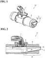
- Fig. 1 is a schematic perspective view showing a blow-by gas heater of one embodiment of the present invention
- Fig. 2 is a schematic cross-sectional view of the blow-by gas heater in Fig. 1
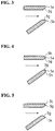
- Fig. 3 is a schematic cross-sectional view showing a shape of a vicinity of an opening end of a metal pipe of the blow-by gas heater in Fig. 1 .
- a metal pipe 5 which becomes a passage of a blow-by gas includes a smooth wall portion 5d and a curved wall portion 5e (see Fig. 1 ).
- a cross-sectional opening shape of the metal pipe 5 has an approximately half-moon shape.
- a whole tip of the smooth wall portion 5d, and a tip of the curved wall portion 5e form a common opening end face 5a of the metal pipe 5 (see Fig. 2 ).
- the smooth wall portion 5d is disposed in such a way as to directly face a heating source 6 which is an electronic ceramic heater. In the heating source 6, there is supplied electric power through a plug member 7.
- the metal pipe 5 includes a throttle portion 5f formed such that a cross-sectional opening area thereof becomes smaller toward a tip side.
- the opening end face 5a of the metal pipe 5 is disposed in such a way as to protrude into a gas-intake passage pipe (not shown in the drawings).
- Moisture or oil of the blow-by gas attached to the metal pipe 5 is guided up to the opening end face 5a so as to become a water droplet or an oil droplet in the opening end face 5a, and scatter into an air flow flowing inside the gas-intake passage pipe (not shown in the drawings).
- a thickness of a downstream side of the metal pipe 5 is formed in such a way as to decrease toward the opening end face 5a.
- a slope face portion 5g in an inner circumferential side in a vicinity of the opening end face 5a of the metal pipe 5, there is formed a slope face portion 5g such that a thickness in the vicinity of the opening end face 5a decreases toward the opening end face 5a.
- the slope face portion 5g includes a cross-sectional linear surface portion.
- a thickness of the metal pipe 5 allowing the blow-by gas to flow through is formed in such a way as to decrease toward the opening end face 5a, so that in the opening end face 5a of the metal pipe 5, an area where the moisture or the oil can remain is small so as to reduce a remaining amount of the moisture or the oil in the opening end face 5a.
- a size of the water droplet or the oil droplet scattered from the opening end face 5a is significantly reduced.
- the slope face portion 5g is formed in a whole circumferential edge on the inner circumferential side in the vicinity of the opening end face 5a of the metal pipe 5 such that a thickness of a whole circumferential edge in the vicinity of the opening end face 5a decreases toward the opening end face 5a.
- the remaining amount of the moisture or the oil in a whole circumference of the opening end face 5a is reduced, so that the size of the water droplet or oil droplet scattered from the opening end face 5a is significantly reduced in the whole circumference of the opening end face 5a.
- Fig. 4 is a schematic cross-sectional view showing another example of the shape of the vicinity of the opening end of the metal pipe 5.
- Fig. 4 which is different from an example shown in Fig. 3 , there are respectively formed the slope face portion 5g and a slope face portion 5h on both of the inner circumferential side and an outer circumferential side in the vicinity of the opening end face 5a of the metal pipe 5.
- the ice block thereof has the small volume so as to suppress the damages and the like of, for example, the turbo impeller.
- an excellent splashing can be obtained provided that an angle is set up to approximately 45 degrees with reference to the opening end face 5a of the metal pipe 5 per an inclination angle of the slope face portion 5g and the slope face portion 5h.
- Fig. 5 is a schematic cross-sectional view further showing another example of the shape of the vicinity of the opening end of the metal pipe 5.
- the slope face portion 5g includes a cross-sectional curved surface portion. More specifically, in the example shown in Fig. 5 , while the slope face portion 5g continues smoothly (without forming a corner portion) from an inner circumferential face of the metal pipe 5, the slope face portion 5g forms a corner portion 5c together with an outer circumferential face of the metal pipe 5.
- the moisture or the oil inside the metal pipe 5 can be smoothly guided further from the inner circumferential face of the metal pipe 5, and due to an action of a surface tension in the corner portion 5c, splashing of the moisture or the oil in the corner portion 5c is promoted (it is difficult to remain) so as to reduce the size of the water droplet or the oil droplet further significantly.
- a tube member is not limited to the tube member formed by processing a metal plate formed by press punching into a tube shape, and may be a tube member made of metal molded by die casting, or made of resin having high thermal conductivity molded by injection molding.
Landscapes
- Engineering & Computer Science (AREA)
- Mechanical Engineering (AREA)
- General Engineering & Computer Science (AREA)
- Chemical & Material Sciences (AREA)
- Combustion & Propulsion (AREA)
- Lubrication Details And Ventilation Of Internal Combustion Engines (AREA)
Abstract
Description
- The present invention relates to a blow-by heater heating a blow-by gas of an engine, and preventing moisture and the like contained in the blow-by gas from attaching to or freezing at an inner wall portion of a pipe line.
- In order to avoid environmental pollution, the blow-by gas of the engine is circulated to a gas-intake route of the engine without ejecting the blow-by gas of the engine to the atmosphere. Then, in such a blow-by-gas-circulation pipe line, in order to prevent the moisture and the like contained in the blow-by gas from attaching to or freezing at the inner wall portion of the pipe line, conventionally, there is widely used a blow-by gas heater.
-
Fig. 6 is a schematic perspective view showing a conventional blow-by gas heater (corresponding to Fig. 11 of Japanese Patent Application Publication No.2012-215137 Fig. 7 is a schematic cross-sectional view showing an example wherein the blow-by gas heater inFig. 6 is provided in a blow-by-gas circulation passage (corresponding to Fig. 9 of the Japanese Patent Application Publication No.2012-215137 - As shown in
Fig. 6 and Fig. 7 , ametal pipe 55 which becomes a passage of the blow-by gas includes asmooth wall portion 55d and a partiallycylindrical wall portion 55e (seeFig. 6 ). Therefore, a cross-sectional opening shape of themetal pipe 55 has a partially circular shape. A tip of thesmooth wall portion 55d and a tip of the partiallycylindrical wall portion 55e form a common opening end face of themetal pipe 55, and a whole tip of thesmooth wall portion 55d becomes alast portion 55c of an opening face of themetal pipe 55, and a center portion of the tip of the partiallycylindrical wall portion 55e becomes aforefront portion 55b of the opening face of the metal pipe 55 (seeFig. 6 and Fig. 7 ). Thesmooth wall portion 55d is disposed in such a way as to face aheating source 56 which is an electronic ceramic heater through a heating-source attachment pipe 54. In theheating source 56, electric power is supplied through aplug member 57. - Also, the
metal pipe 55 includes athrottle portion 55f formed such that a cross-sectional opening area thereof becomes smaller toward a tip side. - As shown in
Fig. 7 , aprotruding portion 55a of themetal pipe 55 is disposed in such a way as to protrude to a gas-intake-passage axis-line side a1 more than to aninner wall face 61d in a connectingpipe 61. Moisture or oil of the blow-by gas attached to themetal pipe 55 flows to a tip side thereof (downward) through the protrudingportion 55a so as to promote the moisture or oil of the blow-by gas to become a water droplet or an oil droplet. - When moisture or oil of a blow-by gas becomes a water droplet or an oil droplet, even in a case wherein the water droplet or the oil droplet freezes and the like thereafter, if an ice block thereof has a small volume, it is possible to suppress damages and the like of, for example, a turbo impeller. The smaller a size of the water droplet or the oil droplet is, the more significant an effect thereof becomes.
- The present inventor has diligently considered a shape of an opening end of a blow-by gas heater, and found that the size of the water droplet or the oil droplet (a splash) can be significantly reduced compared to a structure described in Japanese Patent Application Publication No.
2012-215137 - The present invention is invented based on the aforementioned knowledge. An object of the present invention is to provide a blow-by gas heater which can significantly reduce the size of the water droplet or the oil droplet (the splash) of the moisture or oil and the like included in the blow-by gas.
- The present invention is a blow-by heater comprising a tube member allowing a blow-by gas to flow through, and opening in a downstream side, and the tube member is formed such that a thickness of the downstream side decreases toward the opening end.
- According to the present invention, a thickness of the tube member allowing the blow-by gas to flow through is formed so as to reduce the thickness toward the opening end, so that in an opening end face of the tube member, an area where the moisture or the oil can remain is small so as to reduce a remaining amount of the moisture or the oil in the opening end face. As a result, the size of the water droplet or the oil droplet scattered from the opening end face is significantly reduced. Thereby, even in a case wherein the scattered water droplet or oil droplet freezes and the like thereafter, the ice block thereof has a small volume so as to suppress the damages and the like of, for example, the turbo impeller.
- Preferably, the tube member is formed such that a thickness of a whole circumferential edge of the downstream side decreases toward the opening end. In that case, the remaining amount of the moisture or the oil in a whole circumference of the opening end face is reduced, so that the size of the water droplet or the oil droplet scattered from the opening end face is significantly reduced in the whole circumference of the opening end face.
- Generally, for example, the tube member is formed by a metal pipe including a portion (a throttle portion) wherein a cross-sectional area thereof decreases toward the downstream side. For example, such metal pipe can be formed by processing a metal plate formed by press punching into a tube shape.
- Then, as a specific example wherein the thickness of the downstream side of the metal pipe which is the tube member decreases toward the opening end, for example, in an inner circumferential side in a vicinity of the opening end of the metal pipe, there is formed a slope face portion such that a thickness in the vicinity of the opening end decreases toward the opening end.
- Even in that case, preferably, in a whole circumferential edge on the inner circumferential side in the vicinity of the opening end of the metal pipe, there is formed the slope face portion such that a thickness of a whole circumferential edge in the vicinity of the opening end decreases toward the opening end. In that case, the remaining amount of the moisture or the oil in the whole circumference of the opening end face is reduced, so that the size of the water droplet or the oil droplet scattered from the opening end face is significantly reduced in the whole circumference of the opening end face.
- The slope face portion may include a cross-sectional linear surface portion, or a cross-sectional curved surface portion. In a case wherein the slope face portion includes the cross-sectional curved surface portion, it is preferable to continue smoothly (without forming a corner portion) from an inner circumferential face of the metal pipe. In that case, the moisture or the oil inside the metal pipe can be smoothly guided further toward the opening end from the inner circumferential face of the metal pipe. On the other hand, even in a case wherein the slope face portion includes the cross-sectional curved surface portion, in the opening end side, it is preferable to form the corner portion together with an outer circumferential face of the metal pipe. In that case, due to an action of a surface tension in the corner portion, splashing of the moisture or the oil in the corner portion is promoted (it is difficult to remain) so as to reduce the size of the water droplet or the oil droplet further significantly.
-
-
Fig. 1 is a schematic perspective view showing a blow-by gas heater of one embodiment of the present invention. -
Fig. 2 is a schematic cross-sectional view of the blow-by gas heater inFig. 1 . -
Fig. 3 is a schematic cross-sectional view showing a shape of a vicinity of an opening end of a metal pipe of the blow-by gas heater inFig. 1 . -
Fig. 4 is a schematic cross-sectional view showing another example of the shape of the vicinity of the opening end of the metal pipe. -
Fig. 5 is a schematic cross-sectional view further showing another example of the shape of the vicinity of the opening end of the metal pipe. -
Fig. 6 is a schematic perspective view showing a conventional blow-by gas heater (Fig. 11 of Japanese Patent Application Publication No.2012-215137 -
Fig. 7 is a schematic cross-sectional view showing an example wherein the blow-by gas heater inFig. 6 is provided in a blow-by-gas circulation passage (Fig. 9 of the Japanese Patent Application Publication No.2012-215137 - Hereinafter, with reference to the attached drawings, an embodiment of the present invention will be explained in detail.
-
Fig. 1 is a schematic perspective view showing a blow-by gas heater of one embodiment of the present invention;Fig. 2 is a schematic cross-sectional view of the blow-by gas heater inFig. 1 ; andFig. 3 is a schematic cross-sectional view showing a shape of a vicinity of an opening end of a metal pipe of the blow-by gas heater inFig. 1 . - As shown in
Fig. 1 and Fig. 2 , in a blow-bygas heater 10 of one embodiment of the present invention, ametal pipe 5 which becomes a passage of a blow-by gas includes asmooth wall portion 5d and acurved wall portion 5e (seeFig. 1 ). A cross-sectional opening shape of themetal pipe 5 has an approximately half-moon shape. A whole tip of thesmooth wall portion 5d, and a tip of thecurved wall portion 5e form a commonopening end face 5a of the metal pipe 5 (seeFig. 2 ). Thesmooth wall portion 5d is disposed in such a way as to directly face aheating source 6 which is an electronic ceramic heater. In theheating source 6, there is supplied electric power through aplug member 7. Also, themetal pipe 5 includes athrottle portion 5f formed such that a cross-sectional opening area thereof becomes smaller toward a tip side. - The
opening end face 5a of themetal pipe 5 is disposed in such a way as to protrude into a gas-intake passage pipe (not shown in the drawings). - Moisture or oil of the blow-by gas attached to the
metal pipe 5 is guided up to theopening end face 5a so as to become a water droplet or an oil droplet in theopening end face 5a, and scatter into an air flow flowing inside the gas-intake passage pipe (not shown in the drawings). - In the present embodiment, a thickness of a downstream side of the
metal pipe 5 is formed in such a way as to decrease toward theopening end face 5a. Specifically, as shown inFig. 3 , in an inner circumferential side in a vicinity of theopening end face 5a of themetal pipe 5, there is formed aslope face portion 5g such that a thickness in the vicinity of theopening end face 5a decreases toward theopening end face 5a. As shown inFig. 3 , in the present embodiment, theslope face portion 5g includes a cross-sectional linear surface portion. - According to the present embodiment as described above, a thickness of the
metal pipe 5 allowing the blow-by gas to flow through is formed in such a way as to decrease toward theopening end face 5a, so that in theopening end face 5a of themetal pipe 5, an area where the moisture or the oil can remain is small so as to reduce a remaining amount of the moisture or the oil in theopening end face 5a. As a result, a size of the water droplet or the oil droplet scattered from theopening end face 5a is significantly reduced. Thereby, even in a case wherein the scattered water droplet or oil droplet freezes and the like thereafter, an ice block thereof has a small volume so as to suppress damages and the like of, for example, a turbo impeller. - Incidentally, in the present embodiment, preferably, the
slope face portion 5g is formed in a whole circumferential edge on the inner circumferential side in the vicinity of theopening end face 5a of themetal pipe 5 such that a thickness of a whole circumferential edge in the vicinity of theopening end face 5a decreases toward theopening end face 5a. In that case, the remaining amount of the moisture or the oil in a whole circumference of theopening end face 5a is reduced, so that the size of the water droplet or oil droplet scattered from theopening end face 5a is significantly reduced in the whole circumference of theopening end face 5a. - Next,
Fig. 4 is a schematic cross-sectional view showing another example of the shape of the vicinity of the opening end of themetal pipe 5. In an example shown inFig. 4 which is different from an example shown inFig. 3 , there are respectively formed theslope face portion 5g and aslope face portion 5h on both of the inner circumferential side and an outer circumferential side in the vicinity of theopening end face 5a of themetal pipe 5. - Even in such an example, in the opening
end face 5a of themetal pipe 5, the area where the moisture or the oil can remain is small, and the remaining amount of the moisture or the oil in the openingend face 5a is reduced, so that the size of the water droplet or oil droplet scattered from the openingend face 5a is significantly reduced. Thereby, even in the case wherein the scattered water droplet or oil droplet freezes and the like thereafter, the ice block thereof has the small volume so as to suppress the damages and the like of, for example, the turbo impeller. - According to experiments by the present inventor, an excellent splashing can be obtained provided that an angle is set up to approximately 45 degrees with reference to the opening
end face 5a of themetal pipe 5 per an inclination angle of theslope face portion 5g and theslope face portion 5h. - Next,
Fig. 5 is a schematic cross-sectional view further showing another example of the shape of the vicinity of the opening end of themetal pipe 5. In an example shown inFig. 5 which is different from the example shown inFig. 3 , theslope face portion 5g includes a cross-sectional curved surface portion. More specifically, in the example shown inFig. 5 , while theslope face portion 5g continues smoothly (without forming a corner portion) from an inner circumferential face of themetal pipe 5, theslope face portion 5g forms acorner portion 5c together with an outer circumferential face of themetal pipe 5. - In such an example, the moisture or the oil inside the
metal pipe 5 can be smoothly guided further from the inner circumferential face of themetal pipe 5, and due to an action of a surface tension in thecorner portion 5c, splashing of the moisture or the oil in thecorner portion 5c is promoted (it is difficult to remain) so as to reduce the size of the water droplet or the oil droplet further significantly. - Incidentally, a tube member is not limited to the tube member formed by processing a metal plate formed by press punching into a tube shape, and may be a tube member made of metal molded by die casting, or made of resin having high thermal conductivity molded by injection molding.
- Explanation of Symbols
- 10
- a blow-by gas heater
- 5
- a metal pipe
- 5a
- an opening end face
- 5d
- a smooth wall portion
- 5e
- a curved wall portion
- 5f
- a throttled portion
- 5g
- a slope face portion
- 5h
- a slope face portion
- 6
- a heating source
- 7
- a plug member
- 54
- a heating-source attachment pipe
- 55
- a metal pipe
- 55a
- a protruding portion
- 55b
- a forefront portion
- 55c
- a last portion
- 55d
- a smooth wall portion
- 55e
- a partially cylindrical wall portion
- 55f
- a throttled portion
- 56
- a heating source
- 57
- a plug member
- 61
- a connecting pipe
- 61d
- an inner wall face
Claims (7)
- A blow-by heater, comprising:a tube member allowing a blow-by gas to flow therethrough, and opening in a downstream side,wherein the tube member is formed such that a thickness of the downstream side decreases toward an opening end.
- A blow-by heater according to claim 1, wherein the tube member is formed such that a thickness of a whole circumferential edge of the downstream side decreases toward the opening end.
- A blow-by heater according to claim 1 or 2, wherein the tube member is formed by a metal pipe including a portion wherein a cross-sectional area decreases toward the downstream side, and a slope face portion is formed in an inner circumferential side in a vicinity of the opening end of the metal pipe such that a thickness in the vicinity of the opening end decreases toward the opening end.
- A blow-by heater according to claim 3, wherein a slope face portion is formed in a whole circumferential edge on the inner circumferential side in the vicinity of the opening end of the metal pipe such that a thickness of a whole circumferential edge in the vicinity of the opening end decreases toward the opening end.
- A blow-by heater according to claim 3 or 4, wherein the slope face portion includes a cross-sectional curved surface portion.
- A blow-by heater according to any of claims 3 to 5, wherein the slope face portion forms a corner portion together with an outer circumferential face of the metal pipe.
- A blow-by heater according to any of claims 3 to 6, wherein the metal pipe is formed by processing a metal plate formed by press punching into a tube shape.
Applications Claiming Priority (2)
| Application Number | Priority Date | Filing Date | Title |
|---|---|---|---|
| JP2014024699 | 2014-02-12 | ||
| PCT/JP2015/053776 WO2015122438A1 (en) | 2014-02-12 | 2015-02-12 | Blow-by heater |
Publications (3)
| Publication Number | Publication Date |
|---|---|
| EP3106636A1 true EP3106636A1 (en) | 2016-12-21 |
| EP3106636A4 EP3106636A4 (en) | 2017-11-15 |
| EP3106636B1 EP3106636B1 (en) | 2021-03-10 |
Family
ID=53800180
Family Applications (1)
| Application Number | Title | Priority Date | Filing Date |
|---|---|---|---|
| EP15748920.4A Active EP3106636B1 (en) | 2014-02-12 | 2015-02-12 | Blow-by heater |
Country Status (5)
| Country | Link |
|---|---|
| US (1) | US10066523B2 (en) |
| EP (1) | EP3106636B1 (en) |
| JP (1) | JP6404243B2 (en) |
| CN (1) | CN105980677B (en) |
| WO (1) | WO2015122438A1 (en) |
Families Citing this family (4)
| Publication number | Priority date | Publication date | Assignee | Title |
|---|---|---|---|---|
| JP5913704B1 (en) * | 2015-08-25 | 2016-04-27 | 明生 松本 | Electrode connection for blow-by gas heater and blow-by gas heater using the same |
| JP6538006B2 (en) * | 2016-06-28 | 2019-07-03 | 株式会社クボタ | Blowby gas return structure |
| JP6672189B2 (en) * | 2017-01-13 | 2020-03-25 | ヤンマー株式会社 | Engine equipment |
| JP7139017B2 (en) * | 2017-06-16 | 2022-09-20 | 株式会社イノアックコーポレーション | Air cleaner hose and PCV union |
Family Cites Families (17)
| Publication number | Priority date | Publication date | Assignee | Title |
|---|---|---|---|---|
| JP2975291B2 (en) * | 1995-09-18 | 1999-11-10 | 小島プレス工業株式会社 | Oil trapper for internal combustion engine |
| JP3177461B2 (en) * | 1996-10-01 | 2001-06-18 | 小島プレス工業株式会社 | Oil trapper for internal combustion engine |
| US6062206A (en) * | 1998-03-19 | 2000-05-16 | Phillips & Temro Industries Inc. | PCV heater and method for manufacturing same |
| CN1252491A (en) * | 1998-10-22 | 2000-05-10 | 钟江滢 | Engine energy-saving and purifying silencer |
| JP2002155720A (en) * | 2000-11-20 | 2002-05-31 | Yamaha Motor Co Ltd | Union structure of blow-by gas reduction unit |
| ES2236398T3 (en) * | 2002-06-27 | 2005-07-16 | DAVID & BAADER DBK SPEZIALFABRIK ELEKTRISCHER APPARATE UND HEIZWIDERSTANDE GMBH | HEATING DEVICE FOR A CONDUCT AND CONSTRUCTION PROCEDURE. |
| JP2006063884A (en) | 2004-08-26 | 2006-03-09 | Mazda Motor Corp | Engine blow-by gas recirculation system |
| DE202005012793U1 (en) * | 2005-08-11 | 2006-12-28 | Mann + Hummel Gmbh | Crank case ventilation gas heating device for internal combustion engine of motor vehicle, has spring unit arranged with respect to connector so that mating direction of connector is aligned perpendicular to force direction of spring unit |
| US7537000B2 (en) * | 2006-02-14 | 2009-05-26 | Honda Motor Co., Ltd | Engine with breather apparatus |
| JP2008106637A (en) * | 2006-10-24 | 2008-05-08 | Aisan Ind Co Ltd | Blowby gas passage structure |
| US20080099000A1 (en) * | 2006-10-30 | 2008-05-01 | Aisan Kogyo Kabushiki Kaisha | PCV valve |
| JP2008303833A (en) * | 2007-06-08 | 2008-12-18 | Tokyo Roki Co Ltd | PCV valve |
| JP2009209813A (en) * | 2008-03-05 | 2009-09-17 | Mazda Motor Corp | Blow-by gas recirculation device of engine |
| US8205604B2 (en) * | 2009-11-25 | 2012-06-26 | GM Global Technology Operations LLC | Crankcase vent nozzle for internal combustion engine |
| JP5321852B2 (en) * | 2011-04-01 | 2013-10-23 | マツダ株式会社 | Engine blow-by gas recirculation system |
| JP5886620B2 (en) * | 2011-12-21 | 2016-03-16 | 株式会社ニフコ | Blow-by gas recirculation passage structure |
| JP6135102B2 (en) * | 2012-11-22 | 2017-05-31 | アイシン精機株式会社 | Blow-by gas reduction device |
-
2015
- 2015-02-12 JP JP2015562845A patent/JP6404243B2/en active Active
- 2015-02-12 CN CN201580008054.5A patent/CN105980677B/en active Active
- 2015-02-12 EP EP15748920.4A patent/EP3106636B1/en active Active
- 2015-02-12 US US15/116,684 patent/US10066523B2/en active Active
- 2015-02-12 WO PCT/JP2015/053776 patent/WO2015122438A1/en not_active Ceased
Also Published As
| Publication number | Publication date |
|---|---|
| US20160348549A1 (en) | 2016-12-01 |
| JPWO2015122438A1 (en) | 2017-03-30 |
| EP3106636A4 (en) | 2017-11-15 |
| WO2015122438A1 (en) | 2015-08-20 |
| US10066523B2 (en) | 2018-09-04 |
| EP3106636B1 (en) | 2021-03-10 |
| CN105980677A (en) | 2016-09-28 |
| CN105980677B (en) | 2019-07-05 |
| JP6404243B2 (en) | 2018-10-10 |
Similar Documents
| Publication | Publication Date | Title |
|---|---|---|
| EP3106636B1 (en) | Blow-by heater | |
| EP2159838A3 (en) | Liquid-cooled-type cooling device | |
| EP3098404B1 (en) | Blow-by heater, a resin molded article with a metal insert and a method of molding such a resin molded article with a metal insert | |
| EP3075589A3 (en) | Motorcycle batery arrangement | |
| EP2141329A3 (en) | Impingement cooling device | |
| EP2666964A3 (en) | Gas turbine engine blades with cooling hole trenches | |
| EP1818504A3 (en) | Material having internal cooling passage and method for cooling material having internal cooling passage | |
| KR200461523Y1 (en) | ventilator for molding | |
| EP3382149A3 (en) | Airfoil cooling structure | |
| US11247144B2 (en) | Vented degas bottle for motor vehicle coolant system | |
| ATE547276T1 (en) | SCOOTER | |
| WO2009004851A1 (en) | Oil tank structure | |
| JP2011074862A (en) | Intake manifold | |
| JP2010043771A (en) | Water spray pipe for falling type ice-making machine | |
| US20140204523A1 (en) | Heat dissipation system with air duct | |
| CN104565449B (en) | A kind of composite structure of shower faucet and spool | |
| CN204254891U (en) | A water inlet pipe assembly for an electric water heater | |
| KR102383464B1 (en) | Icing protective structure for blow-by gas | |
| EP2829850A3 (en) | Flowmeter | |
| JP2018084153A (en) | Cooling channel structure | |
| AR086316A1 (en) | REFRIGERATED LAUNCH FOR INJECTION IN METALLURGICAL CONTAINERS | |
| CN204900051U (en) | A pipeline structure for engine | |
| JP2019112957A (en) | Vehicle structure | |
| JP2015165109A (en) | Compressor housing | |
| JP2005212898A (en) | Funnel with fluting |
Legal Events
| Date | Code | Title | Description |
|---|---|---|---|
| STAA | Information on the status of an ep patent application or granted ep patent |
Free format text: STATUS: THE INTERNATIONAL PUBLICATION HAS BEEN MADE |
|
| PUAI | Public reference made under article 153(3) epc to a published international application that has entered the european phase |
Free format text: ORIGINAL CODE: 0009012 |
|
| STAA | Information on the status of an ep patent application or granted ep patent |
Free format text: STATUS: REQUEST FOR EXAMINATION WAS MADE |
|
| 17P | Request for examination filed |
Effective date: 20160902 |
|
| AK | Designated contracting states |
Kind code of ref document: A1 Designated state(s): AL AT BE BG CH CY CZ DE DK EE ES FI FR GB GR HR HU IE IS IT LI LT LU LV MC MK MT NL NO PL PT RO RS SE SI SK SM TR |
|
| AX | Request for extension of the european patent |
Extension state: BA ME |
|
| DAX | Request for extension of the european patent (deleted) | ||
| A4 | Supplementary search report drawn up and despatched |
Effective date: 20171017 |
|
| RIC1 | Information provided on ipc code assigned before grant |
Ipc: F01M 13/00 20060101AFI20171011BHEP Ipc: F02M 35/10 20060101ALI20171011BHEP Ipc: F01M 13/04 20060101ALI20171011BHEP Ipc: F02M 25/06 20160101ALI20171011BHEP |
|
| GRAP | Despatch of communication of intention to grant a patent |
Free format text: ORIGINAL CODE: EPIDOSNIGR1 |
|
| STAA | Information on the status of an ep patent application or granted ep patent |
Free format text: STATUS: GRANT OF PATENT IS INTENDED |
|
| INTG | Intention to grant announced |
Effective date: 20201021 |
|
| RIN1 | Information on inventor provided before grant (corrected) |
Inventor name: OKAZAKI, TSUYOSHI |
|
| GRAS | Grant fee paid |
Free format text: ORIGINAL CODE: EPIDOSNIGR3 |
|
| GRAA | (expected) grant |
Free format text: ORIGINAL CODE: 0009210 |
|
| STAA | Information on the status of an ep patent application or granted ep patent |
Free format text: STATUS: THE PATENT HAS BEEN GRANTED |
|
| AK | Designated contracting states |
Kind code of ref document: B1 Designated state(s): AL AT BE BG CH CY CZ DE DK EE ES FI FR GB GR HR HU IE IS IT LI LT LU LV MC MK MT NL NO PL PT RO RS SE SI SK SM TR |
|
| REG | Reference to a national code |
Ref country code: GB Ref legal event code: FG4D |
|
| REG | Reference to a national code |
Ref country code: AT Ref legal event code: REF Ref document number: 1370025 Country of ref document: AT Kind code of ref document: T Effective date: 20210315 Ref country code: CH Ref legal event code: EP |
|
| REG | Reference to a national code |
Ref country code: IE Ref legal event code: FG4D |
|
| REG | Reference to a national code |
Ref country code: DE Ref legal event code: R096 Ref document number: 602015066662 Country of ref document: DE |
|
| REG | Reference to a national code |
Ref country code: LT Ref legal event code: MG9D |
|
| PG25 | Lapsed in a contracting state [announced via postgrant information from national office to epo] |
Ref country code: NO Free format text: LAPSE BECAUSE OF FAILURE TO SUBMIT A TRANSLATION OF THE DESCRIPTION OR TO PAY THE FEE WITHIN THE PRESCRIBED TIME-LIMIT Effective date: 20210610 Ref country code: BG Free format text: LAPSE BECAUSE OF FAILURE TO SUBMIT A TRANSLATION OF THE DESCRIPTION OR TO PAY THE FEE WITHIN THE PRESCRIBED TIME-LIMIT Effective date: 20210610 Ref country code: HR Free format text: LAPSE BECAUSE OF FAILURE TO SUBMIT A TRANSLATION OF THE DESCRIPTION OR TO PAY THE FEE WITHIN THE PRESCRIBED TIME-LIMIT Effective date: 20210310 Ref country code: GR Free format text: LAPSE BECAUSE OF FAILURE TO SUBMIT A TRANSLATION OF THE DESCRIPTION OR TO PAY THE FEE WITHIN THE PRESCRIBED TIME-LIMIT Effective date: 20210611 Ref country code: FI Free format text: LAPSE BECAUSE OF FAILURE TO SUBMIT A TRANSLATION OF THE DESCRIPTION OR TO PAY THE FEE WITHIN THE PRESCRIBED TIME-LIMIT Effective date: 20210310 Ref country code: LT Free format text: LAPSE BECAUSE OF FAILURE TO SUBMIT A TRANSLATION OF THE DESCRIPTION OR TO PAY THE FEE WITHIN THE PRESCRIBED TIME-LIMIT Effective date: 20210310 |
|
| REG | Reference to a national code |
Ref country code: AT Ref legal event code: MK05 Ref document number: 1370025 Country of ref document: AT Kind code of ref document: T Effective date: 20210310 |
|
| REG | Reference to a national code |
Ref country code: NL Ref legal event code: MP Effective date: 20210310 |
|
| PG25 | Lapsed in a contracting state [announced via postgrant information from national office to epo] |
Ref country code: SE Free format text: LAPSE BECAUSE OF FAILURE TO SUBMIT A TRANSLATION OF THE DESCRIPTION OR TO PAY THE FEE WITHIN THE PRESCRIBED TIME-LIMIT Effective date: 20210310 Ref country code: RS Free format text: LAPSE BECAUSE OF FAILURE TO SUBMIT A TRANSLATION OF THE DESCRIPTION OR TO PAY THE FEE WITHIN THE PRESCRIBED TIME-LIMIT Effective date: 20210310 Ref country code: LV Free format text: LAPSE BECAUSE OF FAILURE TO SUBMIT A TRANSLATION OF THE DESCRIPTION OR TO PAY THE FEE WITHIN THE PRESCRIBED TIME-LIMIT Effective date: 20210310 |
|
| PG25 | Lapsed in a contracting state [announced via postgrant information from national office to epo] |
Ref country code: NL Free format text: LAPSE BECAUSE OF FAILURE TO SUBMIT A TRANSLATION OF THE DESCRIPTION OR TO PAY THE FEE WITHIN THE PRESCRIBED TIME-LIMIT Effective date: 20210310 |
|
| PG25 | Lapsed in a contracting state [announced via postgrant information from national office to epo] |
Ref country code: EE Free format text: LAPSE BECAUSE OF FAILURE TO SUBMIT A TRANSLATION OF THE DESCRIPTION OR TO PAY THE FEE WITHIN THE PRESCRIBED TIME-LIMIT Effective date: 20210310 Ref country code: CZ Free format text: LAPSE BECAUSE OF FAILURE TO SUBMIT A TRANSLATION OF THE DESCRIPTION OR TO PAY THE FEE WITHIN THE PRESCRIBED TIME-LIMIT Effective date: 20210310 Ref country code: SM Free format text: LAPSE BECAUSE OF FAILURE TO SUBMIT A TRANSLATION OF THE DESCRIPTION OR TO PAY THE FEE WITHIN THE PRESCRIBED TIME-LIMIT Effective date: 20210310 Ref country code: AT Free format text: LAPSE BECAUSE OF FAILURE TO SUBMIT A TRANSLATION OF THE DESCRIPTION OR TO PAY THE FEE WITHIN THE PRESCRIBED TIME-LIMIT Effective date: 20210310 |
|
| PG25 | Lapsed in a contracting state [announced via postgrant information from national office to epo] |
Ref country code: IS Free format text: LAPSE BECAUSE OF FAILURE TO SUBMIT A TRANSLATION OF THE DESCRIPTION OR TO PAY THE FEE WITHIN THE PRESCRIBED TIME-LIMIT Effective date: 20210710 Ref country code: PL Free format text: LAPSE BECAUSE OF FAILURE TO SUBMIT A TRANSLATION OF THE DESCRIPTION OR TO PAY THE FEE WITHIN THE PRESCRIBED TIME-LIMIT Effective date: 20210310 Ref country code: PT Free format text: LAPSE BECAUSE OF FAILURE TO SUBMIT A TRANSLATION OF THE DESCRIPTION OR TO PAY THE FEE WITHIN THE PRESCRIBED TIME-LIMIT Effective date: 20210712 Ref country code: ES Free format text: LAPSE BECAUSE OF FAILURE TO SUBMIT A TRANSLATION OF THE DESCRIPTION OR TO PAY THE FEE WITHIN THE PRESCRIBED TIME-LIMIT Effective date: 20210310 Ref country code: SK Free format text: LAPSE BECAUSE OF FAILURE TO SUBMIT A TRANSLATION OF THE DESCRIPTION OR TO PAY THE FEE WITHIN THE PRESCRIBED TIME-LIMIT Effective date: 20210310 Ref country code: RO Free format text: LAPSE BECAUSE OF FAILURE TO SUBMIT A TRANSLATION OF THE DESCRIPTION OR TO PAY THE FEE WITHIN THE PRESCRIBED TIME-LIMIT Effective date: 20210310 |
|
| REG | Reference to a national code |
Ref country code: DE Ref legal event code: R097 Ref document number: 602015066662 Country of ref document: DE |
|
| PLBE | No opposition filed within time limit |
Free format text: ORIGINAL CODE: 0009261 |
|
| STAA | Information on the status of an ep patent application or granted ep patent |
Free format text: STATUS: NO OPPOSITION FILED WITHIN TIME LIMIT |
|
| PG25 | Lapsed in a contracting state [announced via postgrant information from national office to epo] |
Ref country code: AL Free format text: LAPSE BECAUSE OF FAILURE TO SUBMIT A TRANSLATION OF THE DESCRIPTION OR TO PAY THE FEE WITHIN THE PRESCRIBED TIME-LIMIT Effective date: 20210310 Ref country code: DK Free format text: LAPSE BECAUSE OF FAILURE TO SUBMIT A TRANSLATION OF THE DESCRIPTION OR TO PAY THE FEE WITHIN THE PRESCRIBED TIME-LIMIT Effective date: 20210310 |
|
| 26N | No opposition filed |
Effective date: 20211213 |
|
| PG25 | Lapsed in a contracting state [announced via postgrant information from national office to epo] |
Ref country code: SI Free format text: LAPSE BECAUSE OF FAILURE TO SUBMIT A TRANSLATION OF THE DESCRIPTION OR TO PAY THE FEE WITHIN THE PRESCRIBED TIME-LIMIT Effective date: 20210310 |
|
| PG25 | Lapsed in a contracting state [announced via postgrant information from national office to epo] |
Ref country code: IT Free format text: LAPSE BECAUSE OF FAILURE TO SUBMIT A TRANSLATION OF THE DESCRIPTION OR TO PAY THE FEE WITHIN THE PRESCRIBED TIME-LIMIT Effective date: 20210310 |
|
| PG25 | Lapsed in a contracting state [announced via postgrant information from national office to epo] |
Ref country code: IS Free format text: LAPSE BECAUSE OF FAILURE TO SUBMIT A TRANSLATION OF THE DESCRIPTION OR TO PAY THE FEE WITHIN THE PRESCRIBED TIME-LIMIT Effective date: 20210710 |
|
| PG25 | Lapsed in a contracting state [announced via postgrant information from national office to epo] |
Ref country code: MC Free format text: LAPSE BECAUSE OF FAILURE TO SUBMIT A TRANSLATION OF THE DESCRIPTION OR TO PAY THE FEE WITHIN THE PRESCRIBED TIME-LIMIT Effective date: 20210310 |
|
| REG | Reference to a national code |
Ref country code: CH Ref legal event code: PL |
|
| REG | Reference to a national code |
Ref country code: BE Ref legal event code: MM Effective date: 20220228 |
|
| GBPC | Gb: european patent ceased through non-payment of renewal fee |
Effective date: 20220212 |
|
| PG25 | Lapsed in a contracting state [announced via postgrant information from national office to epo] |
Ref country code: LU Free format text: LAPSE BECAUSE OF NON-PAYMENT OF DUE FEES Effective date: 20220212 |
|
| PG25 | Lapsed in a contracting state [announced via postgrant information from national office to epo] |
Ref country code: FR Free format text: LAPSE BECAUSE OF NON-PAYMENT OF DUE FEES Effective date: 20220228 |
|
| PG25 | Lapsed in a contracting state [announced via postgrant information from national office to epo] |
Ref country code: LI Free format text: LAPSE BECAUSE OF NON-PAYMENT OF DUE FEES Effective date: 20220228 Ref country code: IE Free format text: LAPSE BECAUSE OF NON-PAYMENT OF DUE FEES Effective date: 20220212 Ref country code: GB Free format text: LAPSE BECAUSE OF NON-PAYMENT OF DUE FEES Effective date: 20220212 Ref country code: CH Free format text: LAPSE BECAUSE OF NON-PAYMENT OF DUE FEES Effective date: 20220228 |
|
| PG25 | Lapsed in a contracting state [announced via postgrant information from national office to epo] |
Ref country code: BE Free format text: LAPSE BECAUSE OF NON-PAYMENT OF DUE FEES Effective date: 20220228 |
|
| PG25 | Lapsed in a contracting state [announced via postgrant information from national office to epo] |
Ref country code: HU Free format text: LAPSE BECAUSE OF FAILURE TO SUBMIT A TRANSLATION OF THE DESCRIPTION OR TO PAY THE FEE WITHIN THE PRESCRIBED TIME-LIMIT; INVALID AB INITIO Effective date: 20150212 |
|
| PG25 | Lapsed in a contracting state [announced via postgrant information from national office to epo] |
Ref country code: MK Free format text: LAPSE BECAUSE OF FAILURE TO SUBMIT A TRANSLATION OF THE DESCRIPTION OR TO PAY THE FEE WITHIN THE PRESCRIBED TIME-LIMIT Effective date: 20210310 Ref country code: CY Free format text: LAPSE BECAUSE OF FAILURE TO SUBMIT A TRANSLATION OF THE DESCRIPTION OR TO PAY THE FEE WITHIN THE PRESCRIBED TIME-LIMIT Effective date: 20210310 |
|
| PG25 | Lapsed in a contracting state [announced via postgrant information from national office to epo] |
Ref country code: TR Free format text: LAPSE BECAUSE OF FAILURE TO SUBMIT A TRANSLATION OF THE DESCRIPTION OR TO PAY THE FEE WITHIN THE PRESCRIBED TIME-LIMIT Effective date: 20210310 |
|
| PG25 | Lapsed in a contracting state [announced via postgrant information from national office to epo] |
Ref country code: MT Free format text: LAPSE BECAUSE OF FAILURE TO SUBMIT A TRANSLATION OF THE DESCRIPTION OR TO PAY THE FEE WITHIN THE PRESCRIBED TIME-LIMIT Effective date: 20210310 |
|
| PGFP | Annual fee paid to national office [announced via postgrant information from national office to epo] |
Ref country code: DE Payment date: 20251230 Year of fee payment: 12 |