EP3106622A1 - Split line flow path seals - Google Patents
Split line flow path seals Download PDFInfo
- Publication number
- EP3106622A1 EP3106622A1 EP16168849.4A EP16168849A EP3106622A1 EP 3106622 A1 EP3106622 A1 EP 3106622A1 EP 16168849 A EP16168849 A EP 16168849A EP 3106622 A1 EP3106622 A1 EP 3106622A1
- Authority
- EP
- European Patent Office
- Prior art keywords
- rod
- component
- locator
- assembly
- high pressure
- Prior art date
- Legal status (The legal status is an assumption and is not a legal conclusion. Google has not performed a legal analysis and makes no representation as to the accuracy of the status listed.)
- Withdrawn
Links
- 239000000463 material Substances 0.000 claims description 29
- 239000011153 ceramic matrix composite Substances 0.000 claims description 14
- 239000007769 metal material Substances 0.000 claims description 9
- 239000000919 ceramic Substances 0.000 description 9
- 238000007789 sealing Methods 0.000 description 9
- 230000014759 maintenance of location Effects 0.000 description 6
- 239000002184 metal Substances 0.000 description 5
- 238000000034 method Methods 0.000 description 5
- 230000008878 coupling Effects 0.000 description 4
- 238000010168 coupling process Methods 0.000 description 4
- 238000005859 coupling reaction Methods 0.000 description 4
- 230000013011 mating Effects 0.000 description 4
- 238000005219 brazing Methods 0.000 description 3
- 238000002788 crimping Methods 0.000 description 3
- 238000005304 joining Methods 0.000 description 3
- 239000011159 matrix material Substances 0.000 description 3
- 238000003466 welding Methods 0.000 description 3
- 230000006835 compression Effects 0.000 description 2
- 238000007906 compression Methods 0.000 description 2
- 238000005520 cutting process Methods 0.000 description 2
- 238000004519 manufacturing process Methods 0.000 description 2
- 239000007921 spray Substances 0.000 description 2
- 239000000956 alloy Substances 0.000 description 1
- 229910045601 alloy Inorganic materials 0.000 description 1
- 239000011248 coating agent Substances 0.000 description 1
- 238000000576 coating method Methods 0.000 description 1
- 230000008602 contraction Effects 0.000 description 1
- 238000001816 cooling Methods 0.000 description 1
- 238000009434 installation Methods 0.000 description 1
- 238000003754 machining Methods 0.000 description 1
- 238000012986 modification Methods 0.000 description 1
- 230000004048 modification Effects 0.000 description 1
- 230000003647 oxidation Effects 0.000 description 1
- 238000007254 oxidation reaction Methods 0.000 description 1
- 230000001737 promoting effect Effects 0.000 description 1
- 230000008646 thermal stress Effects 0.000 description 1
Images


Classifications
-
- F—MECHANICAL ENGINEERING; LIGHTING; HEATING; WEAPONS; BLASTING
- F01—MACHINES OR ENGINES IN GENERAL; ENGINE PLANTS IN GENERAL; STEAM ENGINES
- F01D—NON-POSITIVE DISPLACEMENT MACHINES OR ENGINES, e.g. STEAM TURBINES
- F01D11/00—Preventing or minimising internal leakage of working-fluid, e.g. between stages
- F01D11/005—Sealing means between non relatively rotating elements
-
- F—MECHANICAL ENGINEERING; LIGHTING; HEATING; WEAPONS; BLASTING
- F01—MACHINES OR ENGINES IN GENERAL; ENGINE PLANTS IN GENERAL; STEAM ENGINES
- F01D—NON-POSITIVE DISPLACEMENT MACHINES OR ENGINES, e.g. STEAM TURBINES
- F01D11/00—Preventing or minimising internal leakage of working-fluid, e.g. between stages
- F01D11/005—Sealing means between non relatively rotating elements
- F01D11/006—Sealing the gap between rotor blades or blades and rotor
- F01D11/008—Sealing the gap between rotor blades or blades and rotor by spacer elements between the blades, e.g. independent interblade platforms
-
- F—MECHANICAL ENGINEERING; LIGHTING; HEATING; WEAPONS; BLASTING
- F01—MACHINES OR ENGINES IN GENERAL; ENGINE PLANTS IN GENERAL; STEAM ENGINES
- F01D—NON-POSITIVE DISPLACEMENT MACHINES OR ENGINES, e.g. STEAM TURBINES
- F01D25/00—Component parts, details, or accessories, not provided for in, or of interest apart from, other groups
- F01D25/24—Casings; Casing parts, e.g. diaphragms, casing fastenings
- F01D25/246—Fastening of diaphragms or stator-rings
-
- F—MECHANICAL ENGINEERING; LIGHTING; HEATING; WEAPONS; BLASTING
- F01—MACHINES OR ENGINES IN GENERAL; ENGINE PLANTS IN GENERAL; STEAM ENGINES
- F01D—NON-POSITIVE DISPLACEMENT MACHINES OR ENGINES, e.g. STEAM TURBINES
- F01D25/00—Component parts, details, or accessories, not provided for in, or of interest apart from, other groups
- F01D25/24—Casings; Casing parts, e.g. diaphragms, casing fastenings
- F01D25/26—Double casings; Measures against temperature strain in casings
-
- F—MECHANICAL ENGINEERING; LIGHTING; HEATING; WEAPONS; BLASTING
- F01—MACHINES OR ENGINES IN GENERAL; ENGINE PLANTS IN GENERAL; STEAM ENGINES
- F01D—NON-POSITIVE DISPLACEMENT MACHINES OR ENGINES, e.g. STEAM TURBINES
- F01D25/00—Component parts, details, or accessories, not provided for in, or of interest apart from, other groups
- F01D25/24—Casings; Casing parts, e.g. diaphragms, casing fastenings
- F01D25/26—Double casings; Measures against temperature strain in casings
- F01D25/265—Vertically split casings; Clamping arrangements therefor
-
- F—MECHANICAL ENGINEERING; LIGHTING; HEATING; WEAPONS; BLASTING
- F01—MACHINES OR ENGINES IN GENERAL; ENGINE PLANTS IN GENERAL; STEAM ENGINES
- F01D—NON-POSITIVE DISPLACEMENT MACHINES OR ENGINES, e.g. STEAM TURBINES
- F01D5/00—Blades; Blade-carrying members; Heating, heat-insulating, cooling or antivibration means on the blades or the members
- F01D5/12—Blades
- F01D5/22—Blade-to-blade connections, e.g. for damping vibrations
- F01D5/225—Blade-to-blade connections, e.g. for damping vibrations by shrouding
-
- F—MECHANICAL ENGINEERING; LIGHTING; HEATING; WEAPONS; BLASTING
- F01—MACHINES OR ENGINES IN GENERAL; ENGINE PLANTS IN GENERAL; STEAM ENGINES
- F01D—NON-POSITIVE DISPLACEMENT MACHINES OR ENGINES, e.g. STEAM TURBINES
- F01D5/00—Blades; Blade-carrying members; Heating, heat-insulating, cooling or antivibration means on the blades or the members
- F01D5/12—Blades
- F01D5/22—Blade-to-blade connections, e.g. for damping vibrations
- F01D5/24—Blade-to-blade connections, e.g. for damping vibrations using wire or the like
-
- F—MECHANICAL ENGINEERING; LIGHTING; HEATING; WEAPONS; BLASTING
- F01—MACHINES OR ENGINES IN GENERAL; ENGINE PLANTS IN GENERAL; STEAM ENGINES
- F01D—NON-POSITIVE DISPLACEMENT MACHINES OR ENGINES, e.g. STEAM TURBINES
- F01D9/00—Stators
- F01D9/02—Nozzles; Nozzle boxes; Stator blades; Guide conduits, e.g. individual nozzles
- F01D9/04—Nozzles; Nozzle boxes; Stator blades; Guide conduits, e.g. individual nozzles forming ring or sector
-
- F—MECHANICAL ENGINEERING; LIGHTING; HEATING; WEAPONS; BLASTING
- F05—INDEXING SCHEMES RELATING TO ENGINES OR PUMPS IN VARIOUS SUBCLASSES OF CLASSES F01-F04
- F05D—INDEXING SCHEME FOR ASPECTS RELATING TO NON-POSITIVE-DISPLACEMENT MACHINES OR ENGINES, GAS-TURBINES OR JET-PROPULSION PLANTS
- F05D2220/00—Application
- F05D2220/30—Application in turbines
- F05D2220/32—Application in turbines in gas turbines
-
- F—MECHANICAL ENGINEERING; LIGHTING; HEATING; WEAPONS; BLASTING
- F05—INDEXING SCHEMES RELATING TO ENGINES OR PUMPS IN VARIOUS SUBCLASSES OF CLASSES F01-F04
- F05D—INDEXING SCHEME FOR ASPECTS RELATING TO NON-POSITIVE-DISPLACEMENT MACHINES OR ENGINES, GAS-TURBINES OR JET-PROPULSION PLANTS
- F05D2240/00—Components
- F05D2240/10—Stators
- F05D2240/11—Shroud seal segments
-
- F—MECHANICAL ENGINEERING; LIGHTING; HEATING; WEAPONS; BLASTING
- F05—INDEXING SCHEMES RELATING TO ENGINES OR PUMPS IN VARIOUS SUBCLASSES OF CLASSES F01-F04
- F05D—INDEXING SCHEME FOR ASPECTS RELATING TO NON-POSITIVE-DISPLACEMENT MACHINES OR ENGINES, GAS-TURBINES OR JET-PROPULSION PLANTS
- F05D2240/00—Components
- F05D2240/55—Seals
-
- F—MECHANICAL ENGINEERING; LIGHTING; HEATING; WEAPONS; BLASTING
- F05—INDEXING SCHEMES RELATING TO ENGINES OR PUMPS IN VARIOUS SUBCLASSES OF CLASSES F01-F04
- F05D—INDEXING SCHEME FOR ASPECTS RELATING TO NON-POSITIVE-DISPLACEMENT MACHINES OR ENGINES, GAS-TURBINES OR JET-PROPULSION PLANTS
- F05D2300/00—Materials; Properties thereof
- F05D2300/60—Properties or characteristics given to material by treatment or manufacturing
- F05D2300/603—Composites; e.g. fibre-reinforced
- F05D2300/6033—Ceramic matrix composites [CMC]
-
- Y—GENERAL TAGGING OF NEW TECHNOLOGICAL DEVELOPMENTS; GENERAL TAGGING OF CROSS-SECTIONAL TECHNOLOGIES SPANNING OVER SEVERAL SECTIONS OF THE IPC; TECHNICAL SUBJECTS COVERED BY FORMER USPC CROSS-REFERENCE ART COLLECTIONS [XRACs] AND DIGESTS
- Y02—TECHNOLOGIES OR APPLICATIONS FOR MITIGATION OR ADAPTATION AGAINST CLIMATE CHANGE
- Y02T—CLIMATE CHANGE MITIGATION TECHNOLOGIES RELATED TO TRANSPORTATION
- Y02T50/00—Aeronautics or air transport
- Y02T50/60—Efficient propulsion technologies, e.g. for aircraft
Definitions
- the present disclosure relates generally to gas turbine engines, and more specifically to seals used in gas turbine engines.
- Gas turbine engines are used to power aircraft, watercraft, power generators, and the like. Adjacent components in a gas turbine engine are often separated by a small gap sometimes called a split line. The small gap allows for variations in manufacturing tolerance of the adjacent components and for expansion/ contraction of the components that occurs during operation of the gas turbine engine.
- the small gaps between adjacent components may be sealed to prevent the leakage of air through the small gaps during operation of the turbine engine. Seals used to block the leakage of air through the small gaps are sometimes designed to account for changes in the dimension of the gap to be closed.
- the present disclosure may comprise one or more of the following features and combinations thereof.
- a gas turbine engine assembly may include a first component, a second component, and a seal assembly.
- the first component and the second component may comprise ceramic matrix materials.
- the first component includes a panel arranged to separate a high pressure zone from a low pressure zone and formed to include a first chamfer surface that extends from a high pressure surface of the first component facing the high pressure zone to a first side surface of the first component.
- the second component includes a panel arranged to separate the high pressure zone from the low pressure zone and formed to include a second chamfer surface that extends from a high pressure surface of the second component facing the high pressure zone to a second side surface of the first component.
- the seal assembly may be arranged in a channel formed by the first chamfer and the second chamfer when the first side surface of the first component is arranged in confronting relation to the second side surface of the second component.
- the seal assembly may include a rod configured to block gasses from passing through the interface of the first side surface included in the first component with the second side surface included in the second component and a rod locator configured to engage the rod to hold the rod in place relative to the first component and the second component.
- the rod of the seal assembly is formed to include a notch into which the rod locator extends.
- the notch extends only partway around the rod included in the seal assembly.
- the notch extends all the way around the rod included in the seal assembly.
- the rod locator is formed to include a cutout that receives a necked-down portion of the rod included in the seal assembly at the notch so that the rod is able to rotate relative to the first component and the second component when used in a gas turbine engine.
- the first chamfered surface has a curved shape as it extends from the high pressure surface of the first component to the first side surface of the first component and the second chamfered surface has a curved shape as it extends from the high pressure surface of the second component to the second side surface of the second component.
- the rod has a generally cylindrical shape.
- the seal assembly includes a bias member configured to push the rod into contact with the first chamfered surface of the first component and the second chamfered surface of the second component.
- the rod locator and the bias member are included in a singular component.
- the singular component comprises a sheet of metallic material having a substantially constant thickness.
- the rod locator is a singular component that comprises a sheet of material having a substantially constant thickness.
- the first component is formed to include a locator slot that receives a portion of the rod locator and the second component is formed to include a locator slot that receives a portion of the rod locator.
- a gas turbine engine assembly may include a first component, a second component, and a rod arranged in a channel formed between the first component and the second component.
- the first component may include a panel arranged to separate a high pressure zone from a low pressure zone when used in a gas turbine engine.
- the second component may include a panel arranged to separate the high pressure zone from the low pressure zone when used in a gas turbine engine.
- the channel may be formed between the first component and the second component that opens toward the high pressure zone when used in a gas turbine engine.
- the assembly may include a rod locator that engages the rod to hold the rod in place relative to the first component and the second component.
- the rod is formed to include a notch into which the rod locator extends.
- the rod locator is formed to include a cutout that receives a necked-down portion of the rod included in the seal assembly at the notch.
- the assembly may include a bias member that engages the rod.
- the assembly may include a rod locator that engages the rod to hold the rod in place relative to the first component and the second component.
- the rod locator and the bias member are included in a singular component.
- the singular component comprises a sheet of metallic material having a substantially constant thickness.
- the assembly may include a rod locator that engages the rod to hold the rod in place relative to the first component and the second component.
- the first component is formed to include a locator slot that receives a portion of the rod locator and the second component is formed to include a locator slot that receives a portion of the rod locator.
- the first component comprises ceramic matrix composite materials and the second component comprises ceramic matrix composite materials.
- a seal assembly 10 is adapted to close a gap 11 between first and second adjacent components 20, 30 in a gas turbine engine assembly 50 as shown in Figs. 1 and 2 .
- the engine assembly 50 separates a high pressure zone HP from a low pressure zone LP within a gas turbine engine.
- the seal assembly 10 is arranged in a channel 40 formed by the adjacent components 20, 30 that opens toward the high pressure zone HP.
- the seal assembly 10 includes a rod 12 illustratively having a round cross sectional profile as shown in Fig. 1 . Gasses in the high pressure zone HP act on the rod 12 of the seal assembly 10 to push the rod 12 into contact with the components 20, 30 so that the rod 12 resists gasses moving through the gap 11 between the first component 20 and the second component 30.
- Each of the components 20, 30 are substantially similar and each includes a panel 22, a first hanger 24, and a second hanger 26 as shown in Figs. 1 and 2 .
- the panel 22 separates the high pressure zone HP from the low pressure zone LP.
- the first and the second hangers 24, 26 are configured to be coupled to structure surrounding the gas turbine engine assembly 50.
- the components 20, 30 are blade track segments made from ceramic matrix materials that may be used with other blade track segments to provide a ring that extends around rotating turbine wheels used in gas turbine engines.
- the components 20, 30 may be made from other materials and/or may be adapted for use as combustor tiles included in the combustor of a gas turbine engine or as heat shields included in other sections of a gas turbine engine.
- the panel 22 of the components 20, 30 is illustratively formed to include a high pressure surface 61 that faces the high pressure zone HP and a low pressure surface 62, opposite the high pressure surface 61, that faces the low pressure zone LP as shown in Fig. 2 .
- the panel 22 is also formed to include a forward side surface 63, an aft side surface 64, a left side surface 65, and a right side surface 66 as shown in Figs. 1 and 2 .
- the panel 22 is formed to include a left chamfer surface 67 that extends at an angle generally from the high pressure surface 61 to the left side surface 65 of the panel 22 and a right chamfer surface 68 that extends at an angle generally from the high pressure surface 61 to the right side surface 66 of the panel 22.
- the chamfer surfaces 67, 68 may be generally flat or barreled (curved).
- the first component 20 and the second component 30 are arranged adjacent to one another so that the right side surface 66 of the first component 20 is in confronting relation with the left side surface 65 of the second component 30 as shown in Fig. 2 .
- the right chamfer surface 68 of the first component 20 then cooperates with the left chamfer surface 67 of the second component 30 to create the channel 40 opening entirely toward the high pressure zone HP that receives the seal assembly 10 as shown in Fig. 3 .
- the chamfer surfaces 67, 68 extend along the corresponding left and right side surfaces 65, 66 from the forward surface 63 to the aft surface 64; accordingly, the channel 40 extends from the forward surface 63 to the aft surface 64 of the panels 22 included in the first and the second components 20, 30.
- the channel 40 is illustratively shaped with straight sides forming a generally triangular space for the seal assembly 10 but may have curved or otherwise shaped sides that provide a space for the seal assembly 10.
- the first and the second hangers 24, 26 are integral with the panels 22 of the first and the second components 20, 30 and are adapted for coupling the panels 22 of the first and the second component 20, 30 with structure surrounding the gas turbine engine assembly 50 as shown in Figs. 1 and 2 .
- the first and the second hangers 24, 26 have a generally L-shape adapted to hang from brackets in a support structure.
- the first and the second hangers may be dovetail shaped, may have pin-receiving holes, or have any other suitable shape for coupling the assembly 50 with other structures.
- first and second hangers 24, 26 each extend over a portion of the channel 40 to provide retention tabs 74, 76 as shown in Fig. 2 .
- the retention tabs 74, 76 provide features that block the seal assembly 10 from movement out of the channel 40 toward the high pressure zone HP (e.g. when the zones HP, LP around the assembly 50 are not pressurized by operation of a gas turbine engine).
- the retention tabs 74, 76 may be independent of the first and the second hangers 24, 26 while still being integrated with the panels 22 of the first and the second components 20, 30.
- the seal assembly 10 illustratively includes the rod 12, a first rod locator 14, and a second rod locator 16 as shown in Fig. 1 .
- the rod 12 is arranged in the channel 40 and is pushed into contact with the first and second components 20, 30 by pressure in the high pressure zone when the engine assembly 50 is used in an operating gas turbine engine to seal the interface 11 between the first and the second components 20, 30.
- the first and the second rod locators 14, 16 are configured to hold the rod 12 in the channel 40 when the engine assembly 50 is not in an operating gas turbine engine such that there is no high pressure zone HP pushing the rod 12 into place.
- the rod 12 is illustratively sized to extend from the forward surface 63 to the aft surface 64 of the panels 22 included in the first and the second components 20, 30 as shown in Figs. 1 and 2 .
- the rod 12 illustratively has a round cross sectional profile but may have an elliptical cross sectional profile or a polygonal cross sectional profile.
- the rod 12 comprises ceramic matrix composite materials but may comprise ceramic monolithic materials, metallic materials, or other suitable materials.
- the rod 12 engages chamfered surfaces 67, 68 of the panels 22 included in the first and the second components 20, 30 to block gasses from passing through the interface 11 between the first and the second components 20, 30 as shown in Fig. 2 .
- the rod 12 is formed to include a first notch 84 and a second notch 86 as shown in Fig. 1 .
- the first notch receives a portion of the first rod locator 14.
- the second notch 86 receives a portion of the second rod locator 16.
- any number of notches may be formed in the rod 12.
- no notches are formed in the rod 12 as different locating features may be included in the components 20, 30 or in the rod locators 14, 16.
- the first notch 84 illustratively extends all the way around the rod 12 as shown in Fig. 1 .
- the first notch receives a portion of the first rod locator 14 so that the rod 12 is axially located by the first rod locator 14 while remaining free to rotate relative to the first rod locator 14.
- the first notch 84 may extend only partway around the rod 12.
- the second notch 86 illustratively extends only partway around the rod 12 as shown in Fig. 1 .
- the second notch 86 receives a portion of the second rod locator 16 so that the rod 12 is axially located by the second rod locator 16 and is blocked from excess rotation relative to the second rod locator 16.
- the second notch 86 and the second rod locator 16 are sized to allow a predetermined amount of rod 12 rotation.
- the second notch 86 may extend all the way around the rod 12.
- the first rod locator 14 is illustratively formed from a material having a generally constant thickness as shown in Fig. 1 .
- the first rod locator 14 extends from the first component 20 and the second component 30 over the channel 40 to block movement of the rod 12 out of the channel 40.
- the first rod locator 14 extends out from a slots 94 formed in the first component 20 and the second component 30.
- the slots 94 are illustratively formed in the first hanger 24 and the panel 22 included in each of the first and the second components 20, 30.
- the first rod locator 14 is formed to include a cutout 15 that receives a necked down portion of the rod 12 at the first notch 84.
- the first rod locator 14 comprises metallic materials but may comprise ceramic-containing materials or other suitable materials.
- the second rod locator 16 is illustratively formed from a material having a generally constant thickness as shown in Fig. 1 .
- the second rod locator 16 extends from the first component 20 and the second component 30 over the channel 40 to block movement of the rod 12 out of the channel 40.
- the second rod locator 16 extends out from a slots 96 formed in the first component 20 and the second component 30.
- the slots 96 are illustratively formed in the second hanger 26 and the panel 22 included in each of the first and the second components 20, 30.
- the second rod locator 16 is generally rectangular and extends through the second notch 86 formed in the rod 12.
- the second rod locator 16 comprises metallic materials but may comprise ceramic-containing materials or other suitable materials.
- the seal assembly 10 may include an optional biasing member 90 as shown in phantom in Figs. 3 and 4 .
- the biasing member 90 may be configured to push the rod 12 into contact with the first chamfered surface 63 of the first component 20 and the second chamfered surface 64 of the second component 30. While two exemplary options for biasing member 90 are shown, any suitable member configured to bias the rod 12 may be included.
- the optional biasing member 90 may be one or more coil springs 91.
- the coil springs 91 may be compression springs that react against supporting structure 99 around the engine assembly 50. In other embodiments, the coil springs 91 may react against the attachment features 24, 26 or other parts of the engine assembly 50.
- the optional biasing member 90 may be one or more bent strip springs 92.
- the bent strip springs 92 may be compression springs that react against supporting structure 99 around the engine assembly 50. In other embodiments, the bent strip springs 92 may react against the attachment features 24, 26 or other parts of the engine assembly 50.
- a second seal assembly 210 is adapted to close a gap 211 between first and second adjacent components 220, 230 in a gas turbine engine assembly 250 as shown in Figs. 5 and 6 .
- the engine assembly 250 separates a high pressure zone HP from a low pressure zone LP within a gas turbine engine.
- the seal assembly 210 is arranged in a channel 240 formed by the adjacent components 220, 230 that opens toward the high pressure zone HP.
- the seal assembly 210 includes a rod 212 illustratively having a round cross sectional profile as shown in Fig. 5 .
- Gasses in the high pressure zone HP act on the rod 212 of the seal assembly 210 to push the rod 212 into contact with the components 220, 230 so that the rod 212 resists gasses moving through the gap 211 between the first component 220 and the second component 230.
- Each of the components 220, 230 are substantially similar and each includes a panel 222, a first hanger 224, and a second hanger 226 as shown in Figs. 5 and 6 .
- the panel2 22 separates the high pressure zone HP from the low pressure zone LP.
- the first and the second hangers 224, 226 are configured to be coupled to structure surrounding the gas turbine engine assembly 250.
- the components 220, 230 are blade track segments made from ceramic matrix materials that may be used with other blade track segments to provide a ring that extends around rotating turbine wheels used in gas turbine engines.
- the components 220, 230 may be made from other materials and/or may be adapted for use as combustor tiles included in the combustor of a gas turbine engine or as heat shields included in other sections of a gas turbine engine.
- the panel 222 of the components 220, 230 is illustratively formed to include a high pressure surface 261 that faces the high pressure zone HP and a low pressure surface 262, opposite the high pressure surface 261, that faces the low pressure zone LP as shown in Fig. 6 .
- the panel 222 is also formed to include a forward side surface 263, an aft side surface 264, a left side surface 265, and a right side surface 266 as shown in Figs. 1 and 2 .
- the panel 222 is formed to include a left chamfer surface 267 that extends at an angle generally from the high pressure surface 261 to the left side surface 265 of the panel 222 and a right chamfer surface 268 that extends at an angle generally from the high pressure surface 261 to the right side surface 266 of the panel 222.
- the chamfer surfaces 226, 268 may be generally flat or barreled (curved).
- the first component 220 and the second component 230 are arranged adjacent to one another so that the right side surface 266 of the first component 220 is in confronting relation with the left side surface 265 of the second component 230 as shown in Fig. 6 .
- the right chamfer surface 268 of the first component 220 then cooperates with the left chamfer surface 267 of the second component 230 to create the channel 240 opening entirely toward the high pressure zone HP that receives the seal assembly 210 as shown in Fig. 6 .
- the chamfer surfaces 267, 268 extend along the corresponding left and right side surfaces 265, 266 from the forward surface 263 to the aft surface 264; accordingly, the channel 240 extends from the forward surface 263 to the aft surface 264 of the panels 222 included in the first and the second components 220, 230.
- the channel 240 is illustratively shaped with straight sides forming a generally triangular space for the seal assembly 210 but may have curved or otherwise shaped sides that provide a space for the seal assembly 210.
- the first and the second hangers 224, 226 are integral with the panels 222 of the first and the second components 220, 230 and are adapted for coupling the panels 222 of the first and the second component 220, 230 with structure surrounding the gas turbine engine assembly 250 as shown in Figs. 5 and 6 .
- the first and the second hangers 224, 226 have a generally L-shape adapted to hang from brackets in a support structure.
- the first and the second hangers may be dovetail shaped, may have pin-receiving holes, or have any other suitable shape for coupling the assembly 250 with other structures.
- the first and second hangers 224, 226 each extend over a portion of the channel 240 to provide retention tabs 274, 276 as shown in Fig. 6 .
- the retention tabs 274, 276 provide features that block the seal assembly 210 from movement out of the channel 240 toward the high pressure zone HP (e.g. when the zones HP, LP around the assembly 250 are not pressurized by operation of a gas turbine engine).
- the retention tabs 274, 276 may be independent of the first and the second hangers 224, 226 while still being integrated with the panels 222 of the first and the second components 220, 230.
- the seal assembly 210 illustratively includes the rod 212, a first rod locator 214, and a second rod locator 216 as shown in Fig. 5 .
- the rod 212 is arranged in the channel 240 and is pushed into contact with the first and second components 220, 230 by pressure in the high pressure zone when the engine assembly 250 is used in an operating gas turbine engine to seal the interface 211 between the first and the second components 220, 230.
- the first and the second rod locators 214, 216 are configured to hold the rod 212 in the channel 240 when the engine assembly 250 is not in an operating gas turbine engine such that there is no high pressure zone HP pushing the rod 212 into place.
- the rod 212 is illustratively sized to extend from the forward surface 263 to the aft surface 264 of the panels 222 included in the first and the second components 220, 230 as shown in Figs. 5 and 6 .
- the rod 212 illustratively has a round cross sectional profile but may have an elliptical cross sectional profile or a polygonal cross sectional profile.
- the rod 212 comprises ceramic matrix composite materials but may comprise ceramic monolithic materials, metallic materials, or other suitable materials.
- the rod 212 engages chamfered surfaces 267, 268 of the panels 222 included in the first and the second components 220, 230 to block gasses from passing through the interface 11 between the first and the second components 220, 230 as shown in Fig. 6 .
- the rod 212 is formed to include a first notch 284 and a second notch 286 as shown in Fig. 1 .
- the first notch receives a portion of the first rod locator 214.
- the second notch 286 receives a portion of the second rod locator 216.
- any number of notches may be formed in the rod 212.
- no notches are formed in the rod 212 as different locating features may be included in the components 220, 230 or in the rod locators 214, 216.
- the first notch 284 and the second notch 286 illustratively extend all the way around the rod 212 as shown in Fig. 5 .
- the first notch 284 receives a portion of the first rod locator 214 so that the rod 212 is axially located by the first rod locator 214 while remaining free to rotate relative to the first rod locator 214.
- the second notch 286 receives a portion of the second rod locator 216 so that the rod 212 is axially located by the second rod locator 216 while remaining free to rotate relative to the second rod locator 216.
- the first and/or the second notch 284, 286 may extend only partway around the rod 212.
- the first rod locator 214 is illustratively formed from a material having a generally constant thickness as shown in Figs.5 and 8 .
- the first rod locator 214 extends from the first component 220 and the second component 230 over the channel 240 to block movement of the rod 212 out of the channel 240.
- the first rod locator 214 extends out from a slots 294 formed in the first component 220 and the second component 230.
- the slots 294 are illustratively formed in the first hanger 224 and the panel 222 included in each of the first and the second components 220, 230.
- the first rod locator 214 is formed to include a cutout 215 that receives a necked down portion of the rod 212 at the first notch 284.
- the first rod locator 214 comprises metallic materials but may comprise ceramic-containing materials or other suitable materials.
- the illustrated first rod locator 214 is shaped to include a first section 214a, a second section 214b, a third section 214c, and a fourth section 214d as shown in Figs. 7 and 8 .
- the first section 214a extends generally in an axial direction in a portion the slot 294 formed in the first hanger 224.
- the second section 214b extends both axially and radially from the first section 214a toward the panel 222 in a portion the slot 294 formed in the first hanger 224.
- the third portion 214c has a U-shaped cross sectional profile and extends generally in a radial direction from the second section 214b into the channel 240 in a portion of the slot 294 formed in the first hanger 224 and the panel 222.
- the cutout 215 is formed in the third portion 214c.
- the fourth portion 214d is illustratively rolled and engages the first hanger 224.
- the fourth portion 214d provides a biasing member 290 as suggested in Fig. 7 .
- the biasing member 290 may be configured to push the rod 212 into contact with the first chamfered surface 263 of the first component 220 and the second chamfered surface 264 of the second component 230.
- the biasing member 290 may have a different shape and may not be integral with the rest of the first rod locator 214.
- the sections 214a-d of the first rod locator 214 extend from one another and are joined at bends within the first rod locator 214 so that the first rod locator 214 is a singular, one-piece, integrated component as shown in Fig. 8 .
- the sections 214a-d of the first rod locator 214 may be fabricated from multiple pieces joined through a welding, brazing, crimping or other joining process.
- the second rod locator 216 is illustratively formed from a material having a generally constant thickness as shown in Figs. 5 and 7 .
- the second rod locator 216 extends from the first component 220 and the second component 230 over the channel 240 to block movement of the rod 212 out of the channel 240.
- the second rod locator 216 extends out from a slots 296 formed in the first component 220 and the second component 230.
- the slots 296 are illustratively formed in the second hanger 226 and the panel 222 included in each of the first and the second components 220, 230.
- the second rod locator 216 is formed to include a cutout 217 that receives a necked down portion of the rod 212 at the second notch 286.
- the second rod locator 216 comprises metallic materials but may comprise ceramic-containing materials or other suitable materials.
- the illustrated second rod locator 216 is shaped to include a first section 216a, a second section 216b, and a third section 216c as shown in Fig. 7 .
- the first section 216a extends generally in an axial direction in a portion the slot 294 formed in the second hanger 226.
- the second section 216c has a U-shaped cross sectional profile and extends generally in a radial direction from the first section 216a into the channel 240 in a portion of the slot 294 formed in the second hanger 226 and the panel 222.
- the cutout 217 is formed in the second portion 216b.
- the third portion 216c is illustratively rolled and engages the second hanger 226.
- the third portion 216c provides a biasing member 290 as suggested in Fig. 7 .
- the biasing member 290 may be configured to push the rod 212 into contact with the first chamfered surface 263 of the first component 220 and the second chamfered surface 264 of the second component 230.
- the biasing member 290 may have a different shape and may not be integral with the rest of the second rod locator 216.
- the sections 216a-c of the second rod locator 216 extend from one another and are joined at bends within the second rod locator 216 so that the second rod locator 216 is a singular, one-piece, integrated component as shown in Figs. 5 and 7 .
- the sections 216a-c of the second rod locator 216 may be fabricated from multiple pieces joined through a welding, brazing, crimping or other joining process.
- the present disclosure provides apparatuses and methods for sealing between components (end walls, blade tracks, etc) where the use of strip seals could create challenges for ceramic matrix composite (CMC) components or other components.
- the illustrative design configuration comprises a cylindrical rod to act as the sealing element between two components. The two components are arranged adjacent to one another around the flow path annulus of the turbine. The seal is pressure activated so the high pressure air forces the sealing rod to contact a surface on each component and restricts the flow of air from the high pressure side of the seal to the low pressure side of the seal.
- the seal surfaces on the adjacent components are arranged along the radially outward edge of the respective components.
- the sealing surfaces are machined chamfer surfaces in the illustrated example.
- the gaps between components may be designed to capture all relative mechanical and thermal motion of the components so the gaps do not open up and allow the sealing rod an escape path. Conversely, the design may allow the gaps to close as well without binding.
- the rod may need to be capable of withstanding high temperatures (>2100degF) and may need to holding its shape for the life of the sealed components.
- the rod may need to be made of a similar material to the CMC.
- An oxide CMC material system may be a candidate since the mechanical loading on the rod is likely to be low and it would be naturally oxidation resistant.
- a SiC CMC material would be capable of handling the highest temperatures, but may need to be designed to minimize the recession of the material. If cooling air leaking around the seal is sufficient to keep the temperature of the rod down, then a high temperature alloy may be sufficient.
- rod locators may be used conjunction with the rod.
- the rod locators can be used to axially locate the rod.
- the rod may include notch (sometimes called groove features) to constrain the rod. Notches may run completely around the circumference of the rod, which will allow the rod to rotate as necessary. Notches may alternatively be cuts that extend some ratio thru the diameter of the rod.
- Machined features in the blade track components of the present disclosure may be simpler to produce than a thin groove that may be used with a strip seal.
- Strip seal grooves can take machining time and special cutting tools may need to be used.
- the opened face features of the chamfer can be made with traditional cutting tools and can be machined very quickly.
- the thin strip seal grooves can also be a source of thermal stresses.
- the angled sealing faces described herein may reduce thermal gradients in the CMC seal segments or endwalls.
- a coating may be applied using Air Plasma Spray (APS).
- APS Air Plasma Spray
- the machined features on each blade track segment have a direct line of sight to all surfaces with ample room for rotating the spray gun. This may be desired since the SiC/SiC CMC component may require all surfaces to be coated to meet life requirements.
- the pressure load transfer from the sealing element to the CMC blade track may be low in the disclosed configurations.
- the rod may be forced onto the angled faces of the seal segments reducing loads normal to the laminate, which reduces the amount of Interlaminar Tensile (ILT) strength capability needed in this area.
- ILT Interlaminar Tensile
- the configurations disclosed herein may allow for a simple installation into the engine ring for blade tracks.
- the seal and the blade track can be installed axially.
- With the disclosed lap joint and rod configuration once the blade tracks are installed axially and locked into position when the blade tracks are constrained.
- the rod is also fully contained.
- the sealing rod allows for relative motion between the two blade tracks (circumferential, axial, radial,tilting). This motion allows for use of rod along flow path and strip seals away from the hot portions of the seal segment.
- Bias members may apply an initial sealing force increasing the effectiveness of the seal at lower pressure ratios.
- a bias member or spring may be fit into the design space of a forward hanger style seal segment.
- a bias member or spring component may be integral with the rod locator as described herein so as to maintain, by means of a mechanical load, rod engagement at all conditions.
- the rod locator may comprise a sheet metal strip seal with an upside down "U” shaped cutout to fit over a circumferential groove in the rod.
- the rod seal locators are shown as being fabricated from one piece with crimps or bends where needed.
- Other one-piece sheet metal forming techniques could also be employed to manufacture the rod locators.
- the rod locators could be fabricated from multiple pieces joined through a welding, brazing, crimping or other joining process.
Landscapes
- Engineering & Computer Science (AREA)
- Mechanical Engineering (AREA)
- General Engineering & Computer Science (AREA)
- Turbine Rotor Nozzle Sealing (AREA)
- Gasket Seals (AREA)
Abstract
Description
- The present disclosure relates generally to gas turbine engines, and more specifically to seals used in gas turbine engines.
- Gas turbine engines are used to power aircraft, watercraft, power generators, and the like. Adjacent components in a gas turbine engine are often separated by a small gap sometimes called a split line. The small gap allows for variations in manufacturing tolerance of the adjacent components and for expansion/ contraction of the components that occurs during operation of the gas turbine engine.
- The small gaps between adjacent components may be sealed to prevent the leakage of air through the small gaps during operation of the turbine engine. Seals used to block the leakage of air through the small gaps are sometimes designed to account for changes in the dimension of the gap to be closed.
- The present disclosure may comprise one or more of the following features and combinations thereof.
- A gas turbine engine assembly may include a first component, a second component, and a seal assembly. The first component and the second component may comprise ceramic matrix materials.
- In illustrative embodiments, the first component includes a panel arranged to separate a high pressure zone from a low pressure zone and formed to include a first chamfer surface that extends from a high pressure surface of the first component facing the high pressure zone to a first side surface of the first component. The second component includes a panel arranged to separate the high pressure zone from the low pressure zone and formed to include a second chamfer surface that extends from a high pressure surface of the second component facing the high pressure zone to a second side surface of the first component. The seal assembly may be arranged in a channel formed by the first chamfer and the second chamfer when the first side surface of the first component is arranged in confronting relation to the second side surface of the second component. The seal assembly may include a rod configured to block gasses from passing through the interface of the first side surface included in the first component with the second side surface included in the second component and a rod locator configured to engage the rod to hold the rod in place relative to the first component and the second component.
- In illustrative embodiments, the rod of the seal assembly is formed to include a notch into which the rod locator extends. In some embodiments, the notch extends only partway around the rod included in the seal assembly. In some embodiments, the notch extends all the way around the rod included in the seal assembly. In some embodiments, the rod locator is formed to include a cutout that receives a necked-down portion of the rod included in the seal assembly at the notch so that the rod is able to rotate relative to the first component and the second component when used in a gas turbine engine.
- In illustrative embodiments, the first chamfered surface has a curved shape as it extends from the high pressure surface of the first component to the first side surface of the first component and the second chamfered surface has a curved shape as it extends from the high pressure surface of the second component to the second side surface of the second component.
- In illustrative embodiments, the rod has a generally cylindrical shape.
- In illustrative embodiments, the seal assembly includes a bias member configured to push the rod into contact with the first chamfered surface of the first component and the second chamfered surface of the second component. In some embodiments, the rod locator and the bias member are included in a singular component. In some embodiments, the singular component comprises a sheet of metallic material having a substantially constant thickness.
- In illustrative embodiments, the rod locator is a singular component that comprises a sheet of material having a substantially constant thickness. In some embodiments, the first component is formed to include a locator slot that receives a portion of the rod locator and the second component is formed to include a locator slot that receives a portion of the rod locator.
- According to another aspect of the present disclosure, a gas turbine engine assembly may include a first component, a second component, and a rod arranged in a channel formed between the first component and the second component.
- In illustrative embodiments, the first component may include a panel arranged to separate a high pressure zone from a low pressure zone when used in a gas turbine engine. The second component may include a panel arranged to separate the high pressure zone from the low pressure zone when used in a gas turbine engine. The channel may be formed between the first component and the second component that opens toward the high pressure zone when used in a gas turbine engine.
- In illustrative embodiments, the assembly may include a rod locator that engages the rod to hold the rod in place relative to the first component and the second component. In some embodiments, the rod is formed to include a notch into which the rod locator extends. In some embodiments, the rod locator is formed to include a cutout that receives a necked-down portion of the rod included in the seal assembly at the notch.
- In illustrative embodiments, the assembly may include a bias member that engages the rod. In some embodiments, the assembly may include a rod locator that engages the rod to hold the rod in place relative to the first component and the second component. In some embodiments, the rod locator and the bias member are included in a singular component. In some embodiments, the singular component comprises a sheet of metallic material having a substantially constant thickness.
- In illustrative embodiments, the assembly may include a rod locator that engages the rod to hold the rod in place relative to the first component and the second component. In some embodiments, the first component is formed to include a locator slot that receives a portion of the rod locator and the second component is formed to include a locator slot that receives a portion of the rod locator.
- In illustrative embodiments, the first component comprises ceramic matrix composite materials and the second component comprises ceramic matrix composite materials.
- These and other features of the present disclosure will become more apparent from the following description of the illustrative embodiments.
-
Fig. 1 is an exploded perspective view of a gas turbine engine assembly including a first blade track component, a second blade track component, and a seal assembly adapted to block gasses from passing through a gap formed at an interface between the first blade track component and the second blade track component showing that the seal assembly includes a rod and a plurality of rod locators; -
Fig. 2 is a perspective view of the gas turbine engine assembly fromFig. 1 assembled to show that the seal assembly is received in a channel formed between the first blade track component and the second blade track component along radially-outwardly facing surfaces of the first blade track component and the second blade track component; -
Fig. 3 is a cross sectional view ofFig. 2 showing coil springs providing an optional biasing member for pushing the rod of the seal assembly into contact with the blade track components; -
Fig. 4 is a cross sectional view ofFig. 2 showing a bent strip spring providing an optional biasing member for pushing the rod of the seal assembly into contact with the blade track components; -
Fig. 5 is an exploded perspective view of a second gas turbine engine assembly including a first blade track component, a second blade track component, and a seal assembly adapted to block gasses from passing through a gap formed at an interface between the first lade track component and the second blade track component showing that the seal assembly includes a rod and a plurality of rod locators; -
Fig. 6 is a perspective view of the gas turbine engine assembly fromFig. 5 assembled to show that the seal assembly is received in a channel formed between the first blade track component and the second blade track component along radially-outwardly facing surfaces of the first blade track component and the second blade track component; -
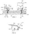
Fig. 7 is a cross sectional view ofFig. 6 showing that the rod locators of the seal assembly are formed to include integrated springs that provide biasing members for pushing the rod into contact with the blade track components; and -
Fig. 8 is an enlarged perspective view of a rod locator included in the seal assembly ofFigs. 5-7 . - For the purposes of promoting an understanding of the principles of the disclosure, reference will now be made to a number of illustrative embodiments shown in the drawings and specific language will be used to describe the same.
- A
seal assembly 10 is adapted to close a gap 11 between first and secondadjacent components turbine engine assembly 50 as shown inFigs. 1 and 2 . Theengine assembly 50 separates a high pressure zone HP from a low pressure zone LP within a gas turbine engine. Theseal assembly 10 is arranged in achannel 40 formed by theadjacent components seal assembly 10 includes arod 12 illustratively having a round cross sectional profile as shown inFig. 1 . Gasses in the high pressure zone HP act on therod 12 of theseal assembly 10 to push therod 12 into contact with thecomponents rod 12 resists gasses moving through the gap 11 between thefirst component 20 and thesecond component 30. - Each of the
components panel 22, afirst hanger 24, and asecond hanger 26 as shown inFigs. 1 and 2 . Thepanel 22 separates the high pressure zone HP from the low pressure zone LP. The first and thesecond hangers turbine engine assembly 50. In the illustrative embodiment, thecomponents components - The
panel 22 of thecomponents high pressure surface 61 that faces the high pressure zone HP and alow pressure surface 62, opposite thehigh pressure surface 61, that faces the low pressure zone LP as shown inFig. 2 . Thepanel 22 is also formed to include aforward side surface 63, anaft side surface 64, aleft side surface 65, and aright side surface 66 as shown inFigs. 1 and 2 . Additionally, in the illustrative embodiment, thepanel 22 is formed to include aleft chamfer surface 67 that extends at an angle generally from thehigh pressure surface 61 to theleft side surface 65 of thepanel 22 and aright chamfer surface 68 that extends at an angle generally from thehigh pressure surface 61 to theright side surface 66 of thepanel 22. Thechamfer surfaces - When assembled, the
first component 20 and thesecond component 30 are arranged adjacent to one another so that theright side surface 66 of thefirst component 20 is in confronting relation with theleft side surface 65 of thesecond component 30 as shown inFig. 2 . Theright chamfer surface 68 of thefirst component 20 then cooperates with theleft chamfer surface 67 of thesecond component 30 to create thechannel 40 opening entirely toward the high pressure zone HP that receives theseal assembly 10 as shown inFig. 3 . Thechamfer surfaces right side surfaces forward surface 63 to theaft surface 64; accordingly, thechannel 40 extends from theforward surface 63 to theaft surface 64 of thepanels 22 included in the first and thesecond components channel 40 is illustratively shaped with straight sides forming a generally triangular space for theseal assembly 10 but may have curved or otherwise shaped sides that provide a space for theseal assembly 10. - The first and the
second hangers panels 22 of the first and thesecond components panels 22 of the first and thesecond component turbine engine assembly 50 as shown inFigs. 1 and 2 . In the illustrative embodiment, the first and thesecond hangers assembly 50 with other structures. - In addition to providing means for attaching the
assembly 50 to other structures, the first andsecond hangers channel 40 to provideretention tabs Fig. 2 . Theretention tabs seal assembly 10 from movement out of thechannel 40 toward the high pressure zone HP (e.g. when the zones HP, LP around theassembly 50 are not pressurized by operation of a gas turbine engine). In some embodiments, theretention tabs second hangers panels 22 of the first and thesecond components - The
seal assembly 10 illustratively includes therod 12, afirst rod locator 14, and asecond rod locator 16 as shown inFig. 1 . Therod 12 is arranged in thechannel 40 and is pushed into contact with the first andsecond components engine assembly 50 is used in an operating gas turbine engine to seal the interface 11 between the first and thesecond components second rod locators rod 12 in thechannel 40 when theengine assembly 50 is not in an operating gas turbine engine such that there is no high pressure zone HP pushing therod 12 into place. - The
rod 12 is illustratively sized to extend from theforward surface 63 to theaft surface 64 of thepanels 22 included in the first and thesecond components Figs. 1 and 2 . Therod 12 illustratively has a round cross sectional profile but may have an elliptical cross sectional profile or a polygonal cross sectional profile. Therod 12 comprises ceramic matrix composite materials but may comprise ceramic monolithic materials, metallic materials, or other suitable materials. - The
rod 12 engages chamfered surfaces 67, 68 of thepanels 22 included in the first and thesecond components second components Fig. 2 . In the illustrative embodiment, therod 12 is formed to include afirst notch 84 and asecond notch 86 as shown inFig. 1 . The first notch receives a portion of thefirst rod locator 14. Thesecond notch 86 receives a portion of thesecond rod locator 16. In other embodiments, any number of notches may be formed in therod 12. In some embodiments, no notches are formed in therod 12 as different locating features may be included in thecomponents rod locators - The
first notch 84 illustratively extends all the way around therod 12 as shown inFig. 1 . The first notch receives a portion of thefirst rod locator 14 so that therod 12 is axially located by thefirst rod locator 14 while remaining free to rotate relative to thefirst rod locator 14. In some embodiments, thefirst notch 84 may extend only partway around therod 12. - The
second notch 86 illustratively extends only partway around therod 12 as shown inFig. 1 . Thesecond notch 86 receives a portion of thesecond rod locator 16 so that therod 12 is axially located by thesecond rod locator 16 and is blocked from excess rotation relative to thesecond rod locator 16. However, thesecond notch 86 and thesecond rod locator 16 are sized to allow a predetermined amount ofrod 12 rotation. In some embodiments, thesecond notch 86 may extend all the way around therod 12. - The
first rod locator 14 is illustratively formed from a material having a generally constant thickness as shown inFig. 1 . Thefirst rod locator 14 extends from thefirst component 20 and thesecond component 30 over thechannel 40 to block movement of therod 12 out of thechannel 40. Thefirst rod locator 14 extends out from aslots 94 formed in thefirst component 20 and thesecond component 30. Theslots 94 are illustratively formed in thefirst hanger 24 and thepanel 22 included in each of the first and thesecond components first rod locator 14 is formed to include acutout 15 that receives a necked down portion of therod 12 at thefirst notch 84. Thefirst rod locator 14 comprises metallic materials but may comprise ceramic-containing materials or other suitable materials. - The
second rod locator 16 is illustratively formed from a material having a generally constant thickness as shown inFig. 1 . Thesecond rod locator 16 extends from thefirst component 20 and thesecond component 30 over thechannel 40 to block movement of therod 12 out of thechannel 40. Thesecond rod locator 16 extends out from aslots 96 formed in thefirst component 20 and thesecond component 30. Theslots 96 are illustratively formed in thesecond hanger 26 and thepanel 22 included in each of the first and thesecond components second rod locator 16 is generally rectangular and extends through thesecond notch 86 formed in therod 12. Thesecond rod locator 16 comprises metallic materials but may comprise ceramic-containing materials or other suitable materials. - In some embodiments, the
seal assembly 10 may include anoptional biasing member 90 as shown in phantom inFigs. 3 and 4 . The biasingmember 90 may be configured to push therod 12 into contact with the first chamferedsurface 63 of thefirst component 20 and the second chamferedsurface 64 of thesecond component 30. While two exemplary options for biasingmember 90 are shown, any suitable member configured to bias therod 12 may be included. - As shown in
Fig. 3 , the optional biasingmember 90 may be one or more coil springs 91. The coil springs 91 may be compression springs that react against supportingstructure 99 around theengine assembly 50. In other embodiments, the coil springs 91 may react against the attachment features 24, 26 or other parts of theengine assembly 50. - As shown in
Fig. 4 , the optional biasingmember 90 may be one or more bent strip springs 92. The bent strip springs 92 may be compression springs that react against supportingstructure 99 around theengine assembly 50. In other embodiments, the bent strip springs 92 may react against the attachment features 24, 26 or other parts of theengine assembly 50. - A
second seal assembly 210 is adapted to close a gap 211 between first and secondadjacent components turbine engine assembly 250 as shown inFigs. 5 and 6 . Theengine assembly 250 separates a high pressure zone HP from a low pressure zone LP within a gas turbine engine. Theseal assembly 210 is arranged in achannel 240 formed by theadjacent components seal assembly 210 includes arod 212 illustratively having a round cross sectional profile as shown inFig. 5 . Gasses in the high pressure zone HP act on therod 212 of theseal assembly 210 to push therod 212 into contact with thecomponents rod 212 resists gasses moving through the gap 211 between thefirst component 220 and thesecond component 230. - Each of the
components panel 222, afirst hanger 224, and asecond hanger 226 as shown inFigs. 5 and 6 . Thepanel2 22 separates the high pressure zone HP from the low pressure zone LP. The first and thesecond hangers turbine engine assembly 250. In the illustrative embodiment, thecomponents components - The
panel 222 of thecomponents high pressure surface 261 that faces the high pressure zone HP and alow pressure surface 262, opposite thehigh pressure surface 261, that faces the low pressure zone LP as shown inFig. 6 . Thepanel 222 is also formed to include aforward side surface 263, anaft side surface 264, aleft side surface 265, and aright side surface 266 as shown inFigs. 1 and 2 . Additionally, in the illustrative embodiment, thepanel 222 is formed to include aleft chamfer surface 267 that extends at an angle generally from thehigh pressure surface 261 to theleft side surface 265 of thepanel 222 and aright chamfer surface 268 that extends at an angle generally from thehigh pressure surface 261 to theright side surface 266 of thepanel 222. The chamfer surfaces 226, 268 may be generally flat or barreled (curved). - When assembled, the
first component 220 and thesecond component 230 are arranged adjacent to one another so that theright side surface 266 of thefirst component 220 is in confronting relation with theleft side surface 265 of thesecond component 230 as shown inFig. 6 . Theright chamfer surface 268 of thefirst component 220 then cooperates with theleft chamfer surface 267 of thesecond component 230 to create thechannel 240 opening entirely toward the high pressure zone HP that receives theseal assembly 210 as shown inFig. 6 . The chamfer surfaces 267, 268 extend along the corresponding left and right side surfaces 265, 266 from theforward surface 263 to theaft surface 264; accordingly, thechannel 240 extends from theforward surface 263 to theaft surface 264 of thepanels 222 included in the first and thesecond components channel 240 is illustratively shaped with straight sides forming a generally triangular space for theseal assembly 210 but may have curved or otherwise shaped sides that provide a space for theseal assembly 210. - The first and the
second hangers panels 222 of the first and thesecond components panels 222 of the first and thesecond component turbine engine assembly 250 as shown inFigs. 5 and 6 . In the illustrative embodiment, the first and thesecond hangers assembly 250 with other structures. - In addition to providing means for attaching the
assembly 250 to other structures, the first andsecond hangers channel 240 to provideretention tabs Fig. 6 . Theretention tabs seal assembly 210 from movement out of thechannel 240 toward the high pressure zone HP (e.g. when the zones HP, LP around theassembly 250 are not pressurized by operation of a gas turbine engine). In some embodiments, theretention tabs second hangers panels 222 of the first and thesecond components - The
seal assembly 210 illustratively includes therod 212, afirst rod locator 214, and asecond rod locator 216 as shown inFig. 5 . Therod 212 is arranged in thechannel 240 and is pushed into contact with the first andsecond components engine assembly 250 is used in an operating gas turbine engine to seal the interface 211 between the first and thesecond components second rod locators rod 212 in thechannel 240 when theengine assembly 250 is not in an operating gas turbine engine such that there is no high pressure zone HP pushing therod 212 into place. - The
rod 212 is illustratively sized to extend from theforward surface 263 to theaft surface 264 of thepanels 222 included in the first and thesecond components Figs. 5 and 6 . Therod 212 illustratively has a round cross sectional profile but may have an elliptical cross sectional profile or a polygonal cross sectional profile. Therod 212 comprises ceramic matrix composite materials but may comprise ceramic monolithic materials, metallic materials, or other suitable materials. - The
rod 212 engages chamferedsurfaces panels 222 included in the first and thesecond components second components Fig. 6 . In the illustrative embodiment, therod 212 is formed to include afirst notch 284 and asecond notch 286 as shown inFig. 1 . The first notch receives a portion of thefirst rod locator 214. Thesecond notch 286 receives a portion of thesecond rod locator 216. In other embodiments, any number of notches may be formed in therod 212. In some embodiments, no notches are formed in therod 212 as different locating features may be included in thecomponents rod locators - The
first notch 284 and thesecond notch 286 illustratively extend all the way around therod 212 as shown inFig. 5 . Thefirst notch 284 receives a portion of thefirst rod locator 214 so that therod 212 is axially located by thefirst rod locator 214 while remaining free to rotate relative to thefirst rod locator 214. Similarly, thesecond notch 286 receives a portion of thesecond rod locator 216 so that therod 212 is axially located by thesecond rod locator 216 while remaining free to rotate relative to thesecond rod locator 216. In some embodiments, the first and/or thesecond notch rod 212. - The
first rod locator 214 is illustratively formed from a material having a generally constant thickness as shown inFigs.5 and8 . Thefirst rod locator 214 extends from thefirst component 220 and thesecond component 230 over thechannel 240 to block movement of therod 212 out of thechannel 240. Thefirst rod locator 214 extends out from aslots 294 formed in thefirst component 220 and thesecond component 230. Theslots 294 are illustratively formed in thefirst hanger 224 and thepanel 222 included in each of the first and thesecond components first rod locator 214 is formed to include acutout 215 that receives a necked down portion of therod 212 at thefirst notch 284. Thefirst rod locator 214 comprises metallic materials but may comprise ceramic-containing materials or other suitable materials. - The illustrated
first rod locator 214 is shaped to include afirst section 214a, asecond section 214b, athird section 214c, and afourth section 214d as shown inFigs. 7 and 8 . Thefirst section 214a extends generally in an axial direction in a portion theslot 294 formed in thefirst hanger 224. Thesecond section 214b extends both axially and radially from thefirst section 214a toward thepanel 222 in a portion theslot 294 formed in thefirst hanger 224. Thethird portion 214c has a U-shaped cross sectional profile and extends generally in a radial direction from thesecond section 214b into thechannel 240 in a portion of theslot 294 formed in thefirst hanger 224 and thepanel 222. Thecutout 215 is formed in thethird portion 214c. Thefourth portion 214d is illustratively rolled and engages thefirst hanger 224. - In the illustrative embodiment, the
fourth portion 214d provides a biasingmember 290 as suggested inFig. 7 . The biasingmember 290 may be configured to push therod 212 into contact with the firstchamfered surface 263 of thefirst component 220 and the secondchamfered surface 264 of thesecond component 230. In other embodiments, the biasingmember 290 may have a different shape and may not be integral with the rest of thefirst rod locator 214. - In the illustrative embodiment, the
sections 214a-d of thefirst rod locator 214 extend from one another and are joined at bends within thefirst rod locator 214 so that thefirst rod locator 214 is a singular, one-piece, integrated component as shown inFig. 8 . In other embodiments, thesections 214a-d of thefirst rod locator 214 may be fabricated from multiple pieces joined through a welding, brazing, crimping or other joining process. - The
second rod locator 216 is illustratively formed from a material having a generally constant thickness as shown inFigs. 5 and7 . Thesecond rod locator 216 extends from thefirst component 220 and thesecond component 230 over thechannel 240 to block movement of therod 212 out of thechannel 240. Thesecond rod locator 216 extends out from aslots 296 formed in thefirst component 220 and thesecond component 230. Theslots 296 are illustratively formed in thesecond hanger 226 and thepanel 222 included in each of the first and thesecond components second rod locator 216 is formed to include acutout 217 that receives a necked down portion of therod 212 at thesecond notch 286. Thesecond rod locator 216 comprises metallic materials but may comprise ceramic-containing materials or other suitable materials. - The illustrated
second rod locator 216 is shaped to include afirst section 216a, asecond section 216b, and athird section 216c as shown inFig. 7 . Thefirst section 216a extends generally in an axial direction in a portion theslot 294 formed in thesecond hanger 226. Thesecond section 216c has a U-shaped cross sectional profile and extends generally in a radial direction from thefirst section 216a into thechannel 240 in a portion of theslot 294 formed in thesecond hanger 226 and thepanel 222. Thecutout 217 is formed in thesecond portion 216b. Thethird portion 216c is illustratively rolled and engages thesecond hanger 226. - In the illustrative embodiment, the
third portion 216c provides a biasingmember 290 as suggested inFig. 7 . The biasingmember 290 may be configured to push therod 212 into contact with the firstchamfered surface 263 of thefirst component 220 and the secondchamfered surface 264 of thesecond component 230. In other embodiments, the biasingmember 290 may have a different shape and may not be integral with the rest of thesecond rod locator 216. - In the illustrative embodiment, the
sections 216a-c of thesecond rod locator 216 extend from one another and are joined at bends within thesecond rod locator 216 so that thesecond rod locator 216 is a singular, one-piece, integrated component as shown inFigs. 5 and7 . In other embodiments, thesections 216a-c of thesecond rod locator 216 may be fabricated from multiple pieces joined through a welding, brazing, crimping or other joining process. - The present disclosure provides apparatuses and methods for sealing between components (end walls, blade tracks, etc) where the use of strip seals could create challenges for ceramic matrix composite (CMC) components or other components. The illustrative design configuration comprises a cylindrical rod to act as the sealing element between two components. The two components are arranged adjacent to one another around the flow path annulus of the turbine. The seal is pressure activated so the high pressure air forces the sealing rod to contact a surface on each component and restricts the flow of air from the high pressure side of the seal to the low pressure side of the seal. The seal surfaces on the adjacent components are arranged along the radially outward edge of the respective components. The sealing surfaces are machined chamfer surfaces in the illustrated example.
- The gaps between components may be designed to capture all relative mechanical and thermal motion of the components so the gaps do not open up and allow the sealing rod an escape path. Conversely, the design may allow the gaps to close as well without binding.
- In illustrative embodiments, the rod may need to be capable of withstanding high temperatures (>2100degF) and may need to holding its shape for the life of the sealed components. The rod may need to be made of a similar material to the CMC. An oxide CMC material system may be a candidate since the mechanical loading on the rod is likely to be low and it would be naturally oxidation resistant. A SiC CMC material would be capable of handling the highest temperatures, but may need to be designed to minimize the recession of the material. If cooling air leaking around the seal is sufficient to keep the temperature of the rod down, then a high temperature alloy may be sufficient.
- In some embodiments, rod locators (sometimes called strip seals) may be used conjunction with the rod. The rod locators can be used to axially locate the rod. In such embodiments, the rod may include notch (sometimes called groove features) to constrain the rod. Notches may run completely around the circumference of the rod, which will allow the rod to rotate as necessary. Notches may alternatively be cuts that extend some ratio thru the diameter of the rod.
- Machined features in the blade track components of the present disclosure may be simpler to produce than a thin groove that may be used with a strip seal. Strip seal grooves can take machining time and special cutting tools may need to be used. The opened face features of the chamfer can be made with traditional cutting tools and can be machined very quickly. The thin strip seal grooves can also be a source of thermal stresses. The angled sealing faces described herein may reduce thermal gradients in the CMC seal segments or endwalls.
- In the included embodiments, a coating may be applied using Air Plasma Spray (APS). The machined features on each blade track segment have a direct line of sight to all surfaces with ample room for rotating the spray gun. This may be desired since the SiC/SiC CMC component may require all surfaces to be coated to meet life requirements.
- The pressure load transfer from the sealing element to the CMC blade track may be low in the disclosed configurations. The rod may be forced onto the angled faces of the seal segments reducing loads normal to the laminate, which reduces the amount of Interlaminar Tensile (ILT) strength capability needed in this area.
- The configurations disclosed herein may allow for a simple installation into the engine ring for blade tracks. The seal and the blade track can be installed axially. With the disclosed lap joint and rod configuration once the blade tracks are installed axially and locked into position when the blade tracks are constrained. The rod is also fully contained.
- The sealing rod allows for relative motion between the two blade tracks (circumferential, axial, radial,tilting). This motion allows for use of rod along flow path and strip seals away from the hot portions of the seal segment.
- Bias members may apply an initial sealing force increasing the effectiveness of the seal at lower pressure ratios. A bias member or spring may be fit into the design space of a forward hanger style seal segment.
- A bias member or spring component may be integral with the rod locator as described herein so as to maintain, by means of a mechanical load, rod engagement at all conditions. In some such embodiments, the rod locator may comprise a sheet metal strip seal with an upside down "U" shaped cutout to fit over a circumferential groove in the rod.
- Other mating geometries are also possible. These could include, but are not limited to no cut-out in the sheet metal seal mating with a chordal slot in the rod, a cut-out in the sheet metal seal mating with a chordal slot in the rod, and/or no cut-out in the sheet metal seal mating with separate forward and aft rod seals.
- In the present disclosure, the rod seal locators are shown as being fabricated from one piece with crimps or bends where needed. Other one-piece sheet metal forming techniques could also be employed to manufacture the rod locators. For example, the rod locators could be fabricated from multiple pieces joined through a welding, brazing, crimping or other joining process.
- While the disclosure has been illustrated and described in detail in the foregoing drawings and description, the same is to be considered as exemplary and not restrictive in character, it being understood that only illustrative embodiments thereof have been shown and described and that all changes and modifications that come within the spirit of the disclosure are desired to be protected.
Claims (11)
- A gas turbine engine assembly (50), the assembly comprising
a first component (20) including a panel (22) arranged to separate a high pressure zone (HP) from a low pressure zone (LP) when used in a gas turbine engine,
a second component (30) including a panel (22) arranged to separate the high pressure zone (HP) from the low pressure zone (LP) when used in a gas turbine engine, and
a rod (12) arranged in a channel (40) formed between the first component (20) and the second component (30) that opens toward the high pressure zone (HP) when used in a gas turbine engine. - The assembly of claim 1, further comprising a rod locator (14, 16) that engages the rod (12) to hold the rod in place relative to the first component (20) and the second component (30), and the rod (12) is formed to include a notch (84, 86) into which the rod locator (14, 16) extends.
- The assembly of claim 2, wherein the notch (86) extends only partway around the rod (12).
- The assembly of claim 2, wherein the rod locator is formed to include a cutout (15) that receives a necked-down portion of the rod (12) included in the seal assembly (10) at the notch (84).
- The assembly of any of claims 1 to 4, further comprising a bias member (90) that engages the rod (12).
- The assembly of claim 5 which comprises a rod locator (214, 126) that engages the rod (212) to hold the rod in place relative to the first component (220) and the second component (230), and the rod locator (214) and the bias member (290) are included in a singular component.
- The assembly of claim 6, wherein the singular component comprises a sheet of metallic material having a substantially constant thickness.
- The assembly of claim 7, further comprising a rod locator (214) that engages the rod (212) to hold the rod in place relative to the first component (220) and the second component (230), and the first component (220) is formed to include a locator slot (294) that receives a portion of the rod locator (214) and the second component is formed to include a locator slot (294) that receives a portion of the rod locator (216).
- The assembly of any preceding claim wherein the first component (20; 220) comprises ceramic matrix composite materials and the second component (30; 230) comprises ceramic matrix composite materials.
- The assembly of any of claims 1 to 9 wherein;
the first component (20) is formed to include a first chamfer surface (67) that extends from a high pressure surface (61) of the first component (20) facing the high pressure zone (HP) to a first side surface (65) of the first component,
the second component (30) formed to include a second chamfer surface (68) that extends from a high pressure surface (61) of the second component (30) facing the high pressure zone (HP) to a second side surface (66) of the first component (20), and
a seal assembly (10) arranged in a channel (40) formed by the first chamfer (67) and the second chamfer (68) when the first side surface (65) of the first component (20) is arranged in confronting relation to the second side surface (66) of the second component (30), the rod (12) forming part of the seal assembly (10) and configured to block gasses from passing through the interface of the first side surface (65) included in the first component (20) with the second side surface (66) included in the second component (30) and a rod locator (14, 16) configured to engage the rod (12) to hold the rod (12) in place relative to the first component (20) and the second component (30). - The assembly of claim 10 wherein the first chamfered surface (67) has a curved shape as it extends from the high pressure surface of the first component to the first side surface (65) of the first component (20) and the second chamfered surface (68) has a curved shape as it extends from the high pressure surface of the second component (30) to the second side surface (66) of the second component.
Applications Claiming Priority (1)
| Application Number | Priority Date | Filing Date | Title |
|---|---|---|---|
| US14/723,909 US9759079B2 (en) | 2015-05-28 | 2015-05-28 | Split line flow path seals |
Publications (1)
| Publication Number | Publication Date |
|---|---|
| EP3106622A1 true EP3106622A1 (en) | 2016-12-21 |
Family
ID=56108469
Family Applications (1)
| Application Number | Title | Priority Date | Filing Date |
|---|---|---|---|
| EP16168849.4A Withdrawn EP3106622A1 (en) | 2015-05-28 | 2016-05-10 | Split line flow path seals |
Country Status (3)
| Country | Link |
|---|---|
| US (2) | US9759079B2 (en) |
| EP (1) | EP3106622A1 (en) |
| CA (1) | CA2929244A1 (en) |
Cited By (3)
| Publication number | Priority date | Publication date | Assignee | Title |
|---|---|---|---|---|
| EP3348792A1 (en) * | 2017-01-11 | 2018-07-18 | Rolls-Royce Corporation | Seal assembly for gas turbine engine components |
| GB2548235B (en) * | 2016-03-01 | 2020-02-26 | Rolls Royce Plc | An intercomponent seal for a gas turbine engine |
| FR3085708A1 (en) * | 2018-09-12 | 2020-03-13 | Safran Helicopter Engines | IMPROVED SEALING DEVICE FOR ROTARY TURBOMACHINE ASSEMBLY |
Families Citing this family (43)
| Publication number | Priority date | Publication date | Assignee | Title |
|---|---|---|---|---|
| JP5717904B1 (en) * | 2014-08-04 | 2015-05-13 | 三菱日立パワーシステムズ株式会社 | Stator blade, gas turbine, split ring, stator blade remodeling method, and split ring remodeling method |
| US9863323B2 (en) * | 2015-02-17 | 2018-01-09 | General Electric Company | Tapered gas turbine segment seals |
| US9759079B2 (en) | 2015-05-28 | 2017-09-12 | Rolls-Royce Corporation | Split line flow path seals |
| US10301955B2 (en) * | 2016-11-29 | 2019-05-28 | Rolls-Royce North American Technologies Inc. | Seal assembly for gas turbine engine components |
| US10746037B2 (en) | 2016-11-30 | 2020-08-18 | Rolls-Royce Corporation | Turbine shroud assembly with tandem seals |
| US10577977B2 (en) | 2017-02-22 | 2020-03-03 | Rolls-Royce Corporation | Turbine shroud with biased retaining ring |
| US10480337B2 (en) | 2017-04-18 | 2019-11-19 | Rolls-Royce North American Technologies Inc. | Turbine shroud assembly with multi-piece seals |
| KR101937586B1 (en) * | 2017-09-12 | 2019-01-10 | 두산중공업 주식회사 | Vane of turbine, turbine and gas turbine comprising it |
| US11802486B2 (en) | 2017-11-13 | 2023-10-31 | General Electric Company | CMC component and fabrication using mechanical joints |
| US10718226B2 (en) | 2017-11-21 | 2020-07-21 | Rolls-Royce Corporation | Ceramic matrix composite component assembly and seal |
| WO2019171495A1 (en) * | 2018-03-07 | 2019-09-12 | 川崎重工業株式会社 | Shroud mounting structure for gas turbine, shroud assembly, and shroud element |
| US20190284947A1 (en) * | 2018-03-14 | 2019-09-19 | General Electric Company | Cmc shroud segment with interlocking mechanical joints and fabrication |
| US10738628B2 (en) * | 2018-05-25 | 2020-08-11 | General Electric Company | Joint for band features on turbine nozzle and fabrication |
| US10794206B2 (en) * | 2018-09-05 | 2020-10-06 | Raytheon Technologies Corporation | CMC BOAS intersegment seal |
| US10934873B2 (en) * | 2018-11-07 | 2021-03-02 | General Electric Company | Sealing system for turbine shroud segments |
| US11131206B2 (en) | 2018-11-08 | 2021-09-28 | Raytheon Technologies Corporation | Substrate edge configurations for ceramic coatings |
| US11326463B2 (en) * | 2019-06-19 | 2022-05-10 | Raytheon Technologies Corporation | BOAS thermal baffle |
| US11073037B2 (en) * | 2019-07-19 | 2021-07-27 | Raytheon Technologies Corporation | CMC BOAS arrangement |
| US11248482B2 (en) | 2019-07-19 | 2022-02-15 | Raytheon Technologies Corporation | CMC BOAS arrangement |
| US11105214B2 (en) | 2019-07-19 | 2021-08-31 | Raytheon Technologies Corporation | CMC BOAS arrangement |
| US11073038B2 (en) * | 2019-07-19 | 2021-07-27 | Raytheon Technologies Corporation | CMC BOAS arrangement |
| EP3789638A1 (en) * | 2019-09-05 | 2021-03-10 | Siemens Aktiengesellschaft | Seal for combustion apparatus |
| US11454130B2 (en) * | 2019-09-11 | 2022-09-27 | Raytheon Technologies Corporation | Blade outer air seal with inward-facing dovetail hooks and backside cooling |
| JP2021195920A (en) * | 2020-06-16 | 2021-12-27 | 東芝エネルギーシステムズ株式会社 | Turbine stationary blade |
| US12000288B2 (en) * | 2021-05-03 | 2024-06-04 | Rtx Corporation | Variable thickness machinable coating for platform seals |
| EP4388179A1 (en) * | 2021-08-19 | 2024-06-26 | Siemens Energy Global GmbH & Co. KG | Sealing device with displaceable abutment |
| US11802487B1 (en) * | 2022-08-15 | 2023-10-31 | Rtx Corporation | Gas turbine engine stator vane formed of ceramic matrix composites and having attachment flanges |
| US12241376B1 (en) | 2023-12-04 | 2025-03-04 | Rolls-Royce Corporation | Locating plate for use with turbine shroud assemblies |
| US12188365B1 (en) | 2023-12-04 | 2025-01-07 | Rolls-Royce Corporation | Method and apparatus for ceramic matrix composite turbine shroud assembly |
| US12152499B1 (en) | 2023-12-04 | 2024-11-26 | Rolls-Royce Corporation | Turbine shroud segments with strip seal assemblies having dampened ends |
| US12158072B1 (en) | 2023-12-04 | 2024-12-03 | Rolls-Royce Corporation | Turbine shroud segments with damping strip seals |
| US12421862B2 (en) | 2023-12-04 | 2025-09-23 | Rolls-Royce Corporation | Turbine shroud assembly with angled cooling holes |
| US12286906B1 (en) | 2023-12-04 | 2025-04-29 | Rolls-Royce Corporation | Locating plate for use with turbine shroud assemblies |
| US12286885B1 (en) | 2023-12-04 | 2025-04-29 | Rolls-Royce Corporation | Turbine assembly with confronting vane and turbine shroud segment |
| US12421870B1 (en) | 2024-04-30 | 2025-09-23 | Rolls-Royce Corporation | Pin mounted ceramic matrix composite heat shields with impingement cooling |
| US12416241B1 (en) * | 2024-05-30 | 2025-09-16 | Rolls-Royce Corporation | Turbine shroud assemblies with strip seals |
| US12215593B1 (en) | 2024-05-30 | 2025-02-04 | Rolls-Royce Corporation | Turbine shroud assembly with inter-segment damping |
| US12305525B1 (en) | 2024-05-30 | 2025-05-20 | Rolls-Royce Corporation | Turbine shroud assemblies with rod seal and strip seals |
| US12258880B1 (en) | 2024-05-30 | 2025-03-25 | Rolls-Royce Corporation | Turbine shroud assemblies with inter-segment strip seal |
| US12410725B1 (en) | 2024-05-31 | 2025-09-09 | Rolls-Royce Corporation | Turbine shroud assemblies with air activated pistons for biasing buffer cavity seals |
| US12352176B1 (en) | 2024-05-31 | 2025-07-08 | Rolls-Royce Corporation | Turbine shroud assemblies with channels for buffer cavity seal thermal management |
| US12577881B2 (en) | 2024-05-31 | 2026-03-17 | Rolls-Royce Corporation | Turbine shroud assemblies with anti-migration seals |
| US12228044B1 (en) | 2024-06-26 | 2025-02-18 | Rolls-Royce Corporation | Turbine shroud system with ceramic matrix composite segments and dual inter-segment seals |
Citations (5)
| Publication number | Priority date | Publication date | Assignee | Title |
|---|---|---|---|---|
| JPS5776208A (en) * | 1980-10-30 | 1982-05-13 | Toshiba Corp | Turbine vane |
| JPS58176402A (en) * | 1982-04-10 | 1983-10-15 | Toshiba Corp | Vibration damping device for turbine moving blade |
| US5988975A (en) * | 1996-05-20 | 1999-11-23 | Pratt & Whitney Canada Inc. | Gas turbine engine shroud seals |
| JP2000204901A (en) * | 1999-01-08 | 2000-07-25 | Mitsubishi Heavy Ind Ltd | Damping structure of rotor blade in axial flow rotating machine |
| US20090097980A1 (en) * | 2007-09-11 | 2009-04-16 | Yasushi Hayasaka | Steam turbine rotor blade assembly |
Family Cites Families (94)
| Publication number | Priority date | Publication date | Assignee | Title |
|---|---|---|---|---|
| US1358243A (en) | 1918-04-13 | 1920-11-09 | Marion W Pitner | Packing element |
| US1423466A (en) | 1920-10-02 | 1922-07-18 | Westinghouse Electric & Mfg Co | Interlocking blade shroud |
| US2412734A (en) | 1944-07-19 | 1946-12-17 | Iliffe George | Piston ring |
| US3375016A (en) | 1964-03-09 | 1968-03-26 | Navy Usa | Two-stage seal arrangement |
| US3661197A (en) | 1970-02-09 | 1972-05-09 | Edwin F Peterson | Corebox and seal |
| US3655208A (en) | 1970-04-13 | 1972-04-11 | Mc Donnell Douglas Corp | Split piston ring and method of manufacture |
| US3775921A (en) | 1972-06-02 | 1973-12-04 | Bahnson Co | Insulated panel joint assembly |
| JPS5632441B2 (en) | 1973-11-30 | 1981-07-28 | ||
| GB2117843B (en) | 1982-04-01 | 1985-11-06 | Rolls Royce | Compressor shrouds |
| US4452462A (en) | 1983-10-06 | 1984-06-05 | Gray Tool Company | Temperature resistant joint packing with E-shaped spring seal |
| US4635896A (en) | 1986-04-04 | 1987-01-13 | Baker Edwin L | Method of sealing a joint between an ingot mold and a stool and resulting assembly |
| FR2597921A1 (en) | 1986-04-24 | 1987-10-30 | Snecma | SECTORIZED TURBINE RING |
| US4749333A (en) | 1986-05-12 | 1988-06-07 | The United States Of America As Represented By The Secretary Of The Air Force | Vane platform sealing and retention means |
| US5143384A (en) | 1989-04-14 | 1992-09-01 | Eg&G Sealol, Inc. | Bi-directional, non-contact face seal |
| US5188506A (en) | 1991-08-28 | 1993-02-23 | General Electric Company | Apparatus and method for preventing leakage of cooling air in a shroud assembly of a gas turbine engine |
| US5320486A (en) | 1993-01-21 | 1994-06-14 | General Electric Company | Apparatus for positioning compressor liner segments |
| US5927942A (en) | 1993-10-27 | 1999-07-27 | United Technologies Corporation | Mounting and sealing arrangement for a turbine shroud segment |
| DE19848103A1 (en) | 1998-10-19 | 2000-04-20 | Asea Brown Boveri | Sealing arrangement |
| EP1191285A1 (en) | 2000-09-22 | 2002-03-27 | Siemens Aktiengesellschaft | Heat shield panel, combustion chamber with inner lining and a gas turbine |
| US6464456B2 (en) | 2001-03-07 | 2002-10-15 | General Electric Company | Turbine vane assembly including a low ductility vane |
| US6503051B2 (en) | 2001-06-06 | 2003-01-07 | General Electric Company | Overlapping interference seal and methods for forming the seal |
| US7080513B2 (en) | 2001-08-04 | 2006-07-25 | Siemens Aktiengesellschaft | Seal element for sealing a gap and combustion turbine having a seal element |
| US6935836B2 (en) | 2002-06-05 | 2005-08-30 | Allison Advanced Development Company | Compressor casing with passive tip clearance control and endwall ovalization control |
| RU2297566C2 (en) | 2002-07-03 | 2007-04-20 | Альстом Текнолоджи Лтд | Slot seal |
| US6808363B2 (en) | 2002-12-20 | 2004-10-26 | General Electric Company | Shroud segment and assembly with circumferential seal at a planar segment surface |
| US6893214B2 (en) | 2002-12-20 | 2005-05-17 | General Electric Company | Shroud segment and assembly with surface recessed seal bridging adjacent members |
| DE50307673D1 (en) | 2003-02-19 | 2007-08-23 | Alstom Technology Ltd | SEALING ASSEMBLY, ESPECIALLY FOR THE SHOVEL SEGMENTS OF GUESTURBINS |
| JP2004286987A (en) | 2003-03-20 | 2004-10-14 | Olympus Corp | Waterproofing structure |
| GB2401658B (en) | 2003-05-16 | 2006-07-26 | Rolls Royce Plc | Sealing arrangement |
| JP4495481B2 (en) | 2004-02-18 | 2010-07-07 | イーグル・エンジニアリング・エアロスペース株式会社 | Sealing device |
| GB2412702B (en) | 2004-03-31 | 2006-05-03 | Rolls Royce Plc | Seal assembly |
| US7090459B2 (en) | 2004-03-31 | 2006-08-15 | General Electric Company | Hybrid seal and system and method incorporating the same |
| GB2417528B (en) | 2004-08-23 | 2008-08-06 | Alstom Technology Ltd | Improved rope seal for gas turbine engines |
| US20060082074A1 (en) | 2004-10-18 | 2006-04-20 | Pratt & Whitney Canada Corp. | Circumferential feather seal |
| US7374395B2 (en) | 2005-07-19 | 2008-05-20 | Pratt & Whitney Canada Corp. | Turbine shroud segment feather seal located in radial shroud legs |
| JP4962687B2 (en) | 2005-08-30 | 2012-06-27 | Nok株式会社 | Sealing structure |
| GB2434184B (en) | 2006-01-12 | 2007-12-12 | Rolls Royce Plc | A sealing arrangement |
| GB0610271D0 (en) | 2006-05-24 | 2006-07-05 | Rolls Royce Plc | A gas turbine engine casing |
| US7520721B2 (en) | 2006-09-19 | 2009-04-21 | General Electric Company | System and method for aligning and sealing a turbine shell assembly |
| US7870738B2 (en) | 2006-09-29 | 2011-01-18 | Siemens Energy, Inc. | Gas turbine: seal between adjacent can annular combustors |
| US7771159B2 (en) | 2006-10-16 | 2010-08-10 | General Electric Company | High temperature seals and high temperature sealing systems |
| US20090096174A1 (en) | 2007-02-28 | 2009-04-16 | United Technologies Corporation | Blade outer air seal for a gas turbine engine |
| GB0703827D0 (en) | 2007-02-28 | 2007-04-11 | Rolls Royce Plc | Rotor seal segment |
| FR2913717A1 (en) | 2007-03-15 | 2008-09-19 | Snecma Propulsion Solide Sa | Ring assembly for e.g. aircraft engine gas turbine, has centering unit constituted of metallic ring gear and bracket, and centering complete ring, where elastically deformable tab blocks rotation of ring around axis of ring |
| US8047773B2 (en) | 2007-08-23 | 2011-11-01 | General Electric Company | Gas turbine shroud support apparatus |
| US8308428B2 (en) | 2007-10-09 | 2012-11-13 | United Technologies Corporation | Seal assembly retention feature and assembly method |
| US20090110546A1 (en) | 2007-10-29 | 2009-04-30 | United Technologies Corp. | Feather Seals and Gas Turbine Engine Systems Involving Such Seals |
| US8206092B2 (en) | 2007-12-05 | 2012-06-26 | United Technologies Corp. | Gas turbine engines and related systems involving blade outer air seals |
| DE102007062681A1 (en) | 2007-12-24 | 2009-06-25 | Man Turbo Ag | Sealing segment and sealing segment arrangement |
| US8061716B2 (en) | 2008-02-01 | 2011-11-22 | Freudenberg-Nok General Partnership | Locking joint seal |
| US8206087B2 (en) | 2008-04-11 | 2012-06-26 | Siemens Energy, Inc. | Sealing arrangement for turbine engine having ceramic components |
| US8240985B2 (en) | 2008-04-29 | 2012-08-14 | Pratt & Whitney Canada Corp. | Shroud segment arrangement for gas turbine engines |
| US8132442B2 (en) | 2008-09-22 | 2012-03-13 | Siemens Energy, Inc. | Compressible ceramic seal |
| US8157511B2 (en) | 2008-09-30 | 2012-04-17 | Pratt & Whitney Canada Corp. | Turbine shroud gas path duct interface |
| US8047550B2 (en) | 2009-02-09 | 2011-11-01 | The Boeing Company | Tile gap seal assembly and method |
| DE102009022393B4 (en) | 2009-05-22 | 2011-09-22 | Federal-Mogul Sealing Systems Gmbh | Process for producing metallic elements, in particular sealing elements |
| US8684680B2 (en) | 2009-08-27 | 2014-04-01 | Pratt & Whitney Canada Corp. | Sealing and cooling at the joint between shroud segments |
| US8303245B2 (en) | 2009-10-09 | 2012-11-06 | General Electric Company | Shroud assembly with discourager |
| US8905709B2 (en) | 2010-09-30 | 2014-12-09 | General Electric Company | Low-ductility open channel turbine shroud |
| US8834105B2 (en) | 2010-12-30 | 2014-09-16 | General Electric Company | Structural low-ductility turbine shroud apparatus |
| US8684695B2 (en) * | 2011-01-04 | 2014-04-01 | General Electric Company | Damper coverplate and sealing arrangement for turbine bucket shank |
| US9534500B2 (en) | 2011-04-27 | 2017-01-03 | Pratt & Whitney Canada Corp. | Seal arrangement for segmented gas turbine engine components |
| US8790067B2 (en) | 2011-04-27 | 2014-07-29 | United Technologies Corporation | Blade clearance control using high-CTE and low-CTE ring members |
| US9353635B2 (en) | 2011-08-16 | 2016-05-31 | General Electric Company | Seal end attachment |
| US9726043B2 (en) | 2011-12-15 | 2017-08-08 | General Electric Company | Mounting apparatus for low-ductility turbine shroud |
| US20130202433A1 (en) | 2012-02-07 | 2013-08-08 | General Electric Company | Seal assembly for turbine coolant passageways |
| GB201213109D0 (en) | 2012-07-24 | 2012-09-05 | Rolls Royce Plc | Seal segment |
| US20140154062A1 (en) | 2012-11-30 | 2014-06-05 | General Electric Company | System and method for sealing a gas path in a turbine |
| WO2014158278A2 (en) | 2013-03-04 | 2014-10-02 | Rolls-Royce North American Technologies, Inc. | Compartmentalization of cooling flow in a structure comprising a cmc component |
| EP2971590B1 (en) | 2013-03-14 | 2017-05-03 | United Technologies Corporation | Assembly for sealing a gap between components of a turbine engine |
| US9757920B2 (en) | 2013-03-15 | 2017-09-12 | Rolls-Royce Corporation | Flexible ceramic matrix composite seal |
| WO2015013503A1 (en) | 2013-07-24 | 2015-01-29 | United Technologies Corporation | Trough seal for gas turbine engine |
| US10041369B2 (en) | 2013-08-06 | 2018-08-07 | United Technologies Corporation | BOAS with radial load feature |
| EP3039250B1 (en) | 2013-08-29 | 2019-06-12 | United Technologies Corporation | Blade outer air seal made of ceramic matrix composite |
| WO2015031763A1 (en) | 2013-08-29 | 2015-03-05 | United Technologies Corporation | Seal for gas turbine engine |
| US9945256B2 (en) | 2014-06-27 | 2018-04-17 | Rolls-Royce Corporation | Segmented turbine shroud with seals |
| US9938846B2 (en) | 2014-06-27 | 2018-04-10 | Rolls-Royce North American Technologies Inc. | Turbine shroud with sealed blade track |
| US9926790B2 (en) | 2014-07-21 | 2018-03-27 | Rolls-Royce Corporation | Composite turbine components adapted for use with strip seals |
| US9784116B2 (en) | 2015-01-15 | 2017-10-10 | General Electric Company | Turbine shroud assembly |
| US9863323B2 (en) | 2015-02-17 | 2018-01-09 | General Electric Company | Tapered gas turbine segment seals |
| US10281045B2 (en) | 2015-02-20 | 2019-05-07 | Rolls-Royce North American Technologies Inc. | Apparatus and methods for sealing components in gas turbine engines |
| US9759079B2 (en) | 2015-05-28 | 2017-09-12 | Rolls-Royce Corporation | Split line flow path seals |
| US10094231B2 (en) | 2015-12-08 | 2018-10-09 | General Electric Company | Seal assembly for a turbomachine |
| US10247024B2 (en) | 2015-12-08 | 2019-04-02 | General Electric Company | Seal assembly for a turbomachine |
| ES2797731T3 (en) | 2016-02-22 | 2020-12-03 | MTU Aero Engines AG | Ceramic fiber composite sealing structure |
| GB201603556D0 (en) | 2016-03-01 | 2016-04-13 | Rolls Royce Plc | An intercomponent seal for a gas turbine engine |
| GB201603555D0 (en) | 2016-03-01 | 2016-04-13 | Rolls Royce Plc | An intercomponent seal for a gas turbine engine |
| US10138749B2 (en) | 2016-03-16 | 2018-11-27 | United Technologies Corporation | Seal anti-rotation feature |
| US10161258B2 (en) | 2016-03-16 | 2018-12-25 | United Technologies Corporation | Boas rail shield |
| US10196918B2 (en) | 2016-06-07 | 2019-02-05 | United Technologies Corporation | Blade outer air seal made of ceramic matrix composite |
| US10301955B2 (en) | 2016-11-29 | 2019-05-28 | Rolls-Royce North American Technologies Inc. | Seal assembly for gas turbine engine components |
| US10443420B2 (en) | 2017-01-11 | 2019-10-15 | Rolls-Royce North American Technologies Inc. | Seal assembly for gas turbine engine components |
| US10138747B2 (en) | 2017-01-28 | 2018-11-27 | General Electric Company | Seal assembly to seal end gap leaks in gas turbines |
| JP7081265B2 (en) | 2018-03-29 | 2022-06-07 | 株式会社富士通ゼネラル | Image processing equipment |
-
2015
- 2015-05-28 US US14/723,909 patent/US9759079B2/en active Active
-
2016
- 2016-05-06 CA CA2929244A patent/CA2929244A1/en not_active Abandoned
- 2016-05-10 EP EP16168849.4A patent/EP3106622A1/en not_active Withdrawn
-
2017
- 2017-08-09 US US15/672,991 patent/US10584605B2/en active Active
Patent Citations (5)
| Publication number | Priority date | Publication date | Assignee | Title |
|---|---|---|---|---|
| JPS5776208A (en) * | 1980-10-30 | 1982-05-13 | Toshiba Corp | Turbine vane |
| JPS58176402A (en) * | 1982-04-10 | 1983-10-15 | Toshiba Corp | Vibration damping device for turbine moving blade |
| US5988975A (en) * | 1996-05-20 | 1999-11-23 | Pratt & Whitney Canada Inc. | Gas turbine engine shroud seals |
| JP2000204901A (en) * | 1999-01-08 | 2000-07-25 | Mitsubishi Heavy Ind Ltd | Damping structure of rotor blade in axial flow rotating machine |
| US20090097980A1 (en) * | 2007-09-11 | 2009-04-16 | Yasushi Hayasaka | Steam turbine rotor blade assembly |
Cited By (5)
| Publication number | Priority date | Publication date | Assignee | Title |
|---|---|---|---|---|
| GB2548235B (en) * | 2016-03-01 | 2020-02-26 | Rolls Royce Plc | An intercomponent seal for a gas turbine engine |
| US10844738B2 (en) | 2016-03-01 | 2020-11-24 | Rolls-Royce Plc | Intercomponent seal for a gas turbine engine |
| EP3348792A1 (en) * | 2017-01-11 | 2018-07-18 | Rolls-Royce Corporation | Seal assembly for gas turbine engine components |
| US10443420B2 (en) | 2017-01-11 | 2019-10-15 | Rolls-Royce North American Technologies Inc. | Seal assembly for gas turbine engine components |
| FR3085708A1 (en) * | 2018-09-12 | 2020-03-13 | Safran Helicopter Engines | IMPROVED SEALING DEVICE FOR ROTARY TURBOMACHINE ASSEMBLY |
Also Published As
| Publication number | Publication date |
|---|---|
| US9759079B2 (en) | 2017-09-12 |
| US20160348521A1 (en) | 2016-12-01 |
| US20170370240A1 (en) | 2017-12-28 |
| US10584605B2 (en) | 2020-03-10 |
| CA2929244A1 (en) | 2016-11-28 |
Similar Documents
| Publication | Publication Date | Title |
|---|---|---|
| US10584605B2 (en) | Split line flow path seals | |
| EP3327254B1 (en) | Seal assembly for gas turbine engine components | |
| US10704404B2 (en) | Seals for a gas turbine engine assembly | |
| EP3366892B1 (en) | Turbine shroud with biased retaining ring | |
| US10718226B2 (en) | Ceramic matrix composite component assembly and seal | |
| US10281045B2 (en) | Apparatus and methods for sealing components in gas turbine engines | |
| EP1662201B1 (en) | Tile and exo-skeleton tile structure | |
| EP3348792B1 (en) | Seal assembly for gas turbine engine components | |
| US6733233B2 (en) | Attachment of a ceramic shroud in a metal housing | |
| EP3051071B1 (en) | Turbine shroud and corresponding assembly method | |
| US10082085B2 (en) | Seal for gas turbine engines | |
| US10858958B2 (en) | Turbine ring assembly held by jaw coupling | |
| EP2971583B1 (en) | Seals for a gas turbine engine | |
| CN106968725B (en) | Method for preventing air leakage between multiple turbine components | |
| US7575416B2 (en) | Rotor assembly for a rotary machine | |
| JP2007513281A (en) | Peristaltic joint between combustor wall and nozzle platform | |
| GB2434199A (en) | Combustor liners | |
| EP2964896A2 (en) | Turbine assembly and system for preventing leakage, corresponding methods of assembling and preventing air leakage | |
| JP2008298286A (en) | Packing ring with dovetail mechanism | |
| GB2068270A (en) | Assembling turbines | |
| US12297908B2 (en) | Seal for an aircraft engine | |
| JP6746362B2 (en) | Turbomachinery seal with thermal barrier |
Legal Events
| Date | Code | Title | Description |
|---|---|---|---|
| PUAI | Public reference made under article 153(3) epc to a published international application that has entered the european phase |
Free format text: ORIGINAL CODE: 0009012 |
|
| STAA | Information on the status of an ep patent application or granted ep patent |
Free format text: STATUS: THE APPLICATION HAS BEEN PUBLISHED |
|
| AK | Designated contracting states |
Kind code of ref document: A1 Designated state(s): AL AT BE BG CH CY CZ DE DK EE ES FI FR GB GR HR HU IE IS IT LI LT LU LV MC MK MT NL NO PL PT RO RS SE SI SK SM TR |
|
| AX | Request for extension of the european patent |
Extension state: BA ME |
|
| STAA | Information on the status of an ep patent application or granted ep patent |
Free format text: STATUS: REQUEST FOR EXAMINATION WAS MADE |
|
| 17P | Request for examination filed |
Effective date: 20170609 |
|
| RBV | Designated contracting states (corrected) |
Designated state(s): AL AT BE BG CH CY CZ DE DK EE ES FI FR GB GR HR HU IE IS IT LI LT LU LV MC MK MT NL NO PL PT RO RS SE SI SK SM TR |
|
| RIC1 | Information provided on ipc code assigned before grant |
Ipc: F01D 25/24 20060101ALI20170704BHEP Ipc: F01D 25/26 20060101ALI20170704BHEP Ipc: F01D 11/00 20060101AFI20170704BHEP Ipc: F01D 5/22 20060101ALI20170704BHEP Ipc: F01D 5/24 20060101ALI20170704BHEP Ipc: F01D 9/04 20060101ALI20170704BHEP |
|
| STAA | Information on the status of an ep patent application or granted ep patent |
Free format text: STATUS: EXAMINATION IS IN PROGRESS |
|
| 17Q | First examination report despatched |
Effective date: 20171117 |
|
| GRAP | Despatch of communication of intention to grant a patent |
Free format text: ORIGINAL CODE: EPIDOSNIGR1 |
|
| STAA | Information on the status of an ep patent application or granted ep patent |
Free format text: STATUS: GRANT OF PATENT IS INTENDED |
|
| INTG | Intention to grant announced |
Effective date: 20200311 |
|
| STAA | Information on the status of an ep patent application or granted ep patent |
Free format text: STATUS: THE APPLICATION IS DEEMED TO BE WITHDRAWN |
|
| 18D | Application deemed to be withdrawn |
Effective date: 20200722 |