EP3106616B2 - Axial skin core cooling passage for a turbine engine component - Google Patents
Axial skin core cooling passage for a turbine engine component Download PDFInfo
- Publication number
- EP3106616B2 EP3106616B2 EP16168779.3A EP16168779A EP3106616B2 EP 3106616 B2 EP3106616 B2 EP 3106616B2 EP 16168779 A EP16168779 A EP 16168779A EP 3106616 B2 EP3106616 B2 EP 3106616B2
- Authority
- EP
- European Patent Office
- Prior art keywords
- turbine engine
- skin core
- engine component
- core passage
- radially aligned
- Prior art date
- Legal status (The legal status is an assumption and is not a legal conclusion. Google has not performed a legal analysis and makes no representation as to the accuracy of the status listed.)
- Active
Links
Images

Classifications
-
- F—MECHANICAL ENGINEERING; LIGHTING; HEATING; WEAPONS; BLASTING
- F01—MACHINES OR ENGINES IN GENERAL; ENGINE PLANTS IN GENERAL; STEAM ENGINES
- F01D—NON-POSITIVE DISPLACEMENT MACHINES OR ENGINES, e.g. STEAM TURBINES
- F01D5/00—Blades; Blade-carrying members; Heating, heat-insulating, cooling or antivibration means on the blades or the members
- F01D5/12—Blades
- F01D5/14—Form or construction
- F01D5/18—Hollow blades, i.e. blades with cooling or heating channels or cavities; Heating, heat-insulating or cooling means on blades
- F01D5/187—Convection cooling
-
- F—MECHANICAL ENGINEERING; LIGHTING; HEATING; WEAPONS; BLASTING
- F01—MACHINES OR ENGINES IN GENERAL; ENGINE PLANTS IN GENERAL; STEAM ENGINES
- F01D—NON-POSITIVE DISPLACEMENT MACHINES OR ENGINES, e.g. STEAM TURBINES
- F01D11/00—Preventing or minimising internal leakage of working-fluid, e.g. between stages
- F01D11/08—Preventing or minimising internal leakage of working-fluid, e.g. between stages for sealing space between rotor blade tips and stator
- F01D11/14—Adjusting or regulating tip-clearance, i.e. distance between rotor-blade tips and stator casing
- F01D11/20—Actively adjusting tip-clearance
- F01D11/24—Actively adjusting tip-clearance by selectively cooling-heating stator or rotor components
-
- F—MECHANICAL ENGINEERING; LIGHTING; HEATING; WEAPONS; BLASTING
- F02—COMBUSTION ENGINES; HOT-GAS OR COMBUSTION-PRODUCT ENGINE PLANTS
- F02C—GAS-TURBINE PLANTS; AIR INTAKES FOR JET-PROPULSION PLANTS; CONTROLLING FUEL SUPPLY IN AIR-BREATHING JET-PROPULSION PLANTS
- F02C3/00—Gas-turbine plants characterised by the use of combustion products as the working fluid
- F02C3/04—Gas-turbine plants characterised by the use of combustion products as the working fluid having a turbine driving a compressor
-
- F—MECHANICAL ENGINEERING; LIGHTING; HEATING; WEAPONS; BLASTING
- F02—COMBUSTION ENGINES; HOT-GAS OR COMBUSTION-PRODUCT ENGINE PLANTS
- F02C—GAS-TURBINE PLANTS; AIR INTAKES FOR JET-PROPULSION PLANTS; CONTROLLING FUEL SUPPLY IN AIR-BREATHING JET-PROPULSION PLANTS
- F02C7/00—Features, components parts, details or accessories, not provided for in, or of interest apart form groups F02C1/00 - F02C6/00; Air intakes for jet-propulsion plants
- F02C7/12—Cooling of plants
- F02C7/16—Cooling of plants characterised by cooling medium
- F02C7/18—Cooling of plants characterised by cooling medium the medium being gaseous, e.g. air
-
- F—MECHANICAL ENGINEERING; LIGHTING; HEATING; WEAPONS; BLASTING
- F05—INDEXING SCHEMES RELATING TO ENGINES OR PUMPS IN VARIOUS SUBCLASSES OF CLASSES F01-F04
- F05D—INDEXING SCHEME FOR ASPECTS RELATING TO NON-POSITIVE-DISPLACEMENT MACHINES OR ENGINES, GAS-TURBINES OR JET-PROPULSION PLANTS
- F05D2220/00—Application
- F05D2220/30—Application in turbines
- F05D2220/32—Application in turbines in gas turbines
-
- F—MECHANICAL ENGINEERING; LIGHTING; HEATING; WEAPONS; BLASTING
- F05—INDEXING SCHEMES RELATING TO ENGINES OR PUMPS IN VARIOUS SUBCLASSES OF CLASSES F01-F04
- F05D—INDEXING SCHEME FOR ASPECTS RELATING TO NON-POSITIVE-DISPLACEMENT MACHINES OR ENGINES, GAS-TURBINES OR JET-PROPULSION PLANTS
- F05D2240/00—Components
- F05D2240/10—Stators
- F05D2240/11—Shroud seal segments
-
- F—MECHANICAL ENGINEERING; LIGHTING; HEATING; WEAPONS; BLASTING
- F05—INDEXING SCHEMES RELATING TO ENGINES OR PUMPS IN VARIOUS SUBCLASSES OF CLASSES F01-F04
- F05D—INDEXING SCHEME FOR ASPECTS RELATING TO NON-POSITIVE-DISPLACEMENT MACHINES OR ENGINES, GAS-TURBINES OR JET-PROPULSION PLANTS
- F05D2240/00—Components
- F05D2240/20—Rotors
- F05D2240/30—Characteristics of rotor blades, i.e. of any element transforming dynamic fluid energy to or from rotational energy and being attached to a rotor
- F05D2240/304—Characteristics of rotor blades, i.e. of any element transforming dynamic fluid energy to or from rotational energy and being attached to a rotor related to the trailing edge of a rotor blade
-
- F—MECHANICAL ENGINEERING; LIGHTING; HEATING; WEAPONS; BLASTING
- F05—INDEXING SCHEMES RELATING TO ENGINES OR PUMPS IN VARIOUS SUBCLASSES OF CLASSES F01-F04
- F05D—INDEXING SCHEME FOR ASPECTS RELATING TO NON-POSITIVE-DISPLACEMENT MACHINES OR ENGINES, GAS-TURBINES OR JET-PROPULSION PLANTS
- F05D2260/00—Function
- F05D2260/20—Heat transfer, e.g. cooling
- F05D2260/203—Heat transfer, e.g. cooling by transpiration cooling
-
- Y—GENERAL TAGGING OF NEW TECHNOLOGICAL DEVELOPMENTS; GENERAL TAGGING OF CROSS-SECTIONAL TECHNOLOGIES SPANNING OVER SEVERAL SECTIONS OF THE IPC; TECHNICAL SUBJECTS COVERED BY FORMER USPC CROSS-REFERENCE ART COLLECTIONS [XRACs] AND DIGESTS
- Y02—TECHNOLOGIES OR APPLICATIONS FOR MITIGATION OR ADAPTATION AGAINST CLIMATE CHANGE
- Y02T—CLIMATE CHANGE MITIGATION TECHNOLOGIES RELATED TO TRANSPORTATION
- Y02T50/00—Aeronautics or air transport
- Y02T50/60—Efficient propulsion technologies, e.g. for aircraft
Definitions
- the present disclosure relates generally to a turbine engine component that is a second or later turbine stage blade including an axially aligned skin core cooling passage.
- Gas turbine engines such as those utilized in commercial and military aircraft, utilize a compressor section to draw air into a flow path, a combustor section to mix compressed air with a fuel and ignite the mixture, and a turbine section to expand the resultant combustion products.
- the expansion of the resultant combustion products drives the turbine section to rotate, which in turn drives the compressor section to rotate.
- EP 1 783 327 A2 discloses a turbine engine component as set forth in the preamble of claim 1.
- the invention provides a turbine engine component as recited in claim 1.
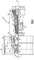
- FIG. 1 schematically illustrates a gas turbine engine 20.
- the gas turbine engine 20 is disclosed herein as a two-spool turbofan that generally incorporates a fan section 22, a compressor section 24, a combustor section 26 and a turbine section 28.
- Alternative engines might include an augmentor section (not shown) among other systems or features.
- the fan section 22 drives air along a bypass flow path B in a bypass duct defined within a nacelle 15, while the compressor section 24 drives air along a core flow path C for compression and communication into the combustor section 26 then expansion through the turbine section 28.
- the exemplary engine 20 generally includes a low speed spool 30 and a high speed spool 32 mounted for rotation about an engine central longitudinal axis A relative to an engine static structure 36 via several bearing systems 38. It should be understood that various bearing systems 38 at various locations may alternatively or additionally be provided, and the location of bearing systems 38 may be varied as appropriate to the application.
- the low speed spool 30 generally includes an inner shaft 40 that interconnects a fan 42, a first (or low) pressure compressor 44 and a first (or low) pressure turbine 46.
- the inner shaft 40 is connected to the fan 42 through a speed change mechanism, which in exemplary gas turbine engine 20 is illustrated as a geared architecture 48 to drive the fan 42 at a lower speed than the low speed spool 30.
- the high speed spool 32 includes an outer shaft 50 that interconnects a second (or high) pressure compressor 52 and a second (or high) pressure turbine 54.
- a combustor 56 is arranged in exemplary gas turbine 20 between the high pressure compressor 52 and the high pressure turbine 54.
- a mid-turbine frame 58 of the engine static structure 36 is arranged generally between the high pressure turbine 54 and the low pressure turbine 46.
- the mid-turbine frame 58 further supports bearing systems 38 in the turbine section 28.
- the inner shaft 40 and the outer shaft 50 are concentric and rotate via bearing systems 38 about the engine central longitudinal axis A which is collinear with their longitudinal axes.
- the core airflow is compressed by the low pressure compressor 44 then the high pressure compressor 52, mixed and burned with fuel in the combustor 56, then expanded over the high pressure turbine 54 and low pressure turbine 46.
- the mid-turbine frame 58 includes airfoils 60 which are in the core airflow path C.
- the turbines 46, 54 rotationally drive the respective low speed spool 30 and high speed spool 32 in response to the expansion.
- gear system 48 may be located aft of combustor section 26 or even aft of turbine section 28, and fan section 22 may be positioned forward or aft of the location of gear system 48.
- the engine 20 in one example is a high-bypass geared aircraft engine.
- the engine 20 bypass ratio is greater than about six (6:1), with an example embodiment being greater than about ten (10:1)
- the geared architecture 48 is an epicyclic gear train, such as a planetary gear system or other gear system, with a gear reduction ratio of greater than about 2.3
- the low pressure turbine 46 has a pressure ratio that is greater than about five (5:1).
- the engine 20 bypass ratio is greater than about ten (10:1)
- the fan diameter is significantly larger than that of the low pressure compressor 44
- the low pressure turbine 46 has a pressure ratio that is greater than about five (5:1).
- Low pressure turbine 46 pressure ratio is pressure measured prior to inlet of low pressure turbine 46 as related to the pressure at the outlet of the low pressure turbine 46 prior to an exhaust nozzle.
- the geared architecture 48 may be an epicycle gear train, such as a planetary gear system or other gear system, with a gear reduction ratio of greater than about 2.3:1. It should be understood, however, that the above parameters are only exemplary of one embodiment of a geared architecture engine and that the present invention is applicable to other gas turbine engines including direct drive turbofans.
- the fan section 22 of the engine 20 is designed for a particular flight condition -- typically cruise at about 0.8 Mach and about 35,000 feet (10,668 metres).
- the flight condition of 0.8 Mach and 35,000 ft (10,668 m), with the engine at its best fuel consumption - also known as "bucket cruise Thrust Specific Fuel Consumption ('TSFC')" - is the industry standard parameter of lbm of fuel being burned divided by lbf of thrust the engine produces at that minimum point.
- "Low fan pressure ratio” is the pressure ratio across the fan blade alone, without a Fan Exit Guide Vane (“FEGV”) system.
- the low fan pressure ratio as disclosed herein according to one non-limiting embodiment is less than about 1.45.
- the "Low corrected fan tip speed” as disclosed herein according to one non-limiting embodiment is less than about 1150 ft / second (350.5 m/second).
- Cooling air is typically drawn from the compressor section 24, such as via a compressor bleed, and provided to the cooled turbine component.
- Turbine engine components exposed to the hottest temperatures, such as turbine blades and vanes in the first stage aft of the combustor section 26, are allocated the highest amount of cooling air (referred to as the cooling air budget). Later stages of vanes, blades, blade outer air seals, and other turbine engine components that are further downstream are provided a limited cooling air budget, relative to the cooling air budget of the first stage blade.
- film cooling is frequently employed as a cooling method
- film cooling produces a significant drop in coolant pressure at the film cooling holes.
- the resultant pressure drop can reduce the ability to provide internal cooling downstream of the film cooling holes.
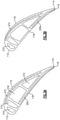
- Figure 2 illustrates an exemplary turbine second stage blade 100.
- the turbine second stage blade 100 includes a blade portion 110 extending from a platform 120 into the primary flow path of the gas turbine engine 20.
- a root portion 130 is received in the gas turbine engine static support structure, and maintains the turbine second stage blade 100 in position.
- the blade portion 110 has a forward edge, referred to as a leading edge 112, and an aft edge, referred to as a trailing edge 114.
- a cross section A-A of the blade portion 110 drawn from the leading edge 112 to the trailing edge 114 has an airfoil shaped profile (illustrated in Figures 3 and 4 ) with a suction surface 116 and a pressure surface 118 connecting the leading edge 112 to the trailing edge 114.
- the radially aligned internal cooling passages 210 form an internal cooling air flow path.
- the axially aligned skin core passage defines an axial flow path, and passes cooling air internally along the surface 118, thereby cooling the surface 118. Cooling air entering the axially aligned skin core passage exits the blade portion 110 through slots 119 in the trailing edge 114.
- additional openings connect the axially aligned skin core passage to a radially outward surface of the tip portion.
- a small portion of the air passing through the axially aligned skin core passage exits through the openings.
- the small portion of the air passing through the axially aligned skin core passage that exits through the openings can be less than 20% of the air in some examples, and less than 5% of the air in some examples.
- the blade 100 is created utilizing an investment casting process.
- the second stage blade 100 can be created using a process other than investment casting.
- the blade 100 is cast around a core defining a negative image of the internal cooling passages of the blade 100.
- the core is then removed from the component leaving the cooling passages empty.
- a skin core passage such as the above described skin core passage, is a passage formed around a thin sheet of material that conforms with the shape of the surface along which the skin core passage extends.
- the blade portion 110 is formed around the thin sheet of material, and the thin sheet is removed from the formed blade portion 110 once the second stage blade 100 has been cast. The result is a thin passage that extends along the surface to which the skin core passage is adjacent. Cooling air passing through the skin core passage 220 absorbs heat from the surface via convection, allowing for the surface to be actively cooled.
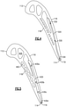
- Figure 3A illustrates a first embodiment cross section drawn along cross section A-A.
- multiple cooling passages 210 are defined between the suction surface 116 and the pressure surface 118.
- the cooling passages 210 are radially aligned so that a coolant, such as cooling air, flows through the cooling passage 210 radially relative to an axis defined by the gas turbine engine including the second stage blade 100.
- Each of the passages 210 is interconnected with at least one of the other passages 210 such that the passages 210 form a single cooling flow path through the second stage blade 100.
- radially aligned skin core passages 212 Defined immediately adjacent to the suction surface 116 are multiple radially aligned skin core passages 212. In alternative examples, a single radially aligned skin core passage may be utilized in place of the multiple passages 212.
- the axially aligned skin core passage 220 defines an axial coolant flow path, relative to the gas turbine engine including the second stage blade 100. Due to the reduced cooling air budget of the second stage blade 100, relative to a first stage blade, no film cooling holes or film cooling slots are included along the length of the axially aligned skin core passage 220. The lack of film cooling holes maintains the cooling air pressure throughout the axially aligned skin core passage 220 until the cooling air is expelled at the trailing edge 114 through cooling air outflow slots 119, or through openings connecting the axially aligned skin core passage 220 to the tip.
- the axially aligned skin core passage 220 illustrated in Figure 3A extends a majority of the axial length of the pressure surface 118, prior to being expelled out the slots 119.
- Figure 3B illustrates an alternate embodiment cross section drawn along cross section A-A, where the axially aligned skin core passage 220a extends less than 50% of the axial length of the pressure surface 118.
- the alternate embodiment configuration illustrated in Figure 3B can be utilized when only the aft portion of the pressure surface 118 requires the increased cooling provided by the skin core passage 220, or when the cooling budget is insufficient to allow for a full axial length cooling skin core passage 220.
- the utilization of the outlet slot 119 at the trailing edge allows approximately 100% of the cooling air entering the axially aligned skin core passage 220, 220a to be expelled from the second stage blade 100 at the trailing edge. In other words, no cooling air is expelled from the axially aligned skin core passage 220, 220a upstream of an outlet disposed at an aft most edge of the axially aligned skin core passage 220, 220a.
- the above described openings connecting the tip of the blade to the axially aligned skin core passage 220, 220a can allow a small portion of the cooling air to be expelled radially outward of the blade at the tip. In some embodiments, the amount of air expelled at the tip can be less than 20%. In other embodiments the amount of air expelled at the tip can be less than 5%.
- Figure 4 which falls outside the wording of the claims, illustrates an alternative cross section of the second stage blade 100 constructed using a refractory metal core.
- the blade portion 110 includes a leading edge 112, a trailing edge 114, a pressure surface 118 and a suction surface 116.
- an axially aligned skin core passage 320 extends along the suction surface 116, and provides cooling airflow as described above with regards to Figures 3A and 3B .
- the utilization of a refractory metal core for the casting results in an axial skin core passage 320 that has a uniform width 330 for the full length of the axial skin core passage 320.
- the uniform width 330 created by the refractory metal core can be extremely small, relative to other methods of creating cooling passages within a turbine engine component.
- Figure 5 which falls outside the wording of the claims illustrates the cross section of the second stage blade 100 illustrated in Figure 4 , cast around a ceramic core rather than a refractory metal core.
- Internal cooling passages 402 defined by the ceramic core are larger than the internal passages defined by a refractory metal core.
- Utilization of a ceramic core in the casting process further allows a width 430a-d of the skin core passage 420 to be varied along the axial length of the skin core passage 420.
- the width 430a at an entryway to the axial skin core passage 420 is maintained constant through a width 430b at the midway point through the axial skin core passage 420.
- the width slightly increases to a maximum width 430c, after which the width 430 is decreased to a minimum width 430d at the trailing edge 114.
- the speed at which cooling air is passed through the axial skin core passage 420 can be locally accelerated (when the width is narrower) and locally decelerated (when the width is wider) to adjust the convection capabilities of the cooling air passing through the skin core passage 420 for particular hot spots and cold spots.
- an axially aligned skin core passage that passes all coolant entering the skin core passage to an aft most exit to the skin core passage is capable of providing convective cooling to a surface of the turbine engine component without cooling air pressure loss when the cooling air budget provided to the turbine engine component is low.
- an axially aligned skin core passage such as is described above, can be utilized in conjunction with a cooling flow that has sufficient cooling air budget for film cooling upstream of the axially aligned skin core, or in a turbine engine component that utilizes multiple cooling air flow paths through the turbine engine component where one of the cooling air flow paths has sufficient budget for film cooling, but the cooling air flow path feeding the axially aligned skin core passage lacks sufficient budget.
- it can be beneficial to provide film cooling from the cooling air flow path, or the upstream portion of the cooling air flow path, where there is sufficient cooling air budget.
- inclusion of the axially aligned skin core passage prevents a direct film cooling hole between the higher budget cooling flow and the surface of the turbine engine component receiving film cooling.
Landscapes
- Engineering & Computer Science (AREA)
- Mechanical Engineering (AREA)
- General Engineering & Computer Science (AREA)
- Chemical & Material Sciences (AREA)
- Combustion & Propulsion (AREA)
- Turbine Rotor Nozzle Sealing (AREA)
Description
- The present disclosure relates generally to a turbine engine component that is a second or later turbine stage blade including an axially aligned skin core cooling passage.
- Gas turbine engines, such as those utilized in commercial and military aircraft, utilize a compressor section to draw air into a flow path, a combustor section to mix compressed air with a fuel and ignite the mixture, and a turbine section to expand the resultant combustion products. The expansion of the resultant combustion products drives the turbine section to rotate, which in turn drives the compressor section to rotate.
- As a result of the exposure to combustion products, components within the turbine section are subject to extreme heat. To prevent heat related fatigue and damage, the turbine components are actively cooled via internal cooling flow paths. Frequently air, or another coolant, is expelled from the internal cooling passages along the surface of the turbine engine component to create a film cooling effect on the exterior surface of the turbine engine component.
-
EP 1 783 327 A2 discloses a turbine engine component as set forth in the preamble of claim 1. - From a first aspect, the invention provides a turbine engine component as recited in claim 1.
- Features of embodiments of the invention are set forth in the dependent claims.
- These and other features of the present invention can be best understood from the following specification and drawings, the following of which is a brief description.
-
-
Figure 1 schematically illustrates an exemplary gas turbine engine. -
Figure 2 schematically illustrates a turbine engine component. -
Figure 3A schematically illustrates a cross section of a first embodiment turbine engine component according toFigure 2 . -
Figure 3B schematically illustrates a cross section of a second embodiment turbine engine component according toFigure 2 . -
Figure 4 schematically illustrates a cross section of an alternate turbine engine component falling outside the wording of the claims. -
Figure 5 schematically illustrates a cross section of another alternate turbine engine component falling outside the wording of the claims. -
Figure 1 schematically illustrates a gas turbine engine 20. The gas turbine engine 20 is disclosed herein as a two-spool turbofan that generally incorporates afan section 22, acompressor section 24, acombustor section 26 and aturbine section 28. Alternative engines might include an augmentor section (not shown) among other systems or features. Thefan section 22 drives air along a bypass flow path B in a bypass duct defined within a nacelle 15, while thecompressor section 24 drives air along a core flow path C for compression and communication into thecombustor section 26 then expansion through theturbine section 28. Although depicted as a two-spool turbofan gas turbine engine in the disclosed non-limiting embodiment, it should be understood that the concepts described herein are not limited to use with two-spool turbofans as the teachings may be applied to other types of turbine engines including three-spool architectures. - The exemplary engine 20 generally includes a
low speed spool 30 and ahigh speed spool 32 mounted for rotation about an engine central longitudinal axis A relative to an enginestatic structure 36 viaseveral bearing systems 38. It should be understood that various bearingsystems 38 at various locations may alternatively or additionally be provided, and the location of bearingsystems 38 may be varied as appropriate to the application. - The
low speed spool 30 generally includes aninner shaft 40 that interconnects afan 42, a first (or low)pressure compressor 44 and a first (or low)pressure turbine 46. Theinner shaft 40 is connected to thefan 42 through a speed change mechanism, which in exemplary gas turbine engine 20 is illustrated as a gearedarchitecture 48 to drive thefan 42 at a lower speed than thelow speed spool 30. Thehigh speed spool 32 includes anouter shaft 50 that interconnects a second (or high)pressure compressor 52 and a second (or high)pressure turbine 54. Acombustor 56 is arranged in exemplary gas turbine 20 between thehigh pressure compressor 52 and thehigh pressure turbine 54. Amid-turbine frame 58 of the enginestatic structure 36 is arranged generally between thehigh pressure turbine 54 and thelow pressure turbine 46. Themid-turbine frame 58 further supports bearingsystems 38 in theturbine section 28. Theinner shaft 40 and theouter shaft 50 are concentric and rotate viabearing systems 38 about the engine central longitudinal axis A which is collinear with their longitudinal axes. - The core airflow is compressed by the
low pressure compressor 44 then thehigh pressure compressor 52, mixed and burned with fuel in thecombustor 56, then expanded over thehigh pressure turbine 54 andlow pressure turbine 46. Themid-turbine frame 58 includes airfoils 60 which are in the core airflow path C. Theturbines low speed spool 30 andhigh speed spool 32 in response to the expansion. It will be appreciated that each of the positions of thefan section 22,compressor section 24,combustor section 26,turbine section 28, and fandrive gear system 48 may be varied. For example,gear system 48 may be located aft ofcombustor section 26 or even aft ofturbine section 28, andfan section 22 may be positioned forward or aft of the location ofgear system 48. - The engine 20 in one example is a high-bypass geared aircraft engine. In a further example, the engine 20 bypass ratio is greater than about six (6:1), with an example embodiment being greater than about ten (10:1), the geared
architecture 48 is an epicyclic gear train, such as a planetary gear system or other gear system, with a gear reduction ratio of greater than about 2.3 and thelow pressure turbine 46 has a pressure ratio that is greater than about five (5:1). In one disclosed embodiment, the engine 20 bypass ratio is greater than about ten (10:1), the fan diameter is significantly larger than that of thelow pressure compressor 44, and thelow pressure turbine 46 has a pressure ratio that is greater than about five (5:1).Low pressure turbine 46 pressure ratio is pressure measured prior to inlet oflow pressure turbine 46 as related to the pressure at the outlet of thelow pressure turbine 46 prior to an exhaust nozzle. The gearedarchitecture 48 may be an epicycle gear train, such as a planetary gear system or other gear system, with a gear reduction ratio of greater than about 2.3:1. It should be understood, however, that the above parameters are only exemplary of one embodiment of a geared architecture engine and that the present invention is applicable to other gas turbine engines including direct drive turbofans. - A significant amount of thrust is provided by the bypass flow B due to the high bypass ratio. The
fan section 22 of the engine 20 is designed for a particular flight condition -- typically cruise at about 0.8 Mach and about 35,000 feet (10,668 metres). The flight condition of 0.8 Mach and 35,000 ft (10,668 m), with the engine at its best fuel consumption - also known as "bucket cruise Thrust Specific Fuel Consumption ('TSFC')" - is the industry standard parameter of lbm of fuel being burned divided by lbf of thrust the engine produces at that minimum point. "Low fan pressure ratio" is the pressure ratio across the fan blade alone, without a Fan Exit Guide Vane ("FEGV") system. The low fan pressure ratio as disclosed herein according to one non-limiting embodiment is less than about 1.45. "Low corrected fan tip speed" is the actual fan tip speed in ft/sec divided by an industry standard temperature correction of [(Tram °R) / (518.7 °R)]^0.5 (°R = °K x 9/5). The "Low corrected fan tip speed" as disclosed herein according to one non-limiting embodiment is less than about 1150 ft / second (350.5 m/second). - Multiple components within the
turbine section 28 include internal cooling passages for active cooling. Cooling air is typically drawn from thecompressor section 24, such as via a compressor bleed, and provided to the cooled turbine component. Turbine engine components exposed to the hottest temperatures, such as turbine blades and vanes in the first stage aft of thecombustor section 26, are allocated the highest amount of cooling air (referred to as the cooling air budget). Later stages of vanes, blades, blade outer air seals, and other turbine engine components that are further downstream are provided a limited cooling air budget, relative to the cooling air budget of the first stage blade. - While film cooling is frequently employed as a cooling method, film cooling produces a significant drop in coolant pressure at the film cooling holes. In a blade, or other turbine engine component, having a limited cooling air budget, the resultant pressure drop can reduce the ability to provide internal cooling downstream of the film cooling holes.
- With continued reference to
Figure 1 ,Figure 2 illustrates an exemplary turbinesecond stage blade 100. The turbinesecond stage blade 100 includes ablade portion 110 extending from aplatform 120 into the primary flow path of the gas turbine engine 20. Aroot portion 130 is received in the gas turbine engine static support structure, and maintains the turbinesecond stage blade 100 in position. Theblade portion 110 has a forward edge, referred to as a leadingedge 112, and an aft edge, referred to as atrailing edge 114. A cross section A-A of theblade portion 110 drawn from the leadingedge 112 to thetrailing edge 114 has an airfoil shaped profile (illustrated inFigures 3 and4 ) with asuction surface 116 and apressure surface 118 connecting the leadingedge 112 to thetrailing edge 114. - Included within the
blade portion 110 are multiple radially aligned internal cooling passages 210 (illustrated inFigures 3 and4 ). The radially alignedinternal cooling passages 210 form an internal cooling air flow path. Along one surface of theblade portion 110, such as thepressure surface 118, is an axially aligned skin core passage. The axially aligned skin core passage defines an axial flow path, and passes cooling air internally along thesurface 118, thereby cooling thesurface 118. Cooling air entering the axially aligned skin core passage exits theblade portion 110 throughslots 119 in the trailingedge 114. In some example embodiments additional openings connect the axially aligned skin core passage to a radially outward surface of the tip portion. In such examples, a small portion of the air passing through the axially aligned skin core passage exits through the openings. The small portion of the air passing through the axially aligned skin core passage that exits through the openings can be less than 20% of the air in some examples, and less than 5% of the air in some examples. - In some examples, the
blade 100, illustrated inFigure 2 , is created utilizing an investment casting process. In alternative examples, thesecond stage blade 100 can be created using a process other than investment casting. In either case, theblade 100 is cast around a core defining a negative image of the internal cooling passages of theblade 100. The core is then removed from the component leaving the cooling passages empty. A skin core passage, such as the above described skin core passage, is a passage formed around a thin sheet of material that conforms with the shape of the surface along which the skin core passage extends. In the example ofFigure 2 , theblade portion 110 is formed around the thin sheet of material, and the thin sheet is removed from the formedblade portion 110 once thesecond stage blade 100 has been cast. The result is a thin passage that extends along the surface to which the skin core passage is adjacent. Cooling air passing through theskin core passage 220 absorbs heat from the surface via convection, allowing for the surface to be actively cooled. - With continued reference to
Figure 2 ,Figure 3A illustrates a first embodiment cross section drawn along cross section A-A. In the embodiment cross section ofFigure 3 ,multiple cooling passages 210 are defined between thesuction surface 116 and thepressure surface 118. Thecooling passages 210 are radially aligned so that a coolant, such as cooling air, flows through thecooling passage 210 radially relative to an axis defined by the gas turbine engine including thesecond stage blade 100. Each of thepassages 210 is interconnected with at least one of theother passages 210 such that thepassages 210 form a single cooling flow path through thesecond stage blade 100. - Defined immediately adjacent to the
suction surface 116 are multiple radially alignedskin core passages 212. In alternative examples, a single radially aligned skin core passage may be utilized in place of themultiple passages 212. - Immediately adjacent the
pressure surface 118 of thesecond stage blade 100 is an axially alignedskin core passage 220. The axially alignedskin core passage 220 defines an axial coolant flow path, relative to the gas turbine engine including thesecond stage blade 100. Due to the reduced cooling air budget of thesecond stage blade 100, relative to a first stage blade, no film cooling holes or film cooling slots are included along the length of the axially alignedskin core passage 220. The lack of film cooling holes maintains the cooling air pressure throughout the axially alignedskin core passage 220 until the cooling air is expelled at the trailingedge 114 through coolingair outflow slots 119, or through openings connecting the axially alignedskin core passage 220 to the tip. - The axially aligned
skin core passage 220 illustrated inFigure 3A extends a majority of the axial length of thepressure surface 118, prior to being expelled out theslots 119. With continued reference toFigure 3A, Figure 3B illustrates an alternate embodiment cross section drawn along cross section A-A, where the axially alignedskin core passage 220a extends less than 50% of the axial length of thepressure surface 118. The alternate embodiment configuration illustrated inFigure 3B can be utilized when only the aft portion of thepressure surface 118 requires the increased cooling provided by theskin core passage 220, or when the cooling budget is insufficient to allow for a full axial length coolingskin core passage 220. - In each of the embodiments of
Figures 3A and 3B , the utilization of theoutlet slot 119 at the trailing edge allows approximately 100% of the cooling air entering the axially alignedskin core passage second stage blade 100 at the trailing edge. In other words, no cooling air is expelled from the axially alignedskin core passage skin core passage skin core passage - With continued reference to
Figures 1-3B ,Figure 4 , which falls outside the wording of the claims, illustrates an alternative cross section of thesecond stage blade 100 constructed using a refractory metal core. As with the embodiment ofFigure 3A , theblade portion 110 includes aleading edge 112, a trailingedge 114, apressure surface 118 and asuction surface 116. In the illustrated arrangement ofFigure 4 , an axially alignedskin core passage 320 extends along thesuction surface 116, and provides cooling airflow as described above with regards toFigures 3A and 3B . The utilization of a refractory metal core for the casting results in an axialskin core passage 320 that has auniform width 330 for the full length of the axialskin core passage 320. Theuniform width 330 created by the refractory metal core can be extremely small, relative to other methods of creating cooling passages within a turbine engine component. - With continued reference to
Figures 1-4 ,Figure 5 , which falls outside the wording of the claims illustrates the cross section of thesecond stage blade 100 illustrated inFigure 4 , cast around a ceramic core rather than a refractory metal core.Internal cooling passages 402 defined by the ceramic core are larger than the internal passages defined by a refractory metal core. Utilization of a ceramic core in the casting process further allows awidth 430a-d of theskin core passage 420 to be varied along the axial length of theskin core passage 420. In the arrangement ofFigure 5 , thewidth 430a at an entryway to the axialskin core passage 420 is maintained constant through awidth 430b at the midway point through the axialskin core passage 420. After the midway point the width slightly increases to amaximum width 430c, after which the width 430 is decreased to aminimum width 430d at the trailingedge 114. By varying the width 430 of theskin core passage 420, the speed at which cooling air is passed through the axialskin core passage 420 can be locally accelerated (when the width is narrower) and locally decelerated (when the width is wider) to adjust the convection capabilities of the cooling air passing through theskin core passage 420 for particular hot spots and cold spots. - With general reference to
Figures 2-5 , an axially aligned skin core passage that passes all coolant entering the skin core passage to an aft most exit to the skin core passage is capable of providing convective cooling to a surface of the turbine engine component without cooling air pressure loss when the cooling air budget provided to the turbine engine component is low. - In some examples, an axially aligned skin core passage, such as is described above, can be utilized in conjunction with a cooling flow that has sufficient cooling air budget for film cooling upstream of the axially aligned skin core, or in a turbine engine component that utilizes multiple cooling air flow paths through the turbine engine component where one of the cooling air flow paths has sufficient budget for film cooling, but the cooling air flow path feeding the axially aligned skin core passage lacks sufficient budget. In such an example, it can be beneficial to provide film cooling from the cooling air flow path, or the upstream portion of the cooling air flow path, where there is sufficient cooling air budget. However, inclusion of the axially aligned skin core passage prevents a direct film cooling hole between the higher budget cooling flow and the surface of the turbine engine component receiving film cooling.
- It is further understood that any of the above described concepts can be used alone or in combination with any or all of the other above described concepts. Although an embodiment of this invention has been disclosed, a worker of ordinary skill in this art would recognize that certain modifications would come within the scope of this invention. For that reason, the following claims should be studied to determine the true scope and content of this invention.
Claims (6)
- A turbine engine component (100) comprising:a fore edge (112) connected to an aft edge (114) via a first surface (116) and a second surface (118);a plurality of cooling passages (210, 212) defined within the turbine engine component (100), wherein the plurality of cooling passages (210, 212) include a plurality of radially aligned internal cooling passages (210) that are radially aligned so that a coolant flows through the radially aligned internal cooling passages (210) radially relative to an axis (A) defined by a turbine engine (20) including the turbine engine component (100) and the plurality of cooling passages (210, 212) further include at least one radially aligned skin core passage (212) defining a radial cooling air flow path section relative to the axis (A) defined by a turbine engine (20) including the turbine engine component (100), and wherein the radially aligned skin core passage (212) is immediately adjacent said first surface (116); anda first skin core passage (220;220a) defined immediately adjacent said second surface (118), wherein at least 80% of coolant entering said first skin core passage (220;220a) is expelled from said turbine engine component (100) through slots (119) at said aft edge (114);wherein said turbine engine component (100) has an airfoil shaped profile, said fore edge (112) is a leading edge (112), said aft edge (114) is a trailing edge (114), said first surface (116) is a suction side (116) and said second surface (118) is a pressure side (118); and characterized in that:said first skin core passage (220;220a) defines an axial flow path relative to the axis (A) defined by a turbine engine (20) including the turbine engine component (100);no film cooling holes or film cooling slots are included along the length of the first skin core passage (220; 220a);each of the plurality of radially aligned internal cooling passages (210) and said first skin core passage (220;220a) are sections of a singular cooling flowpath;the first skin core passage (220;220a) is either:defined between two of the plurality of radially aligned internal cooling passages (210) that are closest to the aft edge (114) and said second surface (118), connected to the radially aligned internal cooling passage (210) that is second closest to the aft edge (114), and extends along said pressure side (118) for a majority of the axial length of the pressure side (118); ordefined between the radially aligned internal cooling passage (210) that is closest to the aft edge (114) and said second surface (118), connected to the radially aligned internal cooling passage (210) closest to the aft edge (114), and extends less than 50% of the axial length of the pressure side (118);and in thatthe turbine engine component is a second or later turbine stage blade (100).
- The turbine engine component (100) of any preceding claim, wherein said first skin core passage has a constant axial width.
- The turbine engine component (100) of claim 1, wherein said first skin core passage has a varied axial width.
- The turbine engine component (100) of claim 3, wherein the axial width of the first skin core passage is minimized at the aft edge (114).
- A gas turbine engine (20) comprising:a compressor section (24);a combustor section (26) fluidly connected to the compressor section (24) by a flowpath (C);a turbine section (28) fluidly connected to the combustor section (26) by the flowpath (C); andat least one turbine engine component (100), as claimed in any preceding claim, exposed to a fluid passing through said flowpath (C).
- The gas turbine engine (20) of claim 5, wherein coolant expelled from said turbine engine component (100) at said aft edge (114) is expelled into said flowpath (C).
Applications Claiming Priority (1)
| Application Number | Priority Date | Filing Date | Title |
|---|---|---|---|
| US14/707,092 US10323524B2 (en) | 2015-05-08 | 2015-05-08 | Axial skin core cooling passage for a turbine engine component |
Publications (3)
| Publication Number | Publication Date |
|---|---|
| EP3106616A1 EP3106616A1 (en) | 2016-12-21 |
| EP3106616B1 EP3106616B1 (en) | 2018-04-18 |
| EP3106616B2 true EP3106616B2 (en) | 2022-03-09 |
Family
ID=55919756
Family Applications (1)
| Application Number | Title | Priority Date | Filing Date |
|---|---|---|---|
| EP16168779.3A Active EP3106616B2 (en) | 2015-05-08 | 2016-05-09 | Axial skin core cooling passage for a turbine engine component |
Country Status (2)
| Country | Link |
|---|---|
| US (1) | US10323524B2 (en) |
| EP (1) | EP3106616B2 (en) |
Families Citing this family (10)
| Publication number | Priority date | Publication date | Assignee | Title |
|---|---|---|---|---|
| JP6223774B2 (en) * | 2013-10-15 | 2017-11-01 | 三菱日立パワーシステムズ株式会社 | gas turbine |
| JP6025940B1 (en) * | 2015-08-25 | 2016-11-16 | 三菱日立パワーシステムズ株式会社 | Turbine blade and gas turbine |
| US10465529B2 (en) | 2016-12-05 | 2019-11-05 | United Technologies Corporation | Leading edge hybrid cavities and cores for airfoils of gas turbine engine |
| US10989056B2 (en) | 2016-12-05 | 2021-04-27 | Raytheon Technologies Corporation | Integrated squealer pocket tip and tip shelf with hybrid and tip flag core |
| US10815800B2 (en) | 2016-12-05 | 2020-10-27 | Raytheon Technologies Corporation | Radially diffused tip flag |
| US10563521B2 (en) * | 2016-12-05 | 2020-02-18 | United Technologies Corporation | Aft flowing serpentine cavities and cores for airfoils of gas turbine engines |
| KR101901683B1 (en) * | 2017-02-06 | 2018-09-27 | 두산중공업 주식회사 | Gas Turbine Ring Segment Having Straight Type Cooling Hole, And Gas Turbine Having The Same |
| US10801344B2 (en) | 2017-12-18 | 2020-10-13 | Raytheon Technologies Corporation | Double wall turbine gas turbine engine vane with discrete opposing skin core cooling configuration |
| US11021968B2 (en) * | 2018-11-19 | 2021-06-01 | General Electric Company | Reduced cross flow linking cavities and method of casting |
| US11028702B2 (en) | 2018-12-13 | 2021-06-08 | Raytheon Technologies Corporation | Airfoil with cooling passage network having flow guides |
Citations (2)
| Publication number | Priority date | Publication date | Assignee | Title |
|---|---|---|---|---|
| DE69602513T2 (en) † | 1996-01-04 | 1999-12-23 | Societe Nationale D'etude Et De Construction De Moteurs D'aviation (S.N.E.C.M.A.), Paris | Cooled turbine guide vane |
| US7556476B1 (en) † | 2006-11-16 | 2009-07-07 | Florida Turbine Technologies, Inc. | Turbine airfoil with multiple near wall compartment cooling |
Family Cites Families (94)
| Publication number | Priority date | Publication date | Assignee | Title |
|---|---|---|---|---|
| NL88170C (en) * | 1952-10-31 | 1900-01-01 | ||
| US2879028A (en) * | 1954-03-31 | 1959-03-24 | Edward A Stalker | Cooled turbine blades |
| US3017159A (en) * | 1956-11-23 | 1962-01-16 | Curtiss Wright Corp | Hollow blade construction |
| US3191908A (en) * | 1961-05-02 | 1965-06-29 | Rolls Royce | Blades for fluid flow machines |
| US3275294A (en) * | 1963-11-14 | 1966-09-27 | Westinghouse Electric Corp | Elastic fluid apparatus |
| US3540810A (en) * | 1966-03-17 | 1970-11-17 | Gen Electric | Slanted partition for hollow airfoil vane insert |
| US3844678A (en) * | 1967-11-17 | 1974-10-29 | Gen Electric | Cooled high strength turbine bucket |
| US3574481A (en) * | 1968-05-09 | 1971-04-13 | James A Pyne Jr | Variable area cooled airfoil construction for gas turbines |
| US3736071A (en) * | 1970-11-27 | 1973-05-29 | Gen Electric | Bucket tip/collection slot combination for open-circuit liquid-cooled gas turbines |
| US4153386A (en) * | 1974-12-11 | 1979-05-08 | United Technologies Corporation | Air cooled turbine vanes |
| US4111604A (en) * | 1976-07-12 | 1978-09-05 | General Electric Company | Bucket tip construction for open circuit liquid cooled turbines |
| US4236870A (en) * | 1977-12-27 | 1980-12-02 | United Technologies Corporation | Turbine blade |
| US4218178A (en) * | 1978-03-31 | 1980-08-19 | General Motors Corporation | Turbine vane structure |
| US4314442A (en) * | 1978-10-26 | 1982-02-09 | Rice Ivan G | Steam-cooled blading with steam thermal barrier for reheat gas turbine combined with steam turbine |
| US4297077A (en) * | 1979-07-09 | 1981-10-27 | Westinghouse Electric Corp. | Cooled turbine vane |
| GB2163219B (en) * | 1981-10-31 | 1986-08-13 | Rolls Royce | Cooled turbine blade |
| GB2121483B (en) * | 1982-06-08 | 1985-02-13 | Rolls Royce | Cooled turbine blade for a gas turbine engine |
| JPH0756201B2 (en) | 1984-03-13 | 1995-06-14 | 株式会社東芝 | Gas turbine blades |
| US4770608A (en) * | 1985-12-23 | 1988-09-13 | United Technologies Corporation | Film cooled vanes and turbines |
| US5012853A (en) * | 1988-09-20 | 1991-05-07 | Sundstrand Corporation | Process for making articles with smooth complex internal geometries |
| RU1815334C (en) | 1990-04-16 | 1993-05-15 | Ленинградское научно-производственное объединение им.В.Я.Климова | Gas-turbine cooled blade |
| US5405242A (en) * | 1990-07-09 | 1995-04-11 | United Technologies Corporation | Cooled vane |
| FR2678318B1 (en) * | 1991-06-25 | 1993-09-10 | Snecma | COOLED VANE OF TURBINE DISTRIBUTOR. |
| US5243759A (en) * | 1991-10-07 | 1993-09-14 | United Technologies Corporation | Method of casting to control the cooling air flow rate of the airfoil trailing edge |
| US5660524A (en) * | 1992-07-13 | 1997-08-26 | General Electric Company | Airfoil blade having a serpentine cooling circuit and impingement cooling |
| US5484258A (en) * | 1994-03-01 | 1996-01-16 | General Electric Company | Turbine airfoil with convectively cooled double shell outer wall |
| US5378108A (en) * | 1994-03-25 | 1995-01-03 | United Technologies Corporation | Cooled turbine blade |
| US5603606A (en) * | 1994-11-14 | 1997-02-18 | Solar Turbines Incorporated | Turbine cooling system |
| US5702232A (en) * | 1994-12-13 | 1997-12-30 | United Technologies Corporation | Cooled airfoils for a gas turbine engine |
| US5820337A (en) * | 1995-01-03 | 1998-10-13 | General Electric Company | Double wall turbine parts |
| EP0742347A3 (en) | 1995-05-10 | 1998-04-01 | Allison Engine Company, Inc. | Turbine blade cooling |
| US5813836A (en) * | 1996-12-24 | 1998-09-29 | General Electric Company | Turbine blade |
| FR2782118B1 (en) * | 1998-08-05 | 2000-09-15 | Snecma | COOLED TURBINE BLADE WITH LEADING EDGE |
| US6126397A (en) * | 1998-12-22 | 2000-10-03 | United Technologies Corporation | Trailing edge cooling apparatus for a gas turbine airfoil |
| US6213714B1 (en) | 1999-06-29 | 2001-04-10 | Allison Advanced Development Company | Cooled airfoil |
| DE19939179B4 (en) * | 1999-08-20 | 2007-08-02 | Alstom | Coolable blade for a gas turbine |
| US6290463B1 (en) * | 1999-09-30 | 2001-09-18 | General Electric Company | Slotted impingement cooling of airfoil leading edge |
| US6254334B1 (en) * | 1999-10-05 | 2001-07-03 | United Technologies Corporation | Method and apparatus for cooling a wall within a gas turbine engine |
| US6402470B1 (en) | 1999-10-05 | 2002-06-11 | United Technologies Corporation | Method and apparatus for cooling a wall within a gas turbine engine |
| DE19963349A1 (en) * | 1999-12-27 | 2001-06-28 | Abb Alstom Power Ch Ag | Blade for gas turbines with throttle cross section at the rear edge |
| US6616406B2 (en) * | 2001-06-11 | 2003-09-09 | Alstom (Switzerland) Ltd | Airfoil trailing edge cooling construction |
| GB0114503D0 (en) | 2001-06-14 | 2001-08-08 | Rolls Royce Plc | Air cooled aerofoil |
| US6551062B2 (en) * | 2001-08-30 | 2003-04-22 | General Electric Company | Turbine airfoil for gas turbine engine |
| US6974308B2 (en) * | 2001-11-14 | 2005-12-13 | Honeywell International, Inc. | High effectiveness cooled turbine vane or blade |
| US6558122B1 (en) * | 2001-11-14 | 2003-05-06 | General Electric Company | Second-stage turbine bucket airfoil |
| US6981846B2 (en) * | 2003-03-12 | 2006-01-03 | Florida Turbine Technologies, Inc. | Vortex cooling of turbine blades |
| US20050006047A1 (en) * | 2003-07-10 | 2005-01-13 | General Electric Company | Investment casting method and cores and dies used therein |
| US7097425B2 (en) | 2003-08-08 | 2006-08-29 | United Technologies Corporation | Microcircuit cooling for a turbine airfoil |
| US6913064B2 (en) | 2003-10-15 | 2005-07-05 | United Technologies Corporation | Refractory metal core |
| US6981840B2 (en) * | 2003-10-24 | 2006-01-03 | General Electric Company | Converging pin cooled airfoil |
| US6984103B2 (en) * | 2003-11-20 | 2006-01-10 | General Electric Company | Triple circuit turbine blade |
| US20050118882A1 (en) | 2003-11-28 | 2005-06-02 | Chiang Shu M. | Electrical connector latching apparatus |
| US7118326B2 (en) * | 2004-06-17 | 2006-10-10 | Siemens Power Generation, Inc. | Cooled gas turbine vane |
| US7131818B2 (en) | 2004-11-02 | 2006-11-07 | United Technologies Corporation | Airfoil with three-pass serpentine cooling channel and microcircuit |
| US7478994B2 (en) * | 2004-11-23 | 2009-01-20 | United Technologies Corporation | Airfoil with supplemental cooling channel adjacent leading edge |
| US7156619B2 (en) * | 2004-12-21 | 2007-01-02 | Pratt & Whitney Canada Corp. | Internally cooled gas turbine airfoil and method |
| US7334991B2 (en) * | 2005-01-07 | 2008-02-26 | Siemens Power Generation, Inc. | Turbine blade tip cooling system |
| US7744347B2 (en) | 2005-11-08 | 2010-06-29 | United Technologies Corporation | Peripheral microcircuit serpentine cooling for turbine airfoils |
| US7311498B2 (en) | 2005-11-23 | 2007-12-25 | United Technologies Corporation | Microcircuit cooling for blades |
| US7364405B2 (en) * | 2005-11-23 | 2008-04-29 | United Technologies Corporation | Microcircuit cooling for vanes |
| US7303376B2 (en) * | 2005-12-02 | 2007-12-04 | Siemens Power Generation, Inc. | Turbine airfoil with outer wall cooling system and inner mid-chord hot gas receiving cavity |
| US7293961B2 (en) * | 2005-12-05 | 2007-11-13 | General Electric Company | Zigzag cooled turbine airfoil |
| EP1847684A1 (en) * | 2006-04-21 | 2007-10-24 | Siemens Aktiengesellschaft | Turbine blade |
| US7780413B2 (en) * | 2006-08-01 | 2010-08-24 | Siemens Energy, Inc. | Turbine airfoil with near wall inflow chambers |
| US7690894B1 (en) * | 2006-09-25 | 2010-04-06 | Florida Turbine Technologies, Inc. | Ceramic core assembly for serpentine flow circuit in a turbine blade |
| US7674093B2 (en) * | 2006-12-19 | 2010-03-09 | General Electric Company | Cluster bridged casting core |
| US7845906B2 (en) | 2007-01-24 | 2010-12-07 | United Technologies Corporation | Dual cut-back trailing edge for airfoils |
| US7871246B2 (en) | 2007-02-15 | 2011-01-18 | Siemens Energy, Inc. | Airfoil for a gas turbine |
| US7837441B2 (en) | 2007-02-16 | 2010-11-23 | United Technologies Corporation | Impingement skin core cooling for gas turbine engine blade |
| US7762775B1 (en) * | 2007-05-31 | 2010-07-27 | Florida Turbine Technologies, Inc. | Turbine airfoil with cooled thin trailing edge |
| US9163518B2 (en) * | 2008-03-18 | 2015-10-20 | United Technologies Corporation | Full coverage trailing edge microcircuit with alternating converging exits |
| US8105033B2 (en) * | 2008-06-05 | 2012-01-31 | United Technologies Corporation | Particle resistant in-wall cooling passage inlet |
| US8137068B2 (en) | 2008-11-21 | 2012-03-20 | United Technologies Corporation | Castings, casting cores, and methods |
| US8231329B2 (en) * | 2008-12-30 | 2012-07-31 | General Electric Company | Turbine blade cooling with a hollow airfoil configured to minimize a distance between a pin array section and the trailing edge of the air foil |
| US8721285B2 (en) * | 2009-03-04 | 2014-05-13 | Siemens Energy, Inc. | Turbine blade with incremental serpentine cooling channels beneath a thermal skin |
| US8398370B1 (en) | 2009-09-18 | 2013-03-19 | Florida Turbine Technologies, Inc. | Turbine blade with multi-impingement cooling |
| US9528382B2 (en) * | 2009-11-10 | 2016-12-27 | General Electric Company | Airfoil heat shield |
| US8511994B2 (en) * | 2009-11-23 | 2013-08-20 | United Technologies Corporation | Serpentine cored airfoil with body microcircuits |
| RU2543914C2 (en) * | 2010-03-19 | 2015-03-10 | Альстом Текнолоджи Лтд | Gas turbine vane with aerodynamic profile and profiled holes on back edge for cooling agent discharge |
| US9121290B2 (en) * | 2010-05-06 | 2015-09-01 | United Technologies Corporation | Turbine airfoil with body microcircuits terminating in platform |
| US8585351B2 (en) * | 2010-06-23 | 2013-11-19 | Ooo Siemens | Gas turbine blade |
| EP2426317A1 (en) * | 2010-09-03 | 2012-03-07 | Siemens Aktiengesellschaft | Turbine blade for a gas turbine |
| US9017025B2 (en) * | 2011-04-22 | 2015-04-28 | Siemens Energy, Inc. | Serpentine cooling circuit with T-shaped partitions in a turbine airfoil |
| US8714927B1 (en) | 2011-07-12 | 2014-05-06 | United Technologies Corporation | Microcircuit skin core cut back to reduce microcircuit trailing edge stresses |
| US20130243575A1 (en) | 2012-03-13 | 2013-09-19 | United Technologies Corporation | Cooling pedestal array |
| US8985940B2 (en) * | 2012-03-30 | 2015-03-24 | Solar Turbines Incorporated | Turbine cooling apparatus |
| US9296039B2 (en) * | 2012-04-24 | 2016-03-29 | United Technologies Corporation | Gas turbine engine airfoil impingement cooling |
| JP2015527530A (en) | 2012-08-20 | 2015-09-17 | アルストム テクノロジー リミテッドALSTOM Technology Ltd | Internally cooled wings for rotating machinery |
| US9115590B2 (en) | 2012-09-26 | 2015-08-25 | United Technologies Corporation | Gas turbine engine airfoil cooling circuit |
| US9835035B2 (en) | 2013-03-12 | 2017-12-05 | Howmet Corporation | Cast-in cooling features especially for turbine airfoils |
| US8985949B2 (en) * | 2013-04-29 | 2015-03-24 | Siemens Aktiengesellschaft | Cooling system including wavy cooling chamber in a trailing edge portion of an airfoil assembly |
| US10323525B2 (en) | 2013-07-12 | 2019-06-18 | United Technologies Corporation | Gas turbine engine component cooling with resupply of cooling passage |
| WO2015061117A1 (en) | 2013-10-24 | 2015-04-30 | United Technologies Corporation | Airfoil with skin core cooling |
| EP3063389B1 (en) | 2013-10-30 | 2022-04-13 | Raytheon Technologies Corporation | Bore-cooled film dispensing pedestals |
-
2015
- 2015-05-08 US US14/707,092 patent/US10323524B2/en active Active
-
2016
- 2016-05-09 EP EP16168779.3A patent/EP3106616B2/en active Active
Patent Citations (2)
| Publication number | Priority date | Publication date | Assignee | Title |
|---|---|---|---|---|
| DE69602513T2 (en) † | 1996-01-04 | 1999-12-23 | Societe Nationale D'etude Et De Construction De Moteurs D'aviation (S.N.E.C.M.A.), Paris | Cooled turbine guide vane |
| US7556476B1 (en) † | 2006-11-16 | 2009-07-07 | Florida Turbine Technologies, Inc. | Turbine airfoil with multiple near wall compartment cooling |
Also Published As
| Publication number | Publication date |
|---|---|
| EP3106616B1 (en) | 2018-04-18 |
| US20160326884A1 (en) | 2016-11-10 |
| US10323524B2 (en) | 2019-06-18 |
| EP3106616A1 (en) | 2016-12-21 |
Similar Documents
| Publication | Publication Date | Title |
|---|---|---|
| EP3106616B2 (en) | Axial skin core cooling passage for a turbine engine component | |
| US11143039B2 (en) | Turbine engine component including an axially aligned skin core passage interrupted by a pedestal | |
| EP2952681B1 (en) | Turbine stage cooling and corresponding method | |
| EP2977556B1 (en) | Airfoil, gas turbine engine assembly, and corresponding cooling method | |
| EP3009599A1 (en) | Gas turbine engine component with film cooling hole feature | |
| EP2977555B1 (en) | Airfoil platform with cooling channels | |
| EP3091184B1 (en) | Turbine airfoil leading edge cooling | |
| EP3084136B1 (en) | Rotor blade and corresponding method of cooling a platform of a rotor blade | |
| US10982552B2 (en) | Gas turbine engine component with film cooling hole | |
| EP3061910B1 (en) | Gas turbine engine airfoil and corresponding method of forming | |
| EP3094823B1 (en) | Gas turbine engine component and corresponding gas turbine engine | |
| EP3126640B1 (en) | Active clearance control for gas turbine engine | |
| EP2960433B1 (en) | Gas turbine engine airfoil comprising angled cooling passages in the leading edge | |
| EP3112596A1 (en) | Gas turbine engine airfoil with bi-axial skin cooling passage and corresponding gas turbine engine | |
| EP3805527B1 (en) | Cooled cooling air for blade air seal through outer chamber | |
| EP3045666B1 (en) | Airfoil platform with cooling feed orifices | |
| EP3450686B1 (en) | Turbine vane cluster including enhanced platform cooling | |
| US20180038236A1 (en) | Gas turbine engine stator vane baffle arrangement | |
| EP3181869B1 (en) | Compressor core inner diameter cooling | |
| EP2977557B1 (en) | Cooled airfoil structure and corresponding cooling method | |
| EP3832071B1 (en) | Gas turbine engine flowpath component including vectored cooling flow holes | |
| EP2975222A1 (en) | Cooled pocket in a turbine vane platform |
Legal Events
| Date | Code | Title | Description |
|---|---|---|---|
| PUAI | Public reference made under article 153(3) epc to a published international application that has entered the european phase |
Free format text: ORIGINAL CODE: 0009012 |
|
| STAA | Information on the status of an ep patent application or granted ep patent |
Free format text: STATUS: THE APPLICATION HAS BEEN PUBLISHED |
|
| AK | Designated contracting states |
Kind code of ref document: A1 Designated state(s): AL AT BE BG CH CY CZ DE DK EE ES FI FR GB GR HR HU IE IS IT LI LT LU LV MC MK MT NL NO PL PT RO RS SE SI SK SM TR |
|
| AX | Request for extension of the european patent |
Extension state: BA ME |
|
| STAA | Information on the status of an ep patent application or granted ep patent |
Free format text: STATUS: REQUEST FOR EXAMINATION WAS MADE |
|
| 17P | Request for examination filed |
Effective date: 20170621 |
|
| RBV | Designated contracting states (corrected) |
Designated state(s): AL AT BE BG CH CY CZ DE DK EE ES FI FR GB GR HR HU IE IS IT LI LT LU LV MC MK MT NL NO PL PT RO RS SE SI SK SM TR |
|
| RIC1 | Information provided on ipc code assigned before grant |
Ipc: F01D 11/24 20060101ALI20170901BHEP Ipc: F01D 5/18 20060101AFI20170901BHEP Ipc: F02C 3/04 20060101ALI20170901BHEP Ipc: F02C 7/18 20060101ALI20170901BHEP |
|
| GRAP | Despatch of communication of intention to grant a patent |
Free format text: ORIGINAL CODE: EPIDOSNIGR1 |
|
| STAA | Information on the status of an ep patent application or granted ep patent |
Free format text: STATUS: GRANT OF PATENT IS INTENDED |
|
| INTG | Intention to grant announced |
Effective date: 20171020 |
|
| GRAS | Grant fee paid |
Free format text: ORIGINAL CODE: EPIDOSNIGR3 |
|
| GRAA | (expected) grant |
Free format text: ORIGINAL CODE: 0009210 |
|
| STAA | Information on the status of an ep patent application or granted ep patent |
Free format text: STATUS: THE PATENT HAS BEEN GRANTED |
|
| AK | Designated contracting states |
Kind code of ref document: B1 Designated state(s): AL AT BE BG CH CY CZ DE DK EE ES FI FR GB GR HR HU IE IS IT LI LT LU LV MC MK MT NL NO PL PT RO RS SE SI SK SM TR |
|
| REG | Reference to a national code |
Ref country code: GB Ref legal event code: FG4D |
|
| REG | Reference to a national code |
Ref country code: CH Ref legal event code: EP |
|
| REG | Reference to a national code |
Ref country code: AT Ref legal event code: REF Ref document number: 990699 Country of ref document: AT Kind code of ref document: T Effective date: 20180515 |
|
| REG | Reference to a national code |
Ref country code: IE Ref legal event code: FG4D |
|
| REG | Reference to a national code |
Ref country code: DE Ref legal event code: R096 Ref document number: 602016002491 Country of ref document: DE |
|
| REG | Reference to a national code |
Ref country code: FR Ref legal event code: PLFP Year of fee payment: 3 |
|
| REG | Reference to a national code |
Ref country code: NL Ref legal event code: MP Effective date: 20180418 |
|
| REG | Reference to a national code |
Ref country code: LT Ref legal event code: MG4D |
|
| PG25 | Lapsed in a contracting state [announced via postgrant information from national office to epo] |
Ref country code: NL Free format text: LAPSE BECAUSE OF FAILURE TO SUBMIT A TRANSLATION OF THE DESCRIPTION OR TO PAY THE FEE WITHIN THE PRESCRIBED TIME-LIMIT Effective date: 20180418 |
|
| PG25 | Lapsed in a contracting state [announced via postgrant information from national office to epo] |
Ref country code: NO Free format text: LAPSE BECAUSE OF FAILURE TO SUBMIT A TRANSLATION OF THE DESCRIPTION OR TO PAY THE FEE WITHIN THE PRESCRIBED TIME-LIMIT Effective date: 20180718 Ref country code: ES Free format text: LAPSE BECAUSE OF FAILURE TO SUBMIT A TRANSLATION OF THE DESCRIPTION OR TO PAY THE FEE WITHIN THE PRESCRIBED TIME-LIMIT Effective date: 20180418 Ref country code: LT Free format text: LAPSE BECAUSE OF FAILURE TO SUBMIT A TRANSLATION OF THE DESCRIPTION OR TO PAY THE FEE WITHIN THE PRESCRIBED TIME-LIMIT Effective date: 20180418 Ref country code: PL Free format text: LAPSE BECAUSE OF FAILURE TO SUBMIT A TRANSLATION OF THE DESCRIPTION OR TO PAY THE FEE WITHIN THE PRESCRIBED TIME-LIMIT Effective date: 20180418 Ref country code: SE Free format text: LAPSE BECAUSE OF FAILURE TO SUBMIT A TRANSLATION OF THE DESCRIPTION OR TO PAY THE FEE WITHIN THE PRESCRIBED TIME-LIMIT Effective date: 20180418 Ref country code: AL Free format text: LAPSE BECAUSE OF FAILURE TO SUBMIT A TRANSLATION OF THE DESCRIPTION OR TO PAY THE FEE WITHIN THE PRESCRIBED TIME-LIMIT Effective date: 20180418 Ref country code: FI Free format text: LAPSE BECAUSE OF FAILURE TO SUBMIT A TRANSLATION OF THE DESCRIPTION OR TO PAY THE FEE WITHIN THE PRESCRIBED TIME-LIMIT Effective date: 20180418 Ref country code: BG Free format text: LAPSE BECAUSE OF FAILURE TO SUBMIT A TRANSLATION OF THE DESCRIPTION OR TO PAY THE FEE WITHIN THE PRESCRIBED TIME-LIMIT Effective date: 20180718 |
|
| PG25 | Lapsed in a contracting state [announced via postgrant information from national office to epo] |
Ref country code: HR Free format text: LAPSE BECAUSE OF FAILURE TO SUBMIT A TRANSLATION OF THE DESCRIPTION OR TO PAY THE FEE WITHIN THE PRESCRIBED TIME-LIMIT Effective date: 20180418 Ref country code: RS Free format text: LAPSE BECAUSE OF FAILURE TO SUBMIT A TRANSLATION OF THE DESCRIPTION OR TO PAY THE FEE WITHIN THE PRESCRIBED TIME-LIMIT Effective date: 20180418 Ref country code: LV Free format text: LAPSE BECAUSE OF FAILURE TO SUBMIT A TRANSLATION OF THE DESCRIPTION OR TO PAY THE FEE WITHIN THE PRESCRIBED TIME-LIMIT Effective date: 20180418 Ref country code: GR Free format text: LAPSE BECAUSE OF FAILURE TO SUBMIT A TRANSLATION OF THE DESCRIPTION OR TO PAY THE FEE WITHIN THE PRESCRIBED TIME-LIMIT Effective date: 20180719 |
|
| REG | Reference to a national code |
Ref country code: AT Ref legal event code: MK05 Ref document number: 990699 Country of ref document: AT Kind code of ref document: T Effective date: 20180418 |
|
| PG25 | Lapsed in a contracting state [announced via postgrant information from national office to epo] |
Ref country code: PT Free format text: LAPSE BECAUSE OF FAILURE TO SUBMIT A TRANSLATION OF THE DESCRIPTION OR TO PAY THE FEE WITHIN THE PRESCRIBED TIME-LIMIT Effective date: 20180820 |
|
| REG | Reference to a national code |
Ref country code: DE Ref legal event code: R026 Ref document number: 602016002491 Country of ref document: DE |
|
| PLBI | Opposition filed |
Free format text: ORIGINAL CODE: 0009260 |
|
| REG | Reference to a national code |
Ref country code: BE Ref legal event code: MM Effective date: 20180531 |
|
| PG25 | Lapsed in a contracting state [announced via postgrant information from national office to epo] |
Ref country code: SK Free format text: LAPSE BECAUSE OF FAILURE TO SUBMIT A TRANSLATION OF THE DESCRIPTION OR TO PAY THE FEE WITHIN THE PRESCRIBED TIME-LIMIT Effective date: 20180418 Ref country code: EE Free format text: LAPSE BECAUSE OF FAILURE TO SUBMIT A TRANSLATION OF THE DESCRIPTION OR TO PAY THE FEE WITHIN THE PRESCRIBED TIME-LIMIT Effective date: 20180418 Ref country code: DK Free format text: LAPSE BECAUSE OF FAILURE TO SUBMIT A TRANSLATION OF THE DESCRIPTION OR TO PAY THE FEE WITHIN THE PRESCRIBED TIME-LIMIT Effective date: 20180418 Ref country code: MC Free format text: LAPSE BECAUSE OF FAILURE TO SUBMIT A TRANSLATION OF THE DESCRIPTION OR TO PAY THE FEE WITHIN THE PRESCRIBED TIME-LIMIT Effective date: 20180418 Ref country code: AT Free format text: LAPSE BECAUSE OF FAILURE TO SUBMIT A TRANSLATION OF THE DESCRIPTION OR TO PAY THE FEE WITHIN THE PRESCRIBED TIME-LIMIT Effective date: 20180418 Ref country code: RO Free format text: LAPSE BECAUSE OF FAILURE TO SUBMIT A TRANSLATION OF THE DESCRIPTION OR TO PAY THE FEE WITHIN THE PRESCRIBED TIME-LIMIT Effective date: 20180418 Ref country code: CZ Free format text: LAPSE BECAUSE OF FAILURE TO SUBMIT A TRANSLATION OF THE DESCRIPTION OR TO PAY THE FEE WITHIN THE PRESCRIBED TIME-LIMIT Effective date: 20180418 |
|
| PLAX | Notice of opposition and request to file observation + time limit sent |
Free format text: ORIGINAL CODE: EPIDOSNOBS2 |
|
| 26 | Opposition filed |
Opponent name: SAFRAN AIRCRAFT ENGINES Effective date: 20190115 Opponent name: SIEMENS AKTIENGESELLSCHAFT Effective date: 20190115 |
|
| REG | Reference to a national code |
Ref country code: IE Ref legal event code: MM4A |
|
| PG25 | Lapsed in a contracting state [announced via postgrant information from national office to epo] |
Ref country code: SM Free format text: LAPSE BECAUSE OF FAILURE TO SUBMIT A TRANSLATION OF THE DESCRIPTION OR TO PAY THE FEE WITHIN THE PRESCRIBED TIME-LIMIT Effective date: 20180418 Ref country code: IT Free format text: LAPSE BECAUSE OF FAILURE TO SUBMIT A TRANSLATION OF THE DESCRIPTION OR TO PAY THE FEE WITHIN THE PRESCRIBED TIME-LIMIT Effective date: 20180418 |
|
| PG25 | Lapsed in a contracting state [announced via postgrant information from national office to epo] |
Ref country code: LU Free format text: LAPSE BECAUSE OF NON-PAYMENT OF DUE FEES Effective date: 20180509 |
|
| PG25 | Lapsed in a contracting state [announced via postgrant information from national office to epo] |
Ref country code: IE Free format text: LAPSE BECAUSE OF NON-PAYMENT OF DUE FEES Effective date: 20180509 |
|
| PG25 | Lapsed in a contracting state [announced via postgrant information from national office to epo] |
Ref country code: BE Free format text: LAPSE BECAUSE OF NON-PAYMENT OF DUE FEES Effective date: 20180531 Ref country code: SI Free format text: LAPSE BECAUSE OF FAILURE TO SUBMIT A TRANSLATION OF THE DESCRIPTION OR TO PAY THE FEE WITHIN THE PRESCRIBED TIME-LIMIT Effective date: 20180418 |
|
| PLBB | Reply of patent proprietor to notice(s) of opposition received |
Free format text: ORIGINAL CODE: EPIDOSNOBS3 |
|
| REG | Reference to a national code |
Ref country code: CH Ref legal event code: PL |
|
| PG25 | Lapsed in a contracting state [announced via postgrant information from national office to epo] |
Ref country code: MT Free format text: LAPSE BECAUSE OF NON-PAYMENT OF DUE FEES Effective date: 20180509 Ref country code: CH Free format text: LAPSE BECAUSE OF NON-PAYMENT OF DUE FEES Effective date: 20190531 Ref country code: LI Free format text: LAPSE BECAUSE OF NON-PAYMENT OF DUE FEES Effective date: 20190531 |
|
| PG25 | Lapsed in a contracting state [announced via postgrant information from national office to epo] |
Ref country code: TR Free format text: LAPSE BECAUSE OF FAILURE TO SUBMIT A TRANSLATION OF THE DESCRIPTION OR TO PAY THE FEE WITHIN THE PRESCRIBED TIME-LIMIT Effective date: 20180418 |
|
| PG25 | Lapsed in a contracting state [announced via postgrant information from national office to epo] |
Ref country code: CY Free format text: LAPSE BECAUSE OF FAILURE TO SUBMIT A TRANSLATION OF THE DESCRIPTION OR TO PAY THE FEE WITHIN THE PRESCRIBED TIME-LIMIT Effective date: 20180418 Ref country code: HU Free format text: LAPSE BECAUSE OF FAILURE TO SUBMIT A TRANSLATION OF THE DESCRIPTION OR TO PAY THE FEE WITHIN THE PRESCRIBED TIME-LIMIT; INVALID AB INITIO Effective date: 20160509 Ref country code: MK Free format text: LAPSE BECAUSE OF NON-PAYMENT OF DUE FEES Effective date: 20180418 |
|
| RAP2 | Party data changed (patent owner data changed or rights of a patent transferred) |
Owner name: RAYTHEON TECHNOLOGIES CORPORATION |
|
| PG25 | Lapsed in a contracting state [announced via postgrant information from national office to epo] |
Ref country code: IS Free format text: LAPSE BECAUSE OF FAILURE TO SUBMIT A TRANSLATION OF THE DESCRIPTION OR TO PAY THE FEE WITHIN THE PRESCRIBED TIME-LIMIT Effective date: 20180818 |
|
| PUAH | Patent maintained in amended form |
Free format text: ORIGINAL CODE: 0009272 |
|
| STAA | Information on the status of an ep patent application or granted ep patent |
Free format text: STATUS: PATENT MAINTAINED AS AMENDED |
|
| 27A | Patent maintained in amended form |
Effective date: 20220309 |
|
| AK | Designated contracting states |
Kind code of ref document: B2 Designated state(s): AL AT BE BG CH CY CZ DE DK EE ES FI FR GB GR HR HU IE IS IT LI LT LU LV MC MK MT NL NO PL PT RO RS SE SI SK SM TR |
|
| REG | Reference to a national code |
Ref country code: DE Ref legal event code: R102 Ref document number: 602016002491 Country of ref document: DE |
|
| REG | Reference to a national code |
Ref country code: DE Ref legal event code: R081 Ref document number: 602016002491 Country of ref document: DE Owner name: RAYTHEON TECHNOLOGIES CORPORATION (N.D.GES.D.S, US Free format text: FORMER OWNER: UNITED TECHNOLOGIES CORPORATION, FARMINGTON, CONN., US Ref country code: DE Ref legal event code: R081 Ref document number: 602016002491 Country of ref document: DE Owner name: RTX CORPORATION (N.D.GES.D. STAATES DELAWARE),, US Free format text: FORMER OWNER: UNITED TECHNOLOGIES CORPORATION, FARMINGTON, CONN., US |
|
| P01 | Opt-out of the competence of the unified patent court (upc) registered |
Effective date: 20230520 |
|
| PGFP | Annual fee paid to national office [announced via postgrant information from national office to epo] |
Ref country code: DE Payment date: 20250423 Year of fee payment: 10 |
|
| PGFP | Annual fee paid to national office [announced via postgrant information from national office to epo] |
Ref country code: GB Payment date: 20250423 Year of fee payment: 10 |
|
| PGFP | Annual fee paid to national office [announced via postgrant information from national office to epo] |
Ref country code: FR Payment date: 20250423 Year of fee payment: 10 |
|
| REG | Reference to a national code |
Ref country code: DE Ref legal event code: R081 Ref document number: 602016002491 Country of ref document: DE Owner name: RTX CORPORATION (N.D.GES.D. STAATES DELAWARE),, US Free format text: FORMER OWNER: RAYTHEON TECHNOLOGIES CORPORATION (N.D.GES.D.STAATES DELAWARE), ARLINGTON, VA, US |