EP3106612A1 - Gas turbine arrangement - Google Patents
Gas turbine arrangement Download PDFInfo
- Publication number
- EP3106612A1 EP3106612A1 EP16172903.3A EP16172903A EP3106612A1 EP 3106612 A1 EP3106612 A1 EP 3106612A1 EP 16172903 A EP16172903 A EP 16172903A EP 3106612 A1 EP3106612 A1 EP 3106612A1
- Authority
- EP
- European Patent Office
- Prior art keywords
- drive shaft
- turbine drive
- turbine
- shaft
- surface portion
- Prior art date
- Legal status (The legal status is an assumption and is not a legal conclusion. Google has not performed a legal analysis and makes no representation as to the accuracy of the status listed.)
- Granted
Links
- 230000001419 dependent effect Effects 0.000 claims 1
- 238000002485 combustion reaction Methods 0.000 description 5
- 230000001141 propulsive effect Effects 0.000 description 3
- 230000004323 axial length Effects 0.000 description 2
- 238000013461 design Methods 0.000 description 2
- 239000000446 fuel Substances 0.000 description 2
- 238000012546 transfer Methods 0.000 description 2
- 230000007704 transition Effects 0.000 description 2
- 230000002411 adverse Effects 0.000 description 1
- 230000000712 assembly Effects 0.000 description 1
- 238000000429 assembly Methods 0.000 description 1
- 238000005452 bending Methods 0.000 description 1
- 230000000295 complement effect Effects 0.000 description 1
- 238000011161 development Methods 0.000 description 1
- 230000018109 developmental process Effects 0.000 description 1
- 238000005516 engineering process Methods 0.000 description 1
- 206010016256 fatigue Diseases 0.000 description 1
- 230000002349 favourable effect Effects 0.000 description 1
- 238000003780 insertion Methods 0.000 description 1
- 230000037431 insertion Effects 0.000 description 1
- 238000004519 manufacturing process Methods 0.000 description 1
- 239000000203 mixture Substances 0.000 description 1
- 238000012986 modification Methods 0.000 description 1
- 230000004048 modification Effects 0.000 description 1
- 238000000926 separation method Methods 0.000 description 1
- 230000008719 thickening Effects 0.000 description 1
- 238000011144 upstream manufacturing Methods 0.000 description 1
Images



Classifications
-
- F—MECHANICAL ENGINEERING; LIGHTING; HEATING; WEAPONS; BLASTING
- F01—MACHINES OR ENGINES IN GENERAL; ENGINE PLANTS IN GENERAL; STEAM ENGINES
- F01D—NON-POSITIVE DISPLACEMENT MACHINES OR ENGINES, e.g. STEAM TURBINES
- F01D5/00—Blades; Blade-carrying members; Heating, heat-insulating, cooling or antivibration means on the blades or the members
- F01D5/02—Blade-carrying members, e.g. rotors
- F01D5/026—Shaft to shaft connections
-
- F—MECHANICAL ENGINEERING; LIGHTING; HEATING; WEAPONS; BLASTING
- F02—COMBUSTION ENGINES; HOT-GAS OR COMBUSTION-PRODUCT ENGINE PLANTS
- F02C—GAS-TURBINE PLANTS; AIR INTAKES FOR JET-PROPULSION PLANTS; CONTROLLING FUEL SUPPLY IN AIR-BREATHING JET-PROPULSION PLANTS
- F02C7/00—Features, components parts, details or accessories, not provided for in, or of interest apart form groups F02C1/00 - F02C6/00; Air intakes for jet-propulsion plants
- F02C7/36—Power transmission arrangements between the different shafts of the gas turbine plant, or between the gas-turbine plant and the power user
-
- F—MECHANICAL ENGINEERING; LIGHTING; HEATING; WEAPONS; BLASTING
- F05—INDEXING SCHEMES RELATING TO ENGINES OR PUMPS IN VARIOUS SUBCLASSES OF CLASSES F01-F04
- F05D—INDEXING SCHEME FOR ASPECTS RELATING TO NON-POSITIVE-DISPLACEMENT MACHINES OR ENGINES, GAS-TURBINES OR JET-PROPULSION PLANTS
- F05D2240/00—Components
- F05D2240/60—Shafts
- F05D2240/61—Hollow
-
- F—MECHANICAL ENGINEERING; LIGHTING; HEATING; WEAPONS; BLASTING
- F16—ENGINEERING ELEMENTS AND UNITS; GENERAL MEASURES FOR PRODUCING AND MAINTAINING EFFECTIVE FUNCTIONING OF MACHINES OR INSTALLATIONS; THERMAL INSULATION IN GENERAL
- F16D—COUPLINGS FOR TRANSMITTING ROTATION; CLUTCHES; BRAKES
- F16D1/00—Couplings for rigidly connecting two coaxial shafts or other movable machine elements
- F16D1/06—Couplings for rigidly connecting two coaxial shafts or other movable machine elements for attachment of a member on a shaft or on a shaft-end
-
- F—MECHANICAL ENGINEERING; LIGHTING; HEATING; WEAPONS; BLASTING
- F16—ENGINEERING ELEMENTS AND UNITS; GENERAL MEASURES FOR PRODUCING AND MAINTAINING EFFECTIVE FUNCTIONING OF MACHINES OR INSTALLATIONS; THERMAL INSULATION IN GENERAL
- F16D—COUPLINGS FOR TRANSMITTING ROTATION; CLUTCHES; BRAKES
- F16D1/00—Couplings for rigidly connecting two coaxial shafts or other movable machine elements
- F16D1/10—Quick-acting couplings in which the parts are connected by simply bringing them together axially
- F16D2001/103—Quick-acting couplings in which the parts are connected by simply bringing them together axially the torque is transmitted via splined connections
Definitions
- the invention relates to joints between shafts in a gas turbine and particularly splined joints that transfer load from a turbine to a compressor.
- joints between shafts are often located in areas of the engine that are subject to adverse conditions such as high temperature.
- the joints are also subject to high torque loads.
- Some engine architectures require multiple turbine stages to drive the compressor.
- FIG. 4 A schematic view of a joint between the compressor, first turbine stage 16a and second turbine stage 16b of a known gas turbine engine is shown in Figure 4.
- the compressor shaft 110 is joined to a first turbine shaft 112 through a bolted flange 114 the second turbine stage 116b is connected to the first turbine stage 116a through a splined arrangement 118.
- the flange 114 is annular and extends circumferentially around the engine axis 120.
- the bolts are located radially inside the shafts to isolate them from the heat of the combustion chamber 122 which can be significant and limit the life of the joint.
- the flange determines in part the spacing of the compressor shaft from the axis of the engine that means that the compressor shaft diameter is large, which increases the mass of the shaft and the centrifugal forces acting on it.
- the multiple bolts required at each joint 114 take assembly time and add to the weight of the arrangement. The large part count also increase the risk that one or more of the bolts may work loose in operation and become released into the engine.
- a gas turbine drive shaft arrangement comprising: a hollow compressor drive shaft, a first hollow turbine drive shaft for driving a first turbine stage and a second hollow turbine drive shaft for driving a second turbine stage, wherein the compressor drive shaft has a spline on an internal surface that is meshed with a spline on an external surface of the first hollow turbine drive shaft, the first turbine drive shaft further comprising a spline on an internal surface thereof that is meshed with a spline on an external surface of the second hollow turbine drive shaft.
- the first turbine shaft may have a flange extending from an exterior surface thereof, the annular flange defining an annular cavity that holds an end of the compressor shaft.
- the cavity may have a constant or tapering cross-section as it extends axially rearwardly.
- a projection, flange or spigot may extend from a radially inner surface of the compressor shaft and abuts a radially outer surface portion of the second turbine shaft.
- the projection may be annular.
- the projection may be secured between two locknuts threadingly mounted to the second turbine shaft.
- the second turbine drive shaft may have a continuous shoulder between a first outer surface portion and a second outer surface portion the diameter of the first outer surface portion being radially inside the second outer surface portion, the first turbine drive shaft having a continuous shoulder between a first inner surface portion and a second inner surface portion the diameter of the first inner surface portion being radially inside the second inner surface portion,
- One of the two locknuts may abut an end face of the first turbine drive shaft to inhibit axial movement between the first and second turbine drive shafts.
- the continuous shoulder of the first turbine drive shaft may abut the continuous shoulder of the second turbine drive shaft.
- a gas turbine drive shaft arrangement comprising: a first hollow turbine drive shaft for driving a first turbine stage and a second hollow turbine drive shaft for driving a second turbine stage, wherein the first turbine drive shaft comprising a spline on an internal surface thereof that is meshed with a spline on an external surface of the second hollow turbine drive shaft, wherein the second turbine drive shaft has a continuous shoulder between a first outer surface portion and a second outer surface portion the diameter of the first outer surface portion being radially inside the second outer surface portion, the first turbine drive shaft having a continuous shoulder between a first inner surface portion and a second inner surface portion the diameter of the first inner surface portion being radially inside the second inner surface portion.
- the continuous shoulder of the first turbine drive shaft may abut the continuous shoulder of the second turbine drive shaft.
- the continuous shoulder of the first turbine drive shaft may abut the continuous shoulder of the second turbine drive shaft.
- the first turbine shaft may have a flange extending from an exterior surface thereof, the annular flange defining an annular cavity that holds an end of the compressor shaft.
- a gas turbine engine is generally indicated at 10, having a principal and rotational axis 11.
- the engine 10 comprises, in axial flow series, an air intake 12, a propulsive fan 13, a high-pressure compressor 14, combustion equipment 15, a high-pressure turbine 16, a low-pressure turbine 17 and an exhaust nozzle 18.
- a nacelle 3 generally surrounds the engine 10 and defines the intake 12. All references to axially forward and axially rearward are with reference to the engine axis.
- the gas turbine engine 10 works in the conventional manner so that air entering the intake 12 is accelerated by the fan 13 to produce two air flows: a first air flow into the high-pressure compressor 14 and a second air flow which passes through a bypass duct 21 to provide propulsive thrust.
- the high-pressure compressor 14 compresses the air flow directed into it before delivering that air to the combustion equipment 15.
- the air flow is mixed with fuel and the mixture combusted.
- the resultant hot combustion products then expand through, and thereby drive the high and low-pressure turbines 16, 17 before being exhausted through the nozzle 18 to provide additional propulsive thrust.
- the high 16 and low 17 pressure turbines drive respectively the high pressure compressor 14 and the fan 13, each by suitable interconnecting shaft.
- the interconnecting shaft between the high pressure turbine and the high pressure compressor is formed in multiple parts connected through a splined joint. This joint is shown in more detail in Figures 2 and 3 .
- the high pressure turbine has multiple stages each with an output shaft that extends axially forward of the turbine stage.
- the compressor shaft 20, a first turbine shaft 22 and a second turbine shaft 24 are connected at a single joint location within the engine that is adjacent the turbine stages to minimise the length of each of the first and second turbine shafts. This position is marked by circle “A” in Figure 1 .
- Each of the shafts has a spline that engages with a spline on an adjacent shaft and each shaft has a different diameter, with the shaft 24 to the second turbine stage 16b having the smallest diameter, the shaft 22 to the first turbine stage 16a having an intermediate diameter and the shaft 20 to the compressor stage 14 having the greatest diameter at the spline joint.
- the hollow shaft to the second turbine stage has a constant internal diameter but a radial thickness that varies along its axial length. This is shown in more detail in Figure 3 .
- a thinner portion 30 At its axial forward end there is a thinner portion 30 with a constant first thickness that after a length thickens to a second thickness 32.
- the transition 34 between the first and second thickness is at a constant rate to aid manufacturability and the thinner portion aids assembly by providing a lead in for a locknut.
- the second thickness has two regions of screw threads 36a, 36b on its radially outer surface for securing respective locknuts.
- the two regions are separated by a portion against which a spigot 50 from the compressor shaft 20 may be located to be secured between the respective locknuts.
- the screw threads may be formed in the same or opposing directions but preferably are formed to prevent unwind of the locknuts during operation of the engine.
- Splines 38 are formed in the radially outer surface of the second turbine shaft axially rearward of the screw threads. Although axial splines may be used it is preferable to use helical splines that serve to better share load transfer.
- the radial thickness expands downstream of the splines to provide a shoulder 40 in the transition to a third radial thickness.
- the shoulder is sloped rather than stepped which allows the splines to continue into the region of the shoulder.
- the hollow shaft 22 to the first turbine stage has a profiled inner surface and a profiled outer surface. Both surfaces have regions having splines.
- the spline is formed on the radially inner surface of the shaft 22 through conventional manufacturing methods.
- the splines are complementary to the splines on the outer surface of the shaft to the second turbine stage.
- the internal bore has a profile that has a radial diameter that increases to provide a shoulder 44 that is configured to engage the shoulder provided by the increased thickness of the shaft to the second turbine.
- the profile of the internal bore accommodates the shaft to the second turbine stage such that there is contact along a significant, substantial and / or majority of the length of an axial overlap of the shaft to the first turbine stage and the shaft to the second turbine stage.
- the outer surface of the shaft to the first turbine stage has a second spline arrangement 46 on its radially outer surface for connection to a corresponding spline 52 on the radially inner surface of the compressor shaft 20.
- These splines may extend axially, or helically as may be required for the optimum connection.
- a local thickening 48 which is configured to provide an annular cavity 49, that may be cylindrical or conical and that is open at its axially forward end and which can receive the downstream end of the compressor shaft.
- the radial width of the cavity being selected to simultaneously radially constrain a portion of both the inner surface and the outer surface of shaft to the compressor.
- the cavity has an axial length of sufficient length that the compressor shaft does not extend right to the end. This ensures that the compressor shaft is axially constrained by locknuts acting on the spigot 50 rather than the end of the axial cavity.
- the hollow compressor shaft 20 is open at its axially rearward end and has a radially inwardly extending flange 50 on its radially inner surface.
- the length of the flange configured to be sufficient to extend across the gap between the radially inner surface of the compressor shaft and the radially outer surface of the shaft 24 to the second turbine stage so that the flange abuts the radially outer surface of the shaft to the second turbine stage and acts as a radial location feature for the compressor shaft.
- the flange is located axially forward of a splined region 52 on the radially inner surface of the compressor shaft and which is configured to engage the splined region on the outer surface of the shaft to the first turbine stage.
- the two turbine shafts are assembled by inserting the shaft 24 to the second turbine stage into the hollow bore of the shaft 22 to the first turbine stage.
- the second stage turbine shaft is input from the rear and moved axially till the spline on its outer surface 38 engages the spline 42 on the inner surface of the first turbine stage shaft. If the splines are helically arranged either or both of the first or second shafts may need to be rotated about their longitudinal axes to ensure complete engagement of the splines.
- the profile of the inner surface of the first turbine stage shaft and shoulder on the second turbine stage shaft abut to limit the relative axial movement of the two shafts.
- the radial outer surface of the second stage shaft the radially inner surface of the first stage shaft abut for a significant portion of their length where they overlap to limit their relative radial movement.
- the radially inner surface of the first turbine shaft and the radially outer surface of the second turbine shaft may diverge either by changing the diameter or thickness of one or both shafts to enable the shaft to the second stage to pass the cob of the first turbine stage 16a.
- the diameter and /or thickness 68 of the shaft to the first turbine stage may be varied to ensure the drive is accurately transmitted from the turbine to the spline joint.
- a locknut 54 is threaded onto the outer surface of the shaft to the second turbine stage to secure the two shafts together as a unit and to inhibit relative axial movement and potential separation of the two shafts.
- the turbine unit is subsequently secured to the compressor shaft by inserting a portion of the unit into the hollow bore of the compressor shaft.
- the insertion is to an axial point where the flange 50 of the compressor shaft abuts an axially forward side of the locknut 54 which secures the two turbine shafts together.
- the axially rearward end of the compressor shaft is inserted into the annular cavity provided on the outer surface of the first turbine shaft.
- the splines on the radially inner surface of the compressor shaft and the radially outer surface of the first turbine shaft are engaged.
- the end of the compressor shaft does not abut the axially rearward face of the annular cavity such that that the relative axial location of the turbine unit and the compressor shaft is determined by the location of the flange and the locknut.
- the flange in combination with the radially inner surface of the compressor shaft abutting the radially outer surface of the shaft to the first turbine stage, and in combination with the radially outer surface of the compressor shaft abutting the inner surface of the cavity 28 to ensure that the shafts are aligned without requiring the cost and complexity of using additional bearings.
- the structure is also resistant to bending moments and ensures the splines remain engaged at all times whilst being driven.
- a second locknut 56 is inserted into the compressor shaft and the joined turbine shafts inserted before the locknut is tightened to capture the flange 30 between the two locknuts and the end of the compressor shaft in the cavity at the outside of the shaft to the first turbine stage.
- the spline joint is axially and radially compact and has a low part count when compared with earlier configurations.
- the arrangement advantageously allows greater radial freedom to the join allowing it to be located closer to the axis of the engine and further away from the combustor where high temperature may increase the risk of fatigue of the components.
- the overall weight of the joint is reduced over conventional assemblies and this may improve the efficiency of the engine resulting in reduced fuel burn and the generation of environmentally harmful emissions.
- the whole engine mechanical behaviour can be tuned hence the rotor system stiffness can be adjusted in a way to allow more favourable rotor frequency conditions.
- join design helps with the development of smaller engine applications and opens up a different design space that may not be available by known technologies.
- first and second turbine stages have been used but this could relate to their axial location rather than their numerical position. i.e. several turbine stages may be grouped within the first stage, and / or several turbine stages may be grouped within the second stage. Also, other turbine stages upstream of the first turbine stage may drive other shafts (not shown).
- the invention also finds application where three or more components are joined with each component having an axially extending shaft or flange that can be arranged coaxially.
- Such components may be rotor or disc sections that join together to form, for example, a turbine or compressor.
Landscapes
- Engineering & Computer Science (AREA)
- General Engineering & Computer Science (AREA)
- Mechanical Engineering (AREA)
- Chemical & Material Sciences (AREA)
- Combustion & Propulsion (AREA)
- Turbine Rotor Nozzle Sealing (AREA)
- Structures Of Non-Positive Displacement Pumps (AREA)
- Ocean & Marine Engineering (AREA)
Abstract
Description
- The invention relates to joints between shafts in a gas turbine and particularly splined joints that transfer load from a turbine to a compressor.
- In a gas turbine engine joints between shafts are often located in areas of the engine that are subject to adverse conditions such as high temperature. The joints are also subject to high torque loads. Some engine architectures require multiple turbine stages to drive the compressor.
- A schematic view of a joint between the compressor,
first turbine stage 16a andsecond turbine stage 16b of a known gas turbine engine is shown in Figure 4. Thecompressor shaft 110 is joined to afirst turbine shaft 112 through a boltedflange 114 thesecond turbine stage 116b is connected to thefirst turbine stage 116a through asplined arrangement 118. Theflange 114 is annular and extends circumferentially around theengine axis 120. The bolts are located radially inside the shafts to isolate them from the heat of the combustion chamber 122 which can be significant and limit the life of the joint. The flange determines in part the spacing of the compressor shaft from the axis of the engine that means that the compressor shaft diameter is large, which increases the mass of the shaft and the centrifugal forces acting on it. The multiple bolts required at eachjoint 114 take assembly time and add to the weight of the arrangement. The large part count also increase the risk that one or more of the bolts may work loose in operation and become released into the engine. - It is an object of the present invention to seek to provide an improved joint between shafts.
- According to a first aspect there is provided a gas turbine drive shaft arrangement, comprising: a hollow compressor drive shaft, a first hollow turbine drive shaft for driving a first turbine stage and a second hollow turbine drive shaft for driving a second turbine stage, wherein the compressor drive shaft has a spline on an internal surface that is meshed with a spline on an external surface of the first hollow turbine drive shaft, the first turbine drive shaft further comprising a spline on an internal surface thereof that is meshed with a spline on an external surface of the second hollow turbine drive shaft.
- The first turbine shaft may have a flange extending from an exterior surface thereof, the annular flange defining an annular cavity that holds an end of the compressor shaft. The cavity may have a constant or tapering cross-section as it extends axially rearwardly.
- A projection, flange or spigot may extend from a radially inner surface of the compressor shaft and abuts a radially outer surface portion of the second turbine shaft. The projection may be annular.
- The projection may be secured between two locknuts threadingly mounted to the second turbine shaft.
- The second turbine drive shaft may have a continuous shoulder between a first outer surface portion and a second outer surface portion the diameter of the first outer surface portion being radially inside the second outer surface portion, the first turbine drive shaft having a continuous shoulder between a first inner surface portion and a second inner surface portion the diameter of the first inner surface portion being radially inside the second inner surface portion,
- One of the two locknuts may abut an end face of the first turbine drive shaft to inhibit axial movement between the first and second turbine drive shafts.
- The continuous shoulder of the first turbine drive shaft may abut the continuous shoulder of the second turbine drive shaft.
- According to a second aspect there is provided a gas turbine drive shaft arrangement comprising: a first hollow turbine drive shaft for driving a first turbine stage and a second hollow turbine drive shaft for driving a second turbine stage, wherein the first turbine drive shaft comprising a spline on an internal surface thereof that is meshed with a spline on an external surface of the second hollow turbine drive shaft, wherein the second turbine drive shaft has a continuous shoulder between a first outer surface portion and a second outer surface portion the diameter of the first outer surface portion being radially inside the second outer surface portion, the first turbine drive shaft having a continuous shoulder between a first inner surface portion and a second inner surface portion the diameter of the first inner surface portion being radially inside the second inner surface portion.
- The continuous shoulder of the first turbine drive shaft may abut the continuous shoulder of the second turbine drive shaft.
- The continuous shoulder of the first turbine drive shaft may abut the continuous shoulder of the second turbine drive shaft.
- The first turbine shaft may have a flange extending from an exterior surface thereof, the annular flange defining an annular cavity that holds an end of the compressor shaft.
- The skilled person will appreciate that except where mutually exclusive, a feature described in relation to any one of the above aspects of the invention may be applied mutatis mutandis to any other aspect of the invention.
- Embodiments of the invention will now be described by way of example only, with reference to the Figures, in which:
-
Figure 1 is a sectional side view of a gas turbine engine; -
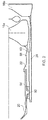
Figure 2 is a sectional side view of a splined shaft joint; -
Figure 3 is a closer view of the splined shaft join ofFigure 2 . - With reference to
Figure 1 , a gas turbine engine is generally indicated at 10, having a principal androtational axis 11. Theengine 10 comprises, in axial flow series, anair intake 12, apropulsive fan 13, a high-pressure compressor 14,combustion equipment 15, a high-pressure turbine 16, a low-pressure turbine 17 and anexhaust nozzle 18. A nacelle 3generally surrounds theengine 10 and defines theintake 12. All references to axially forward and axially rearward are with reference to the engine axis. - The
gas turbine engine 10 works in the conventional manner so that air entering theintake 12 is accelerated by thefan 13 to produce two air flows: a first air flow into the high-pressure compressor 14 and a second air flow which passes through abypass duct 21 to provide propulsive thrust. The high-pressure compressor 14 compresses the air flow directed into it before delivering that air to thecombustion equipment 15. - In the
combustion equipment 15 the air flow is mixed with fuel and the mixture combusted. The resultant hot combustion products then expand through, and thereby drive the high and low-pressure turbines 16, 17 before being exhausted through thenozzle 18 to provide additional propulsive thrust. The high 16 and low 17 pressure turbines drive respectively thehigh pressure compressor 14 and thefan 13, each by suitable interconnecting shaft. - The interconnecting shaft between the high pressure turbine and the high pressure compressor is formed in multiple parts connected through a splined joint. This joint is shown in more detail in
Figures 2 and3 . - The high pressure turbine has multiple stages each with an output shaft that extends axially forward of the turbine stage. The
compressor shaft 20, afirst turbine shaft 22 and asecond turbine shaft 24 are connected at a single joint location within the engine that is adjacent the turbine stages to minimise the length of each of the first and second turbine shafts. This position is marked by circle "A" inFigure 1 . Each of the shafts has a spline that engages with a spline on an adjacent shaft and each shaft has a different diameter, with theshaft 24 to thesecond turbine stage 16b having the smallest diameter, theshaft 22 to thefirst turbine stage 16a having an intermediate diameter and theshaft 20 to thecompressor stage 14 having the greatest diameter at the spline joint. - The hollow shaft to the second turbine stage has a constant internal diameter but a radial thickness that varies along its axial length. This is shown in more detail in
Figure 3 . At its axial forward end there is athinner portion 30 with a constant first thickness that after a length thickens to asecond thickness 32. Thetransition 34 between the first and second thickness is at a constant rate to aid manufacturability and the thinner portion aids assembly by providing a lead in for a locknut. - The second thickness has two regions of
screw threads spigot 50 from thecompressor shaft 20 may be located to be secured between the respective locknuts. The screw threads may be formed in the same or opposing directions but preferably are formed to prevent unwind of the locknuts during operation of the engine. -
Splines 38 are formed in the radially outer surface of the second turbine shaft axially rearward of the screw threads. Although axial splines may be used it is preferable to use helical splines that serve to better share load transfer. - The radial thickness expands downstream of the splines to provide a
shoulder 40 in the transition to a third radial thickness. The shoulder is sloped rather than stepped which allows the splines to continue into the region of the shoulder. - The
hollow shaft 22 to the first turbine stage has a profiled inner surface and a profiled outer surface. Both surfaces have regions having splines. At the axially forward end of the shaft, on the radially inner surface, there are a series ofsplines 42 that are configured to engage with the splines on the radially outer surface of the hollow shaft. The spline is formed on the radially inner surface of theshaft 22 through conventional manufacturing methods. The splines are complementary to the splines on the outer surface of the shaft to the second turbine stage. - The internal bore has a profile that has a radial diameter that increases to provide a
shoulder 44 that is configured to engage the shoulder provided by the increased thickness of the shaft to the second turbine. The profile of the internal bore accommodates the shaft to the second turbine stage such that there is contact along a significant, substantial and / or majority of the length of an axial overlap of the shaft to the first turbine stage and the shaft to the second turbine stage. - The outer surface of the shaft to the first turbine stage has a
second spline arrangement 46 on its radially outer surface for connection to acorresponding spline 52 on the radially inner surface of thecompressor shaft 20. These splines may extend axially, or helically as may be required for the optimum connection. - Downstream of the spline on the radially outer surface of the shaft to the first turbine stage there is provided a
local thickening 48 which is configured to provide anannular cavity 49, that may be cylindrical or conical and that is open at its axially forward end and which can receive the downstream end of the compressor shaft. The radial width of the cavity being selected to simultaneously radially constrain a portion of both the inner surface and the outer surface of shaft to the compressor. The cavity has an axial length of sufficient length that the compressor shaft does not extend right to the end. This ensures that the compressor shaft is axially constrained by locknuts acting on thespigot 50 rather than the end of the axial cavity. - The
hollow compressor shaft 20 is open at its axially rearward end and has a radially inwardly extendingflange 50 on its radially inner surface. The length of the flange configured to be sufficient to extend across the gap between the radially inner surface of the compressor shaft and the radially outer surface of theshaft 24 to the second turbine stage so that the flange abuts the radially outer surface of the shaft to the second turbine stage and acts as a radial location feature for the compressor shaft. - The flange is located axially forward of a
splined region 52 on the radially inner surface of the compressor shaft and which is configured to engage the splined region on the outer surface of the shaft to the first turbine stage. - The assembly and assembled splined joint will now be described in more detail.
- Firstly the two turbine shafts are assembled by inserting the
shaft 24 to the second turbine stage into the hollow bore of theshaft 22 to the first turbine stage. The second stage turbine shaft is input from the rear and moved axially till the spline on itsouter surface 38 engages thespline 42 on the inner surface of the first turbine stage shaft. If the splines are helically arranged either or both of the first or second shafts may need to be rotated about their longitudinal axes to ensure complete engagement of the splines. - The profile of the inner surface of the first turbine stage shaft and shoulder on the second turbine stage shaft abut to limit the relative axial movement of the two shafts. The radial outer surface of the second stage shaft the radially inner surface of the first stage shaft abut for a significant portion of their length where they overlap to limit their relative radial movement.
- As shown in
Figure 2 , at asuitable location 60, the radially inner surface of the first turbine shaft and the radially outer surface of the second turbine shaft may diverge either by changing the diameter or thickness of one or both shafts to enable the shaft to the second stage to pass the cob of thefirst turbine stage 16a. - Rearward of the spline joint the diameter and /or
thickness 68 of the shaft to the first turbine stage may be varied to ensure the drive is accurately transmitted from the turbine to the spline joint. - A
locknut 54 is threaded onto the outer surface of the shaft to the second turbine stage to secure the two shafts together as a unit and to inhibit relative axial movement and potential separation of the two shafts. - The turbine unit is subsequently secured to the compressor shaft by inserting a portion of the unit into the hollow bore of the compressor shaft. The insertion is to an axial point where the
flange 50 of the compressor shaft abuts an axially forward side of thelocknut 54 which secures the two turbine shafts together. The axially rearward end of the compressor shaft is inserted into the annular cavity provided on the outer surface of the first turbine shaft. - The splines on the radially inner surface of the compressor shaft and the radially outer surface of the first turbine shaft are engaged. The end of the compressor shaft does not abut the axially rearward face of the annular cavity such that that the relative axial location of the turbine unit and the compressor shaft is determined by the location of the flange and the locknut.
- The flange, in combination with the radially inner surface of the compressor shaft abutting the radially outer surface of the shaft to the first turbine stage, and in combination with the radially outer surface of the compressor shaft abutting the inner surface of the cavity 28 to ensure that the shafts are aligned without requiring the cost and complexity of using additional bearings. The structure is also resistant to bending moments and ensures the splines remain engaged at all times whilst being driven.
- A
second locknut 56 is inserted into the compressor shaft and the joined turbine shafts inserted before the locknut is tightened to capture theflange 30 between the two locknuts and the end of the compressor shaft in the cavity at the outside of the shaft to the first turbine stage. - It will be appreciated that the spline joint is axially and radially compact and has a low part count when compared with earlier configurations. The arrangement advantageously allows greater radial freedom to the join allowing it to be located closer to the axis of the engine and further away from the combustor where high temperature may increase the risk of fatigue of the components. The overall weight of the joint is reduced over conventional assemblies and this may improve the efficiency of the engine resulting in reduced fuel burn and the generation of environmentally harmful emissions. Furthermore the whole engine mechanical behaviour can be tuned hence the rotor system stiffness can be adjusted in a way to allow more favourable rotor frequency conditions.
- The join design helps with the development of smaller engine applications and opens up a different design space that may not be available by known technologies.
- The use of multiple axially spaced spigot joints help to ensure shaft straightness across the joint which reduces the need for additional support bearings.
- It will be understood that the invention is not limited to the embodiments above-described and various modifications and improvements can be made without departing from the concepts described herein. Except where mutually exclusive, any of the features may be employed separately or in combination with any other features and the disclosure extends to and includes all combinations and subcombinations of one or more features described herein.
- For example, the terms first and second turbine stages have been used but this could relate to their axial location rather than their numerical position. i.e. several turbine stages may be grouped within the first stage, and / or several turbine stages may be grouped within the second stage. Also, other turbine stages upstream of the first turbine stage may drive other shafts (not shown).
- The invention also finds application where three or more components are joined with each component having an axially extending shaft or flange that can be arranged coaxially. Such components may be rotor or disc sections that join together to form, for example, a turbine or compressor.
Claims (13)
- A gas turbine drive shaft arrangement, comprising:a hollow compressor drive shaft (20), a first hollow turbine drive shaft (22) for transferring torque from a first turbine stage and a second hollow turbine drive shaft (24) for transferring torque from a second turbine stage, wherein the compressor drive shaft has a spline on an internal surface that is meshed with a spline on an external surface of the first hollow turbine drive shaft, the first turbine drive shaft further comprising a spline on an internal surface thereof that is meshed with a spline on an external surface of the second hollow turbine drive shaft.
- A gas turbine drive shaft arrangement according to claim 1, wherein the first turbine shaft has an annular flange (48) extending from an exterior surface thereof, the annular flange defining an annular cavity that holds an end of the compressor shaft.
- A gas turbine drive shaft arrangement according to claim 1 or claim 2, wherein a projection (50) extends from a radially inner surface of the compressor shaft and abuts a radially outer surface portion of the second turbine shaft.
- A gas turbine drive shaft arrangement according to claim 3, wherein the projection is annular.
- A gas turbine drive shaft arrangement according to claim 3 or claim 4, wherein the projection is secured between two locknuts (54, 56) threadingly mounted to the second turbine shaft.
- A gas turbine drive shaft arrangement, according to any of claims 1 to 5, wherein the second turbine drive shaft (24) has a continuous shoulder (40) between a first outer surface portion and a second outer surface portion the diameter of the first outer surface portion being radially inside the second outer surface portion, the first turbine drive shaft having a continuous shoulder (44) between a first inner surface portion and a second inner surface portion the diameter of the first inner surface portion being radially inside the second inner surface portion,
- A gas turbine drive shaft arrangement according to claim 6, when dependent on claim 5, wherein one of the two locknuts abuts an end face of the first turbine drive shaft to inhibit axial movement between the first and second turbine drive shafts.
- A gas turbine drive shaft arrangement according to claim 7, wherein the continuous shoulder of the first turbine drive shaft abuts the continuous shoulder of the second turbine drive shaft.
- A gas turbine drive shaft according to any preceding claim, wherein the hollow compressor drive shaft, the first hollow turbine drive shaft for transferring torque from a first turbine stage and the second hollow turbine drive shaft are coaxial and overlap over at a portion of their length.
- A gas turbine drive shaft arrangement comprising:a first hollow turbine drive shaft (22) for transferring torque from a first turbine stage and a second hollow turbine drive shaft (24) for transferring torque from a second turbine stage, wherein the first turbine drive shaft comprising a spline on an internal surface thereof that is meshed with a spline on an external surface of the second hollow turbine drive shaft, wherein the second turbine drive shaft has a continuous shoulder (40) between a first outer surface portion and a second outer surface portion the diameter of the first outer surface portion being radially inside the second outer surface portion, the first turbine drive shaft having a continuous shoulder (44) between a first inner surface portion and a second inner surface portion the diameter of the first inner surface portion being radially inside the second inner surface portion.
- A gas turbine drive shaft arrangement according to claim 10, wherein the continuous shoulder of the first turbine drive shaft abuts the continuous shoulder of the second turbine drive shaft.
- A gas turbine drive shaft arrangement according to claim 11, wherein the continuous shoulder of the first turbine drive shaft abuts the continuous shoulder of the second turbine drive shaft.
- A gas turbine drive shaft arrangement according to any of claim 10 to claim 12, wherein the first turbine shaft has a flange extending from an exterior surface thereof, the annular flange defining an annular cavity that holds an end of a compressor shaft.
Applications Claiming Priority (1)
| Application Number | Priority Date | Filing Date | Title |
|---|---|---|---|
| GBGB1510256.9A GB201510256D0 (en) | 2015-06-12 | 2015-06-12 | Gas turbine arrangement |
Publications (2)
| Publication Number | Publication Date |
|---|---|
| EP3106612A1 true EP3106612A1 (en) | 2016-12-21 |
| EP3106612B1 EP3106612B1 (en) | 2018-11-14 |
Family
ID=53784561
Family Applications (1)
| Application Number | Title | Priority Date | Filing Date |
|---|---|---|---|
| EP16172903.3A Not-in-force EP3106612B1 (en) | 2015-06-12 | 2016-06-03 | Gas turbine arrangement |
Country Status (3)
| Country | Link |
|---|---|
| US (1) | US10392939B2 (en) |
| EP (1) | EP3106612B1 (en) |
| GB (1) | GB201510256D0 (en) |
Families Citing this family (4)
| Publication number | Priority date | Publication date | Assignee | Title |
|---|---|---|---|---|
| US11261753B2 (en) | 2017-12-06 | 2022-03-01 | General Electric Company | Method and device for connecting fan rotor to low pressure turbine rotor |
| US11460037B2 (en) | 2019-03-29 | 2022-10-04 | Pratt & Whitney Canada Corp. | Bearing housing |
| US11371513B2 (en) | 2020-03-04 | 2022-06-28 | Solar Turbined Incorporated | Integrated gas compressor |
| US11585277B2 (en) | 2020-09-17 | 2023-02-21 | Raytheon Technologies Corporation | Stiffened rotor shaft for a gas turbine engine |
Citations (5)
| Publication number | Priority date | Publication date | Assignee | Title |
|---|---|---|---|---|
| GB708018A (en) * | 1951-09-14 | 1954-04-28 | Rolls Royce | Improvements in or relating to shaft couplings |
| US3602535A (en) * | 1970-05-14 | 1971-08-31 | Gen Motors Corp | Shaft coupling |
| US3997962A (en) * | 1975-06-06 | 1976-12-21 | United Technologies Corporation | Method and tool for removing turbine from gas turbine twin spool engine |
| WO1995030098A1 (en) * | 1994-04-29 | 1995-11-09 | United Technologies Corporation | Gas turbine engine spline arrangement |
| US20130323077A1 (en) * | 2012-06-05 | 2013-12-05 | United Technologies Corporation | Compressor power and torque transmitting hub |
Family Cites Families (8)
| Publication number | Priority date | Publication date | Assignee | Title |
|---|---|---|---|---|
| US2977758A (en) * | 1955-02-18 | 1961-04-04 | Rolls Royce | Propeller driving gas-turbine engines |
| GB926947A (en) | 1961-11-27 | 1963-05-22 | Rolls Royce | Improvements relating to gas turbine engine casings |
| US3952391A (en) * | 1974-07-22 | 1976-04-27 | General Motors Corporation | Turbine blade with configured stalk |
| US4664599A (en) * | 1985-05-01 | 1987-05-12 | United Technologies Corporation | Two stage turbine rotor assembly |
| US4901523A (en) * | 1989-01-09 | 1990-02-20 | General Motors Corporation | Rotor for gas turbine engine |
| US4973221A (en) * | 1989-04-17 | 1990-11-27 | General Electric Company | Gas turbine engine motor assembly |
| FR2783579B1 (en) | 1998-09-17 | 2000-11-03 | Snecma | RETAINING ARRANGEMENT FOR A BEARING, IN PARTICULAR FOR A HIGH PRESSURE COMPRESSOR SHAFT |
| GB0818249D0 (en) | 2008-10-07 | 2008-11-12 | Rolls Royce Plc | Splined couplings |
-
2015
- 2015-06-12 GB GBGB1510256.9A patent/GB201510256D0/en not_active Ceased
-
2016
- 2016-06-03 EP EP16172903.3A patent/EP3106612B1/en not_active Not-in-force
- 2016-06-06 US US15/174,777 patent/US10392939B2/en active Active
Patent Citations (5)
| Publication number | Priority date | Publication date | Assignee | Title |
|---|---|---|---|---|
| GB708018A (en) * | 1951-09-14 | 1954-04-28 | Rolls Royce | Improvements in or relating to shaft couplings |
| US3602535A (en) * | 1970-05-14 | 1971-08-31 | Gen Motors Corp | Shaft coupling |
| US3997962A (en) * | 1975-06-06 | 1976-12-21 | United Technologies Corporation | Method and tool for removing turbine from gas turbine twin spool engine |
| WO1995030098A1 (en) * | 1994-04-29 | 1995-11-09 | United Technologies Corporation | Gas turbine engine spline arrangement |
| US20130323077A1 (en) * | 2012-06-05 | 2013-12-05 | United Technologies Corporation | Compressor power and torque transmitting hub |
Also Published As
| Publication number | Publication date |
|---|---|
| EP3106612B1 (en) | 2018-11-14 |
| GB201510256D0 (en) | 2015-07-29 |
| US10392939B2 (en) | 2019-08-27 |
| US20160363171A1 (en) | 2016-12-15 |
Similar Documents
| Publication | Publication Date | Title |
|---|---|---|
| US11181046B1 (en) | High speed shaft flexible coupling | |
| EP2935839B1 (en) | Turbine engine gearbox mount with multiple fuse joints | |
| EP3029358B1 (en) | Lightweight and compliant journal pin | |
| US9500133B2 (en) | Mount with an axial upstream linkage for connecting a gearbox to a turbine engine case | |
| US10267365B2 (en) | Power gearbox pin arrangement | |
| EP3354876B1 (en) | Gas turbine engine architecture with split compressor system | |
| US20180334964A1 (en) | Support assembly for a propeller shaft | |
| CA2602322C (en) | Gas turbine engine assembly and method of assembling same | |
| EP3106612B1 (en) | Gas turbine arrangement | |
| US10094335B2 (en) | Compliant shaft with a recursive configuration for turbine engines | |
| EP3514325A1 (en) | Fan disc assembly | |
| US20190055991A1 (en) | Mechanical fuse device and method for operating a mechanical fuse device | |
| US10451003B2 (en) | Nozzle support system | |
| US20180179950A1 (en) | Turbine engine assembly including a rotating detonation combustor | |
| EP3260739B1 (en) | Low-cost epicyclic gear carrier and method of making the same | |
| EP3032070B1 (en) | Bearing load sharing system | |
| EP3524776B1 (en) | Fan disc assembly | |
| US10502144B2 (en) | Gas turbine engine with a geared turbofan arrangement | |
| US9951688B2 (en) | Low pressure shaft | |
| EP3112634B1 (en) | Advanced distributed engine architecture-design alternative | |
| EP3453846B1 (en) | Ventilated bush | |
| US20150369131A1 (en) | Axial tension system for a gas turbine engine case |
Legal Events
| Date | Code | Title | Description |
|---|---|---|---|
| PUAI | Public reference made under article 153(3) epc to a published international application that has entered the european phase |
Free format text: ORIGINAL CODE: 0009012 |
|
| STAA | Information on the status of an ep patent application or granted ep patent |
Free format text: STATUS: THE APPLICATION HAS BEEN PUBLISHED |
|
| AK | Designated contracting states |
Kind code of ref document: A1 Designated state(s): AL AT BE BG CH CY CZ DE DK EE ES FI FR GB GR HR HU IE IS IT LI LT LU LV MC MK MT NL NO PL PT RO RS SE SI SK SM TR |
|
| AX | Request for extension of the european patent |
Extension state: BA ME |
|
| STAA | Information on the status of an ep patent application or granted ep patent |
Free format text: STATUS: REQUEST FOR EXAMINATION WAS MADE |
|
| 17P | Request for examination filed |
Effective date: 20170615 |
|
| RBV | Designated contracting states (corrected) |
Designated state(s): AL AT BE BG CH CY CZ DE DK EE ES FI FR GB GR HR HU IE IS IT LI LT LU LV MC MK MT NL NO PL PT RO RS SE SI SK SM TR |
|
| GRAP | Despatch of communication of intention to grant a patent |
Free format text: ORIGINAL CODE: EPIDOSNIGR1 |
|
| STAA | Information on the status of an ep patent application or granted ep patent |
Free format text: STATUS: GRANT OF PATENT IS INTENDED |
|
| INTG | Intention to grant announced |
Effective date: 20180522 |
|
| GRAS | Grant fee paid |
Free format text: ORIGINAL CODE: EPIDOSNIGR3 |
|
| GRAA | (expected) grant |
Free format text: ORIGINAL CODE: 0009210 |
|
| STAA | Information on the status of an ep patent application or granted ep patent |
Free format text: STATUS: THE PATENT HAS BEEN GRANTED |
|
| AK | Designated contracting states |
Kind code of ref document: B1 Designated state(s): AL AT BE BG CH CY CZ DE DK EE ES FI FR GB GR HR HU IE IS IT LI LT LU LV MC MK MT NL NO PL PT RO RS SE SI SK SM TR |
|
| REG | Reference to a national code |
Ref country code: CH Ref legal event code: EP Ref country code: AT Ref legal event code: REF Ref document number: 1065056 Country of ref document: AT Kind code of ref document: T Effective date: 20181115 |
|
| REG | Reference to a national code |
Ref country code: IE Ref legal event code: FG4D |
|
| REG | Reference to a national code |
Ref country code: DE Ref legal event code: R096 Ref document number: 602016007072 Country of ref document: DE |
|
| REG | Reference to a national code |
Ref country code: NL Ref legal event code: MP Effective date: 20181114 |
|
| REG | Reference to a national code |
Ref country code: LT Ref legal event code: MG4D |
|
| REG | Reference to a national code |
Ref country code: AT Ref legal event code: MK05 Ref document number: 1065056 Country of ref document: AT Kind code of ref document: T Effective date: 20181114 |
|
| PG25 | Lapsed in a contracting state [announced via postgrant information from national office to epo] |
Ref country code: IS Free format text: LAPSE BECAUSE OF FAILURE TO SUBMIT A TRANSLATION OF THE DESCRIPTION OR TO PAY THE FEE WITHIN THE PRESCRIBED TIME-LIMIT Effective date: 20190314 Ref country code: FI Free format text: LAPSE BECAUSE OF FAILURE TO SUBMIT A TRANSLATION OF THE DESCRIPTION OR TO PAY THE FEE WITHIN THE PRESCRIBED TIME-LIMIT Effective date: 20181114 Ref country code: AT Free format text: LAPSE BECAUSE OF FAILURE TO SUBMIT A TRANSLATION OF THE DESCRIPTION OR TO PAY THE FEE WITHIN THE PRESCRIBED TIME-LIMIT Effective date: 20181114 Ref country code: HR Free format text: LAPSE BECAUSE OF FAILURE TO SUBMIT A TRANSLATION OF THE DESCRIPTION OR TO PAY THE FEE WITHIN THE PRESCRIBED TIME-LIMIT Effective date: 20181114 Ref country code: LT Free format text: LAPSE BECAUSE OF FAILURE TO SUBMIT A TRANSLATION OF THE DESCRIPTION OR TO PAY THE FEE WITHIN THE PRESCRIBED TIME-LIMIT Effective date: 20181114 Ref country code: NO Free format text: LAPSE BECAUSE OF FAILURE TO SUBMIT A TRANSLATION OF THE DESCRIPTION OR TO PAY THE FEE WITHIN THE PRESCRIBED TIME-LIMIT Effective date: 20190214 Ref country code: LV Free format text: LAPSE BECAUSE OF FAILURE TO SUBMIT A TRANSLATION OF THE DESCRIPTION OR TO PAY THE FEE WITHIN THE PRESCRIBED TIME-LIMIT Effective date: 20181114 Ref country code: ES Free format text: LAPSE BECAUSE OF FAILURE TO SUBMIT A TRANSLATION OF THE DESCRIPTION OR TO PAY THE FEE WITHIN THE PRESCRIBED TIME-LIMIT Effective date: 20181114 Ref country code: BG Free format text: LAPSE BECAUSE OF FAILURE TO SUBMIT A TRANSLATION OF THE DESCRIPTION OR TO PAY THE FEE WITHIN THE PRESCRIBED TIME-LIMIT Effective date: 20190214 |
|
| PG25 | Lapsed in a contracting state [announced via postgrant information from national office to epo] |
Ref country code: AL Free format text: LAPSE BECAUSE OF FAILURE TO SUBMIT A TRANSLATION OF THE DESCRIPTION OR TO PAY THE FEE WITHIN THE PRESCRIBED TIME-LIMIT Effective date: 20181114 Ref country code: PT Free format text: LAPSE BECAUSE OF FAILURE TO SUBMIT A TRANSLATION OF THE DESCRIPTION OR TO PAY THE FEE WITHIN THE PRESCRIBED TIME-LIMIT Effective date: 20190314 Ref country code: SE Free format text: LAPSE BECAUSE OF FAILURE TO SUBMIT A TRANSLATION OF THE DESCRIPTION OR TO PAY THE FEE WITHIN THE PRESCRIBED TIME-LIMIT Effective date: 20181114 Ref country code: NL Free format text: LAPSE BECAUSE OF FAILURE TO SUBMIT A TRANSLATION OF THE DESCRIPTION OR TO PAY THE FEE WITHIN THE PRESCRIBED TIME-LIMIT Effective date: 20181114 Ref country code: GR Free format text: LAPSE BECAUSE OF FAILURE TO SUBMIT A TRANSLATION OF THE DESCRIPTION OR TO PAY THE FEE WITHIN THE PRESCRIBED TIME-LIMIT Effective date: 20190215 Ref country code: RS Free format text: LAPSE BECAUSE OF FAILURE TO SUBMIT A TRANSLATION OF THE DESCRIPTION OR TO PAY THE FEE WITHIN THE PRESCRIBED TIME-LIMIT Effective date: 20181114 |
|
| PG25 | Lapsed in a contracting state [announced via postgrant information from national office to epo] |
Ref country code: CZ Free format text: LAPSE BECAUSE OF FAILURE TO SUBMIT A TRANSLATION OF THE DESCRIPTION OR TO PAY THE FEE WITHIN THE PRESCRIBED TIME-LIMIT Effective date: 20181114 Ref country code: PL Free format text: LAPSE BECAUSE OF FAILURE TO SUBMIT A TRANSLATION OF THE DESCRIPTION OR TO PAY THE FEE WITHIN THE PRESCRIBED TIME-LIMIT Effective date: 20181114 Ref country code: IT Free format text: LAPSE BECAUSE OF FAILURE TO SUBMIT A TRANSLATION OF THE DESCRIPTION OR TO PAY THE FEE WITHIN THE PRESCRIBED TIME-LIMIT Effective date: 20181114 Ref country code: DK Free format text: LAPSE BECAUSE OF FAILURE TO SUBMIT A TRANSLATION OF THE DESCRIPTION OR TO PAY THE FEE WITHIN THE PRESCRIBED TIME-LIMIT Effective date: 20181114 |
|
| REG | Reference to a national code |
Ref country code: DE Ref legal event code: R097 Ref document number: 602016007072 Country of ref document: DE |
|
| PG25 | Lapsed in a contracting state [announced via postgrant information from national office to epo] |
Ref country code: EE Free format text: LAPSE BECAUSE OF FAILURE TO SUBMIT A TRANSLATION OF THE DESCRIPTION OR TO PAY THE FEE WITHIN THE PRESCRIBED TIME-LIMIT Effective date: 20181114 Ref country code: SM Free format text: LAPSE BECAUSE OF FAILURE TO SUBMIT A TRANSLATION OF THE DESCRIPTION OR TO PAY THE FEE WITHIN THE PRESCRIBED TIME-LIMIT Effective date: 20181114 Ref country code: RO Free format text: LAPSE BECAUSE OF FAILURE TO SUBMIT A TRANSLATION OF THE DESCRIPTION OR TO PAY THE FEE WITHIN THE PRESCRIBED TIME-LIMIT Effective date: 20181114 Ref country code: SK Free format text: LAPSE BECAUSE OF FAILURE TO SUBMIT A TRANSLATION OF THE DESCRIPTION OR TO PAY THE FEE WITHIN THE PRESCRIBED TIME-LIMIT Effective date: 20181114 |
|
| PLBE | No opposition filed within time limit |
Free format text: ORIGINAL CODE: 0009261 |
|
| STAA | Information on the status of an ep patent application or granted ep patent |
Free format text: STATUS: NO OPPOSITION FILED WITHIN TIME LIMIT |
|
| 26N | No opposition filed |
Effective date: 20190815 |
|
| PG25 | Lapsed in a contracting state [announced via postgrant information from national office to epo] |
Ref country code: SI Free format text: LAPSE BECAUSE OF FAILURE TO SUBMIT A TRANSLATION OF THE DESCRIPTION OR TO PAY THE FEE WITHIN THE PRESCRIBED TIME-LIMIT Effective date: 20181114 |
|
| PGFP | Annual fee paid to national office [announced via postgrant information from national office to epo] |
Ref country code: DE Payment date: 20190627 Year of fee payment: 4 |
|
| PG25 | Lapsed in a contracting state [announced via postgrant information from national office to epo] |
Ref country code: MC Free format text: LAPSE BECAUSE OF FAILURE TO SUBMIT A TRANSLATION OF THE DESCRIPTION OR TO PAY THE FEE WITHIN THE PRESCRIBED TIME-LIMIT Effective date: 20181114 |
|
| REG | Reference to a national code |
Ref country code: CH Ref legal event code: PL |
|
| REG | Reference to a national code |
Ref country code: BE Ref legal event code: MM Effective date: 20190630 |
|
| PG25 | Lapsed in a contracting state [announced via postgrant information from national office to epo] |
Ref country code: TR Free format text: LAPSE BECAUSE OF FAILURE TO SUBMIT A TRANSLATION OF THE DESCRIPTION OR TO PAY THE FEE WITHIN THE PRESCRIBED TIME-LIMIT Effective date: 20181114 |
|
| PG25 | Lapsed in a contracting state [announced via postgrant information from national office to epo] |
Ref country code: IE Free format text: LAPSE BECAUSE OF NON-PAYMENT OF DUE FEES Effective date: 20190603 |
|
| PG25 | Lapsed in a contracting state [announced via postgrant information from national office to epo] |
Ref country code: BE Free format text: LAPSE BECAUSE OF NON-PAYMENT OF DUE FEES Effective date: 20190630 Ref country code: LI Free format text: LAPSE BECAUSE OF NON-PAYMENT OF DUE FEES Effective date: 20190630 Ref country code: LU Free format text: LAPSE BECAUSE OF NON-PAYMENT OF DUE FEES Effective date: 20190603 Ref country code: CH Free format text: LAPSE BECAUSE OF NON-PAYMENT OF DUE FEES Effective date: 20190630 |
|
| PGFP | Annual fee paid to national office [announced via postgrant information from national office to epo] |
Ref country code: FR Payment date: 20200626 Year of fee payment: 5 |
|
| PGFP | Annual fee paid to national office [announced via postgrant information from national office to epo] |
Ref country code: GB Payment date: 20200630 Year of fee payment: 5 |
|
| REG | Reference to a national code |
Ref country code: DE Ref legal event code: R119 Ref document number: 602016007072 Country of ref document: DE |
|
| PG25 | Lapsed in a contracting state [announced via postgrant information from national office to epo] |
Ref country code: CY Free format text: LAPSE BECAUSE OF FAILURE TO SUBMIT A TRANSLATION OF THE DESCRIPTION OR TO PAY THE FEE WITHIN THE PRESCRIBED TIME-LIMIT Effective date: 20181114 Ref country code: DE Free format text: LAPSE BECAUSE OF NON-PAYMENT OF DUE FEES Effective date: 20210101 |
|
| PG25 | Lapsed in a contracting state [announced via postgrant information from national office to epo] |
Ref country code: MT Free format text: LAPSE BECAUSE OF FAILURE TO SUBMIT A TRANSLATION OF THE DESCRIPTION OR TO PAY THE FEE WITHIN THE PRESCRIBED TIME-LIMIT Effective date: 20181114 Ref country code: HU Free format text: LAPSE BECAUSE OF FAILURE TO SUBMIT A TRANSLATION OF THE DESCRIPTION OR TO PAY THE FEE WITHIN THE PRESCRIBED TIME-LIMIT; INVALID AB INITIO Effective date: 20160603 |
|
| GBPC | Gb: european patent ceased through non-payment of renewal fee |
Effective date: 20210603 |
|
| PG25 | Lapsed in a contracting state [announced via postgrant information from national office to epo] |
Ref country code: GB Free format text: LAPSE BECAUSE OF NON-PAYMENT OF DUE FEES Effective date: 20210603 |
|
| PG25 | Lapsed in a contracting state [announced via postgrant information from national office to epo] |
Ref country code: FR Free format text: LAPSE BECAUSE OF NON-PAYMENT OF DUE FEES Effective date: 20210630 |
|
| PG25 | Lapsed in a contracting state [announced via postgrant information from national office to epo] |
Ref country code: MK Free format text: LAPSE BECAUSE OF FAILURE TO SUBMIT A TRANSLATION OF THE DESCRIPTION OR TO PAY THE FEE WITHIN THE PRESCRIBED TIME-LIMIT Effective date: 20181114 |