EP3106356A1 - Electronic steering column lock system - Google Patents
Electronic steering column lock system Download PDFInfo
- Publication number
- EP3106356A1 EP3106356A1 EP15465524.5A EP15465524A EP3106356A1 EP 3106356 A1 EP3106356 A1 EP 3106356A1 EP 15465524 A EP15465524 A EP 15465524A EP 3106356 A1 EP3106356 A1 EP 3106356A1
- Authority
- EP
- European Patent Office
- Prior art keywords
- type
- disk
- shaft
- disks
- steering column
- Prior art date
- Legal status (The legal status is an assumption and is not a legal conclusion. Google has not performed a legal analysis and makes no representation as to the accuracy of the status listed.)
- Granted
Links
Images


Classifications
-
- B—PERFORMING OPERATIONS; TRANSPORTING
- B60—VEHICLES IN GENERAL
- B60R—VEHICLES, VEHICLE FITTINGS, OR VEHICLE PARTS, NOT OTHERWISE PROVIDED FOR
- B60R25/00—Fittings or systems for preventing or indicating unauthorised use or theft of vehicles
- B60R25/01—Fittings or systems for preventing or indicating unauthorised use or theft of vehicles operating on vehicle systems or fittings, e.g. on doors, seats or windscreens
- B60R25/02—Fittings or systems for preventing or indicating unauthorised use or theft of vehicles operating on vehicle systems or fittings, e.g. on doors, seats or windscreens operating on the steering mechanism
- B60R25/021—Fittings or systems for preventing or indicating unauthorised use or theft of vehicles operating on vehicle systems or fittings, e.g. on doors, seats or windscreens operating on the steering mechanism restraining movement of the steering column or steering wheel hub, e.g. restraining means controlled by ignition switch
- B60R25/0215—Fittings or systems for preventing or indicating unauthorised use or theft of vehicles operating on vehicle systems or fittings, e.g. on doors, seats or windscreens operating on the steering mechanism restraining movement of the steering column or steering wheel hub, e.g. restraining means controlled by ignition switch using electric means, e.g. electric motors or solenoids
-
- F—MECHANICAL ENGINEERING; LIGHTING; HEATING; WEAPONS; BLASTING
- F16—ENGINEERING ELEMENTS AND UNITS; GENERAL MEASURES FOR PRODUCING AND MAINTAINING EFFECTIVE FUNCTIONING OF MACHINES OR INSTALLATIONS; THERMAL INSULATION IN GENERAL
- F16D—COUPLINGS FOR TRANSMITTING ROTATION; CLUTCHES; BRAKES
- F16D57/00—Liquid-resistance brakes; Brakes using the internal friction of fluids or fluid-like media, e.g. powders
- F16D57/002—Liquid-resistance brakes; Brakes using the internal friction of fluids or fluid-like media, e.g. powders comprising a medium with electrically or magnetically controlled internal friction, e.g. electrorheological fluid, magnetic powder
Definitions
- the present invention relates to an electronic steering column lock system (ESCL-System).
- ESL-System electronic steering column lock system
- Such systems for example can be used to selectively lock or unlock a steering wheel of a vehicle (for example a car) or the like.
- ESCL-systems usually comprise an actuator (e.g. a motor) that moves a pin into holes in the steering column in order to lock it as an anti-theft measure or removes the pin from the holes in order to unlock it so that the steering wheel can be freely moved for steering the vehicle.
- actuator e.g. a motor
- An usual system is disclosed by US 7, 327, 050 B2 .
- Such known ESCL-systems allow only two states: locked and unlocked.
- One object of the present invention is to provide an improved electronic steering column lock system.
- one object of the present invention is to provide an electronic steering column lock system which is configured to enable adding of other functionalities to said system.
- the present invention provides an electronic steering column lock system comprising: a shaft, said shaft being a steering column shaft or said shaft being configured to be coupled to a steering column shaft, a housing, an electromagnet, being disposed at a fixed position inside the housing, at least one disk of a first type being rotatory form locked to the housing with regard to the centerline of the shaft, at least one disk of a second type being rotatory form locked to the shaft with regard to the centerline of the shaft, the at least one disk of the first type and the at least one disk of the second type being disposed adjacent to each other on a same side of the electromagnet inside the housing, wherein a surface of the at least one disk of the first type and a surface of the at least one disk of the second type are facing each other, wherein the form (i.
- said surface of the at least one disk of the first type and the form (i. e. the shape) of the surface of said at least one disk of the second type are designed so that spacings remain between both of said surfaces if said surface of the disk of said first type and said surface of said disk of the second type are in contact to each other, said at least one disk of the first type and said at least one disk of the second type being made from ferromagnetic material or comprising ferromagnetic material, magnetorheological fluid being kept in the housing, and the at least one disk of the first type and the at least one disk of the second type are immersed, in particular are completely immersed, in the magnetorheological fluid.
- the housing is considered to be stationary (for example it may be fixed inside a vehicle, for example at its dashboard. Because at least one disk is rotatory form locked to the housing and because at least one another disk is rotatory form locked to the shaft, said disks will move relatively to each other when the shaft is turned around its centerline (i. e. about its geometrical axis of rotation).
- the coil i. e.
- a magnetic field will be generated that will produce two effects: a first effect is that the said disks will be attracted by the core and hence will come closer to each other (for example by sliding in a direction parallel to the centerline of the shaft and/or, depending of the embodiment, by deforming) which will generate friction between the adjacent disks at its contact areas.
- the second effect due to activating the coil is that the magnetorheological fluid will be also activated and thus through the shearing effect will also generate a force between the disks resulting in a turning moment that will oppose the rotation of the shaft relative to the housing of the system. Accordingly, both effects will reinforce the friction between adjacent disks so that it appears a braking effect on the steering columns shaft.
- high frequency braking pulses can be applied, generating haptic responses in a steering wheel which is coupled to the electronic steering column lock system.
- the high frequency braking pulses can be applied without wearing the disks which is an advantage of the invention.
- the braking pulses can be applied without direct contact between adjacent disks.
- the locking system is activated only in load. Hence it can be programmed to activate itself upon unauthorized (without a key) entry in the car or at starting a car or the like. Thus difficulties in unlocking the steering column due to wheel positioning during parking are avoided.
- a further advantage of the invention is that it provides a possibility to add other functions based on the ones above.
- the invention provides the possibility to generate more rigidity in a steering wheel which is coupled to the electronic steering column lock system of the invention at high speeds.
- the electronic steering column lock system may comprise a control unit for controlling the applied voltage subject to a variable (for example the speed of a vehicle) which may be sensed by an external sensor coupled to the control unit.
- a haptic response in the steering wheel may be provided by the system by an input from other sensors, for example to make the driver aware of different road conditions or dangers.
- the invention comes to offer greater flexibility to the electronic steering column lock system (ESCL system), allowing other functionalities to be added to the system.
- ESL system electronic steering column lock system
- the invention provides a smart electronic steering column lock system using magnetorheological fluid.
- magnetorheological fluid of the electronic steering column lock system of the invention may be a ferromagnetic fluid or another appropriate magnetorheological fluid.
- at least some of said spacings or all of said spacings between adjacent disks include and in particular are filled by magnetorheological fluid.
- disk of a first type and disk of a second type are used to distinguish disks which are rotatory form locked to housing from disks which are rotatory form locked to the shaft. It is preferred that disks of the first type are different from disks of the second type, however as an alternative, depending of the embodiment, disks of the first type may be identical to disks of the second type.
- the electronic steering column lock system comprises multiple disks of the first type, respectively being rotatory form locked to the housing with regard to the centerline of the shaft, and it comprises multiple disks of the second type, respectively being rotatory form locked to the shaft with regard to the centerline of the shaft, herein a first set comprising disks of the first type and a second set comprising disks of the second type are disposed on the same side of the electromagnet, wherein said disks of the first set and said disks of the second set being disposed alternating to each other, wherein the remaining disks of the first type (as a third set) and the remaining disks of the second type (as a fourth set) are disposed alternating to each other on the other side of the electromagnet, wherein with regard to each respective neighboring pair of disks comprising a disk of the first type and a disk of the second type it is provided:
- each disk of the first type is slidable relative to the housing parallel to the centerline of the shaft, respectively, and each disk of the second type is slidable relative to the shaft parallel to the centerline of the shaft, respectively.
- Such embodiment facilitates that adjacent disks come to each other for direct contact in response to an activation of the coil. This provides the possibility that the disks can move freely along their axis.
- each disk of the first type and each disk of a second type comprises a central opening, respectively, wherein the shaft being axially extended through said respective central openings.
- all disks have a corresponding outer diameter and/or a corresponding inner diameter.
- said housing provides two rotary feedthroughs for the shaft, said feedthroughs being spaced apart from each other in a direction parallel to the centerline of the shaft, the shaft being fed through both of the feedthroughs.
- each disk of the first type and the major extension of each disk of the second type is perpendicular to the centerline of the shaft.
- the respective planes of the disks which are defined by the main extension of its respective disk extend parallel or at least substantially parallel to each other.
- the electromagnet comprises a ferromagnetic core and a coil.
- the shaft may be made from nonmagnetic material, like for example synthetic material (e. g. plastic or the like). If the steering column shaft is mad from nonmagnetic material, upon activating the coil most of the magnetic field inside the activated coil will be directed through the coils core, the disks and may be closed through an outer casing (for example comprising a surrounding side wall and respective lids) that may be made from ferromagnetic material. This will cause an increase in apparent viscosity on direction parallel to the shaft and perpendicular to the rotation plane of the disks.
- nonmagnetic material like for example synthetic material (e. g. plastic or the like).
- the ferromagnetic disks may be made of steel or the like.
- the housing has an inner wall surrounding said disks, at least one notch or a number of notches are formed at an inner surface of the housing, each notch respectively extending parallel to the centerline of the shaft, each of the disks of the first type at its respective outer edge comprises at least one radial protrusion or a number of radial protrusion, wherein each individual of said disks protrusions are engaged in one of the notches for providing a rotatory form lock of said respective disks to the housing with regard to the centerline of the shaft, at least one at least one notch or a number of notches is/are formed at an outer surface of the shaft, each notch respectively extending parallel to the centerline of the shaft, each of the disks of the second type at its respective inner edge comprises at least one radial protrusion or a number of radial protrusion, wherein each individual of said disks protrusions is engaged in one of the notches for providing a rotatory form lock of said respective disks to the shaft with regard to
- the housing comprises an outer casing, in particular comprising a surrounding side wall, a bottom wall and an upper wall and that, the outer casing comprises ferromagnetic material or consists of ferromagnetic material.
- the components of the casing for example may be formed from steel or the like.
- the housing comprises a shell being fixed inside said outer casing, wherein said shell comprises nonmagnetic material or consists of nonmagnetic material and/or said shell comprises insulating material or consists of insulating material, wherein in particular the axial notch or the axial notches being formed at an inner surface of the shell.
- the electromagnet is sealed off from the outer casing. It is also preferred that by the shell the electromagnet is sealed from the magnetorheological fluid.
- the electromagnet may be encapsulated in the nonmagnetic insulating material.
- each disk at its both opposite surfaces has a pattern comprising circular grooves and circular protrusions alternating each other, the circular grooves and the circular protrusions may extend concentrically with regard to the centerline of the shaft, wherein at each radius where at the one of the said both surfaces a groove is extending at the other of said both surfaces a protrusion is extending and vice versa, respectively.
- a curvature of the grooves at its respective apex has a radius which is less compared to a radius of a curvature of the protrusions at its respective apex and wherein in particular at each of said surfaces the alternating grooves and protrusions forming a wavelike profile in section planes including the centerline of the shaft.
- the disks are stacked with regard to each respective neighboring pair of disks comprising a disk of the first type and a disk of the second type so that: protrusions of said disk of the first type and grooves of said disk of the second type are engaging each other and are bordering a, in particular circular, spacing including magnetorheological fluid, and protrusions of said disk of the second type and grooves of said disk of the first type are engaging each other and are bordering a, in particular circular, spacing including magnetorheological fluid.
- the housing may be fixed or may be configured to be fixed to a vehicle, for example to a dashboard of a car or the like.
- the electronic steering column lock system comprises a power supply unit and a control unit which may be coupled to the power supply unit and to the electromagnet.
- the control unit may be configured to provide an electrical voltage being controlled by the control unit to the electromagnet.
- the electronic steering column lock system may comprise an external sensor configured to sense a variable.
- the control unit may be configured for controlling the electrical voltage subject to a signal provided by the external sensor.
- an electronic steering column lock system 1 With reference to Figures 1 - 5 it is described by way of example an embodiment of an electronic steering column lock system 1 according to the invention. It comprises a nonmagnetic shaft 2 (shown only partially) which in the example is a steering column shaft of a vehicle or the like and which may be connected to a steering wheel (not shown in the Figures).
- the electronic steering column lock system comprises an electromagnet 3 consisting of a ferromagnetic core 4 and a coil 5 surrounding the core 4.
- a central opening 6 is formed in the core 4 wherein said opening 6 has a diameter corresponding to the diameter of the shaft 2 so that the shaft 2 can be fed through the core 4.
- Electronic steering column lock system 1 comprises a housing 7 having a ferromagnetic outer casing 8 and a nonmagnetic shell 9 fixed inside said casing 8.
- the outer casing 8 comprises a surrounding sidewall 10, a bottom wall 11 and an upper wall 12 whereat walls 11, 12 have the function of lids which can be fixed by screws 13 at the bottom and at the top of the circular side wall 10 after mounting further components inside the casing 8.
- the electronic steering column lock system 1 comprises four ferromagnetic disks 14 of a first type and four ferromagnetic disks 15 of a second type.
- Each of the disks 14, 15 comprises a central opening 16 having a diameter matching the diameter of the shaft 2.
- Each disk 14 of the first type at its respective outer edge comprises four protrusions 17 protruding from the circular outer edge in the respective outer radial direction. Protrusions 17 are distributed in equal distances along the circumference.
- Each of the disks 15 of the second type at its respective edge of its opening 16 comprises four protrusions 18 protruding from the edge in a respective inwardly radial direction. Also the inner protrusions 18 are distributed along the circumference in equal distances to each other.
- Shell 9 is made from a sleeve having an outer diameter which matches the inner diameter of the surrounding side wall 10 and which corresponds in its height to the side wall 10, too.
- Shell 9 may be fixed within casing 8 for example by fixing the walls 11, 12 at the side wall 10.
- shell 9 may be stacked within side wall 10 or clamped within side wall 10 if having a diameter which is appropriate to provide a press fit.
- Shell 9 has a central opening 19 which is surrounded by its 20.
- Inner surface 21 of wall 20 extends along the circumference. In an upper and in a lower section of surface 21 its diameter matches the outer diameter of the disks 14, 15.
- four notches 22 extending axially, i. e. parallel to a centerline 23 of the shaft 2.
- Shell 9 comprises a circular protrusion 24 protruding radial inwardly from the inner surface 21 between its lower and upper sections. Within protrusion 24 a circular groove is formed. The outer diameter of groove 25 matches the outer diameter of coil 5.
- a number of notches 26 are formed in the cylindrical surface of shaft 2.
- the notches 26 are spaced from each other along the circumference and extend parallel to the centerline 23.
- each individual of said disks 15 protrusions 18 is engaged in one of the notches 26 for providing a rotatory form lock of the respective disk 15 to the shaft 2 with regard to the centerline 23 of the shaft 2.
- the disks 14 are connected to the housing 7 by protrusions 17 and notches 22 in a manner such that they are slidable relative to the housing 7 parallel to the centerline 23 such that they are not rotatable relative to the housing around the centerline 23.
- disks 15 are coupled to the shaft 2 by means of protrusions 18 and notches 26 such that they are slidable relative to the shaft 2 parallel to the centerline 23 however such that they are not rotatable around shaft 2 with regard to its centerline 23.
- disks 15 are flexible so that they can be elastically deformed for inserting its protrusions 18 in notches 26.
- axial protrusions may be formed at the shaft 2 and recesses may be formed at the inner edge of disks 15 for providing a rotatory form closure.
- the disks 14 it is also possible to replace its protrusions 17 by recesses and to form mating axial protrusions at the inner surface 21 for engaging to provide a rotatory form lock.
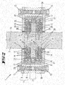
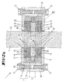
- Figures 2, 2a and 4 show the electronic steering column lock system 1 after mounting the components shown by Figure 1 .
- Disks 14 and disks 15 are disposed alternating to each other.
- a first set comprising two disks 14 of the first type and a second set comprising two disks 15 of the second type are disposed on the upper side of the electromagnet 3 wherein disks 14 and disks 15 alternate.
- a third set comprising two disks 14 and a fourth set comprising two disks 15 are both disposed on the lower side of the electromagnet 3 wherein said disks 14 and said disks 15 alternate to each other.
- Shaft 2 is fed through the opening 6 and through openings 16 and 19 as well through central openings 27 formed in the walls 11, 12.
- each opening 27 is formed a circular groove for inserting a gasket (O-ring) 28. Openings 27 provide two rotary sealed feedthroughs 35 for the shaft 2. The feedthroughs 35 allow rotation of shaft 2 about centerline 23 relative to the housing 7. Within the inner chamber of housing 7 a magnetorheological fluid 30 is kept. The disks 14, 15 are completely immersed in said magnetorheological fluid 30.
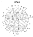
- each respective neighboring pair of disks comprising a disk 14 of the first type and a disk 15 of the second type it is provided that a surface 31 of disk 14 and a surface 32 of disk 15 are facing each other.
- the form of said surfaces 31 and the form of the surfaces 32 are designed so that spacings 33 which are spaced apart from each other remain between each pair of disks 14, 15 if a disk 14 and a disk 15 are brought together in contact.
- spacings 33 remain also if the said disks 14, 15 are pressed together in a direction parallel to the centerline 23.
- areas of contact are designated by reference numeral 34. Spacings 33 are filled by the magnetorheological fluid 30.
- Figure 5 refers to the locked state of the system
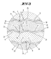
- Figure 3 relates to the unlocked state wherein the disks 14, 15 are discharged so that (compared to Figure 5 ) no areas of contact 34 or only slight contact areas between disks 14, 15 exist.
- Figures 3 and 5 also show in detail that each disk 14, 15 at its both opposite surfaces 31, 32 has a pattern comprising circular grooves 36 and circular protrusions 37 alternating with each other in a radial direction and formed concentrically with regard to the centerline 23.
- the grooves 36 and protrusions 37 have rounded shapes providing together a wavelike profile.
- the curvature of the grooves 36 at its respective apex has a radius r which is less compared to a radius R of a curvature of the protrusions 37 at its respective apex. Accordingly, the profiles of the disks 14 and 15 do not overlap perfectly. This allows some fluid 30 to remain between the disks 14, 15, creating a second shearing effect which can be influenced by activating or deactivating the coil. At each of the surfaces 31, 32 the alternating grooves 36 and protrusions 37 form a wave like profile.
- the electronic steering column lock system 1 may comprise a power supply unit and a control unit (both are not shown by the Figures). Further, the electronic steering column lock system 1 may comprise one or more external sensors configured to sense a respective variable (for example the speed of a vehicle comprising the system). In a preferred embodiment the control unit may be configure to control the electrical voltage supplied to the electromagnet subject to a signal provided by at least one external sensor.
- disks 14, 15 are in slight contact or in no contact with each other. Because housing 7 is fixed (for example at a dash panel of a vehicle) it cannot rotate about the centerline 23. If a person rotates the shaft 2 around the centerline 23 because of the rotationary form closure also disks 15 rotate about the centerline 23. On the other hand, disks 14 because of its rotationary form closure with the housing 7 remain stationary. This means that disks 15 will rotate relative to disks 14. In the example the outer diameter of disks 14 correspond to the outer diameter of disks 15 so that disks 14 and disks 15 are overlapping each other. Because disks 14 and disks 15 do not apply axial forces (i.
Landscapes
- Engineering & Computer Science (AREA)
- Mechanical Engineering (AREA)
- General Engineering & Computer Science (AREA)
- Lock And Its Accessories (AREA)
Abstract
Description
- The present invention relates to an electronic steering column lock system (ESCL-System). Such systems for example can be used to selectively lock or unlock a steering wheel of a vehicle (for example a car) or the like.
- Known ESCL-systems usually comprise an actuator (e.g. a motor) that moves a pin into holes in the steering column in order to lock it as an anti-theft measure or removes the pin from the holes in order to unlock it so that the steering wheel can be freely moved for steering the vehicle. An usual system is disclosed by
US 7, 327, 050 B2 . Such known ESCL-systems allow only two states: locked and unlocked. - Regarding the above explained known ESCL-systems it is considered to be adversely that because of the fact that they only allow the two states, namely locked and unlocked, it is not possible to implement other functionalities to the ESCL-system.
- One object of the present invention is to provide an improved electronic steering column lock system. In particular, one object of the present invention is to provide an electronic steering column lock system which is configured to enable adding of other functionalities to said system.
- In order to achieve the object, the present invention provides an electronic steering column lock system comprising: a shaft, said shaft being a steering column shaft or said shaft being configured to be coupled to a steering column shaft, a housing, an electromagnet, being disposed at a fixed position inside the housing, at least one disk of a first type being rotatory form locked to the housing with regard to the centerline of the shaft, at least one disk of a second type being rotatory form locked to the shaft with regard to the centerline of the shaft, the at least one disk of the first type and the at least one disk of the second type being disposed adjacent to each other on a same side of the electromagnet inside the housing, wherein a surface of the at least one disk of the first type and a surface of the at least one disk of the second type are facing each other, wherein the form (i. e. the shape) of said surface of the at least one disk of the first type and the form (i. e. the shape) of the surface of said at least one disk of the second type are designed so that spacings remain between both of said surfaces if said surface of the disk of said first type and said surface of said disk of the second type are in contact to each other, said at least one disk of the first type and said at least one disk of the second type being made from ferromagnetic material or comprising ferromagnetic material, magnetorheological fluid being kept in the housing, and the at least one disk of the first type and the at least one disk of the second type are immersed, in particular are completely immersed, in the magnetorheological fluid.
- The function of the electronic steering column lock system is as follows: the housing is considered to be stationary (for example it may be fixed inside a vehicle, for example at its dashboard. Because at least one disk is rotatory form locked to the housing and because at least one another disk is rotatory form locked to the shaft, said disks will move relatively to each other when the shaft is turned around its centerline (i. e. about its geometrical axis of rotation). Upon activating the coil (i. e. the electromagnet), a magnetic field will be generated that will produce two effects: a first effect is that the said disks will be attracted by the core and hence will come closer to each other (for example by sliding in a direction parallel to the centerline of the shaft and/or, depending of the embodiment, by deforming) which will generate friction between the adjacent disks at its contact areas. The second effect due to activating the coil is that the magnetorheological fluid will be also activated and thus through the shearing effect will also generate a force between the disks resulting in a turning moment that will oppose the rotation of the shaft relative to the housing of the system. Accordingly, both effects will reinforce the friction between adjacent disks so that it appears a braking effect on the steering columns shaft.
- Due to the combined squeezing and shearing effects that appear in the magnetorheological fluid upon activation, high frequency braking pulses can be applied, generating haptic responses in a steering wheel which is coupled to the electronic steering column lock system. The high frequency braking pulses can be applied without wearing the disks which is an advantage of the invention. For example, the braking pulses can be applied without direct contact between adjacent disks.
- Preferably, the locking system is activated only in load. Hence it can be programmed to activate itself upon unauthorized (without a key) entry in the car or at starting a car or the like. Thus difficulties in unlocking the steering column due to wheel positioning during parking are avoided.
- A further advantage of the invention is that it provides a possibility to add other functions based on the ones above. For example, the invention provides the possibility to generate more rigidity in a steering wheel which is coupled to the electronic steering column lock system of the invention at high speeds. For this purpose, for example the electronic steering column lock system may comprise a control unit for controlling the applied voltage subject to a variable (for example the speed of a vehicle) which may be sensed by an external sensor coupled to the control unit. As another example, a haptic response in the steering wheel may be provided by the system by an input from other sensors, for example to make the driver aware of different road conditions or dangers. Accordingly, as an advantage the invention comes to offer greater flexibility to the electronic steering column lock system (ESCL system), allowing other functionalities to be added to the system. Accordingly, the invention provides a smart electronic steering column lock system using magnetorheological fluid. Such fluids it selves are known in the prior art. For example the magnetorheological fluid of the electronic steering column lock system of the invention may be a ferromagnetic fluid or another appropriate magnetorheological fluid. Preferably at least some of said spacings or all of said spacings between adjacent disks include and in particular are filled by magnetorheological fluid.
- The term slight contact here has the meaning that due to such contact no force is transmitted. Depending on the embodiment or design of the disks, it is possible that spacings also remain between surfaces of adjacent disk facing each other if the disks are pressed together (i.e. if a force are transmitted).
- The terms disk of a first type and disk of a second type are used to distinguish disks which are rotatory form locked to housing from disks which are rotatory form locked to the shaft. It is preferred that disks of the first type are different from disks of the second type, however as an alternative, depending of the embodiment, disks of the first type may be identical to disks of the second type.
- There are numerous further possibilities for preferred refinements, some of them will be described in the following:
- Preferably a number of spacings remain which are spaced apart from each other, in particular which are spaced from each other in a radial direction.
- Regarding said two adjacently disposed disks it is possible that at least one of them is movable in a direction parallel to the centerline of the shaft. Regarding said two adjacently disposed disks it is preferred that both of them are movable in a direction parallel to the centerline of the shaft, respectively.
- Regarding said two disks adjacently disposed on the same side of the electromagnet it is preferred that a geometrical plane defined by the main extension of the one of said disks is parallel to a geometrical plane defined by the main extension of the other of said disks. If more than two disks are adjacently disposed on a same of the electromagnet it is preferred that this applies to each pair of neighboring disks.
- Regarding said two disks adjacently disposed on the same side of the electromagnet it is possible that at least one of its surfaces which are facing each other has a shape which is rotation-symmetric with regard to a center axis of the respective disk. Regarding said two disks adjacently disposed on the same side of the electromagnet it is preferred that both of its surfaces facing each other respectively have a shape which is rotation-symmetric with regard to a center axis of the respective disk. If more than two disks are adjacently disposed on a same of the electromagnet it is preferred that this applies to each pair of neighboring disks, respectively.
- Regarding said two disks adjacently disposed on the same side of the electromagnet it is possible that at least one of its surfaces which are facing each other has a tridimensional shape. Regarding said two disks adjacently disposed on the same side of the electromagnet it is preferred that both of its surfaces which are facing each other have a tridimensional form. If more than two disks are adjacently disposed on a same of the electromagnet it is preferred that this applies to each pair of neighboring disks, respectively.
- In a preferred embodiment the electronic steering column lock system comprises multiple disks of the first type, respectively being rotatory form locked to the housing with regard to the centerline of the shaft, and it comprises multiple disks of the second type, respectively being rotatory form locked to the shaft with regard to the centerline of the shaft, herein a first set comprising disks of the first type and a second set comprising disks of the second type are disposed on the same side of the electromagnet, wherein said disks of the first set and said disks of the second set being disposed alternating to each other, wherein the remaining disks of the first type (as a third set) and the remaining disks of the second type (as a fourth set) are disposed alternating to each other on the other side of the electromagnet, wherein with regard to each respective neighboring pair of disks comprising a disk of the first type and a disk of the second type it is provided:
- a surface of the disk of the first type and a surface of the disk of the second type are facing each other, and
- the form of said surface of the disk of the first type and the form of the surface of said disk of the second type are designed so that spacings remain between both of said surfaces if said surface of said disk of the first type and said surface of said disk of the second type are in slight contact to each other. When the shaft is turned about its centerline this will result in that the disks of the second set will rotate relative to the disks of the first set and that the disks of the fourth set will rotate relative to the disks of the third set. The wording alternating to each other has the meaning that each pair of adjacent disks located on the same side of the electromagnet comprises one disk which is rotatory form coupled to the housing and comprises one disk which is rotatory form coupled to the shaft. Using a number of disks more than two provides the advantage to enable increased shear forces.
- Preferably, each disk of the first type is slidable relative to the housing parallel to the centerline of the shaft, respectively, and each disk of the second type is slidable relative to the shaft parallel to the centerline of the shaft, respectively. Such embodiment facilitates that adjacent disks come to each other for direct contact in response to an activation of the coil. This provides the possibility that the disks can move freely along their axis.
- It is preferred that each disk of the first type and each disk of a second type comprises a central opening, respectively, wherein the shaft being axially extended through said respective central openings. Preferably all disks have a corresponding outer diameter and/or a corresponding inner diameter.
- It is also preferred that said housing provides two rotary feedthroughs for the shaft, said feedthroughs being spaced apart from each other in a direction parallel to the centerline of the shaft, the shaft being fed through both of the feedthroughs.
- In a preferred embodiment it is provided that the major extension of each disk of the first type and the major extension of each disk of the second type is perpendicular to the centerline of the shaft. Preferably, the respective planes of the disks which are defined by the main extension of its respective disk extend parallel or at least substantially parallel to each other.
- Preferably the electromagnet comprises a ferromagnetic core and a coil.
- The shaft may be made from nonmagnetic material, like for example synthetic material (e. g. plastic or the like). If the steering column shaft is mad from nonmagnetic material, upon activating the coil most of the magnetic field inside the activated coil will be directed through the coils core, the disks and may be closed through an outer casing (for example comprising a surrounding side wall and respective lids) that may be made from ferromagnetic material. This will cause an increase in apparent viscosity on direction parallel to the shaft and perpendicular to the rotation plane of the disks.
- According to a preferred embodiment the ferromagnetic disks may be made of steel or the like.
- According to a preferred embodiment the housing has an inner wall surrounding said disks, at least one notch or a number of notches are formed at an inner surface of the housing, each notch respectively extending parallel to the centerline of the shaft, each of the disks of the first type at its respective outer edge comprises at least one radial protrusion or a number of radial protrusion, wherein each individual of said disks protrusions are engaged in one of the notches for providing a rotatory form lock of said respective disks to the housing with regard to the centerline of the shaft, at least one at least one notch or a number of notches is/are formed at an outer surface of the shaft, each notch respectively extending parallel to the centerline of the shaft, each of the disks of the second type at its respective inner edge comprises at least one radial protrusion or a number of radial protrusion, wherein each individual of said disks protrusions is engaged in one of the notches for providing a rotatory form lock of said respective disks to the shaft with regard to the centerline of the shaft. An advantage of this embodiment is that it may combine a rotatory form closure with the possibility that the disks can slide along its central (i. e. parallel to the centerline of the shaft) axis.
- It is preferred that the housing comprises an outer casing, in particular comprising a surrounding side wall, a bottom wall and an upper wall and that, the outer casing comprises ferromagnetic material or consists of ferromagnetic material. The components of the casing for example may be formed from steel or the like.
- It is preferred that the housing comprises a shell being fixed inside said outer casing, wherein said shell comprises nonmagnetic material or consists of nonmagnetic material and/or said shell comprises insulating material or consists of insulating material, wherein in particular the axial notch or the axial notches being formed at an inner surface of the shell. Preferably, by the shell the electromagnet is sealed off from the outer casing. It is also preferred that by the shell the electromagnet is sealed from the magnetorheological fluid. The electromagnet may be encapsulated in the nonmagnetic insulating material.
- It is possible that each disk at its both opposite surfaces has a pattern comprising circular grooves and circular protrusions alternating each other, the circular grooves and the circular protrusions may extend concentrically with regard to the centerline of the shaft, wherein at each radius where at the one of the said both surfaces a groove is extending at the other of said both surfaces a protrusion is extending and vice versa, respectively. In particular in a cross section a curvature of the grooves at its respective apex has a radius which is less compared to a radius of a curvature of the protrusions at its respective apex and wherein in particular at each of said surfaces the alternating grooves and protrusions forming a wavelike profile in section planes including the centerline of the shaft.
- Preferably the disks are stacked with regard to each respective neighboring pair of disks comprising a disk of the first type and a disk of the second type so that: protrusions of said disk of the first type and grooves of said disk of the second type are engaging each other and are bordering a, in particular circular, spacing including magnetorheological fluid, and protrusions of said disk of the second type and grooves of said disk of the first type are engaging each other and are bordering a, in particular circular, spacing including magnetorheological fluid.
- In an appropriate embodiment the housing may be fixed or may be configured to be fixed to a vehicle, for example to a dashboard of a car or the like.
- Preferably, the electronic steering column lock system comprises a power supply unit and a control unit which may be coupled to the power supply unit and to the electromagnet. In the control unit may be configured to provide an electrical voltage being controlled by the control unit to the electromagnet. The electronic steering column lock system may comprise an external sensor configured to sense a variable. The control unit may be configured for controlling the electrical voltage subject to a signal provided by the external sensor.
- The concept described above can be extended to normal brakes or clutches by using the system provided by the invention with for example the difference that said shaft may be a shaft of a brake or a clutch.
- The invention will now be described by way of example with reference to the accompanying drawings of which:
- Fig. 1
- is an exploded view of an exemplary embodiment of an electronic steering column lock system according to the invention;
- Fig. 2
- is a schematic sectional view of an inventive electronic steering column lock system comprising the components as shown by
Fig. 1 , wherein the electronic steering column lock system is in an unlocked state and wherein the section view is taken in a plane comprising the centerline of the steering column shaft as well as engaging means of the disks, the shaft and the housing; - Fig. 2a
- is a schematic sectional view of the embodiment of
Fig. 2 , however shown in another section plane; - Fig. 3
- shows an enlarged detail III according to
Fig. 2 ; - Fig. 4
- is a schematic sectional view of the electronic steering column lock system shown by
Fig. 1 - 3 , however shown in a locked state; and - Fig. 5
- is an enlarged view of detail V according to
Fig. 4 . - With reference to
Figures 1 - 5 it is described by way of example an embodiment of an electronic steering column lock system 1 according to the invention. It comprises a nonmagnetic shaft 2 (shown only partially) which in the example is a steering column shaft of a vehicle or the like and which may be connected to a steering wheel (not shown in the Figures). The electronic steering column lock system comprises anelectromagnet 3 consisting of a ferromagnetic core 4 and acoil 5 surrounding the core 4. Acentral opening 6 is formed in the core 4 wherein saidopening 6 has a diameter corresponding to the diameter of theshaft 2 so that theshaft 2 can be fed through the core 4. Electronic steering column lock system 1 comprises ahousing 7 having a ferromagneticouter casing 8 and anonmagnetic shell 9 fixed inside saidcasing 8. In more detail theouter casing 8 comprises a surroundingsidewall 10, abottom wall 11 and anupper wall 12 whereatwalls screws 13 at the bottom and at the top of thecircular side wall 10 after mounting further components inside thecasing 8. - In the shown example the electronic steering column lock system 1 comprises four
ferromagnetic disks 14 of a first type and fourferromagnetic disks 15 of a second type. Each of thedisks central opening 16 having a diameter matching the diameter of theshaft 2. Eachdisk 14 of the first type at its respective outer edge comprises fourprotrusions 17 protruding from the circular outer edge in the respective outer radial direction.Protrusions 17 are distributed in equal distances along the circumference. Each of thedisks 15 of the second type at its respective edge of itsopening 16 comprises fourprotrusions 18 protruding from the edge in a respective inwardly radial direction. Also theinner protrusions 18 are distributed along the circumference in equal distances to each other. -
Shell 9 is made from a sleeve having an outer diameter which matches the inner diameter of the surroundingside wall 10 and which corresponds in its height to theside wall 10, too.Shell 9 may be fixed withincasing 8 for example by fixing thewalls side wall 10. As an alternative,shell 9 may be stacked withinside wall 10 or clamped withinside wall 10 if having a diameter which is appropriate to provide a press fit.Shell 9 has acentral opening 19 which is surrounded by its 20.Inner surface 21 ofwall 20 extends along the circumference. In an upper and in a lower section ofsurface 21 its diameter matches the outer diameter of thedisks surface 21, respectively, fournotches 22 extending axially, i. e. parallel to acenterline 23 of theshaft 2. In the mounted state each individual of saiddisks 14protrusions 17 engages with one of thesenotches 22 to provide a rotatory form lock between thedisks 14 and theshell 9 with regard to thecenterline 23 of theshaft 2.Shell 9 comprises acircular protrusion 24 protruding radial inwardly from theinner surface 21 between its lower and upper sections. Within protrusion 24 a circular groove is formed. The outer diameter ofgroove 25 matches the outer diameter ofcoil 5. - In the example, a number of
notches 26 are formed in the cylindrical surface ofshaft 2. Thenotches 26 are spaced from each other along the circumference and extend parallel to thecenterline 23. In the mounted state each individual of saiddisks 15protrusions 18 is engaged in one of thenotches 26 for providing a rotatory form lock of therespective disk 15 to theshaft 2 with regard to thecenterline 23 of theshaft 2. Accordingly, in the mounted state thedisks 14 are connected to thehousing 7 byprotrusions 17 andnotches 22 in a manner such that they are slidable relative to thehousing 7 parallel to thecenterline 23 such that they are not rotatable relative to the housing around thecenterline 23. On theother hand disks 15 are coupled to theshaft 2 by means ofprotrusions 18 andnotches 26 such that they are slidable relative to theshaft 2 parallel to thecenterline 23 however such that they are not rotatable aroundshaft 2 with regard to itscenterline 23. In the shownexample disks 15 are flexible so that they can be elastically deformed for inserting itsprotrusions 18 innotches 26. However, from the above it appears to those skilled in the art that in an alternative axial protrusions may be formed at theshaft 2 and recesses may be formed at the inner edge ofdisks 15 for providing a rotatory form closure. With regard to thedisks 14 it is also possible to replace itsprotrusions 17 by recesses and to form mating axial protrusions at theinner surface 21 for engaging to provide a rotatory form lock. -
Figures 2, 2a and4 show the electronic steering column lock system 1 after mounting the components shown byFigure 1 .Disks 14 anddisks 15 are disposed alternating to each other. As shown for example byFigure 2 a first set comprising twodisks 14 of the first type and a second set comprising twodisks 15 of the second type are disposed on the upper side of theelectromagnet 3 whereindisks 14 anddisks 15 alternate. A third set comprising twodisks 14 and a fourth set comprising twodisks 15 are both disposed on the lower side of theelectromagnet 3 wherein saiddisks 14 and saiddisks 15 alternate to each other.Shaft 2 is fed through theopening 6 and throughopenings central openings 27 formed in thewalls opening 27 is formed a circular groove for inserting a gasket (O-ring) 28.Openings 27 provide two rotary sealedfeedthroughs 35 for theshaft 2. Thefeedthroughs 35 allow rotation ofshaft 2 aboutcenterline 23 relative to thehousing 7. Within the inner chamber of housing 7 amagnetorheological fluid 30 is kept. Thedisks magnetorheological fluid 30. - As it is shown by
Figure 5 in more detail, with regard to each respective neighboring pair of disks comprising adisk 14 of the first type and adisk 15 of the second type it is provided that asurface 31 ofdisk 14 and asurface 32 ofdisk 15 are facing each other. The form of said surfaces 31 and the form of thesurfaces 32 are designed so that spacings 33 which are spaced apart from each other remain between each pair ofdisks disk 14 and adisk 15 are brought together in contact. In the exemplary embodiment spacings 33 remain also if the saiddisks centerline 23. InFigure 5 areas of contact are designated byreference numeral 34. Spacings 33 are filled by themagnetorheological fluid 30. WhereasFigure 5 refers to the locked state of the system,Figure 3 relates to the unlocked state wherein thedisks Figure 5 ) no areas ofcontact 34 or only slight contact areas betweendisks -
Figures 3 and5 also show in detail that eachdisk opposite surfaces circular grooves 36 andcircular protrusions 37 alternating with each other in a radial direction and formed concentrically with regard to thecenterline 23. With regard to eachindividual disk 14 at each radius where at the one of said both surfaces 31 agroove 36 is extending at the other of said surfaces 31 aprotrusion 37 is extending, and vice versa. In the example shown by the Figures (seeFigures 3 and5 ) in a cross section thegrooves 36 andprotrusions 37 have rounded shapes providing together a wavelike profile. The curvature of thegrooves 36 at its respective apex has a radius r which is less compared to a radius R of a curvature of theprotrusions 37 at its respective apex. Accordingly, the profiles of thedisks disks surfaces grooves 36 andprotrusions 37 form a wave like profile. - For applying an electrical voltage to the
electromagnet 3, the electronic steering column lock system 1 may comprise a power supply unit and a control unit (both are not shown by the Figures). Further, the electronic steering column lock system 1 may comprise one or more external sensors configured to sense a respective variable (for example the speed of a vehicle comprising the system). In a preferred embodiment the control unit may be configure to control the electrical voltage supplied to the electromagnet subject to a signal provided by at least one external sensor. - In the unlocked state shown by
Figures 2, 2a and3 no electrical voltage is applied to theelectromagnet 3. Accordingly,disks housing 7 is fixed (for example at a dash panel of a vehicle) it cannot rotate about thecenterline 23. If a person rotates theshaft 2 around thecenterline 23 because of the rotationary form closure alsodisks 15 rotate about thecenterline 23. On the other hand,disks 14 because of its rotationary form closure with thehousing 7 remain stationary. This means thatdisks 15 will rotate relative todisks 14. In the example the outer diameter ofdisks 14 correspond to the outer diameter ofdisks 15 so thatdisks 14 anddisks 15 are overlapping each other. Becausedisks 14 anddisks 15 do not apply axial forces (i. e. forces parallel to centerline 23) to each other in the unlocked state no contact friction occurs. Further, since no electrical voltage is applied the apparent viscosity of themagnetorheological fluid 30 is only small. In summary, due to both effects the required torque for turning theshaft 2 relative to thehousing 7 is small, too. - In contrary, in the locked state of the electronic steering column lock system 1 as shown by
Figures 4 and5 an electrical voltage is applied to theelectromagnet 3. Accordingly, because of the reasons explained before thedisks plates magnetorheological fluid 30 will also be activated and the shearing effect will also generate a force betweendisks shaft 2, reinforcing the friction. Thus appears a breaking effect on the steering columns shaft. -
- 1
- electronic steering column lock system
- 2
- shaft
- 3
- electromagnet
- 4
- core
- 5
- coil
- 6
- central opening
- 7
- housing
- 8
- outer casing
- 9
- shell
- 10
- side wall
- 11
- bottom wall
- 12
- upper wall
- 13
- screws
- 14
- disk
- 15
- disk
- 16
- central opening
- 17
- protrusion
- 18
- protrusion
- 19
- central opening
- 20
- inner wall
- 21
- surface
- 22
- notch
- 23
- centerline
- 24
- protrusion
- 25
- groove
- 26
- notch
- 27
- central opening
- 28
- gasket
- 29
- chamber
- 30
- magnetorheological fluid
- 31
- surface
- 32
- surface
- 33
- spacings
- 34
- contact area
- 35
- feedthrough
- 36
- grooves
- 37
- protrusion
- R
- radius
- r
- radius
Claims (15)
- An electronic steering column lock system (1) comprising: a shaft (2), said shaft being a steering column shaft or said shaft being configured to be coupled to a steering column shaft, a housing (7), an electromagnet (3), being disposed at a fixed position inside the housing (7), at least one disk (14) of a first type being rotatory form locked to the housing (7)with regard to the centerline (23) of the shaft (2), at least one disk (15) of a second type being rotatory form locked to the shaft (2) with regard to the centerline (23) of the shaft (2), the disk (14) of the first type and the disk (15) of the second type being disposed adjacent to each other on a same side of the electromagnet (3) inside the housing (7), wherein at least one of said both adjacently disposed disks (14, 15) is movable in a direction parallel to the centerline (23) or both of said disks (14, 15) are movable in a direction parallel to the centerline (23), wherein a surface (31) of the disk (14) of the first type and a surface (32) of the disk (15) of the second type are facing each other, wherein the form of said surface (31) of the disk (14) of the first type and the form of the surface (32) of said disk (15) of the second type are designed so that spacings (33) remain between both of said surfaces (31, 32) if said surface (31) of the disk (14) of the first type and said surface (32) of the disk (15) of the second type are in slight contact to each other, said disk (14) of the first type and said disk (15) of the second type being made from ferromagnetic material or comprising ferromagnetic material, magnetorheological fluid (30) being kept in the housing (7), and the disk (14) of the first type and the disk (15) of the second type are immersed, in particular are completely immersed, in the magnetorheological fluid (30).
- The electronic steering column lock system (1) according to claim 1, characterized in that the electronic steering column lock system (1) : comprises multiple disks (14) of the first type, respectively being rotatory form locked to the housing (7) with regard to the centerline (23) of the shaft (2), comprises multiple disks (15) of the second type, respectively being rotatory form locked to the shaft (2) with regard to the centerline (23) of the shaft (2), in that a first set comprising disks (14) of the first type and a second set comprising disks (15) of the second type are disposed on the same side of the electromagnet (3), wherein said disks (14) of the first set and said disks (15) of the second set being disposed alternating to each other, wherein the remaining disks (14) of the first type and the remaining disks (15) of the second type are disposed alternating to each other on the other side of the electromagnet (3), wherein with regard to each respective neighboring pair of disks comprising a disk (14) of the first type and a disk (15) of the second type:- a surface (31) of the disk (14) of the first type and a surface (32) of the disk (15) of the second type are facing each other, and- the form of said surface (31) of the disk (14) of the first type and the form of the surface (32) of said disk (15) of the second type are designed so that spacings (33) remain between both of said surfaces (31, 32) if said surface (31) of said disk (14) of the first type and said surface (32) of said disk (15) of the second type are in slight contact to each other.
- The electronic steering column lock system (1) according to any of claims 1-2, characterized in that: each disk (14) of the first type is slidable relative to the housing (7) parallel to the centerline (23) of the shaft (2), respectively, and each disk (15) of the second type is slidable relative to the shaft (2) parallel to the centerline (23) of the shaft (2), respectively.
- The electronic steering column lock system (1) according to any of claims 1-3, characterized in that: each disk (14) of the first type and each disk (15) of a second type comprises a central opening (16), respectively, wherein the shaft (2) being axially extended through said respective central openings (16).
- The electronic steering column lock system (1) according to any of claims 1-4, characterized in that: said housing (7) provides two rotary feedthroughs (35) for the shaft (2), said feedthroughs (35) being spaced apart from each other in a direction parallel to the centerline (23) of the shaft (2), the shaft (2) being fed through both of the feedthroughs (35).
- The electronic steering column lock system (1) according to any of claims 1-5, characterized in that a respective plane defined by the major extension of a respective disk (14) of the first type and the a respective plane defined by the major extension of a respective disk (15) of the second type is perpendicular to the centerline (23) of the shaft (2).
- The electronic steering column lock system (1) according to any of claims 1-6, characterized in that the electromagnet (3) comprises a ferromagnetic core (4) and a coil (5).
- The electronic steering column lock system (1) according to any of claims 1-7, characterized in that the shaft (2) being made from nonmagnetic material.
- The electronic steering column lock system (1) according to any of claims 1-8, characterized in that: the housing (7) having an inner wall (20) surrounding said disks (14, 15), at least one notch (22) or a number of notches (22) being formed at an inner surface (21) of the housing (7), each notch (22) respectively extending parallel to the centerline (23) of the shaft (2), each of the disks (14) of the first type at its respective outer edge comprises at least one radial protrusion (17) or a number of radial protrusion (17), wherein each individual of said disks (14) protrusions (17) being engaged in one of the notches (22) for providing a rotatory form lock of said respective disks (14) to the housing (7) with regard to the centerline (23) of the shaft (2), at least one at least one notch (26) or a number of notches (26) being formed at an outer surface of the shaft (2), each notch (26) respectively extending parallel to the centerline (23) of the shaft (2), each of the disks (15) of the second type at its respective inner edge comprises at least one radial protrusion (18) or a number of radial protrusion (18), wherein each individual of said disks (15) protrusions (18) being engaged in one of the notches (26) for providing a rotatory form lock of said respective disks (15) to the shaft (2) with regard to the centerline (23) of the shaft (2).
- The electronic steering column lock system (1) according to any of claims 1-9, characterized in that: the housing (2) comprises an outer casing (8), in particular comprising a surrounding side wall (10), a bottom wall (11) and an upper wall (12), the outer casing (8) comprising ferromagnetic material or consists of ferromagnetic material.
- The electronic steering column lock system (1) according to any of claims 1-10, characterized in that: the housing (2) comprises a shell (9) being fixed inside said outer casing (8), said shell (9) comprises nonmagnetic material or consists of nonmagnetic material and/or said shell comprises insulating material or consists of insulating material, wherein in particular the axial notch or the axial notches being formed at an inner surface of the shell.
- The electronic steering column lock system (1) according to any of claims 1-11, characterized in that each disk (14, 15) at its both opposite surfaces (31, 32) has a pattern comprising circular grooves (36) and circular protrusions (37) alternating each other, the circular grooves (36) and the circular protrusions (37) extending concentrically with regard to the centerline (23) of the shaft (2), wherein at each radius where at the one of the said both surfaces (31, 32) a groove (36) is extending at the other of said both surfaces (31, 32) a protrusion (37) is extending and vice versa, respectively, wherein in particular in a cross section a curvature of the grooves (36) at its respective apex has a radius (r) which is less compared to a radius (R) of a curvature of the protrusions (37) at its respective apex and wherein in particular at each of said surfaces (31, 32) the alternating grooves (36) and protrusions (37) forming a wavelike profile in section planes including the centerline (23) of the shaft (2).
- The electronic steering column lock system (1) according to claim 12, characterized in that the disks (14, 15) are stacked with regard to each respective neighboring pair of disks comprising a disk of the first type and a disk of the second type so that: protrusions (37) of said disk (14) of the first type and grooves (36) of said disk (15) of the second type are engaging each other and are bordering a, in particular circular, spacing (33) including magnetorheological fluid (30), and protrusions (37) of said disk (15) of the second type and grooves (36) of said disk (14) of the first type are engaging each other and are bordering a, in particular circular, spacing (33) including magnetorheological fluid (30).
- The electronic steering column lock system (1) according to any of claims 1-13, characterized in that: the housing (7) being fixed or being configured to be fixed to a vehicle, in particular to a dashboard of a vehicle.
- The electronic steering column lock system (1) according to any of claims 1-14, characterized in that: the electronic steering column lock system (1) comprises a power supply unit and a control unit coupled to the power supply unit and to the electromagnet (3), wherein the control unit is configured to provide an electrical voltage being controlled by the control unit to the electromagnet (3), and in that the electronic steering column lock system (1) comprises an external sensor configured to sense a variable, wherein the control unit being configured for controlling the electrical voltage subject to a signal provided by the external sensor.
Priority Applications (1)
| Application Number | Priority Date | Filing Date | Title |
|---|---|---|---|
| EP15465524.5A EP3106356B1 (en) | 2015-06-19 | 2015-06-19 | Electronic steering column lock system |
Applications Claiming Priority (1)
| Application Number | Priority Date | Filing Date | Title |
|---|---|---|---|
| EP15465524.5A EP3106356B1 (en) | 2015-06-19 | 2015-06-19 | Electronic steering column lock system |
Publications (2)
| Publication Number | Publication Date |
|---|---|
| EP3106356A1 true EP3106356A1 (en) | 2016-12-21 |
| EP3106356B1 EP3106356B1 (en) | 2018-01-10 |
Family
ID=53724182
Family Applications (1)
| Application Number | Title | Priority Date | Filing Date |
|---|---|---|---|
| EP15465524.5A Not-in-force EP3106356B1 (en) | 2015-06-19 | 2015-06-19 | Electronic steering column lock system |
Country Status (1)
| Country | Link |
|---|---|
| EP (1) | EP3106356B1 (en) |
Cited By (5)
| Publication number | Priority date | Publication date | Assignee | Title |
|---|---|---|---|---|
| CN109540552A (en) * | 2019-01-14 | 2019-03-29 | 吉林大学 | Vehicle wheel locator turntable based on ER fluid |
| WO2019068285A1 (en) * | 2017-10-05 | 2019-04-11 | Kiekert Ag | MAGNETORHEOLOGICAL ACTUATOR FOR A VEHICLE DOOR LOCKING SYSTEM |
| CN111550509A (en) * | 2020-05-19 | 2020-08-18 | 赵群燕 | Stall self-locking mechanism for transmission shaft of household wind driven generator in new energy field |
| CN115992855A (en) * | 2019-12-18 | 2023-04-21 | 因文图斯工程有限公司 | Haptic operation control device and method for vehicle |
| BE1031011A1 (en) | 2022-11-03 | 2024-05-30 | Thyssenkrupp Presta Ag | Steering system for a motor vehicle and method for operating a steering system |
Citations (6)
| Publication number | Priority date | Publication date | Assignee | Title |
|---|---|---|---|---|
| EP0356145A2 (en) * | 1988-08-25 | 1990-02-28 | Lord Corporation | Er fluid force transmission and conversion device with magnetic coupling |
| EP1350698A2 (en) * | 2002-03-18 | 2003-10-08 | Delphi Technologies, Inc. | Steering system for vehicles |
| US20050082107A1 (en) * | 2003-10-16 | 2005-04-21 | Visteon Global Technologies, Inc. | Driver interface system for steer-by-wire system |
| US20070137955A1 (en) * | 2005-11-02 | 2007-06-21 | Clay Maranville | Magnetorheological damping device for reduction or elimination of vibration in steering systems |
| US7327050B2 (en) | 2004-10-05 | 2008-02-05 | Nissan Motor Co., Ltd. | Electric steering lock device and method thereof |
| US20080236976A1 (en) * | 2004-04-30 | 2008-10-02 | Magna Drivetrain Ag & Co Kg | Magnetorheological Clutch |
-
2015
- 2015-06-19 EP EP15465524.5A patent/EP3106356B1/en not_active Not-in-force
Patent Citations (6)
| Publication number | Priority date | Publication date | Assignee | Title |
|---|---|---|---|---|
| EP0356145A2 (en) * | 1988-08-25 | 1990-02-28 | Lord Corporation | Er fluid force transmission and conversion device with magnetic coupling |
| EP1350698A2 (en) * | 2002-03-18 | 2003-10-08 | Delphi Technologies, Inc. | Steering system for vehicles |
| US20050082107A1 (en) * | 2003-10-16 | 2005-04-21 | Visteon Global Technologies, Inc. | Driver interface system for steer-by-wire system |
| US20080236976A1 (en) * | 2004-04-30 | 2008-10-02 | Magna Drivetrain Ag & Co Kg | Magnetorheological Clutch |
| US7327050B2 (en) | 2004-10-05 | 2008-02-05 | Nissan Motor Co., Ltd. | Electric steering lock device and method thereof |
| US20070137955A1 (en) * | 2005-11-02 | 2007-06-21 | Clay Maranville | Magnetorheological damping device for reduction or elimination of vibration in steering systems |
Cited By (5)
| Publication number | Priority date | Publication date | Assignee | Title |
|---|---|---|---|---|
| WO2019068285A1 (en) * | 2017-10-05 | 2019-04-11 | Kiekert Ag | MAGNETORHEOLOGICAL ACTUATOR FOR A VEHICLE DOOR LOCKING SYSTEM |
| CN109540552A (en) * | 2019-01-14 | 2019-03-29 | 吉林大学 | Vehicle wheel locator turntable based on ER fluid |
| CN115992855A (en) * | 2019-12-18 | 2023-04-21 | 因文图斯工程有限公司 | Haptic operation control device and method for vehicle |
| CN111550509A (en) * | 2020-05-19 | 2020-08-18 | 赵群燕 | Stall self-locking mechanism for transmission shaft of household wind driven generator in new energy field |
| BE1031011A1 (en) | 2022-11-03 | 2024-05-30 | Thyssenkrupp Presta Ag | Steering system for a motor vehicle and method for operating a steering system |
Also Published As
| Publication number | Publication date |
|---|---|
| EP3106356B1 (en) | 2018-01-10 |
Similar Documents
| Publication | Publication Date | Title |
|---|---|---|
| EP3106356B1 (en) | Electronic steering column lock system | |
| CN103423412B (en) | Electronically actuated locking differential with on-rotary type stator and armature | |
| EP2634065B1 (en) | Vehicle steering system | |
| CN101120189B (en) | Electronically actuated locking differential | |
| EP1350698B1 (en) | Steering system for vehicles | |
| JP7604762B2 (en) | Magnetorheological fluid rotary load device and its control method | |
| US10725492B2 (en) | Operation device | |
| DE19920092C2 (en) | Steering device for a motor vehicle | |
| KR102636881B1 (en) | Rotating Load Device And Control Method thereof | |
| KR20000053052A (en) | Device with a closing cylinder and a switch for various electric functions, in particular ignition starter switch for motor vehicles | |
| EP3549844B1 (en) | Electric power steering system | |
| KR102705429B1 (en) | COVER ASSEMBLY, MOTOR and ELECTRONIC POWER STEERING SYSTEM INCLUDING THE SAME | |
| JP2020517872A (en) | Multi-material solenoid actuator plunger | |
| JP6735180B2 (en) | A cam mechanism and a clutch device using this cam mechanism. | |
| US11053993B2 (en) | Integrated device for resistive torque generation | |
| CN108928384B (en) | Electric power steering apparatus and method of assembling the same | |
| EP0469496B1 (en) | Eddy current type retardation device | |
| KR20230032116A (en) | Steer-By-Wire Type Steering Apparatus | |
| JP7349552B2 (en) | Method for controlling steering locking of an automobile steer-by-wire steering system | |
| EP3106357B1 (en) | Electronic steering column lock system | |
| KR100416965B1 (en) | Torque Sensor | |
| EP3419865A1 (en) | A steering column lock device for an automotive vehicle | |
| CN112534230B (en) | Torque detection device and assembly method thereof, electric power steering device | |
| KR102732785B1 (en) | Motor | |
| CN114929555B (en) | Compliant shaft-rotor coupling for improved end stop exit |
Legal Events
| Date | Code | Title | Description |
|---|---|---|---|
| PUAI | Public reference made under article 153(3) epc to a published international application that has entered the european phase |
Free format text: ORIGINAL CODE: 0009012 |
|
| AK | Designated contracting states |
Kind code of ref document: A1 Designated state(s): AL AT BE BG CH CY CZ DE DK EE ES FI FR GB GR HR HU IE IS IT LI LT LU LV MC MK MT NL NO PL PT RO RS SE SI SK SM TR |
|
| AX | Request for extension of the european patent |
Extension state: BA ME |
|
| GRAP | Despatch of communication of intention to grant a patent |
Free format text: ORIGINAL CODE: EPIDOSNIGR1 |
|
| 17P | Request for examination filed |
Effective date: 20170621 |
|
| RBV | Designated contracting states (corrected) |
Designated state(s): AL AT BE BG CH CY CZ DE DK EE ES FI FR GB GR HR HU IE IS IT LI LT LU LV MC MK MT NL NO PL PT RO RS SE SI SK SM TR |
|
| RIC1 | Information provided on ipc code assigned before grant |
Ipc: B60R 25/0215 20130101AFI20170707BHEP Ipc: F16D 57/00 20060101ALI20170707BHEP |
|
| INTG | Intention to grant announced |
Effective date: 20170802 |
|
| GRAS | Grant fee paid |
Free format text: ORIGINAL CODE: EPIDOSNIGR3 |
|
| GRAA | (expected) grant |
Free format text: ORIGINAL CODE: 0009210 |
|
| AK | Designated contracting states |
Kind code of ref document: B1 Designated state(s): AL AT BE BG CH CY CZ DE DK EE ES FI FR GB GR HR HU IE IS IT LI LT LU LV MC MK MT NL NO PL PT RO RS SE SI SK SM TR |
|
| REG | Reference to a national code |
Ref country code: CH Ref legal event code: EP Ref country code: AT Ref legal event code: REF Ref document number: 962028 Country of ref document: AT Kind code of ref document: T Effective date: 20180115 |
|
| REG | Reference to a national code |
Ref country code: IE Ref legal event code: FG4D |
|
| REG | Reference to a national code |
Ref country code: DE Ref legal event code: R096 Ref document number: 602015007447 Country of ref document: DE |
|
| REG | Reference to a national code |
Ref country code: NL Ref legal event code: MP Effective date: 20180110 |
|
| REG | Reference to a national code |
Ref country code: AT Ref legal event code: MK05 Ref document number: 962028 Country of ref document: AT Kind code of ref document: T Effective date: 20180110 |
|
| REG | Reference to a national code |
Ref country code: FR Ref legal event code: PLFP Year of fee payment: 4 |
|
| PG25 | Lapsed in a contracting state [announced via postgrant information from national office to epo] |
Ref country code: NL Free format text: LAPSE BECAUSE OF FAILURE TO SUBMIT A TRANSLATION OF THE DESCRIPTION OR TO PAY THE FEE WITHIN THE PRESCRIBED TIME-LIMIT Effective date: 20180110 |
|
| PG25 | Lapsed in a contracting state [announced via postgrant information from national office to epo] |
Ref country code: NO Free format text: LAPSE BECAUSE OF FAILURE TO SUBMIT A TRANSLATION OF THE DESCRIPTION OR TO PAY THE FEE WITHIN THE PRESCRIBED TIME-LIMIT Effective date: 20180410 Ref country code: FI Free format text: LAPSE BECAUSE OF FAILURE TO SUBMIT A TRANSLATION OF THE DESCRIPTION OR TO PAY THE FEE WITHIN THE PRESCRIBED TIME-LIMIT Effective date: 20180110 Ref country code: HR Free format text: LAPSE BECAUSE OF FAILURE TO SUBMIT A TRANSLATION OF THE DESCRIPTION OR TO PAY THE FEE WITHIN THE PRESCRIBED TIME-LIMIT Effective date: 20180110 Ref country code: CY Free format text: LAPSE BECAUSE OF FAILURE TO SUBMIT A TRANSLATION OF THE DESCRIPTION OR TO PAY THE FEE WITHIN THE PRESCRIBED TIME-LIMIT Effective date: 20180110 Ref country code: LT Free format text: LAPSE BECAUSE OF FAILURE TO SUBMIT A TRANSLATION OF THE DESCRIPTION OR TO PAY THE FEE WITHIN THE PRESCRIBED TIME-LIMIT Effective date: 20180110 Ref country code: ES Free format text: LAPSE BECAUSE OF FAILURE TO SUBMIT A TRANSLATION OF THE DESCRIPTION OR TO PAY THE FEE WITHIN THE PRESCRIBED TIME-LIMIT Effective date: 20180110 |
|
| PG25 | Lapsed in a contracting state [announced via postgrant information from national office to epo] |
Ref country code: BG Free format text: LAPSE BECAUSE OF FAILURE TO SUBMIT A TRANSLATION OF THE DESCRIPTION OR TO PAY THE FEE WITHIN THE PRESCRIBED TIME-LIMIT Effective date: 20180410 Ref country code: GR Free format text: LAPSE BECAUSE OF FAILURE TO SUBMIT A TRANSLATION OF THE DESCRIPTION OR TO PAY THE FEE WITHIN THE PRESCRIBED TIME-LIMIT Effective date: 20180411 Ref country code: IS Free format text: LAPSE BECAUSE OF FAILURE TO SUBMIT A TRANSLATION OF THE DESCRIPTION OR TO PAY THE FEE WITHIN THE PRESCRIBED TIME-LIMIT Effective date: 20180510 Ref country code: SE Free format text: LAPSE BECAUSE OF FAILURE TO SUBMIT A TRANSLATION OF THE DESCRIPTION OR TO PAY THE FEE WITHIN THE PRESCRIBED TIME-LIMIT Effective date: 20180110 Ref country code: LV Free format text: LAPSE BECAUSE OF FAILURE TO SUBMIT A TRANSLATION OF THE DESCRIPTION OR TO PAY THE FEE WITHIN THE PRESCRIBED TIME-LIMIT Effective date: 20180110 Ref country code: AT Free format text: LAPSE BECAUSE OF FAILURE TO SUBMIT A TRANSLATION OF THE DESCRIPTION OR TO PAY THE FEE WITHIN THE PRESCRIBED TIME-LIMIT Effective date: 20180110 Ref country code: RS Free format text: LAPSE BECAUSE OF FAILURE TO SUBMIT A TRANSLATION OF THE DESCRIPTION OR TO PAY THE FEE WITHIN THE PRESCRIBED TIME-LIMIT Effective date: 20180110 Ref country code: PL Free format text: LAPSE BECAUSE OF FAILURE TO SUBMIT A TRANSLATION OF THE DESCRIPTION OR TO PAY THE FEE WITHIN THE PRESCRIBED TIME-LIMIT Effective date: 20180110 |
|
| REG | Reference to a national code |
Ref country code: DE Ref legal event code: R097 Ref document number: 602015007447 Country of ref document: DE |
|
| PG25 | Lapsed in a contracting state [announced via postgrant information from national office to epo] |
Ref country code: EE Free format text: LAPSE BECAUSE OF FAILURE TO SUBMIT A TRANSLATION OF THE DESCRIPTION OR TO PAY THE FEE WITHIN THE PRESCRIBED TIME-LIMIT Effective date: 20180110 Ref country code: IT Free format text: LAPSE BECAUSE OF FAILURE TO SUBMIT A TRANSLATION OF THE DESCRIPTION OR TO PAY THE FEE WITHIN THE PRESCRIBED TIME-LIMIT Effective date: 20180110 Ref country code: AL Free format text: LAPSE BECAUSE OF FAILURE TO SUBMIT A TRANSLATION OF THE DESCRIPTION OR TO PAY THE FEE WITHIN THE PRESCRIBED TIME-LIMIT Effective date: 20180110 |
|
| PLBE | No opposition filed within time limit |
Free format text: ORIGINAL CODE: 0009261 |
|
| STAA | Information on the status of an ep patent application or granted ep patent |
Free format text: STATUS: NO OPPOSITION FILED WITHIN TIME LIMIT |
|
| PG25 | Lapsed in a contracting state [announced via postgrant information from national office to epo] |
Ref country code: CZ Free format text: LAPSE BECAUSE OF FAILURE TO SUBMIT A TRANSLATION OF THE DESCRIPTION OR TO PAY THE FEE WITHIN THE PRESCRIBED TIME-LIMIT Effective date: 20180110 Ref country code: SK Free format text: LAPSE BECAUSE OF FAILURE TO SUBMIT A TRANSLATION OF THE DESCRIPTION OR TO PAY THE FEE WITHIN THE PRESCRIBED TIME-LIMIT Effective date: 20180110 Ref country code: DK Free format text: LAPSE BECAUSE OF FAILURE TO SUBMIT A TRANSLATION OF THE DESCRIPTION OR TO PAY THE FEE WITHIN THE PRESCRIBED TIME-LIMIT Effective date: 20180110 Ref country code: SM Free format text: LAPSE BECAUSE OF FAILURE TO SUBMIT A TRANSLATION OF THE DESCRIPTION OR TO PAY THE FEE WITHIN THE PRESCRIBED TIME-LIMIT Effective date: 20180110 |
|
| 26N | No opposition filed |
Effective date: 20181011 |
|
| REG | Reference to a national code |
Ref country code: CH Ref legal event code: PL |
|
| PG25 | Lapsed in a contracting state [announced via postgrant information from national office to epo] |
Ref country code: SI Free format text: LAPSE BECAUSE OF FAILURE TO SUBMIT A TRANSLATION OF THE DESCRIPTION OR TO PAY THE FEE WITHIN THE PRESCRIBED TIME-LIMIT Effective date: 20180110 |
|
| REG | Reference to a national code |
Ref country code: BE Ref legal event code: MM Effective date: 20180630 |
|
| REG | Reference to a national code |
Ref country code: IE Ref legal event code: MM4A |
|
| PG25 | Lapsed in a contracting state [announced via postgrant information from national office to epo] |
Ref country code: LU Free format text: LAPSE BECAUSE OF NON-PAYMENT OF DUE FEES Effective date: 20180619 Ref country code: MC Free format text: LAPSE BECAUSE OF FAILURE TO SUBMIT A TRANSLATION OF THE DESCRIPTION OR TO PAY THE FEE WITHIN THE PRESCRIBED TIME-LIMIT Effective date: 20180110 |
|
| PG25 | Lapsed in a contracting state [announced via postgrant information from national office to epo] |
Ref country code: IE Free format text: LAPSE BECAUSE OF NON-PAYMENT OF DUE FEES Effective date: 20180619 Ref country code: LI Free format text: LAPSE BECAUSE OF NON-PAYMENT OF DUE FEES Effective date: 20180630 Ref country code: CH Free format text: LAPSE BECAUSE OF NON-PAYMENT OF DUE FEES Effective date: 20180630 |
|
| PG25 | Lapsed in a contracting state [announced via postgrant information from national office to epo] |
Ref country code: BE Free format text: LAPSE BECAUSE OF NON-PAYMENT OF DUE FEES Effective date: 20180630 |
|
| PG25 | Lapsed in a contracting state [announced via postgrant information from national office to epo] |
Ref country code: MT Free format text: LAPSE BECAUSE OF NON-PAYMENT OF DUE FEES Effective date: 20180619 |
|
| GBPC | Gb: european patent ceased through non-payment of renewal fee |
Effective date: 20190619 |
|
| PG25 | Lapsed in a contracting state [announced via postgrant information from national office to epo] |
Ref country code: TR Free format text: LAPSE BECAUSE OF FAILURE TO SUBMIT A TRANSLATION OF THE DESCRIPTION OR TO PAY THE FEE WITHIN THE PRESCRIBED TIME-LIMIT Effective date: 20180110 |
|
| PG25 | Lapsed in a contracting state [announced via postgrant information from national office to epo] |
Ref country code: GB Free format text: LAPSE BECAUSE OF NON-PAYMENT OF DUE FEES Effective date: 20190619 |
|
| PG25 | Lapsed in a contracting state [announced via postgrant information from national office to epo] |
Ref country code: PT Free format text: LAPSE BECAUSE OF FAILURE TO SUBMIT A TRANSLATION OF THE DESCRIPTION OR TO PAY THE FEE WITHIN THE PRESCRIBED TIME-LIMIT Effective date: 20180110 |
|
| PG25 | Lapsed in a contracting state [announced via postgrant information from national office to epo] |
Ref country code: HU Free format text: LAPSE BECAUSE OF FAILURE TO SUBMIT A TRANSLATION OF THE DESCRIPTION OR TO PAY THE FEE WITHIN THE PRESCRIBED TIME-LIMIT; INVALID AB INITIO Effective date: 20150619 Ref country code: RO Free format text: LAPSE BECAUSE OF FAILURE TO SUBMIT A TRANSLATION OF THE DESCRIPTION OR TO PAY THE FEE WITHIN THE PRESCRIBED TIME-LIMIT Effective date: 20180110 Ref country code: MK Free format text: LAPSE BECAUSE OF NON-PAYMENT OF DUE FEES Effective date: 20180110 |
|
| REG | Reference to a national code |
Ref country code: DE Ref legal event code: R081 Ref document number: 602015007447 Country of ref document: DE Owner name: CONTINENTAL AUTOMOTIVE TECHNOLOGIES GMBH, DE Free format text: FORMER OWNER: CONTINENTAL AUTOMOTIVE GMBH, 30165 HANNOVER, DE |
|
| PGFP | Annual fee paid to national office [announced via postgrant information from national office to epo] |
Ref country code: DE Payment date: 20220702 Year of fee payment: 8 |
|
| PGFP | Annual fee paid to national office [announced via postgrant information from national office to epo] |
Ref country code: FR Payment date: 20230628 Year of fee payment: 9 |
|
| REG | Reference to a national code |
Ref country code: DE Ref legal event code: R119 Ref document number: 602015007447 Country of ref document: DE |
|
| PG25 | Lapsed in a contracting state [announced via postgrant information from national office to epo] |
Ref country code: DE Free format text: LAPSE BECAUSE OF NON-PAYMENT OF DUE FEES Effective date: 20240103 |
|
| PG25 | Lapsed in a contracting state [announced via postgrant information from national office to epo] |
Ref country code: FR Free format text: LAPSE BECAUSE OF NON-PAYMENT OF DUE FEES Effective date: 20240630 |