EP3106257A1 - Method for repairing cast steel member - Google Patents
Method for repairing cast steel member Download PDFInfo
- Publication number
- EP3106257A1 EP3106257A1 EP14882560.7A EP14882560A EP3106257A1 EP 3106257 A1 EP3106257 A1 EP 3106257A1 EP 14882560 A EP14882560 A EP 14882560A EP 3106257 A1 EP3106257 A1 EP 3106257A1
- Authority
- EP
- European Patent Office
- Prior art keywords
- cast steel
- repair
- crack
- repair member
- steel member
- Prior art date
- Legal status (The legal status is an assumption and is not a legal conclusion. Google has not performed a legal analysis and makes no representation as to the accuracy of the status listed.)
- Granted
Links
- 229910001208 Crucible steel Inorganic materials 0.000 title claims abstract description 50
- 238000000034 method Methods 0.000 title claims description 16
- 238000003466 welding Methods 0.000 claims abstract description 29
- PXHVJJICTQNCMI-UHFFFAOYSA-N Nickel Chemical compound [Ni] PXHVJJICTQNCMI-UHFFFAOYSA-N 0.000 claims abstract description 22
- 230000008646 thermal stress Effects 0.000 claims abstract description 20
- 229910052751 metal Inorganic materials 0.000 claims abstract description 13
- 239000002184 metal Substances 0.000 claims abstract description 13
- 229910052759 nickel Inorganic materials 0.000 claims abstract description 11
- 239000000463 material Substances 0.000 claims description 26
- 238000010438 heat treatment Methods 0.000 description 7
- 239000007769 metal material Substances 0.000 description 4
- VYZAMTAEIAYCRO-UHFFFAOYSA-N Chromium Chemical compound [Cr] VYZAMTAEIAYCRO-UHFFFAOYSA-N 0.000 description 2
- 229910000831 Steel Inorganic materials 0.000 description 2
- 229910052782 aluminium Inorganic materials 0.000 description 2
- XAGFODPZIPBFFR-UHFFFAOYSA-N aluminium Chemical compound [Al] XAGFODPZIPBFFR-UHFFFAOYSA-N 0.000 description 2
- 238000005552 hardfacing Methods 0.000 description 2
- 239000011261 inert gas Substances 0.000 description 2
- 150000002739 metals Chemical class 0.000 description 2
- 239000010959 steel Substances 0.000 description 2
- WFKWXMTUELFFGS-UHFFFAOYSA-N tungsten Chemical compound [W] WFKWXMTUELFFGS-UHFFFAOYSA-N 0.000 description 2
- 229910052721 tungsten Inorganic materials 0.000 description 2
- 239000010937 tungsten Substances 0.000 description 2
- 229910045601 alloy Inorganic materials 0.000 description 1
- 239000000956 alloy Substances 0.000 description 1
- 238000001816 cooling Methods 0.000 description 1
- 230000002950 deficient Effects 0.000 description 1
- 230000000694 effects Effects 0.000 description 1
- 230000002787 reinforcement Effects 0.000 description 1
- 238000010079 rubber tapping Methods 0.000 description 1
- 238000007790 scraping Methods 0.000 description 1
Images



Classifications
-
- B—PERFORMING OPERATIONS; TRANSPORTING
- B23—MACHINE TOOLS; METAL-WORKING NOT OTHERWISE PROVIDED FOR
- B23P—METAL-WORKING NOT OTHERWISE PROVIDED FOR; COMBINED OPERATIONS; UNIVERSAL MACHINE TOOLS
- B23P6/00—Restoring or reconditioning objects
- B23P6/04—Repairing fractures or cracked metal parts or products, e.g. castings
-
- B—PERFORMING OPERATIONS; TRANSPORTING
- B23—MACHINE TOOLS; METAL-WORKING NOT OTHERWISE PROVIDED FOR
- B23K—SOLDERING OR UNSOLDERING; WELDING; CLADDING OR PLATING BY SOLDERING OR WELDING; CUTTING BY APPLYING HEAT LOCALLY, e.g. FLAME CUTTING; WORKING BY LASER BEAM
- B23K9/00—Arc welding or cutting
- B23K9/007—Spot arc welding
-
- B—PERFORMING OPERATIONS; TRANSPORTING
- B23—MACHINE TOOLS; METAL-WORKING NOT OTHERWISE PROVIDED FOR
- B23K—SOLDERING OR UNSOLDERING; WELDING; CLADDING OR PLATING BY SOLDERING OR WELDING; CUTTING BY APPLYING HEAT LOCALLY, e.g. FLAME CUTTING; WORKING BY LASER BEAM
- B23K9/00—Arc welding or cutting
- B23K9/16—Arc welding or cutting making use of shielding gas
- B23K9/167—Arc welding or cutting making use of shielding gas and of a non-consumable electrode
-
- B—PERFORMING OPERATIONS; TRANSPORTING
- B23—MACHINE TOOLS; METAL-WORKING NOT OTHERWISE PROVIDED FOR
- B23P—METAL-WORKING NOT OTHERWISE PROVIDED FOR; COMBINED OPERATIONS; UNIVERSAL MACHINE TOOLS
- B23P6/00—Restoring or reconditioning objects
- B23P6/04—Repairing fractures or cracked metal parts or products, e.g. castings
- B23P6/045—Repairing fractures or cracked metal parts or products, e.g. castings of turbine components, e.g. moving or stationary blades, rotors, etc.
-
- F—MECHANICAL ENGINEERING; LIGHTING; HEATING; WEAPONS; BLASTING
- F01—MACHINES OR ENGINES IN GENERAL; ENGINE PLANTS IN GENERAL; STEAM ENGINES
- F01D—NON-POSITIVE DISPLACEMENT MACHINES OR ENGINES, e.g. STEAM TURBINES
- F01D25/00—Component parts, details, or accessories, not provided for in, or of interest apart from, other groups
- F01D25/24—Casings; Casing parts, e.g. diaphragms, casing fastenings
-
- F—MECHANICAL ENGINEERING; LIGHTING; HEATING; WEAPONS; BLASTING
- F01—MACHINES OR ENGINES IN GENERAL; ENGINE PLANTS IN GENERAL; STEAM ENGINES
- F01D—NON-POSITIVE DISPLACEMENT MACHINES OR ENGINES, e.g. STEAM TURBINES
- F01D5/00—Blades; Blade-carrying members; Heating, heat-insulating, cooling or antivibration means on the blades or the members
- F01D5/005—Repairing methods or devices
-
- B—PERFORMING OPERATIONS; TRANSPORTING
- B23—MACHINE TOOLS; METAL-WORKING NOT OTHERWISE PROVIDED FOR
- B23K—SOLDERING OR UNSOLDERING; WELDING; CLADDING OR PLATING BY SOLDERING OR WELDING; CUTTING BY APPLYING HEAT LOCALLY, e.g. FLAME CUTTING; WORKING BY LASER BEAM
- B23K2101/00—Articles made by soldering, welding or cutting
- B23K2101/001—Turbines
-
- B—PERFORMING OPERATIONS; TRANSPORTING
- B23—MACHINE TOOLS; METAL-WORKING NOT OTHERWISE PROVIDED FOR
- B23K—SOLDERING OR UNSOLDERING; WELDING; CLADDING OR PLATING BY SOLDERING OR WELDING; CUTTING BY APPLYING HEAT LOCALLY, e.g. FLAME CUTTING; WORKING BY LASER BEAM
- B23K2103/00—Materials to be soldered, welded or cut
- B23K2103/02—Iron or ferrous alloys
- B23K2103/06—Cast-iron alloys
-
- F—MECHANICAL ENGINEERING; LIGHTING; HEATING; WEAPONS; BLASTING
- F05—INDEXING SCHEMES RELATING TO ENGINES OR PUMPS IN VARIOUS SUBCLASSES OF CLASSES F01-F04
- F05D—INDEXING SCHEME FOR ASPECTS RELATING TO NON-POSITIVE-DISPLACEMENT MACHINES OR ENGINES, GAS-TURBINES OR JET-PROPULSION PLANTS
- F05D2220/00—Application
- F05D2220/30—Application in turbines
- F05D2220/31—Application in turbines in steam turbines
-
- F—MECHANICAL ENGINEERING; LIGHTING; HEATING; WEAPONS; BLASTING
- F05—INDEXING SCHEMES RELATING TO ENGINES OR PUMPS IN VARIOUS SUBCLASSES OF CLASSES F01-F04
- F05D—INDEXING SCHEME FOR ASPECTS RELATING TO NON-POSITIVE-DISPLACEMENT MACHINES OR ENGINES, GAS-TURBINES OR JET-PROPULSION PLANTS
- F05D2230/00—Manufacture
- F05D2230/80—Repairing, retrofitting or upgrading methods
-
- F—MECHANICAL ENGINEERING; LIGHTING; HEATING; WEAPONS; BLASTING
- F05—INDEXING SCHEMES RELATING TO ENGINES OR PUMPS IN VARIOUS SUBCLASSES OF CLASSES F01-F04
- F05D—INDEXING SCHEME FOR ASPECTS RELATING TO NON-POSITIVE-DISPLACEMENT MACHINES OR ENGINES, GAS-TURBINES OR JET-PROPULSION PLANTS
- F05D2300/00—Materials; Properties thereof
- F05D2300/10—Metals, alloys or intermetallic compounds
- F05D2300/17—Alloys
- F05D2300/171—Steel alloys
Definitions
- the present invention relates to a repair method for repairing a crack that was generated to a cast steel member due to thermal stress.
- Cast steel members used in thermal power equipment, nuclear power equipment or the like are kept at high temperature and high pressure conditions for a long time in many cases, and therefore such equipment suffers creep damage due to thermal stress which in turn has generates cracks as a cause thereof.
- PTL 1 discloses a case of repairing a turbine blade surface by forming a cutting surface to the surface crack, heating the surroundings of this cutting surface, welding and hardfacing the heated cutting surface with a welding material such as nickel base alloy, cutting the built up part after cooling and performing heat treatment to precipitate a gamma prime (y') phase.
- the present invention has been made in view of the above circumstances and an objective thereof is to provide a repair method for certainly repairing on site, cracks that were generated on a surface of a cast steel member due to thermal stress.
- a main aspect of the present invention for achieving the above objective is a repair method for repairing a crack generated to a cast steel member due to a thermal stress, including removing a part including the crack at a surface of the cast steel member and forming a recess, fitting into the recess a first repair member that is made of a metal that is more flexible with respect to the cast steel member and that is weldable to the cast steel member, and joining by spot welding to the cast steel member the first repair member that was fit in.
- a first repair member made of a metal that is more flexible with respect to the cast steel and that is weldable to the cast steel as well, allows thermal stress on this first repair member itself (the recess having the crack removed) to be released to the surroundings. And hereby, cracks can be prevented from generating from the repaired part.
- welding the first repair member to the cast steel is performed by spot welding which allows easy work on site. Hereby, the crack generated on the cast steel surface due to thermal stress can be certainly repaired on site.
- Another aspect of the present invention is characterized such that a strip-form second repair member that is made of a metal that is more flexible with respect to the cast steel member and that is weldable to the cast steel member is welded in a manner intersecting a lengthwise direction of the crack and spanning over the first repair member that was fit in.
- the direction that intersects the lengthwise direction of the crack is the direction in which thermal stress is likely to apply. Therefore, welding using the second repair member that is more flexible with respect to the cast steel, in a manner such that the second repair member crosses over the first repair member to intersect the lengthwise direction of the crack, as in the present invention, can certainly prevent a crack from generating from the repaired part.
- Another aspect of the present invention is characterized such that the mounted second repair member and a main body of the cast steel member are joined by spot welding.
- Another aspect of the present invention is characterized such that the first repair member and the second repair member are made of a same material.
- Cracks can be efficiently suppressed from generating from the repaired part by using the same material for the first and the second repair members to allow the thermal stress on the repaired part to evenly disperse to the surroundings thereof.
- Metal members made of, for example, 99.9% purity nickel is preferably used for the first and the second repair members in the above case.
- cracks that were generated on a surface of a cast steel member due to thermal stress can be certainly repaired on site.
- the repair method for a cast steel member according to the present embodiment can be applied to repair cracks generated to a cast steel member due to thermal stress and, for example, can be applied to the shell member 10 of a steam turbine wheel chamber provided to a thermal power equipment, nuclear power equipment or the like, shown in Fig. 1 .
- the shell member 10 of a steam turbine wheel chamber is made of a cast steel member such as CrMoV cast steel and is subject to thermal stress that is accompanied by the start-stop operation thereof.
- the shell member 10 of a steam turbine wheel chamber will suffer creep damage so that a crack 12 will be generated to the inner surface 11.
- the crack 12 will appear in, for example, a zigzag form as illustrated in Fig. 1 .
- the following describes a method for repairing a cast steel member according to the present embodiment taking the repair method for this crack 12 as an example.
- Fig. 2 is an enlarged view of the crack 12.
- the repair method according to the present embodiment firstly determines for the crack 12 that was generated to the surface 11, the lengthwise direction (first direction) of the crack 12 and the crosswise direction (second direction) of the crack 12 being the direction orthogonal to the lengthwise direction, as shown in Fig. 2 . Thereafter, the length of the crack 12 in the lengthwise direction and the length of the crack 12 in the crosswise direction are measured with a caliper or the like.
- the length in the lengthwise direction of the crack 12 which needs to be repaired is, for example, 5mm to 100mm and the length in the crosswise direction of the crack 12 is, for example, 0.1mm to 10mm.
- the length along the lengthwise direction of the crack 12 is set to L and the length along the crosswise direction of the crack 12 is set to W in the present embodiment, as shown in Fig. 2 .
- this crack 12 is removed.
- the rectangular cut line 13 that surrounds the entire crack 12 is assumed to be set to the parent material surface in the present embodiment, as shown in Fig. 3 .
- the direction along the long side 13a of the cut line 13 is set parallel to the previously set lengthwise direction of the crack 12 and the direction along the short side 13b of the cut line 13 is set parallel to the previously set crosswise direction of the crack 12.
- the length of the long side 13a of the cut line 13 is, for example, approximately 1mm to 120mm. And the length of the short side 13b of the cut line 13 is, for example, approximately 1mm to 30mm.
- the long side 13a of the cut line 13 is set to L2 and the short side 13b of the cut line 13 is set to W2 in the present embodiment, as shown in Fig. 3 .
- the crack 12 and the surroundings thereof are removed with reference to this cut line 13.
- the surface 11 is cut along the cut line 13 halfway in the depth direction to be removed, as illustrated in Fig. 3 .
- This work is carried out using a tool such as, for example, a drill, an end mill or the like.
- the depth of the surface 11 that is cut for removal requires to be deeper than the depth of the crack 12 that is recognized to have developed. Cutting should be repeated little by little while confirming the existence of the crack when the amount of crack 12 developed toward the inside is unknown.
- the depth of the cutting for removal is specifically, approximately 1mm to 100mm, for example.
- the recess 15 is formed to be in an approximately rectangular parallelepiped space with the side 14 in the depth direction having a length of D2 in the present embodiment, as shown in Fig. 3 .
- first repair member 20 the repair member shown in Fig. 4 .
- the first repair member 20 is formed in a shape same as that of the recess 15.
- the first repair member 20 is a rectangular parallelepiped member with the sides 21 having a length of L2, sides 22 having a length of W2 and sides 23 having a length of D2.
- this first repair member 20 is embedded into the recess 15, as shown in Fig. 5 .
- the sides 21 of the first repair member 20 are made to correspond to the long sides 13a of the cut line 13
- the sides 22 of the first repair member 20 are made to correspond to the short sides 13b of the cut line 13
- the sides 23 of the first repair member 20 are made to correspond to the sides 14 along the depth direction of the recess 15 to fit the first repair member 20 into the recess 15.
- the first repair member 20 is pushed into the recess 15 by tapping the surface side thereof.
- the material of the first repair member 20 is made of a metal material that is more flexible with respect to the material (cast steel) of the surface 11.
- the reason for this is as follows. Although the surface 11 where the crack 12 was generated is a part to which thermal stress is likely to occur, it is unlikely that a crack would generate from the repaired part, because fitting therein the first repair member 20 that is more flexible with respect to the cast steel which is the material of the surface 11 allows the thermal stress on the first repair member 20 to be dispersed to the surroundings thereof.
- Pure nickel can be given as an example of this material for such first repair member 20.
- the purity of the nickel is preferably 99. 9% and greater.
- chrome, steel, aluminum and the like are suitable for metals besides nickel and the purity thereof in these cases are preferably 99.9999% and greater.
- spot welding is performed to the first repair member 20 as indicated with the reference numbers 24 in Fig. 6 .
- the corners of the first repair member 20 are joined to the parent material at the surface 11 by spot welding.
- Spot welding is performed to the four corners in the example of Fig. 6 .
- This spot welding can be performed by, for example, Tungsten Inert Gas (TIG) welding.
- the first repair member 20 requires to be a metal material to which such spot welding can be performed. And the aforementioned pure nickel and the like satisfy this condition.
- Fig. 7 illustrates the member (hereinafter, second repair member 30) used for this reinforcement.
- the second repair member 30 is a member in a strip form.
- the second repair member 30 is mounted on the surface 11 of the parent material.
- Fig. 8 is an explanatory view illustrating the manner in which the second repair member 30 is mounted to the parent material. As shown in Fig. 8 , grooves 16 are formed to the surface 11 of the parent material when mounting the second repair members 30.
- a groove 16 is formed by cutting the surface 11 along the rectangular cut line 17 that is provided to the surface of the parent material.
- the groove 16 is formed such that the second repair member 30 fits therein when the second repair member 30 is mounted into the groove 16.
- the groove 16 is formed using a tool such as, for example, a cutter, an end mill or the like.
- the groove 16 may be formed by removing the surface 11 by other machine work such as grinding.
- the groove 16 is provided to span over the first repair member 20 where the lengthwise direction of the groove 16 is set in a direction that intersects the lengthwise direction (first direction) of the first repair member 20.
- the lengthwise direction of the groove 16 comes preferably along the direction (parallel to the crosswise direction of the crack 12) that forms an approximate right angle (80 to 90 degrees) between the lengthwise direction.
- the angle formed between the lengthwise direction of the groove 16 and the lengthwise direction is an approximate right angle in also the present embodiment.
- the depth of the groove 16 matches the thickness of the second repair member 30 and is preferably designed such that the second repair member 30 is mount flush with the parent material surface that is associated with the repair part when the second repair member 30 is mounted.
- the depth of the groove 16 and the thickness of the second repair member 30 match each other in also the present embodiment.
- the lengthwise length of the groove 16 is, for example, 5mm to 100mm
- the crosswise (in a direction parallel to the lengthwise direction of the first repair member 20) length of the groove 16 is, for example, 1mm to 20 mm
- the length along the depth direction of the groove 16 is, for example 1mm to 20mm.
- the present embodiment assumes that the length along the lengthwise direction of the groove 16 is L3, the length along the crosswise direction of the groove 16 is W3 and that along the depth direction (material thickness direction) of the groove 16 is D3, as shown in Fig. 8 . Therefore, the length along the lengthwise direction of the second repair member 30 is L3, the length along the width direction of the second repair member 30 is W3 and the length along the thickness direction of the second repair member 30 is D3.
- the material of the second repair member 30 is a metal material that can have performed spot welding thereto. Additionally, same as the first repair member 20, the material of the second repair member 30 is preferably a metal material that is more flexible with respect to the surface 11. The material of the first repair member 20 being the same as that of the second repair member 30 allows thermal stress on the repair part to be evenly dispersed to the surroundings thereof so that crack generation from the repair part can be effectively suppressed.
- the aforementioned pure nickel can be given as an example of this material for such second repair member 30.
- the purity of the nickel is preferably at least 99.9% and greater.
- chrome, steel, aluminum and the like are metals besides nickel that can be used and the purity thereof in these cases are preferably 99.9999% and greater.
- the second repair member 30 that is fit into the groove 16 and the parent material are fixed by spot welding. That is, the four corners of the second repair member 30 and the four corners of the cut line 17 are respectively fixed by spot welding, as indicated with the reference numbers 31 in Fig. 9 .
- This spot welding is performed by, for example, Tungsten Inert Gas (TIG) welding.
- the first repair member 20 made of a metal that is more flexible with respect to the cast steel member being the member to be repaired as well as a metal that is weldable to the cast steel member allows this first repair member 20 to release to the surroundings the thermal stress applied to this repair part and therefore cracks can be prevented from generating from the repaired part.
- cracks that were generated to the surface of the cast steel member due to thermal stress can be certainly repaired.
- the cracks that were generated due to thermal stress are likely to appear on the surface of a member. And therefore, forming the first repair member 20 in a shape that fits into the recess 15 and allowing the first repair member 20 embedded in the recess 15 to contact the surface of the recess 15 can effectively prevent cracks from generating from the surface of the recess 15.
- welding the first repair member 20 and the second repair member 30 to the parent material is performed by spot welding which allows easy site work.
- spot welding which allows easy site work.
- Figs. 8 and 9 have been illustrated to provide a plurality of the second repair members 30, however, only one second repair member 30 may be provided when the crack 12 is short.
Landscapes
- Engineering & Computer Science (AREA)
- Mechanical Engineering (AREA)
- Physics & Mathematics (AREA)
- Plasma & Fusion (AREA)
- General Engineering & Computer Science (AREA)
- Arc Welding In General (AREA)
- Butt Welding And Welding Of Specific Article (AREA)
Abstract
Description
- The present invention relates to a repair method for repairing a crack that was generated to a cast steel member due to thermal stress.
- Cast steel members used in thermal power equipment, nuclear power equipment or the like are kept at high temperature and high pressure conditions for a long time in many cases, and therefore such equipment suffers creep damage due to thermal stress which in turn has generates cracks as a cause thereof.
- Repair of such cracks are commonly carried out by a method including scraping parts adjacent the crack surface, hardfacing thereon and performing heat treatment. PTL 1, for example, discloses a case of repairing a turbine blade surface by forming a cutting surface to the surface crack, heating the surroundings of this cutting surface, welding and hardfacing the heated cutting surface with a welding material such as nickel base alloy, cutting the built up part after cooling and performing heat treatment to precipitate a gamma prime (y') phase.
- [PTL 1]
Japanese Laid-open Application No. 2011-214541 - However, many of the cast steel members used in thermal power equipment, nuclear power equipment or the like, such as a steam turbine room and a steam turbine blade, are formed so large that these members cannot be transported back to the plant for heat treatment. Therefore, the heat treatment has to be performed on site where the scale of the heat treatment which was performed was limited, and this has lead to insufficient heat treatment as a result and had rather caused a defective condition such as embrittlement of the repaired part making such liable to fracture.
- The present invention has been made in view of the above circumstances and an objective thereof is to provide a repair method for certainly repairing on site, cracks that were generated on a surface of a cast steel member due to thermal stress.
- 1 A main aspect of the present invention for achieving the above objective is a repair method for repairing a crack generated to a cast steel member due to a thermal stress, including removing a part including the crack at a surface of the cast steel member and forming a recess, fitting into the recess a first repair member that is made of a metal that is more flexible with respect to the cast steel member and that is weldable to the cast steel member, and joining by spot welding to the cast steel member the first repair member that was fit in.
- As in the present invention, fitting into the part that had the crack removed a first repair member made of a metal that is more flexible with respect to the cast steel and that is weldable to the cast steel as well, allows thermal stress on this first repair member itself (the recess having the crack removed) to be released to the surroundings. And hereby, cracks can be prevented from generating from the repaired part. Further, in the present invention, welding the first repair member to the cast steel is performed by spot welding which allows easy work on site. Hereby, the crack generated on the cast steel surface due to thermal stress can be certainly repaired on site.
- Another aspect of the present invention is characterized such that a strip-form second repair member that is made of a metal that is more flexible with respect to the cast steel member and that is weldable to the cast steel member is welded in a manner intersecting a lengthwise direction of the crack and spanning over the first repair member that was fit in.
- The direction that intersects the lengthwise direction of the crack is the direction in which thermal stress is likely to apply. Therefore, welding using the second repair member that is more flexible with respect to the cast steel, in a manner such that the second repair member crosses over the first repair member to intersect the lengthwise direction of the crack, as in the present invention, can certainly prevent a crack from generating from the repaired part.
- Another aspect of the present invention is characterized such that the mounted second repair member and a main body of the cast steel member are joined by spot welding.
- According to the present invention, on site work can be easily carried out since spot welding is also performed when welding the second repair member.
- Another aspect of the present invention is characterized such that the first repair member and the second repair member are made of a same material.
- Cracks can be efficiently suppressed from generating from the repaired part by using the same material for the first and the second repair members to allow the thermal stress on the repaired part to evenly disperse to the surroundings thereof.
- Metal members made of, for example, 99.9% purity nickel is preferably used for the first and the second repair members in the above case.
- According to the present invention, cracks that were generated on a surface of a cast steel member due to thermal stress can be certainly repaired on site.
-
- [
Fig. 1 ]
Fig. 1 is an explanatory view of an example of a shell member of a steam turbine wheel chamber. - [
Fig. 2 ]
Fig. 2 is an enlarged view of acrack 12. - [
Fig. 3 ]
Fig. 3 is a view illustrating the removal of the crack part with reference to acut line 13. - [
Fig. 4 ]
Fig. 4 is an explanatory view illustrating a configuration of thefirst repair member 20. - [
Fig. 5 ]
Fig. 5 is an explanatory view illustrating a manner in which thefirst repair member 20 is mounted to therecess 15. - [
Fig. 6 ]
Fig. 6 is an explanatory view illustrating spot welding carried out for fixing thefirst repair member 20 to thesurface 11 of the parent material. - [
Fig. 7 ]
Fig. 7 is an explanatory view illustrating a configuration of thesecond repair member 30. - [
Fig. 8 ]
Fig. 8 is an explanatory view illustrating a manner in which thesecond repair member 30 is mounted to thegroove 16. - [
Fig. 9 ]
Fig. 9 is an explanatory view illustrating spot welding carried out for fixing thesecond repair member 30 to the parent material. - The repair method for a cast steel member according to the present embodiment can be applied to repair cracks generated to a cast steel member due to thermal stress and, for example, can be applied to the
shell member 10 of a steam turbine wheel chamber provided to a thermal power equipment, nuclear power equipment or the like, shown inFig. 1 . - The
shell member 10 of a steam turbine wheel chamber is made of a cast steel member such as CrMoV cast steel and is subject to thermal stress that is accompanied by the start-stop operation thereof. Hereby, theshell member 10 of a steam turbine wheel chamber will suffer creep damage so that acrack 12 will be generated to theinner surface 11. Thecrack 12 will appear in, for example, a zigzag form as illustrated inFig. 1 . The following describes a method for repairing a cast steel member according to the present embodiment taking the repair method for thiscrack 12 as an example. -
Fig. 2 is an enlarged view of thecrack 12. The repair method according to the present embodiment firstly determines for thecrack 12 that was generated to thesurface 11, the lengthwise direction (first direction) of thecrack 12 and the crosswise direction (second direction) of thecrack 12 being the direction orthogonal to the lengthwise direction, as shown inFig. 2 . Thereafter, the length of thecrack 12 in the lengthwise direction and the length of thecrack 12 in the crosswise direction are measured with a caliper or the like. - The length in the lengthwise direction of the
crack 12 which needs to be repaired is, for example, 5mm to 100mm and the length in the crosswise direction of thecrack 12 is, for example, 0.1mm to 10mm. The length along the lengthwise direction of thecrack 12 is set to L and the length along the crosswise direction of thecrack 12 is set to W in the present embodiment, as shown inFig. 2 . - Subsequently, this
crack 12 is removed. For the sake of description, therectangular cut line 13 that surrounds theentire crack 12 is assumed to be set to the parent material surface in the present embodiment, as shown inFig. 3 . The direction along thelong side 13a of thecut line 13 is set parallel to the previously set lengthwise direction of thecrack 12 and the direction along theshort side 13b of thecut line 13 is set parallel to the previously set crosswise direction of thecrack 12. - The length of the
long side 13a of thecut line 13 is, for example, approximately 1mm to 120mm. And the length of theshort side 13b of thecut line 13 is, for example, approximately 1mm to 30mm. Thelong side 13a of thecut line 13 is set to L2 and theshort side 13b of thecut line 13 is set to W2 in the present embodiment, as shown inFig. 3 . - Then the
crack 12 and the surroundings thereof are removed with reference to thiscut line 13. In other words, thesurface 11 is cut along thecut line 13 halfway in the depth direction to be removed, as illustrated inFig. 3 . This work is carried out using a tool such as, for example, a drill, an end mill or the like. - The depth of the
surface 11 that is cut for removal requires to be deeper than the depth of thecrack 12 that is recognized to have developed. Cutting should be repeated little by little while confirming the existence of the crack when the amount ofcrack 12 developed toward the inside is unknown. - The depth of the cutting for removal is specifically, approximately 1mm to 100mm, for example. The
recess 15 is formed to be in an approximately rectangular parallelepiped space with theside 14 in the depth direction having a length of D2 in the present embodiment, as shown inFig. 3 . - Next, the
recess 15 formed in the above manner is repaired with the repair member (hereinafter called, first repair member 20) shown inFig. 4 . Thefirst repair member 20 is formed in a shape same as that of therecess 15. For the sake of description, in the present embodiment, thefirst repair member 20 is a rectangular parallelepiped member with thesides 21 having a length of L2, sides 22 having a length of W2 and sides 23 having a length of D2. - Thereafter, this
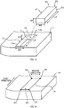
first repair member 20 is embedded into therecess 15, as shown inFig. 5 . Specifically, thesides 21 of thefirst repair member 20 are made to correspond to thelong sides 13a of thecut line 13, thesides 22 of thefirst repair member 20 are made to correspond to theshort sides 13b of thecut line 13 and thesides 23 of thefirst repair member 20 are made to correspond to thesides 14 along the depth direction of therecess 15 to fit thefirst repair member 20 into therecess 15. And then thefirst repair member 20 is pushed into therecess 15 by tapping the surface side thereof. - Here, the material of the
first repair member 20 is made of a metal material that is more flexible with respect to the material (cast steel) of thesurface 11. The reason for this is as follows. Although thesurface 11 where thecrack 12 was generated is a part to which thermal stress is likely to occur, it is unlikely that a crack would generate from the repaired part, because fitting therein thefirst repair member 20 that is more flexible with respect to the cast steel which is the material of thesurface 11 allows the thermal stress on thefirst repair member 20 to be dispersed to the surroundings thereof. - Pure nickel can be given as an example of this material for such
first repair member 20. The purity of the nickel is preferably 99. 9% and greater. Further, for example, chrome, steel, aluminum and the like are suitable for metals besides nickel and the purity thereof in these cases are preferably 99.9999% and greater. - Subsequently, spot welding is performed to the
first repair member 20 as indicated with thereference numbers 24 inFig. 6 . In other words, the corners of thefirst repair member 20 are joined to the parent material at thesurface 11 by spot welding. Spot welding is performed to the four corners in the example ofFig. 6 . This spot welding can be performed by, for example, Tungsten Inert Gas (TIG) welding. - The
first repair member 20 requires to be a metal material to which such spot welding can be performed. And the aforementioned pure nickel and the like satisfy this condition. - Then the part that was repaired using the
first repair member 20 is further reinforced.Fig. 7 illustrates the member (hereinafter, second repair member 30) used for this reinforcement. As shown inFig. 7 , thesecond repair member 30 is a member in a strip form. - The
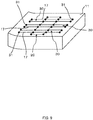
second repair member 30 is mounted on thesurface 11 of the parent material.Fig. 8 is an explanatory view illustrating the manner in which thesecond repair member 30 is mounted to the parent material. As shown inFig. 8 ,grooves 16 are formed to thesurface 11 of the parent material when mounting thesecond repair members 30. - A
groove 16 is formed by cutting thesurface 11 along therectangular cut line 17 that is provided to the surface of the parent material. Thegroove 16 is formed such that thesecond repair member 30 fits therein when thesecond repair member 30 is mounted into thegroove 16. Thegroove 16 is formed using a tool such as, for example, a cutter, an end mill or the like. Thegroove 16 may be formed by removing thesurface 11 by other machine work such as grinding. - As illustrated in
Fig. 8 , thegroove 16 is provided to span over thefirst repair member 20 where the lengthwise direction of thegroove 16 is set in a direction that intersects the lengthwise direction (first direction) of thefirst repair member 20. The lengthwise direction of thegroove 16 comes preferably along the direction (parallel to the crosswise direction of the crack 12) that forms an approximate right angle (80 to 90 degrees) between the lengthwise direction. The angle formed between the lengthwise direction of thegroove 16 and the lengthwise direction is an approximate right angle in also the present embodiment. - The depth of the
groove 16 matches the thickness of thesecond repair member 30 and is preferably designed such that thesecond repair member 30 is mount flush with the parent material surface that is associated with the repair part when thesecond repair member 30 is mounted. The depth of thegroove 16 and the thickness of thesecond repair member 30 match each other in also the present embodiment. - The lengthwise length of the
groove 16 is, for example, 5mm to 100mm, the crosswise (in a direction parallel to the lengthwise direction of the first repair member 20) length of thegroove 16 is, for example, 1mm to 20 mm, and the length along the depth direction of thegroove 16 is, for example 1mm to 20mm. The present embodiment assumes that the length along the lengthwise direction of thegroove 16 is L3, the length along the crosswise direction of thegroove 16 is W3 and that along the depth direction (material thickness direction) of thegroove 16 is D3, as shown inFig. 8 . Therefore, the length along the lengthwise direction of thesecond repair member 30 is L3, the length along the width direction of thesecond repair member 30 is W3 and the length along the thickness direction of thesecond repair member 30 is D3. - Similar to the
first repair member 20, the material of thesecond repair member 30 is a metal material that can have performed spot welding thereto. Additionally, same as thefirst repair member 20, the material of thesecond repair member 30 is preferably a metal material that is more flexible with respect to thesurface 11. The material of thefirst repair member 20 being the same as that of thesecond repair member 30 allows thermal stress on the repair part to be evenly dispersed to the surroundings thereof so that crack generation from the repair part can be effectively suppressed. - The aforementioned pure nickel can be given as an example of this material for such
second repair member 30. The purity of the nickel is preferably at least 99.9% and greater. Further, for example, chrome, steel, aluminum and the like are metals besides nickel that can be used and the purity thereof in these cases are preferably 99.9999% and greater. - Lastly, the
second repair member 30 that is fit into thegroove 16 and the parent material are fixed by spot welding. That is, the four corners of thesecond repair member 30 and the four corners of thecut line 17 are respectively fixed by spot welding, as indicated with thereference numbers 31 inFig. 9 . This spot welding is performed by, for example, Tungsten Inert Gas (TIG) welding. - Hereby, mounting of the
second repair member 30 in the direction intersecting the lengthwise direction of thefirst repair member 20, that is, the direction intersecting the lengthwise direction of thecrack 12 effectively prevents a crack from generating from the repair part. That is, because the direction that intersects the direction (lengthwise direction of the crack 12) in which thecrack 12 was generated is the direction in which thermal stress is likely to occur, cracks can be effectively prevented from generating by making the material of thesecond repair member 30 more flexible with respect to the cast steel member, similar to the case of thefirst repair member 20. - And in this case, on site work can be easily carried out since spot welding is performed for welding the
second repair member 30 to the parent material, similar to the case of thefirst repair member 20. - As described above, in the repair method according to the present embodiment, fitting into the
recess 15 thefirst repair member 20 made of a metal that is more flexible with respect to the cast steel member being the member to be repaired as well as a metal that is weldable to the cast steel member allows thisfirst repair member 20 to release to the surroundings the thermal stress applied to this repair part and therefore cracks can be prevented from generating from the repaired part. Hereby, cracks that were generated to the surface of the cast steel member due to thermal stress can be certainly repaired. - In particular, the cracks that were generated due to thermal stress are likely to appear on the surface of a member. And therefore, forming the
first repair member 20 in a shape that fits into therecess 15 and allowing thefirst repair member 20 embedded in therecess 15 to contact the surface of therecess 15 can effectively prevent cracks from generating from the surface of therecess 15. - Further, in the repair method according to the present embodiment, welding the
first repair member 20 and thesecond repair member 30 to the parent material is performed by spot welding which allows easy site work. Hereby, cracks can be certainly repaired on site even when the cracks were generated to large size cast steel members such as those equipped to thermal power plants, nuclear power plants or the like. - The aforementioned description of the embodiments is simply for facilitating the understanding of the present invention and is not in any way to be construed as limiting the present invention. The present invention may variously be changed or altered without departing from its spirit and encompasses equivalents thereof.
- For example,
Figs. 8 and9 have been illustrated to provide a plurality of thesecond repair members 30, however, only onesecond repair member 30 may be provided when thecrack 12 is short. - 10 turbine wheel chamber shell member, 11 surface, 12 crack, 13 cut line, 13a long side, 13b short side, 14 side in depth direction, 15 recess, 16 groove, 17 cut line, 20 first repair member, 21 side, 22 side, 23 side, 30 second repair member
Claims (5)
- A repair method for repairing a crack generated to a cast steel member due to a thermal stress, comprising:removing a part including the crack at a surface of the cast steel member and forming a recess;fitting into the recess a first repair member that is made of a metal that is more flexible with respect to the cast steel member and that is weldable to the cast steel member; andjoining by spot welding to the cast steel member the first repair member that was fit in.
- A method of repairing a cast steel member according to claim 1, wherein
a strip-form second repair member that is made of a metal that is more flexible with respect to the cast steel member and that is weldable to the cast steel member is welded in a manner intersecting a lengthwise direction of the crack and spanning over the first repair member that was fit in. - A method of repairing a cast steel member according to claim 2, wherein
the mounted second repair member and a main body of the cast steel member are joined by spot welding. - A method of repairing a cast steel member according to claim 2 or 3, wherein
the first repair member and the second repair member are made of a same material. - A method of repairing a cast steel member according to claim 4, wherein
the first repair member and the second repair member are metal members made of nickel that has a purity of 99.9% and greater.
Priority Applications (1)
| Application Number | Priority Date | Filing Date | Title |
|---|---|---|---|
| PL14882560T PL3106257T3 (en) | 2014-02-13 | 2014-02-13 | Method for repairing cast steel member |
Applications Claiming Priority (1)
| Application Number | Priority Date | Filing Date | Title |
|---|---|---|---|
| PCT/JP2014/053272 WO2015121936A1 (en) | 2014-02-13 | 2014-02-13 | Method for repairing cast steel member |
Publications (3)
| Publication Number | Publication Date |
|---|---|
| EP3106257A1 true EP3106257A1 (en) | 2016-12-21 |
| EP3106257A4 EP3106257A4 (en) | 2017-03-01 |
| EP3106257B1 EP3106257B1 (en) | 2018-04-11 |
Family
ID=53799705
Family Applications (1)
| Application Number | Title | Priority Date | Filing Date |
|---|---|---|---|
| EP14882560.7A Active EP3106257B1 (en) | 2014-02-13 | 2014-02-13 | Method for repairing cast steel member |
Country Status (9)
| Country | Link |
|---|---|
| US (1) | US9962797B2 (en) |
| EP (1) | EP3106257B1 (en) |
| JP (1) | JP5996789B2 (en) |
| KR (1) | KR20160105502A (en) |
| CN (1) | CN105980101A (en) |
| CA (1) | CA2939466C (en) |
| PH (1) | PH12016501599A1 (en) |
| PL (1) | PL3106257T3 (en) |
| WO (1) | WO2015121936A1 (en) |
Families Citing this family (11)
| Publication number | Priority date | Publication date | Assignee | Title |
|---|---|---|---|---|
| WO2016139772A1 (en) * | 2015-03-04 | 2016-09-09 | 中国電力株式会社 | Method for repairing cast steel member |
| CN105149727B (en) * | 2015-09-24 | 2017-11-28 | 共享铸钢有限公司 | A kind of medium carbon steel casting defect minimizing technology |
| EP3208029B1 (en) * | 2016-02-17 | 2021-01-27 | General Electric Technology GmbH | Steam turbine inner casing component and repair method therefor |
| DE102016204660A1 (en) * | 2016-03-22 | 2017-09-28 | MTU Aero Engines AG | Method for producing a housing of a turbomachine and housing of a turbomachine |
| US20180126499A1 (en) * | 2016-11-08 | 2018-05-10 | General Electric Company | Threaded coupon for repair of superalloy part |
| CN106583881A (en) * | 2016-12-13 | 2017-04-26 | 西安铂力特激光成形技术有限公司 | Cast iron arc welding repair method |
| US20180250762A1 (en) * | 2017-03-06 | 2018-09-06 | General Electric Company | Narrow gap processing |
| CN109722632A (en) * | 2017-10-31 | 2019-05-07 | 陕西南水汽车配件制造有限公司 | A kind of aluminum alloy control arm forging coarse grains on surface ring control method |
| CN112846639B (en) * | 2020-12-25 | 2024-08-16 | 华电江苏能源有限公司句容发电分公司 | Method for repairing broken millstone steel tile lining plate of medium-speed coal mill |
| CN113500270B (en) * | 2021-06-30 | 2023-03-07 | 共享铸钢有限公司 | Welding method for surface defects of steel castings |
| CN117226228B (en) * | 2023-10-21 | 2025-10-28 | 郑州国电机械设计研究所有限公司 | Welding repair and reinforcement technology for cracks in the main frame of wind turbines |
Family Cites Families (27)
| Publication number | Priority date | Publication date | Assignee | Title |
|---|---|---|---|---|
| US1340644A (en) * | 1918-09-14 | 1920-05-18 | David H Wilson | Reinforced welded joint |
| CA969732A (en) * | 1972-05-24 | 1975-06-24 | Egon Evertz | Method for repairing cast iron objects including casting moulds |
| GB1379113A (en) * | 1973-06-11 | 1975-01-02 | Foseco Int | Repairing ingot moulds |
| US4068111A (en) * | 1975-08-20 | 1978-01-10 | De Rotterdamsche Droogdok Maatschappij B.V. | Process of working imperfections or defects on generally thickwalled metal worked-pieces |
| SU1303352A1 (en) * | 1981-11-25 | 1987-04-15 | Государственный Всесоюзный Научно-Исследовательский Технологический Институт Ремонта И Эксплуатации Машинно-Тракторного Парка | Method of repairing cracked cast-iron parts |
| US4662806A (en) * | 1983-11-17 | 1987-05-05 | Reed International, Incorporated | Metal lock system and method |
| US4599781A (en) * | 1984-12-17 | 1986-07-15 | David Diperstein | Method of repairing cracked thin metal parts |
| GB2198667B (en) * | 1986-12-20 | 1991-08-07 | Refurbished Turbine Components | Parts for and methods of repairing machines |
| US4845828A (en) * | 1987-04-15 | 1989-07-11 | Reed Gary J | Method for repairing a metal casting having a crack or break therein |
| GB2227190B (en) * | 1989-01-24 | 1992-12-16 | Refurbished Turbine Components | Turbine blade repair |
| GB8904988D0 (en) * | 1989-03-04 | 1989-04-19 | Refurbished Turbine Components | Turbine blade repair |
| US5085363A (en) * | 1990-11-01 | 1992-02-04 | Westinghouse Electric Corp. | Method of weld repairing of a section of a metallic cylindrical member |
| GB9210191D0 (en) * | 1992-05-12 | 1992-06-24 | Turbine Blading Ltd | Turbine blade repair |
| US5494539A (en) * | 1993-08-30 | 1996-02-27 | Hitachi, Ltd. | Metal member quality improving method by spot welding |
| JP3079902B2 (en) * | 1994-07-05 | 2000-08-21 | 株式会社日立製作所 | Welding repair method for reactor internals |
| CN1042901C (en) * | 1995-03-18 | 1999-04-14 | 王富山 | Technology for repairing damaged part with metal fastening |
| EP0734807B1 (en) * | 1995-03-28 | 1997-11-26 | Siempelkamp Guss- und Anlagentechnik Holding GmbH & Co. | Method, apparatus to suppress the defects of the cast iron surface elements |
| US6238187B1 (en) * | 1999-10-14 | 2001-05-29 | Lsp Technologies, Inc. | Method using laser shock peening to process airfoil weld repairs pertaining to blade cut and weld techniques |
| DE10008257A1 (en) | 2000-02-23 | 2001-08-30 | Alstom Power Schweiz Ag Baden | Process for repairing a gas turbine component |
| US6413041B1 (en) * | 2000-08-02 | 2002-07-02 | Siemens Westinghouse Power Corporation | Method and apparatus for closing holes in superalloy gas turbine blades |
| DE102006017663A1 (en) * | 2006-04-12 | 2007-10-18 | Linde Ag | Method for repair welding of casting material and use thereof in a protective gas mixture |
| EP1857218A1 (en) * | 2006-05-18 | 2007-11-21 | Siemens Aktiengesellschaft | Method for repairing a component and a component |
| US20090250447A1 (en) * | 2008-04-02 | 2009-10-08 | Bela Guth | Capilary electrical welding process for the repair of carbon steel, of high, medium and low alloy, in the condition of tempered or not; hadfield steel; cast iron; nickel and its alloys; metallic covering and dissimilar bonds, to produce an appropriate microstructure in the welded bond without the need of post-welding thermal treatment |
| GB0816255D0 (en) * | 2008-09-08 | 2008-10-15 | Rolls Royce Plc | A method of repairing an aluminide coating on an article |
| JP2011214541A (en) | 2010-04-01 | 2011-10-27 | Toshiba Ge Turbine Service Kk | Method of repairing turbine blade and repaired turbine blade |
| CN202045477U (en) * | 2010-12-31 | 2011-11-23 | 重庆市银盛模具有限公司 | Mould mending block |
| CN104039482B (en) * | 2011-12-15 | 2016-01-20 | 维斯塔斯风力系统集团公司 | Repair the method for defect in cast iron part and the method being connected cast iron part |
-
2014
- 2014-02-13 US US15/118,499 patent/US9962797B2/en active Active
- 2014-02-13 WO PCT/JP2014/053272 patent/WO2015121936A1/en not_active Ceased
- 2014-02-13 CN CN201480075520.7A patent/CN105980101A/en active Pending
- 2014-02-13 JP JP2015512422A patent/JP5996789B2/en not_active Expired - Fee Related
- 2014-02-13 KR KR1020167021060A patent/KR20160105502A/en not_active Ceased
- 2014-02-13 CA CA2939466A patent/CA2939466C/en active Active
- 2014-02-13 PL PL14882560T patent/PL3106257T3/en unknown
- 2014-02-13 EP EP14882560.7A patent/EP3106257B1/en active Active
-
2016
- 2016-08-11 PH PH12016501599A patent/PH12016501599A1/en unknown
Also Published As
| Publication number | Publication date |
|---|---|
| JPWO2015121936A1 (en) | 2017-03-30 |
| JP5996789B2 (en) | 2016-09-21 |
| US9962797B2 (en) | 2018-05-08 |
| US20170182606A1 (en) | 2017-06-29 |
| PL3106257T3 (en) | 2018-09-28 |
| CA2939466A1 (en) | 2015-08-20 |
| EP3106257B1 (en) | 2018-04-11 |
| KR20160105502A (en) | 2016-09-06 |
| WO2015121936A1 (en) | 2015-08-20 |
| CN105980101A (en) | 2016-09-28 |
| EP3106257A4 (en) | 2017-03-01 |
| CA2939466C (en) | 2018-08-14 |
| PH12016501599A1 (en) | 2017-02-06 |
Similar Documents
| Publication | Publication Date | Title |
|---|---|---|
| EP3106257B1 (en) | Method for repairing cast steel member | |
| CA2845590C (en) | Localized cleaning process and apparatus therefor | |
| EP1892374B2 (en) | Method of repairing shrouded turbine blades with cracks in the vicinity of the outer shroud notch | |
| US9199342B2 (en) | Repairing method for wall member with flow passages | |
| JP6581498B2 (en) | Turbine rotor disk repair method | |
| EP2764949B1 (en) | Material removal method | |
| JP2012020308A (en) | Method for repairing metal component and the repaired metal component | |
| CN110449737A (en) | A method of repairing housing of power cell and the fried point of top cover Laser Welding | |
| JP2015531039A (en) | Stud welding repair of superalloy parts | |
| CN101219545A (en) | Method and apparatus for removing pins in confined spaces | |
| US20070068648A1 (en) | Method for repairing die cast dies | |
| JP6217891B1 (en) | Repair method for cast steel members | |
| EP3586076B1 (en) | Cooling panel for metallurgical furnace | |
| CN105328395A (en) | Method for eliminating cracks of high-strength steel casting | |
| JP5599492B1 (en) | Stud bolt connection member and method for repairing the inner surface of an industrial furnace | |
| KR101157790B1 (en) | Plasma processing equipment | |
| US20180009069A1 (en) | Repair method of cast steel member | |
| KR101482409B1 (en) | Continuouse strip welding apparatus | |
| JP2012245555A (en) | Industrial roll and method for manufacturing the same | |
| JP2007206026A (en) | Repairing method for structure in inside of nuclear pressure vessel | |
| CN120170158A (en) | Method and apparatus for repairing the cutting edge of a hacksaw blade | |
| WO2004065051A1 (en) | Turbine refurbishment | |
| Dabin et al. | A NEW GENERATION OF X RAY ABSORBERS FOR A NEW GENERATION OF X-RAY ABSORBERS FOR THE ESRF EBS STORAGE RING | |
| Yanyan et al. | Quality Certification for Automotive Body's Ar Plas Welding | |
| WO2018131107A1 (en) | Method for repairing cast steel member |
Legal Events
| Date | Code | Title | Description |
|---|---|---|---|
| PUAI | Public reference made under article 153(3) epc to a published international application that has entered the european phase |
Free format text: ORIGINAL CODE: 0009012 |
|
| STAA | Information on the status of an ep patent application or granted ep patent |
Free format text: STATUS: REQUEST FOR EXAMINATION WAS MADE |
|
| 17P | Request for examination filed |
Effective date: 20160902 |
|
| AK | Designated contracting states |
Kind code of ref document: A1 Designated state(s): AL AT BE BG CH CY CZ DE DK EE ES FI FR GB GR HR HU IE IS IT LI LT LU LV MC MK MT NL NO PL PT RO RS SE SI SK SM TR |
|
| AX | Request for extension of the european patent |
Extension state: BA ME |
|
| A4 | Supplementary search report drawn up and despatched |
Effective date: 20170130 |
|
| RIC1 | Information provided on ipc code assigned before grant |
Ipc: B23K 31/00 20060101AFI20170124BHEP Ipc: B23K 103/06 20060101ALI20170124BHEP Ipc: B23K 9/167 20060101ALI20170124BHEP Ipc: B23K 9/007 20060101ALI20170124BHEP Ipc: B23K 9/00 20060101ALI20170124BHEP Ipc: B23P 6/04 20060101ALI20170124BHEP Ipc: F01D 5/00 20060101ALI20170124BHEP |
|
| DAX | Request for extension of the european patent (deleted) | ||
| RIC1 | Information provided on ipc code assigned before grant |
Ipc: B23K 103/06 20060101ALI20170904BHEP Ipc: B23P 6/04 20060101ALI20170904BHEP Ipc: F01D 5/00 20060101ALI20170904BHEP Ipc: B23K 9/007 20060101ALI20170904BHEP Ipc: B23K 9/167 20060101ALI20170904BHEP Ipc: B23K 101/00 20060101ALI20170904BHEP Ipc: B23K 31/00 20060101AFI20170904BHEP Ipc: B23K 9/00 20060101ALI20170904BHEP Ipc: F01D 25/24 20060101ALI20170904BHEP |
|
| GRAP | Despatch of communication of intention to grant a patent |
Free format text: ORIGINAL CODE: EPIDOSNIGR1 |
|
| STAA | Information on the status of an ep patent application or granted ep patent |
Free format text: STATUS: GRANT OF PATENT IS INTENDED |
|
| INTG | Intention to grant announced |
Effective date: 20171018 |
|
| GRAS | Grant fee paid |
Free format text: ORIGINAL CODE: EPIDOSNIGR3 |
|
| GRAA | (expected) grant |
Free format text: ORIGINAL CODE: 0009210 |
|
| STAA | Information on the status of an ep patent application or granted ep patent |
Free format text: STATUS: THE PATENT HAS BEEN GRANTED |
|
| AK | Designated contracting states |
Kind code of ref document: B1 Designated state(s): AL AT BE BG CH CY CZ DE DK EE ES FI FR GB GR HR HU IE IS IT LI LT LU LV MC MK MT NL NO PL PT RO RS SE SI SK SM TR |
|
| REG | Reference to a national code |
Ref country code: GB Ref legal event code: FG4D |
|
| REG | Reference to a national code |
Ref country code: CH Ref legal event code: EP |
|
| REG | Reference to a national code |
Ref country code: AT Ref legal event code: REF Ref document number: 987478 Country of ref document: AT Kind code of ref document: T Effective date: 20180415 |
|
| REG | Reference to a national code |
Ref country code: IE Ref legal event code: FG4D |
|
| REG | Reference to a national code |
Ref country code: DE Ref legal event code: R096 Ref document number: 602014023952 Country of ref document: DE |
|
| REG | Reference to a national code |
Ref country code: NL Ref legal event code: MP Effective date: 20180411 |
|
| REG | Reference to a national code |
Ref country code: LT Ref legal event code: MG4D |
|
| PG25 | Lapsed in a contracting state [announced via postgrant information from national office to epo] |
Ref country code: NL Free format text: LAPSE BECAUSE OF FAILURE TO SUBMIT A TRANSLATION OF THE DESCRIPTION OR TO PAY THE FEE WITHIN THE PRESCRIBED TIME-LIMIT Effective date: 20180411 |
|
| PG25 | Lapsed in a contracting state [announced via postgrant information from national office to epo] |
Ref country code: PT Free format text: LAPSE BECAUSE OF FAILURE TO SUBMIT A TRANSLATION OF THE DESCRIPTION OR TO PAY THE FEE WITHIN THE PRESCRIBED TIME-LIMIT Effective date: 20180813 Ref country code: NO Free format text: LAPSE BECAUSE OF FAILURE TO SUBMIT A TRANSLATION OF THE DESCRIPTION OR TO PAY THE FEE WITHIN THE PRESCRIBED TIME-LIMIT Effective date: 20180711 Ref country code: SE Free format text: LAPSE BECAUSE OF FAILURE TO SUBMIT A TRANSLATION OF THE DESCRIPTION OR TO PAY THE FEE WITHIN THE PRESCRIBED TIME-LIMIT Effective date: 20180411 Ref country code: FI Free format text: LAPSE BECAUSE OF FAILURE TO SUBMIT A TRANSLATION OF THE DESCRIPTION OR TO PAY THE FEE WITHIN THE PRESCRIBED TIME-LIMIT Effective date: 20180411 Ref country code: BG Free format text: LAPSE BECAUSE OF FAILURE TO SUBMIT A TRANSLATION OF THE DESCRIPTION OR TO PAY THE FEE WITHIN THE PRESCRIBED TIME-LIMIT Effective date: 20180711 Ref country code: AL Free format text: LAPSE BECAUSE OF FAILURE TO SUBMIT A TRANSLATION OF THE DESCRIPTION OR TO PAY THE FEE WITHIN THE PRESCRIBED TIME-LIMIT Effective date: 20180411 Ref country code: ES Free format text: LAPSE BECAUSE OF FAILURE TO SUBMIT A TRANSLATION OF THE DESCRIPTION OR TO PAY THE FEE WITHIN THE PRESCRIBED TIME-LIMIT Effective date: 20180411 Ref country code: LT Free format text: LAPSE BECAUSE OF FAILURE TO SUBMIT A TRANSLATION OF THE DESCRIPTION OR TO PAY THE FEE WITHIN THE PRESCRIBED TIME-LIMIT Effective date: 20180411 |
|
| PG25 | Lapsed in a contracting state [announced via postgrant information from national office to epo] |
Ref country code: LV Free format text: LAPSE BECAUSE OF FAILURE TO SUBMIT A TRANSLATION OF THE DESCRIPTION OR TO PAY THE FEE WITHIN THE PRESCRIBED TIME-LIMIT Effective date: 20180411 Ref country code: HR Free format text: LAPSE BECAUSE OF FAILURE TO SUBMIT A TRANSLATION OF THE DESCRIPTION OR TO PAY THE FEE WITHIN THE PRESCRIBED TIME-LIMIT Effective date: 20180411 Ref country code: GR Free format text: LAPSE BECAUSE OF FAILURE TO SUBMIT A TRANSLATION OF THE DESCRIPTION OR TO PAY THE FEE WITHIN THE PRESCRIBED TIME-LIMIT Effective date: 20180712 Ref country code: RS Free format text: LAPSE BECAUSE OF FAILURE TO SUBMIT A TRANSLATION OF THE DESCRIPTION OR TO PAY THE FEE WITHIN THE PRESCRIBED TIME-LIMIT Effective date: 20180411 |
|
| REG | Reference to a national code |
Ref country code: AT Ref legal event code: MK05 Ref document number: 987478 Country of ref document: AT Kind code of ref document: T Effective date: 20180411 |
|
| REG | Reference to a national code |
Ref country code: DE Ref legal event code: R097 Ref document number: 602014023952 Country of ref document: DE |
|
| PG25 | Lapsed in a contracting state [announced via postgrant information from national office to epo] |
Ref country code: AT Free format text: LAPSE BECAUSE OF FAILURE TO SUBMIT A TRANSLATION OF THE DESCRIPTION OR TO PAY THE FEE WITHIN THE PRESCRIBED TIME-LIMIT Effective date: 20180411 Ref country code: DK Free format text: LAPSE BECAUSE OF FAILURE TO SUBMIT A TRANSLATION OF THE DESCRIPTION OR TO PAY THE FEE WITHIN THE PRESCRIBED TIME-LIMIT Effective date: 20180411 Ref country code: EE Free format text: LAPSE BECAUSE OF FAILURE TO SUBMIT A TRANSLATION OF THE DESCRIPTION OR TO PAY THE FEE WITHIN THE PRESCRIBED TIME-LIMIT Effective date: 20180411 Ref country code: CZ Free format text: LAPSE BECAUSE OF FAILURE TO SUBMIT A TRANSLATION OF THE DESCRIPTION OR TO PAY THE FEE WITHIN THE PRESCRIBED TIME-LIMIT Effective date: 20180411 Ref country code: RO Free format text: LAPSE BECAUSE OF FAILURE TO SUBMIT A TRANSLATION OF THE DESCRIPTION OR TO PAY THE FEE WITHIN THE PRESCRIBED TIME-LIMIT Effective date: 20180411 Ref country code: SK Free format text: LAPSE BECAUSE OF FAILURE TO SUBMIT A TRANSLATION OF THE DESCRIPTION OR TO PAY THE FEE WITHIN THE PRESCRIBED TIME-LIMIT Effective date: 20180411 |
|
| PLBE | No opposition filed within time limit |
Free format text: ORIGINAL CODE: 0009261 |
|
| STAA | Information on the status of an ep patent application or granted ep patent |
Free format text: STATUS: NO OPPOSITION FILED WITHIN TIME LIMIT |
|
| PG25 | Lapsed in a contracting state [announced via postgrant information from national office to epo] |
Ref country code: SM Free format text: LAPSE BECAUSE OF FAILURE TO SUBMIT A TRANSLATION OF THE DESCRIPTION OR TO PAY THE FEE WITHIN THE PRESCRIBED TIME-LIMIT Effective date: 20180411 |
|
| REG | Reference to a national code |
Ref country code: DE Ref legal event code: R082 Ref document number: 602014023952 Country of ref document: DE Representative=s name: DOMPATENT VON KREISLER SELTING WERNER - PARTNE, DE |
|
| 26N | No opposition filed |
Effective date: 20190114 |
|
| PG25 | Lapsed in a contracting state [announced via postgrant information from national office to epo] |
Ref country code: SI Free format text: LAPSE BECAUSE OF FAILURE TO SUBMIT A TRANSLATION OF THE DESCRIPTION OR TO PAY THE FEE WITHIN THE PRESCRIBED TIME-LIMIT Effective date: 20180411 |
|
| REG | Reference to a national code |
Ref country code: CH Ref legal event code: PL |
|
| PG25 | Lapsed in a contracting state [announced via postgrant information from national office to epo] |
Ref country code: MC Free format text: LAPSE BECAUSE OF FAILURE TO SUBMIT A TRANSLATION OF THE DESCRIPTION OR TO PAY THE FEE WITHIN THE PRESCRIBED TIME-LIMIT Effective date: 20180411 Ref country code: LU Free format text: LAPSE BECAUSE OF NON-PAYMENT OF DUE FEES Effective date: 20190213 |
|
| REG | Reference to a national code |
Ref country code: BE Ref legal event code: MM Effective date: 20190228 |
|
| REG | Reference to a national code |
Ref country code: IE Ref legal event code: MM4A |
|
| PG25 | Lapsed in a contracting state [announced via postgrant information from national office to epo] |
Ref country code: LI Free format text: LAPSE BECAUSE OF NON-PAYMENT OF DUE FEES Effective date: 20190228 Ref country code: CH Free format text: LAPSE BECAUSE OF NON-PAYMENT OF DUE FEES Effective date: 20190228 |
|
| PG25 | Lapsed in a contracting state [announced via postgrant information from national office to epo] |
Ref country code: IE Free format text: LAPSE BECAUSE OF NON-PAYMENT OF DUE FEES Effective date: 20190213 |
|
| PG25 | Lapsed in a contracting state [announced via postgrant information from national office to epo] |
Ref country code: BE Free format text: LAPSE BECAUSE OF NON-PAYMENT OF DUE FEES Effective date: 20190228 Ref country code: IT Free format text: LAPSE BECAUSE OF NON-PAYMENT OF DUE FEES Effective date: 20190213 |
|
| PG25 | Lapsed in a contracting state [announced via postgrant information from national office to epo] |
Ref country code: TR Free format text: LAPSE BECAUSE OF FAILURE TO SUBMIT A TRANSLATION OF THE DESCRIPTION OR TO PAY THE FEE WITHIN THE PRESCRIBED TIME-LIMIT Effective date: 20180411 |
|
| PG25 | Lapsed in a contracting state [announced via postgrant information from national office to epo] |
Ref country code: MT Free format text: LAPSE BECAUSE OF NON-PAYMENT OF DUE FEES Effective date: 20190213 |
|
| PG25 | Lapsed in a contracting state [announced via postgrant information from national office to epo] |
Ref country code: CY Free format text: LAPSE BECAUSE OF FAILURE TO SUBMIT A TRANSLATION OF THE DESCRIPTION OR TO PAY THE FEE WITHIN THE PRESCRIBED TIME-LIMIT Effective date: 20180411 |
|
| PG25 | Lapsed in a contracting state [announced via postgrant information from national office to epo] |
Ref country code: IS Free format text: LAPSE BECAUSE OF FAILURE TO SUBMIT A TRANSLATION OF THE DESCRIPTION OR TO PAY THE FEE WITHIN THE PRESCRIBED TIME-LIMIT Effective date: 20180811 |
|
| PG25 | Lapsed in a contracting state [announced via postgrant information from national office to epo] |
Ref country code: HU Free format text: LAPSE BECAUSE OF FAILURE TO SUBMIT A TRANSLATION OF THE DESCRIPTION OR TO PAY THE FEE WITHIN THE PRESCRIBED TIME-LIMIT; INVALID AB INITIO Effective date: 20140213 |
|
| PG25 | Lapsed in a contracting state [announced via postgrant information from national office to epo] |
Ref country code: MK Free format text: LAPSE BECAUSE OF FAILURE TO SUBMIT A TRANSLATION OF THE DESCRIPTION OR TO PAY THE FEE WITHIN THE PRESCRIBED TIME-LIMIT Effective date: 20180411 |
|
| PGFP | Annual fee paid to national office [announced via postgrant information from national office to epo] |
Ref country code: PL Payment date: 20241231 Year of fee payment: 12 |
|
| PGFP | Annual fee paid to national office [announced via postgrant information from national office to epo] |
Ref country code: GB Payment date: 20241227 Year of fee payment: 12 |
|
| PGFP | Annual fee paid to national office [announced via postgrant information from national office to epo] |
Ref country code: FR Payment date: 20241231 Year of fee payment: 12 |
|
| PGFP | Annual fee paid to national office [announced via postgrant information from national office to epo] |
Ref country code: DE Payment date: 20241231 Year of fee payment: 12 |