EP3105424B1 - Système d'échangeur de chaleur - Google Patents
Système d'échangeur de chaleur Download PDFInfo
- Publication number
- EP3105424B1 EP3105424B1 EP15706907.1A EP15706907A EP3105424B1 EP 3105424 B1 EP3105424 B1 EP 3105424B1 EP 15706907 A EP15706907 A EP 15706907A EP 3105424 B1 EP3105424 B1 EP 3105424B1
- Authority
- EP
- European Patent Office
- Prior art keywords
- heat exchange
- exchange system
- turbomachine
- work structure
- open work
- Prior art date
- Legal status (The legal status is an assumption and is not a legal conclusion. Google has not performed a legal analysis and makes no representation as to the accuracy of the status listed.)
- Active
Links
Images

Classifications
-
- F—MECHANICAL ENGINEERING; LIGHTING; HEATING; WEAPONS; BLASTING
- F02—COMBUSTION ENGINES; HOT-GAS OR COMBUSTION-PRODUCT ENGINE PLANTS
- F02C—GAS-TURBINE PLANTS; AIR INTAKES FOR JET-PROPULSION PLANTS; CONTROLLING FUEL SUPPLY IN AIR-BREATHING JET-PROPULSION PLANTS
- F02C7/00—Features, components parts, details or accessories, not provided for in, or of interest apart form groups F02C1/00 - F02C6/00; Air intakes for jet-propulsion plants
- F02C7/12—Cooling of plants
- F02C7/16—Cooling of plants characterised by cooling medium
- F02C7/18—Cooling of plants characterised by cooling medium the medium being gaseous, e.g. air
- F02C7/185—Cooling means for reducing the temperature of the cooling air or gas
-
- F—MECHANICAL ENGINEERING; LIGHTING; HEATING; WEAPONS; BLASTING
- F02—COMBUSTION ENGINES; HOT-GAS OR COMBUSTION-PRODUCT ENGINE PLANTS
- F02C—GAS-TURBINE PLANTS; AIR INTAKES FOR JET-PROPULSION PLANTS; CONTROLLING FUEL SUPPLY IN AIR-BREATHING JET-PROPULSION PLANTS
- F02C7/00—Features, components parts, details or accessories, not provided for in, or of interest apart form groups F02C1/00 - F02C6/00; Air intakes for jet-propulsion plants
- F02C7/04—Air intakes for gas-turbine plants or jet-propulsion plants
-
- F—MECHANICAL ENGINEERING; LIGHTING; HEATING; WEAPONS; BLASTING
- F02—COMBUSTION ENGINES; HOT-GAS OR COMBUSTION-PRODUCT ENGINE PLANTS
- F02C—GAS-TURBINE PLANTS; AIR INTAKES FOR JET-PROPULSION PLANTS; CONTROLLING FUEL SUPPLY IN AIR-BREATHING JET-PROPULSION PLANTS
- F02C7/00—Features, components parts, details or accessories, not provided for in, or of interest apart form groups F02C1/00 - F02C6/00; Air intakes for jet-propulsion plants
- F02C7/04—Air intakes for gas-turbine plants or jet-propulsion plants
- F02C7/047—Heating to prevent icing
-
- F—MECHANICAL ENGINEERING; LIGHTING; HEATING; WEAPONS; BLASTING
- F02—COMBUSTION ENGINES; HOT-GAS OR COMBUSTION-PRODUCT ENGINE PLANTS
- F02C—GAS-TURBINE PLANTS; AIR INTAKES FOR JET-PROPULSION PLANTS; CONTROLLING FUEL SUPPLY IN AIR-BREATHING JET-PROPULSION PLANTS
- F02C7/00—Features, components parts, details or accessories, not provided for in, or of interest apart form groups F02C1/00 - F02C6/00; Air intakes for jet-propulsion plants
- F02C7/04—Air intakes for gas-turbine plants or jet-propulsion plants
- F02C7/05—Air intakes for gas-turbine plants or jet-propulsion plants having provisions for obviating the penetration of damaging objects or particles
- F02C7/055—Air intakes for gas-turbine plants or jet-propulsion plants having provisions for obviating the penetration of damaging objects or particles with intake grids, screens or guards
-
- Y—GENERAL TAGGING OF NEW TECHNOLOGICAL DEVELOPMENTS; GENERAL TAGGING OF CROSS-SECTIONAL TECHNOLOGIES SPANNING OVER SEVERAL SECTIONS OF THE IPC; TECHNICAL SUBJECTS COVERED BY FORMER USPC CROSS-REFERENCE ART COLLECTIONS [XRACs] AND DIGESTS
- Y02—TECHNOLOGIES OR APPLICATIONS FOR MITIGATION OR ADAPTATION AGAINST CLIMATE CHANGE
- Y02T—CLIMATE CHANGE MITIGATION TECHNOLOGIES RELATED TO TRANSPORTATION
- Y02T50/00—Aeronautics or air transport
- Y02T50/60—Efficient propulsion technologies, e.g. for aircraft
Definitions
- the invention proposes a heat exchanger system for an aircraft turbine engine comprising a radial air inlet.
- the invention more particularly proposes a heat exchanger system for cooling a fluid for lubricating and/or cooling equipment of the turbomachine, in which the cold source of the heat exchanger is constituted by the flow of air at the entrance to the turbomachine.
- An aircraft turbomachine comprises a plurality of members and equipment which must be lubricated and/or cooled constantly during the operation of the turbomachine.
- the turbomachine To limit the temperature of this fluid, it is known to equip the turbomachine with one or more heat exchange devices, which are configured to exchange heat between the fluid and a cold source which is formed by the outside air. circulating close to the outer casing of the turbomachine or else which is formed by an external air flow dedicated to this function.
- the object of the invention is to propose a heat exchanger system integrated into the general structure of the turbomachine, which also acts as an anti-icing system for the air inlet of the turbomachine.
- the invention proposes a heat exchange system in a turbomachine comprising a plurality of members and equipment to be cooled and/or lubricated, said system comprising a fluidic circuit for cooling and / or lubricate said equipment, said heat exchange system being configured to put said fluidic circuit in thermal contact with a fluid acting as a cold source on the other hand, characterized in that the heat exchange system comprises a perforated structure which is in thermal contact with at least one hot section of the fluidic circuit and which is traversed radially by an intake air flow from the turbomachine forming the cold source .
- This perforated structure used to carry out the heat transfer between the hot fluid and the intake air flow which constitutes the cold source makes it possible to use the heat taken from the hot fluid to heat the solid structure, in order to avoid any accretion of water or ice crystals on this structure, which could have been brought in by the air flow admitted during operation of the turbomachine in icing conditions.
- a heat exchange system 10 for a turbine engine configured with a radial air inlet, for example an aircraft turbine engine.
- the turbomachine comprises a plurality of components and members which heat up during the operation of the turbomachine, and which need to be cooled or to be lubricated continuously.
- the turbomachine comprises a main fluidic circuit which supplies all the components and organs of the turbomachine with a fluid which is capable of lubricating or cooling them.
- the main fluidic circuit is associated with the heat exchange system 10 represented in the figures, which makes it possible to cool the fluid which has circulated through these components and bodies.
- the heat exchange system 10 comprises a fluidic circuit 12 which is connected to the main fluidic circuit or else which constitutes the latter and it is configured so that a heat exchange can take place between the hot fluid and a cold source 14 .
- the heat exchange system 10 is configured to put the fluidic circuit 12 in thermal contact with the cold source 14.
- the cold source 14 consists of an air flow, for example the air flow which is admitted into the turbomachine.
- This air flow is at a temperature close to the ambient outside temperature, which can be very low, especially when the aircraft is flying at high altitude.
- the heat exchange system 10 comprises an openwork structure 16 comprising a plurality of openings 15 through which the flow of air 14 and which is in thermal contact with the fluid of the fluidic circuit.
- the perforated structure 16 of the heat exchange system 10 is heated by the hot fluid, which prevents the accretion, or the accumulation of ice crystals thereon, at the level of the inlet of air from the turbomachine, when the aircraft is flying in icing external conditions.
- the heat exchange between the hot fluid circulating in the fluidic circuit 12 and the flow of air passing through the perforated structure 16 makes it possible both to cool the fluid and to heat the perforated structure 16 to limit the accretion of ice crystals.
- the perforated structure 16 is designed so that the hot fluid can pass through it.
- the perforated structure 16 consists of a hollow element, for example produced by assembling two plates which are themselves perforated, through which the hot fluid passes.
- the perforated structure 16 is of cylindrical shape of revolution, and it is connected to the fluidic circuit 12 at its two axial ends.
- the air flow passes through the perforated structure 16 radially, with respect to its main axis A.
- the perforated structure 16 consists of an assembly of two coaxial cylindrical perforated plates in which there are openings 15, the shape of which is, for example, circular or rectangular.
- the perforated structure 16 may consist of a double-skin system, the inner skin of which is in contact with the hot fluid and the outer skin in contact with the flow of air 14 admitted.
- a first axial end 16a of the perforated structure is open and forms an inlet for the hot fluid
- the second axial end 16b of the perforated structure 16 is also open and forms an outlet for the cooled fluid.
- the perforated structure 16 forms a grid which is made in part from sections 18 of the fluidic circuit 12.
- the perforated structure 16 is of cylindrical shape of revolution.
- the sections 18 of the fluidic circuit 12 are all parallel to the main axis A of the perforated structure 16 and they are distributed regularly or not around the main axis A of the perforated structure 16.
- the sections 18 of the fluidic circuit 12 constitute structural elements of the perforated structure 16, so that the heat transfer takes place by heat conduction with the other components of the perforated structure 16 and by heat exchange directly with the flow of heat. air 14.
- the perforated structure 16 consists of a grid and a section 20 of the fluidic circuit 12 forms a structural element of the perforated structure 16.
- This section 20 of the fluidic circuit 12 is in the form of a helical winding coaxial with the main axis A of the perforated structure 16.
- the perforated structure 16 comprises several sections 20 in the form of a helical winding.
- the heat exchange system 10 may comprise a perforated structure 16 in the form of a grid formed from sections 18 parallel to the main axis of the perforated structure 16 and from at least one section 20 of helical.
- the perforated structure 16 may consist of a double-skin structure whose outer skin is in contact with the air flow 14 and which comprises internal tubes formed from sections 18, 20 of the fluidic circuit 12. The transfer of heat between the external skin and the internal tubes taking place for example by thermal bridges.
- the perforated structure 16 is in the form of a flat ring, that is to say having an axial air inlet.
- the section(s) of the fluidic circuit 12 constituting the perforated structure 16 are either rectilinear sections oriented radially with respect to the main axis of the perforated structure 16, or else one or more sections in the form of spiral centered on the main axis of the openwork structure 16.
- the perforated structure 16 in the form of a flat ring consists of a hollow element, it is made by assembling two parallel flat perforated plates and is open at each of its internal and external radial ends.
Landscapes
- Engineering & Computer Science (AREA)
- Chemical & Material Sciences (AREA)
- Combustion & Propulsion (AREA)
- Mechanical Engineering (AREA)
- General Engineering & Computer Science (AREA)
- Heat-Exchange Devices With Radiators And Conduit Assemblies (AREA)
- Separation By Low-Temperature Treatments (AREA)
- Compression-Type Refrigeration Machines With Reversible Cycles (AREA)
Description
- L'invention propose un système échangeur de chaleur pour une turbomachine d'aéronef comportant une entrée d'air radiale.
- L'invention propose plus particulièrement un système échangeur de chaleur pour refroidir un fluide de lubrification et/ou de refroidissement d'équipements de la turbomachine, dans lequel la source froide de l'échangeur de chaleur est constituée par le débit d'air à l'entrée de la turbomachine.
- Une turbomachine d'aéronef comporte une pluralité d'organes et d'équipements qui doivent être lubrifiés et/ou refroidis de manière constante lors du fonctionnement de la turbomachine.
- Ces fonctions de lubrification et refroidissement sont assurées par un fluide lubrifiant qui est ainsi amené à s'échauffer.
- Pour limiter la température de ce fluide, il est connu d'équiper la turbomachine avec un ou plusieurs dispositifs d'échange de chaleur, qui sont configurés pour échanger de la chaleur entre le fluide et une source froide qui est formée par l'air extérieur circulant à proximité du carter extérieur de la turbomachine ou bien qui est formée par un écoulement d'air extérieur dédié à cette fonction.
- De nombreuses solutions ont été adoptées pour disposer l'échangeur de chaleur, notamment au niveau de l'entrée d'air de la turbomachine, comme décrit dans le document
FR-A-2.958.974 GB-626.571-A EP-1.630.358-B divulguent aussi des solutions de l'art antérieur. - De telles solutions impliquent d'ajouter un composant à la turbomachine pour former l'échangeur de chaleur, c'est-à-dire d'augmenter la masse et la complexité de la turbomachine.
- L'invention a pour but de proposer un système échangeur de chaleur intégré à la structure générale de la turbomachine, qui joue également de rôle de système antigivrage de l'entrée d'air de la turbomachine.
- Dans ce but, et conformément à la revendication 1, l'invention propose un système d'échange de chaleur dans une turbomachine comprenant une pluralité d'organes et équipements à refroidir et/ou à lubrifier, ledit système comprenant un circuit fluidique pour refroidir et/ou lubrifier lesdits équipements, ledit système d'échange de chaleur étant configuré pour mettre ledit circuit fluidique en contact thermique avec un fluide jouant le rôle de source froide d'autre part,
caractérisé en ce que le système d'échange de chaleur comporte une structure ajourée qui est en contact thermique avec au moins un tronçon chaud du circuit fluidique et qui est traversée radialement par un flux d'air d'admission de la turbomachine formant la source froide. - Cette structure ajourée utilisée pour réaliser le transfert de chaleur entre le fluide chaud et le flux d'air d'admission qui constitue la source froide, permet d'utiliser la chaleur prélevée au fluide chaud pour réchauffer la structure solide, afin d'éviter toute accrétion d'eau ou de cristaux de glace sur cette structure, qui auraient pu être amenés par le flux d'air admis lors d'un fonctionnement de la turbomachine dans des conditions givrantes.
- Cela permet ainsi de combiner la fonction d'échange de chaleur en refroidissant le fluide de lubrification et/ou de refroidissement avec la fonction d'antigivrage à l'entrée d'air grâce à la température de la structure ajourée qui est supérieure à 0°C.
- D'autres modes de réalisation préférés sont présentés dans les revendications dépendantes.
- D'autres caractéristiques et avantages de l'invention apparaîtront à la lecture de la description détaillée qui suit pour la compréhension de laquelle on se reportera aux figures annexées parmi lesquelles :
- la
figure 1 est une représentation schématique d'un système d'échange de chaleur conforme à un premier mode de réalisation de l'invention ; - la
figure 2 est une vue similaire à celle de lafigure 1 , montrant un autre mode de réalisation de l'invention ; - la
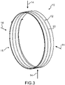
figure 3 est une vue similaire à celle de lafigure 1 , montrant encore un autre mode de réalisation de l'invention. - On a représenté aux figures une partie d'un système d'échange de chaleur 10 pour une turbomachine configurée avec une entrée d'air radiale, par exemple une turbomachine d'aéronef.
- La turbomachine comporte une pluralité de composants et organes qui s'échauffent lors du fonctionnement de la turbomachine, et qui ont besoin d'être refroidis ou d'être lubrifiés de manière continue.
- Pour cela, la turbomachine comporte un circuit fluidique principal qui alimente tous les composants et organes de la turbomachine avec un fluide qui est apte à les lubrifier ou refroidir.
- Le circuit fluidique principal est associé au système d'échange de chaleur 10 représenté aux figures, qui permet de refroidir le fluide qui a circulé au travers de ces composants et organes.
- Le système d'échange de chaleur 10 comporte un circuit fluidique 12 qui est raccordé au circuit fluidique principal ou bien qui constitue celui-ci et il est configuré pour qu'un échange de chaleur puisse avoir lieu entre le fluide chaud et une source froide 14.
- Pour cela, le système d'échange de chaleur 10 est configuré pour mettre en contact thermiquement le circuit fluidique 12 avec la source froide 14.
- Ici, la source froide 14 consiste en un flux d'air, par exemple le flux d'air qui est admis dans la turbomachine. Ce flux d'air est à une température proche de la température extérieur ambiante, qui peut être très basse, surtout lorsque l'aéronef vole à haute altitude.
- Pour céder de la chaleur vers le flux d'air 14 admis à partir du fluide du circuit fluidique 12, le système d'échange de chaleur 10 comporte une structure ajourée 16 comportant une pluralité d'ouvertures 15 qui sont traversées par le flux d'air 14 et qui est en contact thermique avec le fluide du circuit fluidique.
- De préférence, la structure ajourée 16 du système d'échange de chaleur 10 est chauffée par le fluide chaud, ce qui empêche l'accrétion, ou l'accumulation de cristaux de glace sur celle-ci, au niveau de l'entrée d'air de la turbomachine, lorsque l'aéronef vole dans des conditions extérieures givrantes.
- Ainsi, l'échange de chaleur entre le fluide chaud circulant dans le circuit fluidique 12 et le flux d'air traversant la structure ajourée 16 permet à la fois de refroidir le fluide et de réchauffer la structure ajourée 16 pour limiter l'accrétion de cristaux de glace.
- Pour échanger de la chaleur avec le fluide, la structure ajourée 16 est conçue pour pouvoir être traversée par le fluide chaud.
- A cet effet, selon un premier mode de réalisation représenté à la
figure 1 , la structure ajourée 16 consiste en un élément creux, par exemple réalisée par l'assemblage de deux plaques elles-mêmes ajourées, qui est traversée par le fluide chaud. - Ici, la structure ajourée 16 est de forme cylindrique de révolution, et elle est raccordée au circuit fluidique 12 à ses deux extrémités axiales. Le flux d'air traverse la structure ajourée 16 radialement, par rapport à son axe principal A.
- La structure ajourée 16 consiste en un assemblage de deux plaques ajourées cylindriques coaxiales dans lesquelles de ouvertures 15, dont la forme est par exemple circulaire ou rectangulaire.
- La structure ajourée 16 peut consister en un système à double peau, dont la peau interne est en contact avec le fluide chaud et la peau externe en contact avec le flux d'air 14 admis.
- Une première extrémité axiale 16a de la structure ajourée est ouverte et forme une entrée pour le fluide chaud, la deuxième extrémité axiale 16b de la structure ajourée 16 est elle aussi ouverte et forme une sortie pour le fluide refroidi.
- Selon un autre mode de réalisation représenté à la
figure 2 , la structure ajourée 16 forme une grille qui est réalisée en partie à partir de tronçons 18 du circuit fluidique 12. - Ici aussi, la structure ajourée 16 est de forme cylindrique de révolution. Les tronçons 18 du circuit fluidique 12 sont tous parallèles à l'axe principal A de la structure ajourée 16 et ils sont répartis régulièrement ou non autour de l'axe principal A de la structure ajourée 16.
- Les tronçons 18 du circuit fluidique 12 constituent des éléments structurels de la structure ajourée 16, de sorte que le transfert de chaleur s'effectue par conduction de chaleur avec les autres composants de la structure ajourée 16 et par échange de chaleur directement avec le flux d'air 14.
- Selon une variante de réalisation, représentée à la
figure 3 , la structure ajourée 16 consiste en une grille et un tronçon 20 du circuit fluidique 12 forme un élément structurel de la structure ajourée 16. Ce tronçon 20 du circuit fluidique 12 est en forme d'un enroulement hélicoïdal coaxial à l'axe principal A de la structure ajourée 16. Selon une autre variante non représentée, la structure ajourée 16 comporte plusieurs tronçons 20 en forme d'enroulement hélicoïdal. - Il sera compris que l'invention n'est pas limitée à ces seuls modes de réalisation et que le système d'échange de chaleur 10 peut comporter une combinaison des modes de réalisation précédents.
- Par exemple, le système d'échange de chaleur 10 peut comporter une structure ajourée 16 en forme de grille constituée à partir de tronçons 18 parallèles à l'axe principal de la structure ajourée 16 et à partir d'au moins un tronçon 20 de forme hélicoïdale.
- Aussi, selon un mode de réalisation non représenté et qui ne fait pas partie de l'invention revendiquée, la structure ajourée 16 peut consister en une structure à double peau dont la peau externe est en contact avec le flux d'air 14 et qui comporte des tubes internes formés à partir de tronçons 18, 20 du circuit fluidique 12. Le transfert de chaleur entre la peau externe et les tubes interne s'effectuant par exemple par des ponts thermiques.
- Aussi, selon un autre mode de réalisation non représenté et qui ne fait pas partie de l'invention revendiquée, la structure ajourée 16 est en forme d'un anneau plan, c'est-à-dire ayant une entrée d'air axiale. Selon ce mode de réalisation, le, ou les tronçons du circuit fluidique 12 constitutifs de la structure ajourée 16 sont soit des tronçons rectilignes orientés radialement par rapport à l'axe principal de la structure ajourée 16, ou bien un ou plusieurs tronçons en forme de spirale centrée sur l'axe principal de la structure ajourée 16.
- Ou bien, lorsque la structure ajourée 16 en forme d'anneau plan consiste en un élément creux, elle est réalisée par l'assemblage de deux plaques ajourées planes parallèles et est ouverte à chacune de ses extrémités radiales interne et externe.
Claims (3)
- Système d'échange de chaleur (10) dans une turbomachine comprenant une pluralité d'organes et équipements à refroidir et/ou à lubrifier, ledit système comprenant un circuit fluidique (12) pour refroidir et/ou lubrifier lesdits équipements, ledit système d'échange de chaleur (10) étant configuré pour mettre ledit circuit fluidique (12) en contact thermique avec un fluide (14) jouant le rôle de source froide d'autre part,le système d'échange de chaleur (10) comportant une structure ajourée (16) en forme d'une grille réalisée à partir de plusieurs tronçons du circuit fluidique qui sont répartis dans la structure ajourée et qui est traversée par un flux d'air (14) d'admission de la turbomachine formant la source froide,caractérisé en ce que la structure ajourée est de forme cylindrique annulaire de révolution et est configurée pour être traversée radialement par le flux d'air (14) lors de l'utilisation.
- Système d'échange de chaleur (10) selon la revendication précédente, caractérisé en ce que la structure ajourée (16) comporte plusieurs tronçons (18) du circuit fluidique (12) parallèles entre eux et parallèles à l'axe principal A de la structure ajourée (16).
- Système d'échange de chaleur (10) selon l'une quelconque des revendications 1 ou 2, caractérisé en ce que la structure ajourée (16) comporte au moins un tronçon (20) du circuit fluidique (12) qui forme un enroulement sensiblement hélicoïdal coaxial à l'axe principal A de la structure ajourée (16).
Applications Claiming Priority (2)
| Application Number | Priority Date | Filing Date | Title |
|---|---|---|---|
| FR1451057A FR3017452B1 (fr) | 2014-02-11 | 2014-02-11 | Systeme echangeur de chaleur |
| PCT/FR2015/050316 WO2015121576A1 (fr) | 2014-02-11 | 2015-02-10 | Système échangeur de chaleur |
Publications (2)
| Publication Number | Publication Date |
|---|---|
| EP3105424A1 EP3105424A1 (fr) | 2016-12-21 |
| EP3105424B1 true EP3105424B1 (fr) | 2023-03-29 |
Family
ID=50780685
Family Applications (1)
| Application Number | Title | Priority Date | Filing Date |
|---|---|---|---|
| EP15706907.1A Active EP3105424B1 (fr) | 2014-02-11 | 2015-02-10 | Système d'échangeur de chaleur |
Country Status (6)
| Country | Link |
|---|---|
| US (1) | US10677165B2 (fr) |
| EP (1) | EP3105424B1 (fr) |
| CA (1) | CA2941662C (fr) |
| ES (1) | ES2942641T3 (fr) |
| FR (1) | FR3017452B1 (fr) |
| WO (1) | WO2015121576A1 (fr) |
Families Citing this family (1)
| Publication number | Priority date | Publication date | Assignee | Title |
|---|---|---|---|---|
| CN110107405B (zh) * | 2019-05-22 | 2021-05-28 | 江鹏 | 一种直升机发动机进气防护格栅 |
Citations (2)
| Publication number | Priority date | Publication date | Assignee | Title |
|---|---|---|---|---|
| GB626571A (en) * | 1945-08-17 | 1949-07-18 | Westinghouse Electric Int Co | Improvements in or relating to gas turbine power plants |
| EP1630358A2 (fr) * | 2004-08-26 | 2006-03-01 | United Technologies Corporation | Cadre de turbine à gaz avec réservoir intégré de fluide et échangeur de chaleur air/liquide |
Family Cites Families (16)
| Publication number | Priority date | Publication date | Assignee | Title |
|---|---|---|---|---|
| US2798361A (en) * | 1947-08-19 | 1957-07-09 | Continental Aviat & Eng Corp | Internal combustion engines |
| GB973401A (en) * | 1963-08-30 | 1964-10-28 | Rolls Royce | Gas turbine engine |
| US3477505A (en) * | 1967-07-13 | 1969-11-11 | Texaco Inc | Heat exchanger |
| US4187675A (en) * | 1977-10-14 | 1980-02-12 | The United States Of America As Represented By The Secretary Of The Air Force | Compact air-to-air heat exchanger for jet engine application |
| US7131612B2 (en) * | 2003-07-29 | 2006-11-07 | Pratt & Whitney Canada Corp. | Nacelle inlet lip anti-icing with engine oil |
| US8205426B2 (en) * | 2006-07-31 | 2012-06-26 | General Electric Company | Method and apparatus for operating gas turbine engines |
| US7823374B2 (en) * | 2006-08-31 | 2010-11-02 | General Electric Company | Heat transfer system and method for turbine engine using heat pipes |
| US7845159B2 (en) * | 2006-08-31 | 2010-12-07 | General Electric Company | Heat pipe-based cooling apparatus and method for turbine engine |
| US8210825B2 (en) * | 2007-05-11 | 2012-07-03 | Honeywell International Inc. | Heated engine nose cone using spiral channels |
| EP2339123B1 (fr) * | 2009-12-23 | 2013-07-10 | Techspace Aero S.A. | Paroi intérieure annulaire de la veine secondaire d'un turboréacteur et procédé d'assemblage d'une telle paroi |
| FR2958974B1 (fr) | 2010-04-16 | 2016-06-10 | Snecma | Moteur de turbine a gaz muni d'un echangeur de chaleur air-huile dans sa manche d'entree d'air |
| US9766019B2 (en) * | 2011-02-28 | 2017-09-19 | Pratt & Whitney Canada Corp. | Swirl reducing gas turbine engine recuperator |
| US9243563B2 (en) * | 2012-01-25 | 2016-01-26 | Honeywell International Inc. | Gas turbine engine in-board cooled cooling air system |
| US9109842B2 (en) * | 2012-02-24 | 2015-08-18 | Pratt & Whitney Canada Corp. | Fuel air heat exchanger |
| US20140216056A1 (en) * | 2012-09-28 | 2014-08-07 | United Technologies Corporation | Heat exchange module for a turbine engine |
| US9677474B2 (en) * | 2013-11-18 | 2017-06-13 | Unison Industries, Llc | Surface cooler support mechanism |
-
2014
- 2014-02-11 FR FR1451057A patent/FR3017452B1/fr active Active
-
2015
- 2015-02-10 WO PCT/FR2015/050316 patent/WO2015121576A1/fr not_active Ceased
- 2015-02-10 EP EP15706907.1A patent/EP3105424B1/fr active Active
- 2015-02-10 US US15/117,904 patent/US10677165B2/en active Active
- 2015-02-10 CA CA2941662A patent/CA2941662C/fr active Active
- 2015-02-10 ES ES15706907T patent/ES2942641T3/es active Active
Patent Citations (2)
| Publication number | Priority date | Publication date | Assignee | Title |
|---|---|---|---|---|
| GB626571A (en) * | 1945-08-17 | 1949-07-18 | Westinghouse Electric Int Co | Improvements in or relating to gas turbine power plants |
| EP1630358A2 (fr) * | 2004-08-26 | 2006-03-01 | United Technologies Corporation | Cadre de turbine à gaz avec réservoir intégré de fluide et échangeur de chaleur air/liquide |
Also Published As
| Publication number | Publication date |
|---|---|
| CA2941662A1 (fr) | 2015-08-20 |
| CA2941662C (fr) | 2022-05-31 |
| ES2942641T3 (es) | 2023-06-05 |
| FR3017452B1 (fr) | 2019-05-24 |
| US10677165B2 (en) | 2020-06-09 |
| FR3017452A1 (fr) | 2015-08-14 |
| WO2015121576A1 (fr) | 2015-08-20 |
| EP3105424A1 (fr) | 2016-12-21 |
| US20160369699A1 (en) | 2016-12-22 |
Similar Documents
| Publication | Publication Date | Title |
|---|---|---|
| EP2435680B1 (fr) | Dispositif de refroidissement de fluides pour propulseur à turbomachine | |
| EP2472067B1 (fr) | Intégration d'un échangeur de chaleur surfacique avec débit d'air régulé dans un moteur d'avion | |
| FR3027624A1 (fr) | Circuit de degivrage d'une levre d'entree d'air d'un ensemble propulsif d'aeronef | |
| EP2510284B1 (fr) | Chambre de combustion pour turbomachine | |
| FR3001253A1 (fr) | Systeme regule de refroidissement d'huile d'un turboreacteur avec degivrage de la nacelle | |
| EP2815979B1 (fr) | Système de chauffage de l'habitacle d'un aéronef muni d'un échangeur thermique annulaire autour de la tuyère d'échappement | |
| FR3065490A1 (fr) | Ensemble propulsif pour aeronef comportant des echangeurs de chaleur air-liquide | |
| FR3001199A1 (fr) | Capot de moteur incorporant un circuit de ventilation d'equipement | |
| FR3002978A1 (fr) | Nacelle equipee d’un circuit de refroidissement d’huile a echangeur intermediaire | |
| EP3146157A1 (fr) | Rotor de turbine pour un moteur a turbine a gaz | |
| EP3487764B1 (fr) | Nacelle de turbomoteur comportant un dispositif de refroidissement | |
| EP3781882A1 (fr) | Dispositif de conditionnement thermique pour véhicule automobile | |
| EP4055259A1 (fr) | Echangeur de chaleur comportant une paroi perturbatrice à générateurs de turbulence creux | |
| CA2941662C (fr) | Systeme echangeur de chaleur | |
| EP3224463B1 (fr) | Agencements à entrée d'air et piège de corps étrangers dans un ensemble propulsif d'aéronef | |
| FR3039208A1 (fr) | Degivrage d’une levre d’entree d’air et refroidissement d’un carter de turbine d’un ensemble propulsif d’aeronef | |
| FR3089496A1 (fr) | Groupe propulseur d’aéronef à ingestion de couche limite comportant un moteur électrique et un système de refroidissement en partie disposé dans le cône de sortie | |
| FR3015654A1 (fr) | Echangeur de chaleur d'une turbomachine | |
| FR3003024A1 (fr) | Echangeur de chaleur d'une turbomachine | |
| FR3058459A1 (fr) | Dispositif de refroidissement pour une turbine d'une turbomachine | |
| EP4508320A1 (fr) | Turbomachine d'aeronef a plusieurs flux | |
| EP4441351B1 (fr) | Échangeur de chaleur air-huile avec by-pass pour turbomachine | |
| FR3009340A1 (fr) | Ventilation d'un equipement de turbomachine | |
| FR3023587A1 (fr) | Turbomachine a systeme de refroidissement autonome d'equipements. | |
| FR3044715A1 (fr) | Circuit de refroidissement d'un fluide chaud dans une turbomachine comprenant un dispositif de pre-refroidissement du fluide chaud |
Legal Events
| Date | Code | Title | Description |
|---|---|---|---|
| PUAI | Public reference made under article 153(3) epc to a published international application that has entered the european phase |
Free format text: ORIGINAL CODE: 0009012 |
|
| STAA | Information on the status of an ep patent application or granted ep patent |
Free format text: STATUS: REQUEST FOR EXAMINATION WAS MADE |
|
| 17P | Request for examination filed |
Effective date: 20160829 |
|
| AK | Designated contracting states |
Kind code of ref document: A1 Designated state(s): AL AT BE BG CH CY CZ DE DK EE ES FI FR GB GR HR HU IE IS IT LI LT LU LV MC MK MT NL NO PL PT RO RS SE SI SK SM TR |
|
| AX | Request for extension of the european patent |
Extension state: BA ME |
|
| DAX | Request for extension of the european patent (deleted) | ||
| STAA | Information on the status of an ep patent application or granted ep patent |
Free format text: STATUS: EXAMINATION IS IN PROGRESS |
|
| 17Q | First examination report despatched |
Effective date: 20190315 |
|
| GRAP | Despatch of communication of intention to grant a patent |
Free format text: ORIGINAL CODE: EPIDOSNIGR1 |
|
| STAA | Information on the status of an ep patent application or granted ep patent |
Free format text: STATUS: GRANT OF PATENT IS INTENDED |
|
| INTG | Intention to grant announced |
Effective date: 20220923 |
|
| GRAS | Grant fee paid |
Free format text: ORIGINAL CODE: EPIDOSNIGR3 |
|
| GRAA | (expected) grant |
Free format text: ORIGINAL CODE: 0009210 |
|
| STAA | Information on the status of an ep patent application or granted ep patent |
Free format text: STATUS: THE PATENT HAS BEEN GRANTED |
|
| AK | Designated contracting states |
Kind code of ref document: B1 Designated state(s): AL AT BE BG CH CY CZ DE DK EE ES FI FR GB GR HR HU IE IS IT LI LT LU LV MC MK MT NL NO PL PT RO RS SE SI SK SM TR |
|
| REG | Reference to a national code |
Ref country code: GB Ref legal event code: FG4D Free format text: NOT ENGLISH |
|
| REG | Reference to a national code |
Ref country code: CH Ref legal event code: EP |
|
| REG | Reference to a national code |
Ref country code: DE Ref legal event code: R096 Ref document number: 602015082953 Country of ref document: DE |
|
| REG | Reference to a national code |
Ref country code: AT Ref legal event code: REF Ref document number: 1556799 Country of ref document: AT Kind code of ref document: T Effective date: 20230415 |
|
| REG | Reference to a national code |
Ref country code: IE Ref legal event code: FG4D Free format text: LANGUAGE OF EP DOCUMENT: FRENCH |
|
| REG | Reference to a national code |
Ref country code: ES Ref legal event code: FG2A Ref document number: 2942641 Country of ref document: ES Kind code of ref document: T3 Effective date: 20230605 |
|
| REG | Reference to a national code |
Ref country code: LT Ref legal event code: MG9D |
|
| PG25 | Lapsed in a contracting state [announced via postgrant information from national office to epo] |
Ref country code: RS Free format text: LAPSE BECAUSE OF FAILURE TO SUBMIT A TRANSLATION OF THE DESCRIPTION OR TO PAY THE FEE WITHIN THE PRESCRIBED TIME-LIMIT Effective date: 20230329 Ref country code: NO Free format text: LAPSE BECAUSE OF FAILURE TO SUBMIT A TRANSLATION OF THE DESCRIPTION OR TO PAY THE FEE WITHIN THE PRESCRIBED TIME-LIMIT Effective date: 20230629 Ref country code: LV Free format text: LAPSE BECAUSE OF FAILURE TO SUBMIT A TRANSLATION OF THE DESCRIPTION OR TO PAY THE FEE WITHIN THE PRESCRIBED TIME-LIMIT Effective date: 20230329 Ref country code: LT Free format text: LAPSE BECAUSE OF FAILURE TO SUBMIT A TRANSLATION OF THE DESCRIPTION OR TO PAY THE FEE WITHIN THE PRESCRIBED TIME-LIMIT Effective date: 20230329 Ref country code: HR Free format text: LAPSE BECAUSE OF FAILURE TO SUBMIT A TRANSLATION OF THE DESCRIPTION OR TO PAY THE FEE WITHIN THE PRESCRIBED TIME-LIMIT Effective date: 20230329 |
|
| REG | Reference to a national code |
Ref country code: NL Ref legal event code: MP Effective date: 20230329 |
|
| REG | Reference to a national code |
Ref country code: AT Ref legal event code: MK05 Ref document number: 1556799 Country of ref document: AT Kind code of ref document: T Effective date: 20230329 |
|
| PG25 | Lapsed in a contracting state [announced via postgrant information from national office to epo] |
Ref country code: SE Free format text: LAPSE BECAUSE OF FAILURE TO SUBMIT A TRANSLATION OF THE DESCRIPTION OR TO PAY THE FEE WITHIN THE PRESCRIBED TIME-LIMIT Effective date: 20230329 Ref country code: NL Free format text: LAPSE BECAUSE OF FAILURE TO SUBMIT A TRANSLATION OF THE DESCRIPTION OR TO PAY THE FEE WITHIN THE PRESCRIBED TIME-LIMIT Effective date: 20230329 Ref country code: GR Free format text: LAPSE BECAUSE OF FAILURE TO SUBMIT A TRANSLATION OF THE DESCRIPTION OR TO PAY THE FEE WITHIN THE PRESCRIBED TIME-LIMIT Effective date: 20230630 Ref country code: FI Free format text: LAPSE BECAUSE OF FAILURE TO SUBMIT A TRANSLATION OF THE DESCRIPTION OR TO PAY THE FEE WITHIN THE PRESCRIBED TIME-LIMIT Effective date: 20230329 |
|
| PG25 | Lapsed in a contracting state [announced via postgrant information from national office to epo] |
Ref country code: SM Free format text: LAPSE BECAUSE OF FAILURE TO SUBMIT A TRANSLATION OF THE DESCRIPTION OR TO PAY THE FEE WITHIN THE PRESCRIBED TIME-LIMIT Effective date: 20230329 Ref country code: RO Free format text: LAPSE BECAUSE OF FAILURE TO SUBMIT A TRANSLATION OF THE DESCRIPTION OR TO PAY THE FEE WITHIN THE PRESCRIBED TIME-LIMIT Effective date: 20230329 Ref country code: PT Free format text: LAPSE BECAUSE OF FAILURE TO SUBMIT A TRANSLATION OF THE DESCRIPTION OR TO PAY THE FEE WITHIN THE PRESCRIBED TIME-LIMIT Effective date: 20230731 Ref country code: EE Free format text: LAPSE BECAUSE OF FAILURE TO SUBMIT A TRANSLATION OF THE DESCRIPTION OR TO PAY THE FEE WITHIN THE PRESCRIBED TIME-LIMIT Effective date: 20230329 Ref country code: AT Free format text: LAPSE BECAUSE OF FAILURE TO SUBMIT A TRANSLATION OF THE DESCRIPTION OR TO PAY THE FEE WITHIN THE PRESCRIBED TIME-LIMIT Effective date: 20230329 |
|
| PG25 | Lapsed in a contracting state [announced via postgrant information from national office to epo] |
Ref country code: SK Free format text: LAPSE BECAUSE OF FAILURE TO SUBMIT A TRANSLATION OF THE DESCRIPTION OR TO PAY THE FEE WITHIN THE PRESCRIBED TIME-LIMIT Effective date: 20230329 Ref country code: PL Free format text: LAPSE BECAUSE OF FAILURE TO SUBMIT A TRANSLATION OF THE DESCRIPTION OR TO PAY THE FEE WITHIN THE PRESCRIBED TIME-LIMIT Effective date: 20230329 Ref country code: IS Free format text: LAPSE BECAUSE OF FAILURE TO SUBMIT A TRANSLATION OF THE DESCRIPTION OR TO PAY THE FEE WITHIN THE PRESCRIBED TIME-LIMIT Effective date: 20230729 |
|
| REG | Reference to a national code |
Ref country code: DE Ref legal event code: R097 Ref document number: 602015082953 Country of ref document: DE |
|
| PG25 | Lapsed in a contracting state [announced via postgrant information from national office to epo] |
Ref country code: DK Free format text: LAPSE BECAUSE OF FAILURE TO SUBMIT A TRANSLATION OF THE DESCRIPTION OR TO PAY THE FEE WITHIN THE PRESCRIBED TIME-LIMIT Effective date: 20230329 Ref country code: CZ Free format text: LAPSE BECAUSE OF FAILURE TO SUBMIT A TRANSLATION OF THE DESCRIPTION OR TO PAY THE FEE WITHIN THE PRESCRIBED TIME-LIMIT Effective date: 20230329 |
|
| PLBE | No opposition filed within time limit |
Free format text: ORIGINAL CODE: 0009261 |
|
| STAA | Information on the status of an ep patent application or granted ep patent |
Free format text: STATUS: NO OPPOSITION FILED WITHIN TIME LIMIT |
|
| 26N | No opposition filed |
Effective date: 20240103 |
|
| PG25 | Lapsed in a contracting state [announced via postgrant information from national office to epo] |
Ref country code: SI Free format text: LAPSE BECAUSE OF FAILURE TO SUBMIT A TRANSLATION OF THE DESCRIPTION OR TO PAY THE FEE WITHIN THE PRESCRIBED TIME-LIMIT Effective date: 20230329 |
|
| PG25 | Lapsed in a contracting state [announced via postgrant information from national office to epo] |
Ref country code: SI Free format text: LAPSE BECAUSE OF FAILURE TO SUBMIT A TRANSLATION OF THE DESCRIPTION OR TO PAY THE FEE WITHIN THE PRESCRIBED TIME-LIMIT Effective date: 20230329 Ref country code: IT Free format text: LAPSE BECAUSE OF FAILURE TO SUBMIT A TRANSLATION OF THE DESCRIPTION OR TO PAY THE FEE WITHIN THE PRESCRIBED TIME-LIMIT Effective date: 20230329 |
|
| PG25 | Lapsed in a contracting state [announced via postgrant information from national office to epo] |
Ref country code: MC Free format text: LAPSE BECAUSE OF FAILURE TO SUBMIT A TRANSLATION OF THE DESCRIPTION OR TO PAY THE FEE WITHIN THE PRESCRIBED TIME-LIMIT Effective date: 20230329 |
|
| REG | Reference to a national code |
Ref country code: CH Ref legal event code: PL |
|
| PG25 | Lapsed in a contracting state [announced via postgrant information from national office to epo] |
Ref country code: LU Free format text: LAPSE BECAUSE OF NON-PAYMENT OF DUE FEES Effective date: 20240210 |
|
| PG25 | Lapsed in a contracting state [announced via postgrant information from national office to epo] |
Ref country code: CH Free format text: LAPSE BECAUSE OF NON-PAYMENT OF DUE FEES Effective date: 20240229 |
|
| PG25 | Lapsed in a contracting state [announced via postgrant information from national office to epo] |
Ref country code: LU Free format text: LAPSE BECAUSE OF NON-PAYMENT OF DUE FEES Effective date: 20240210 Ref country code: CH Free format text: LAPSE BECAUSE OF NON-PAYMENT OF DUE FEES Effective date: 20240229 |
|
| PG25 | Lapsed in a contracting state [announced via postgrant information from national office to epo] |
Ref country code: BG Free format text: LAPSE BECAUSE OF FAILURE TO SUBMIT A TRANSLATION OF THE DESCRIPTION OR TO PAY THE FEE WITHIN THE PRESCRIBED TIME-LIMIT Effective date: 20230329 |
|
| PG25 | Lapsed in a contracting state [announced via postgrant information from national office to epo] |
Ref country code: BG Free format text: LAPSE BECAUSE OF FAILURE TO SUBMIT A TRANSLATION OF THE DESCRIPTION OR TO PAY THE FEE WITHIN THE PRESCRIBED TIME-LIMIT Effective date: 20230329 |
|
| REG | Reference to a national code |
Ref country code: BE Ref legal event code: MM Effective date: 20240229 |
|
| PG25 | Lapsed in a contracting state [announced via postgrant information from national office to epo] |
Ref country code: BE Free format text: LAPSE BECAUSE OF NON-PAYMENT OF DUE FEES Effective date: 20240229 |
|
| PG25 | Lapsed in a contracting state [announced via postgrant information from national office to epo] |
Ref country code: IE Free format text: LAPSE BECAUSE OF NON-PAYMENT OF DUE FEES Effective date: 20240210 |
|
| PG25 | Lapsed in a contracting state [announced via postgrant information from national office to epo] |
Ref country code: IE Free format text: LAPSE BECAUSE OF NON-PAYMENT OF DUE FEES Effective date: 20240210 Ref country code: BE Free format text: LAPSE BECAUSE OF NON-PAYMENT OF DUE FEES Effective date: 20240229 |
|
| PG25 | Lapsed in a contracting state [announced via postgrant information from national office to epo] |
Ref country code: CY Free format text: LAPSE BECAUSE OF FAILURE TO SUBMIT A TRANSLATION OF THE DESCRIPTION OR TO PAY THE FEE WITHIN THE PRESCRIBED TIME-LIMIT; INVALID AB INITIO Effective date: 20150210 |
|
| PG25 | Lapsed in a contracting state [announced via postgrant information from national office to epo] |
Ref country code: HU Free format text: LAPSE BECAUSE OF FAILURE TO SUBMIT A TRANSLATION OF THE DESCRIPTION OR TO PAY THE FEE WITHIN THE PRESCRIBED TIME-LIMIT; INVALID AB INITIO Effective date: 20150210 |
|
| PG25 | Lapsed in a contracting state [announced via postgrant information from national office to epo] |
Ref country code: TR Free format text: LAPSE BECAUSE OF FAILURE TO SUBMIT A TRANSLATION OF THE DESCRIPTION OR TO PAY THE FEE WITHIN THE PRESCRIBED TIME-LIMIT Effective date: 20230329 |
|
| PGFP | Annual fee paid to national office [announced via postgrant information from national office to epo] |
Ref country code: GB Payment date: 20260219 Year of fee payment: 12 |
|
| PGFP | Annual fee paid to national office [announced via postgrant information from national office to epo] |
Ref country code: ES Payment date: 20260319 Year of fee payment: 12 |
|
| PGFP | Annual fee paid to national office [announced via postgrant information from national office to epo] |
Ref country code: DE Payment date: 20260217 Year of fee payment: 12 |
|
| PGFP | Annual fee paid to national office [announced via postgrant information from national office to epo] |
Ref country code: FR Payment date: 20260213 Year of fee payment: 12 |