EP3104626A1 - Hearing aid having a magnetic switch integrated into a microphone - Google Patents
Hearing aid having a magnetic switch integrated into a microphone Download PDFInfo
- Publication number
- EP3104626A1 EP3104626A1 EP15171725.3A EP15171725A EP3104626A1 EP 3104626 A1 EP3104626 A1 EP 3104626A1 EP 15171725 A EP15171725 A EP 15171725A EP 3104626 A1 EP3104626 A1 EP 3104626A1
- Authority
- EP
- European Patent Office
- Prior art keywords
- electroacoustic transducer
- switch
- hearing aid
- housing
- magnetically actuatable
- Prior art date
- Legal status (The legal status is an assumption and is not a legal conclusion. Google has not performed a legal analysis and makes no representation as to the accuracy of the status listed.)
- Withdrawn
Links
Images

Classifications
-
- H—ELECTRICITY
- H04—ELECTRIC COMMUNICATION TECHNIQUE
- H04R—LOUDSPEAKERS, MICROPHONES, GRAMOPHONE PICK-UPS OR LIKE ACOUSTIC ELECTROMECHANICAL TRANSDUCERS; ELECTRIC HEARING AIDS; PUBLIC ADDRESS SYSTEMS
- H04R25/00—Electric hearing aids
- H04R25/60—Mounting or interconnection of hearing aid parts, e.g. inside tips, housings or to ossicles
- H04R25/603—Mounting or interconnection of hearing aid parts, e.g. inside tips, housings or to ossicles of mechanical or electronic switches or control elements
-
- H—ELECTRICITY
- H04—ELECTRIC COMMUNICATION TECHNIQUE
- H04R—LOUDSPEAKERS, MICROPHONES, GRAMOPHONE PICK-UPS OR LIKE ACOUSTIC ELECTROMECHANICAL TRANSDUCERS; ELECTRIC HEARING AIDS; PUBLIC ADDRESS SYSTEMS
- H04R2225/00—Details of deaf aids covered by H04R25/00, not provided for in any of its subgroups
- H04R2225/021—Behind the ear [BTE] hearing aids
-
- H—ELECTRICITY
- H04—ELECTRIC COMMUNICATION TECHNIQUE
- H04R—LOUDSPEAKERS, MICROPHONES, GRAMOPHONE PICK-UPS OR LIKE ACOUSTIC ELECTROMECHANICAL TRANSDUCERS; ELECTRIC HEARING AIDS; PUBLIC ADDRESS SYSTEMS
- H04R2225/00—Details of deaf aids covered by H04R25/00, not provided for in any of its subgroups
- H04R2225/023—Completely in the canal [CIC] hearing aids
-
- H—ELECTRICITY
- H04—ELECTRIC COMMUNICATION TECHNIQUE
- H04R—LOUDSPEAKERS, MICROPHONES, GRAMOPHONE PICK-UPS OR LIKE ACOUSTIC ELECTROMECHANICAL TRANSDUCERS; ELECTRIC HEARING AIDS; PUBLIC ADDRESS SYSTEMS
- H04R2225/00—Details of deaf aids covered by H04R25/00, not provided for in any of its subgroups
- H04R2225/025—In the ear hearing aids [ITE] hearing aids
-
- H—ELECTRICITY
- H04—ELECTRIC COMMUNICATION TECHNIQUE
- H04R—LOUDSPEAKERS, MICROPHONES, GRAMOPHONE PICK-UPS OR LIKE ACOUSTIC ELECTROMECHANICAL TRANSDUCERS; ELECTRIC HEARING AIDS; PUBLIC ADDRESS SYSTEMS
- H04R2225/00—Details of deaf aids covered by H04R25/00, not provided for in any of its subgroups
- H04R2225/57—Aspects of electrical interconnection between hearing aid parts
-
- H—ELECTRICITY
- H04—ELECTRIC COMMUNICATION TECHNIQUE
- H04R—LOUDSPEAKERS, MICROPHONES, GRAMOPHONE PICK-UPS OR LIKE ACOUSTIC ELECTROMECHANICAL TRANSDUCERS; ELECTRIC HEARING AIDS; PUBLIC ADDRESS SYSTEMS
- H04R2225/00—Details of deaf aids covered by H04R25/00, not provided for in any of its subgroups
- H04R2225/61—Aspects relating to mechanical or electronic switches or control elements, e.g. functioning
-
- H—ELECTRICITY
- H04—ELECTRIC COMMUNICATION TECHNIQUE
- H04R—LOUDSPEAKERS, MICROPHONES, GRAMOPHONE PICK-UPS OR LIKE ACOUSTIC ELECTROMECHANICAL TRANSDUCERS; ELECTRIC HEARING AIDS; PUBLIC ADDRESS SYSTEMS
- H04R25/00—Electric hearing aids
- H04R25/60—Mounting or interconnection of hearing aid parts, e.g. inside tips, housings or to ossicles
- H04R25/609—Mounting or interconnection of hearing aid parts, e.g. inside tips, housings or to ossicles of circuitry
Definitions
- the present invention relates to a hearing aid, particularly to a hearing aid in which a magnetically actuatable switch and an electroacoustic transducer form a module that comprises at least one electric contact that is shared between said electroacoustic transducer and said magnetically actuatable switch.
- hearing aid shall be understood as a device to be worn at the vicinity or directly within the ear of a person to improve the individual hearing capacity of this person. Such an improvement may include the prevention of the receiving of certain acoustic signals in terms of ear protection.
- hearing devices can be worn, for instance, behind the ear (BTE), within the ear (ITE) or completely within the ear (CIC).
- BTE behind the ear
- ITE within the ear
- CIC completely within the ear
- IIC invisible in the canal
- Hearing aids normally comprise at least one microphone as electroacoustic input transducer; at least one speaker - usually called receiver - as electroacoustic output transducer; and an electronic signal processing circuitry, connected with said microphone and said speaker, for the processing and manipulation of electronic signals.
- This electronic signal processing circuitry may comprise analogue or digital signal processing devices. Said elements are usually arranged within at least one main case or shell of the hearing device.
- the electronic signal processing circuit performs various signal processing functions. Such signal processing functions can include amplification, background noise reduction, tone control, etc.
- the signal processing functions of current hearing aids can be provided with the option of adjustable operational modes or parameters or characteristics, thus allowing user customization of the hearing aids or their prompt adaptive response to given, changeable environment conditions.
- Some of the operational modes or parameters or characteristics which can be programmed to be modifiable include selective signal input, tone control or volume control. Selective signal input can be implemented, for instance whenever a phone is used in connection with a hearing aid, by switching from a first operational mode wherein the microphone acoustically receives the sound to a second operational mode wherein, instead, a coil electromagnetically picks up the sound, normally via a tele-coil.
- a manual switch can be provided which allows to achieve mode or characteristic control by manual manipulation of the switch by the user. Touching and displacing by the hearing aid wearer of such manual switches can enable some adjustment.
- magnetically activated switches are made cooperate with corresponding magnetic actuators.
- magnetic actuators are held by a user and are brought by the user in the effective proximity of hearing aid.
- the magnetic switches are conceived in a way that, when sensing a magnetic field threshold and/or change thereof, they determine a related mode, parameter or characteristic switching.
- magnetic switches are incorporated in hearing devices by mounting them on circuit boards in positions such that they remain physically separate from other electromagnetic components.
- state of the art magnetic switches have an own housing and are positioned on circuit boards or substrates in respective locations which are spatially distinct from those allocated to other hearing aid components such as electroacoustic transducers or electrical signal processing elements.
- Document WO 96/07295 A1 shows a hearing aid device whose components each have respective, spatially separate housings, as well as distinct signal processing and control processing circuitries, as it can be derived from Figure 3 , for instance.
- the configuration is such that
- the layout of the hearing aid devices designed according to the teachings of WO 96/07295 is such that additional space within the main casing or shell is required if mounting of a magnetic switch is envisaged.
- This additional space requirement brings about the necessity of providing the hearing aid device with a bulkier main casing or shell, which proves to be, as above explained, a major drawback in the relevant technical field.
- dedicated additional wiring such as so-called litzwires, for connecting the switch configured to automatically adjust the hearing aid's operational modes are usually free-floating within a hearing aid's main casing or shell.
- the resulting, somehow chaotic distribution of wires within the main casing or shell is strongly undesirable and adversely affects case or shell accessibility.
- the proliferating of wires within the case or shell entails complications in carrying out the manufacturing steps, including gluing or generally affixing the sensor to a faceplate or support.
- chaotic wiring can cause unpredictable mechanical feedback problems.
- the assembly configuration of the hearing aids presently in use is such that faceplate space -or the space taken up by the electric components of such devices- is not rationalized, particularly when it is required that the hearing aids include a magnetic switch, to achieve the automatic or semi-automatic adjustment of the operational parameters of the signal processing circuitry. None of the current hearing aids effectively solves the problem of integrating such magnetic switches in a way that the incorporation thereof does not adversely result in additional space needed within the casing or shell of the hearing aids.
- a major objective of the present invention is to provide a compact design for a hearing aid that exploits at the best the space available within the device's casing or shell.
- the inventive solution basically requires to combine an electroacoustic transducer with a magnetic switch in a single module in which the transducer and the switch share electric contacts, e.g. power supply contacts.
- the physical coupling of a magnetically actuatable switch with an electroacoustic transducer according to the present invention reduces advantageously the number of production steps required to effectively secure and connect components within a hearing aid's casing or shell and the number of wires necessary to establish an electrical connection of such switch to the other components. As a consequence, also repair processes are simplified.
- a Behind-the-Ear (BTE) hearing aid 10 normally comprises a casing 2 which accommodates a multiplicity of electric components.
- a casing 2 for ITEs, CICs and IICs can alternatively be designated as a shell.
- Such a multiplicity of electric components generally comprises an energy storage device 6, such as a battery or accumulator, which is accommodated in a respective compartment.
- a hearing aid such as the one of Figure 1 usually comprises a first electroacoustic transducer 1, such as a microphone, for converting sound waves into electrical signals.
- the casing 2 of the hearing device usually comprises a second electroacoustic transducer 1', namely a receiver, for converting electrical signals into sound waves compatible with human hearing and reception thereof by the hearing aid's user.
- a signal processing circuitry 3 typically comprising a processor - in digital hearing aids also called digital signal processor (DSP) - is configured to receive from an electroacoustic transducer 1, e.g. a microphone, an electrical input signal. The electrical input signal results from the conversion of input sound waves into electrical signals.
- the signal processing circuitry 3 provides an electroacoustic transducer 1', e.g. a receiver, with an electric output signal. The receiver converts the electrical output signals into sound waves usually transmitted to the user's eardrum.
- a conventional Behind-the-Ear (BTE) hearing aid 10 as portrayed in Figure 1A can also comprise a manual switch 9 allowing the user to manually change some signal processing settings sent to the signal processing circuitry 3.
- Such manual switches are practical and effective only to the extent that the corresponding hearing aids provide enough accessibility to allow engagement by a user's finger or similar with some activation means on the switches, such as a lever or a push button.
- Completely in the ear (CIC) hearing aids in particular, as well as within the ear (ITE) hearing aids for some designs are generally positioned in a way that manual switches do not represent a valid solution.
- Analogous considerations apply, of course, to so-called invisible in the canal (IIC) hearing aids.
- Even BTE hearing aids as shown in Figure 1A can additionally comprise non-manually actuated switches, for instance magnetic switches, for adjusting the operational parameters of the signal processing circuitry 3.
- FIG. 1B schematically represents a known within the ear (ITE) hearing aid 10 which, mutatis mutandis, comprises within a casing or shell 2 the same components described in connection with the example of Figure 1A .
- the settings and operational parameters of the signal processing circuitry 3 are substantially adjusted by a sensor or switch 4 which is not intended to be manually operated and can be, for instance, a magnetically actuatable switch instructing operational parameter changes from remote, following the detection of a corresponding change of an imparted magnetic field.
- switches for the automatic or semi-automatic adjustment of operational parameters of the signal processing circuitry 3, such as magnetic actuatable switches 4, are positioned within the casing 2 in respective housings which are disposed spatially separate with respect to the housings of all other hearing aid components.
- the housing of switches 4 is spatially decoupled and separate from that of input electroacoustic transducer 1 and/or output electroacoustic transducer 1'.
- a hearing aid according to the present invention comprises a casing 2, otherwise designated as shell, accommodating at least an electroacoustic transducer; signal processing circuitry 3 and a magnetically actuatable switch 4.
- the electroacoustic transducer can be a microphone 1; alternatively, it can be a receiver 1'.
- the hearing aid according to the present invention can comprise both a microphone 1 and a receiver 1'.
- an electroacoustic transducer can be also provided with both functionalities of a microphone and a receiver integrated into one component.
- a microphone can be any kind of microphone suitable to a hearing aid, such as for instance an electret condenser microphone or a silicon microphone, usually designated as MEMS microphone.
- the signal processing circuitry 3 typically comprises a processor, or DSP, and is configured to receive from the at least one electroacoustic transducer 1 an electrical input signal and/or to provide the at least one electroacoustic transducer 1' with an electric output signal.
- an electrical input signal typically is the result of a conversion of sound waves picked up by a microphone 1 into an electrical signal, to be further elaborated by the processing circuitry 3; whereas an electrical output signal transmitted from the processing circuitry 3 is used by a receiver 1' for conversion into sound waves optimized for the hearing aid's user.
- the magnetically actuatable switch 4 of the hearing aid according to the present invention can be, for example, any of a GMR switch; a TMR switch; an AMR switch; a reed switch or a Hall effect sensor.
- any type of magneto-resistive switch is in principle suitable to implement the magnetically actuatable switch 4 of the present invention.
- the hearing aid according to the present invention is structured in a way that the magnetically actuatable switch 4 and the electroacoustic transducer 1, 1' advantageously form a single module 50, as it is portrayed in Figure 2 .
- Figure 2 represents one preferred embodiment of the present invention wherein the electroacoustic transducer is a microphone 1.
- the at least one electroacoustic transducer can alternatively be a receiver 1', or even an electroacoustic transducer encompassing both the functions of a microphone and a receiver.
- the configuration is such that the single module 50 formed by the magnetically actuatable switch 4 and the electroacoustic transducer 1, 1' comprises at least one electric contact 8', 8" that is advantageously shared between the electroacoustic transducer 1, 1' and the magnetically actuatable switch 4.
- the one common module 50 as above defined preferably comprises a housing 5 of the electroacoustic transducer 1, 1'.
- the module 50 comprises the housing 5 of the microphone 1.
- the magnetically actuatable switch 4 such as a GMR sensor
- the magnetically actuatable switch 4 is placed directly onto the printed circuit board of the electroacoustic transducer 1, 1'.
- a silicon die of the GMR sensor is placed directly onto the printed circuit board of the microphone 1.
- the silicon die of the GMR sensor is placed directly onto the printed circuit board of the microphone 1, preferably such GMR die shares the same printed circuit board as a preamplifier of the microphone 1.
- the die of the GMR sensor can share the same printed circuit board as the MEMS' die.
- the printed circuit board of the microphone 1 itself is not conductive; this allows to advantageously achieve a gain in the detection power of a sensor such as a GMR sensor.
- a sound inlet of microphone 1 is indicated by reference number 7.
- the at least one contact 8', 8" shared between the electroacoustic transducer 1, 1' and the magnetically actuatable switch 4 can be advantageously positioned at the housing 5 of the single module 50.
- the shared electric contact 8', 8" can be configured to receive power for the electroacoustic transducer 1, 1' and for the magnetically actuatable switch 4; or it can be configured to form a common ground contact.
- the housing 5 in the single module 50 advantageously comprises an array of electric contacts 8', 8", 8m and 8s.
- Such an array of electric contacts 8', 8", 8m and 8s is preferably positioned at a contact area Ca of the housing 5 of the electroacoustic transducer 1, 1'.
- Electric contacts 8', 8", 8m and 8s can be, for example, in the form of solder pads.
- the contact area Ca incorporates at least common input electric contacts 8', 8" configured to receive power, both for the electroacoustic transducer 1, 1' and for the magnetically actuatable switch 4, from a power supply means such as a battery 6.
- the contact area Ca can also advantageously incorporate output electrical contacts for transmission of signals out of the electroacoustic transducer 1, 1' and out of the magnetic switch 4.
- one output electrical contact 8m is integrated in the housing 5 at the contact area Ca for outputting signals transmitted by the electroacoustic transducer 1, 1'; whereas a further output electrical contact 8s is integrated in the housing 5 at the contact area Ca for outputting signals transmitted by the magnetic switch 4.
- the module 50 formed by magnetically actuatable switch 4 and by electroacoustic transducer 1, 1' is designed in a way that the switch 4 is secured to a wall of the housing 5 of the electroacoustic transducer 1, 1'.
- the switch 4 can be secured to the housing 5 of the electroacoustic transducer 1, 1' by any suitable means of fixation or fastening.
- the switch 4 is fixed to a wall of the housing 5 of the electroacoustic transducer 1, 1'.
- the switch 4 can also be made integral with the housing 5, for instance by fixing it in the surrounding material of the housing 5, e.g. by embedding it in the housing's walls. Whatever the technique employed for securing the switch 4 to the housing 5, the resulting configuration will be such that at least one electric contact 8', 8" is shared between switch 4 and electroacoustic transducer 1, 1'.
- the magnetically actuatable switch 4 can be disposed internal to the housing 5 of the at least one electroacoustic transducer 1, 1'.
- the housing 5 of the electroacoustic transducer 1, 1' is made of a material that is magnetically conductive.
- the magnetic switch 4 can easily detect a change in magnetic field and, as a consequence, instruct by transmission of a proportional signal the adjustment of operational parameters of the signal processing circuitry 3 whenever a threshold magnetic field or the change thereof is detected.
- the housing 5 it is not an absolute requirement that the housing 5 be magnetically conductive in case the magnetically actuatable switch 4 is disposed in the housing.
- the overall configuration of a hearing aid according to the present invention is also substantially compatible with an embodiment wherein a magnetically actuatable switch 4 is positioned in a housing 5 of the electroacoustic transducer 1, 1' that is at least partially magnetically shielded.
- a magnetically actuatable switch 4 is positioned in a housing 5 of the electroacoustic transducer 1, 1' that is at least partially magnetically shielded.
- an opening can also be advantageously provided in the housing 5.
- the housing 5 can also advantageously be given a shape that biases the magnetic field in a way that the magnetic field is best detected by the magnetically actuatable switch 4.
- the magnetically actuatable switch 4 can be disposed external to the housing 5 of the electroacoustic transducer 1, 1'.
- the switch 4 can be fixed, for instance, to an external surface of a wall of the housing 5, in correspondence of the contact area Ca or adjacent thereto, the resulting configuration being anyhow such that at least one electric contact 8', 8" is shared between switch 4 and electroacoustic transducer 1, 1'.
- the body of the switch 4 can also be used to provide for a closure of the housing 5 of the electroacoustic transducer 1, 1'.
- a magnetically shielding element is interposed between the electroacoustic transducer 1, 1' and the magnetically actuatable switch 4.
- a magnetically shielding element advantageously ensures that the change in magnetic field used for activating the magnetic switch 4 does not overly affect the user-friendly functioning of the electroacoustic transducer 1, 1'.
- the entire housing 5 can be made of magnetically shielding material.
- just the most relevant portion of the housing 5 at the interface between switch 4 and transducer 1, 1' can be made of magnetically shielding material.
- the magnetically actuatable switch 4 is a GMR sensor.
- the latest models of GMR-sensors available on the market are extremely sensitive to changes of magnetic fields, to the point that GMR-sensors come to perceive even the Earth's magnetic field. Accordingly, the use of a GMR-sensor can limit to a minimum the interferences between magnetic fields applied to the magnetic switches and electroacoustic transducers such as microphones 1. If any residual interference withstands, this just gives an indication to the user of the fact that the actuation of the magnetic switch 4 by application of a given magnetic field has actually succeeded, at the most for the short timeframe employed for applying such magnetic field.
- the magnetically actuatable switch 4 can be equipped with a magnetic flux intensifier so as to enhance its capacity to detect even weak or very weak magnetic fields.
- the magnetically actuatable switch 4 and the electroacoustic transducer 1, 1' each maintain their respective functionality, but the spatial coupling between them allows to save on faceplate space taken up by components, which is crucial in the present technical field.
- magnetic switch 4 and electroacoustic transducer 1, 1' allows to save on number of required electrical connections and, proportionally, on number of wires required to connect the components of the hearing aid 10 between themselves and with a power supply, such as a battery 6.
Landscapes
- Health & Medical Sciences (AREA)
- General Health & Medical Sciences (AREA)
- Neurosurgery (AREA)
- Otolaryngology (AREA)
- Physics & Mathematics (AREA)
- Engineering & Computer Science (AREA)
- Acoustics & Sound (AREA)
- Signal Processing (AREA)
- Headphones And Earphones (AREA)
Abstract
This invention relates to a hearing aid (10) comprising a casing (2) accommodating an electroacoustic transducer (1, 1'); a signal processing circuitry (3), configured to receive from the at least an electroacoustic transducer (1) an electrical input signal and/or to provide said at least an electroacoustic transducer (1') with an electrical output signal; and a magnetically actuatable switch (4) for adjusting the operational parameters of the signal processing circuitry (3). The magnetically actuatable switch (4) and the electroacoustic transducer (1, 1') form together a single module (50) which comprises at least one electric contact (8', 8") that is shared between the at least an electroacoustic transducer (1, 1') and the magnetically actuatable switch (4).
Description
- The present invention relates to a hearing aid, particularly to a hearing aid in which a magnetically actuatable switch and an electroacoustic transducer form a module that comprises at least one electric contact that is shared between said electroacoustic transducer and said magnetically actuatable switch.
- The term hearing aid shall be understood as a device to be worn at the vicinity or directly within the ear of a person to improve the individual hearing capacity of this person. Such an improvement may include the prevention of the receiving of certain acoustic signals in terms of ear protection.
- In relation to their application and user indication, and according to the corresponding main solutions available on the market, such hearing devices can be worn, for instance, behind the ear (BTE), within the ear (ITE) or completely within the ear (CIC). The latest design developments have made available hearing devices that are even smaller than completely within the ear (CIC) devices, aptly named invisible in the canal (IIC) hearing aids.
- It will be recognized that the features of the present invention are substantially compatible with any style of hearing aids, including the abovementioned models, as well as with hearing aids which are eyewear-mounted, body-worn, etc.
- Hearing aids normally comprise at least one microphone as electroacoustic input transducer; at least one speaker - usually called receiver - as electroacoustic output transducer; and an electronic signal processing circuitry, connected with said microphone and said speaker, for the processing and manipulation of electronic signals. This electronic signal processing circuitry may comprise analogue or digital signal processing devices. Said elements are usually arranged within at least one main case or shell of the hearing device. The electronic signal processing circuit performs various signal processing functions. Such signal processing functions can include amplification, background noise reduction, tone control, etc.
- The signal processing functions of current hearing aids can be provided with the option of adjustable operational modes or parameters or characteristics, thus allowing user customization of the hearing aids or their prompt adaptive response to given, changeable environment conditions. Some of the operational modes or parameters or characteristics which can be programmed to be modifiable include selective signal input, tone control or volume control. Selective signal input can be implemented, for instance whenever a phone is used in connection with a hearing aid, by switching from a first operational mode wherein the microphone acoustically receives the sound to a second operational mode wherein, instead, a coil electromagnetically picks up the sound, normally via a tele-coil.
- Different kinds of switches are known in the prior art that can carry out an adjustment of the hearing aid operational modes or parameters or characteristics - whether in connection with the concurrent use of a telephone, of some other communication device or on account of other exigencies.
- For instance, particularly for BTE devices which are more accessible to a user but in some cases also for ITE and CIC devices, a manual switch can be provided which allows to achieve mode or characteristic control by manual manipulation of the switch by the user. Touching and displacing by the hearing aid wearer of such manual switches can enable some adjustment.
- Following more recent developments of the technology in the field of hearing aids, hand-operated switches, like levers or push-buttons, have proved not very practical for some of the new, smaller hearing aid models (especially for invisible in the canal devices, otherwise designated IIC) and several solutions have been proposed to implement mode switching and adjustment of operational parameters automatically, for instance by switches which are automatically and/or remotely activated when sensing a threshold magnetic field or the change thereof.
- In some known cases, for the purpose of carrying out such a magnetically induced adjustment, magnetically activated switches are made cooperate with corresponding magnetic actuators. Typically, magnetic actuators are held by a user and are brought by the user in the effective proximity of hearing aid. The magnetic switches are conceived in a way that, when sensing a magnetic field threshold and/or change thereof, they determine a related mode, parameter or characteristic switching.
- Particularly in hearing aid models wherein miniaturization is paramount, it is increasingly popular employing magnetic switches which can be activated without the need of manual intervention of the user on a switch interface directly located on the body of the device.
- According to current technologies, magnetic switches are incorporated in hearing devices by mounting them on circuit boards in positions such that they remain physically separate from other electromagnetic components.
Normally, state of the art magnetic switches have an own housing and are positioned on circuit boards or substrates in respective locations which are spatially distinct from those allocated to other hearing aid components such as electroacoustic transducers or electrical signal processing elements. - Document
WO 96/07295 A1 Figure 3 , for instance.
InWO 96/07295 - a microphone and a receiver, connected with each other via signal processing circuitry, on the one hand; and
- a magnetic switch, configured to be activated by a magnetic actuator to instruct the adjustment of operational parameters via a control processing circuitry, on the other hand,
- However, the layout of the hearing aid devices designed according to the teachings of
WO 96/07295 - Moreover, for a magnetic switch usually a power supply is needed. Therefore, additional dedicated wires for connection of the switch to the power supply need to be generally provided. Power supply wires connecting a power source, such as a battery or similar, to an additional switch result in further space requirements which are oftentimes not compliant with the miniaturization constraints that a usable and well-fitting hearing aid needs to satisfy.
- In addition to that, dedicated additional wiring, such as so-called litzwires, for connecting the switch configured to automatically adjust the hearing aid's operational modes are usually free-floating within a hearing aid's main casing or shell.
The resulting, somehow chaotic distribution of wires within the main casing or shell is strongly undesirable and adversely affects case or shell accessibility. Also, the proliferating of wires within the case or shell entails complications in carrying out the manufacturing steps, including gluing or generally affixing the sensor to a faceplate or support. In addition to that, chaotic wiring can cause unpredictable mechanical feedback problems. - The assembly of a hearing aid device as portrayed in
WO 96/07295 - The assembly configuration of the hearing aids presently in use is such that faceplate space -or the space taken up by the electric components of such devices- is not rationalized, particularly when it is required that the hearing aids include a magnetic switch, to achieve the automatic or semi-automatic adjustment of the operational parameters of the signal processing circuitry.
None of the current hearing aids effectively solves the problem of integrating such magnetic switches in a way that the incorporation thereof does not adversely result in additional space needed within the casing or shell of the hearing aids. - Thus, there exists a need for a hearing aid, provided with a magnetically actuatable switch for adjusting the operational parameters of the related signal processing circuitry, which is designed in a way that:
- the space taken up by the components inside the casing or shell of the hearing aid is optimally used;
- a minimum number of wires is needed for connection to the signal processing circuitry and to a power supply;
- assembly and repair of the hearing aid device including the magnetic switch is as easy as possible.
- Accordingly, a major objective of the present invention is to provide a compact design for a hearing aid that exploits at the best the space available within the device's casing or shell.
- At the same time the sensitivity of the magnetic switch should not be negatively affected by the compact configuration.
- These problems are solved through a hearing aid according to
claim 1. Dependent claims further introduce particularly advantageous embodiments for such a device. - The inventive solution basically requires to combine an electroacoustic transducer with a magnetic switch in a single module in which the transducer and the switch share electric contacts, e.g. power supply contacts.
- In fact, the physical coupling of a magnetically actuatable switch with an electroacoustic transducer according to the present invention reduces advantageously the number of production steps required to effectively secure and connect components within a hearing aid's casing or shell and the number of wires necessary to establish an electrical connection of such switch to the other components. As a consequence, also repair processes are simplified.
- Other objectives, features and advantages of the present invention will be now described in greater detail with reference to specific embodiments represented in the attached drawings, wherein:
-
Figure 1A is a schematic cross-section view of a Behind-the-Ear (BTE) hearing device according to the prior art, wherein a switch for adjusting the operational parameters of the hearing aid's signal processing circuitry is incorporated in a conventional assembly configuration; -
Figure 1B is a schematic cross-section view of an ITE hearing device according to the prior art, wherein a switch for adjusting the operational parameters of the hearing aid's signal processing circuitry is incorporated in the configuration currently in use; -
Figure 2 is a schematic cross-section representation of a module of a hearing aid according to one embodiment of the present invention, showing the relative arrangement of a magnetically actuatable switch and an electroacoustic transducer; -
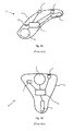
Figure 3 is a schematic perspective representation of a hearing aid module according to a further embodiment of the present invention. - With reference to
Figure 1 , a Behind-the-Ear (BTE)hearing aid 10 according to the prior art normally comprises acasing 2 which accommodates a multiplicity of electric components. According to the terminology commonly employed in the present technical field, acasing 2 for ITEs, CICs and IICs can alternatively be designated as a shell.
Such a multiplicity of electric components generally comprises anenergy storage device 6, such as a battery or accumulator, which is accommodated in a respective compartment.
Moreover, a hearing aid such as the one ofFigure 1 usually comprises a firstelectroacoustic transducer 1, such as a microphone, for converting sound waves into electrical signals.
In addition, thecasing 2 of the hearing device according to the prior art usually comprises a second electroacoustic transducer 1', namely a receiver, for converting electrical signals into sound waves compatible with human hearing and reception thereof by the hearing aid's user.
Asignal processing circuitry 3, typically comprising a processor - in digital hearing aids also called digital signal processor (DSP) - is configured to receive from anelectroacoustic transducer 1, e.g. a microphone, an electrical input signal. The electrical input signal results from the conversion of input sound waves into electrical signals.
Thesignal processing circuitry 3 provides an electroacoustic transducer 1', e.g. a receiver, with an electric output signal. The receiver converts the electrical output signals into sound waves usually transmitted to the user's eardrum. - A conventional Behind-the-Ear (BTE)
hearing aid 10 as portrayed inFigure 1A can also comprise amanual switch 9 allowing the user to manually change some signal processing settings sent to thesignal processing circuitry 3.
Such manual switches are practical and effective only to the extent that the corresponding hearing aids provide enough accessibility to allow engagement by a user's finger or similar with some activation means on the switches, such as a lever or a push button. Completely in the ear (CIC) hearing aids in particular, as well as within the ear (ITE) hearing aids for some designs, are generally positioned in a way that manual switches do not represent a valid solution. Analogous considerations apply, of course, to so-called invisible in the canal (IIC) hearing aids.
Even BTE hearing aids as shown inFigure 1A can additionally comprise non-manually actuated switches, for instance magnetic switches, for adjusting the operational parameters of thesignal processing circuitry 3. -
Figure 1B schematically represents a known within the ear (ITE)hearing aid 10 which, mutatis mutandis, comprises within a casing orshell 2 the same components described in connection with the example ofFigure 1A .
In the case of the hearing device ofFigure 1B , the settings and operational parameters of thesignal processing circuitry 3 are substantially adjusted by a sensor orswitch 4 which is not intended to be manually operated and can be, for instance, a magnetically actuatable switch instructing operational parameter changes from remote, following the detection of a corresponding change of an imparted magnetic field. - It is evident from
Figure 1A and Figure 1B how in the prior art switches for the automatic or semi-automatic adjustment of operational parameters of thesignal processing circuitry 3, such as magnetic actuatable switches 4, are positioned within thecasing 2 in respective housings which are disposed spatially separate with respect to the housings of all other hearing aid components. Specifically, the housing ofswitches 4 is spatially decoupled and separate from that of inputelectroacoustic transducer 1 and/or output electroacoustic transducer 1'. - As above pointed out, the self-standing positioning of
switches 4 in prior art hearing aids is such that corresponding faceplate space is taken up for the mounting thereof. This configuration adversely affects the overall space requirements within thecasing 2; complicates product manufacturing and assembly in that a number of additional components needs to be secured to respective portions of the faceplate or support; and forces to fit in the given volume of a casing a proportionally higher number of wires for separate and dedicated connection of themagnetic sensors 4 to a power supply and to other hearing aid components. - A hearing aid according to the present invention comprises a
casing 2, otherwise designated as shell, accommodating at least an electroacoustic transducer;signal processing circuitry 3 and a magneticallyactuatable switch 4. The electroacoustic transducer can be amicrophone 1; alternatively, it can be a receiver 1'. According to one possible embodiment, the hearing aid according to the present invention can comprise both amicrophone 1 and a receiver 1'. As above explained, an electroacoustic transducer can be also provided with both functionalities of a microphone and a receiver integrated into one component. In the following, it will be understood that a microphone can be any kind of microphone suitable to a hearing aid, such as for instance an electret condenser microphone or a silicon microphone, usually designated as MEMS microphone. - The
signal processing circuitry 3 typically comprises a processor, or DSP, and is configured to receive from the at least oneelectroacoustic transducer 1 an electrical input signal and/or to provide the at least one electroacoustic transducer 1' with an electric output signal.
As already explained, in the present technical context, an electrical input signal typically is the result of a conversion of sound waves picked up by amicrophone 1 into an electrical signal, to be further elaborated by theprocessing circuitry 3; whereas an electrical output signal transmitted from theprocessing circuitry 3 is used by a receiver 1' for conversion into sound waves optimized for the hearing aid's user. - The
magnetically actuatable switch 4 of the hearing aid according to the present invention can be, for example, any of a GMR switch; a TMR switch; an AMR switch; a reed switch or a Hall effect sensor. At any rate, any type of magneto-resistive switch is in principle suitable to implement the magneticallyactuatable switch 4 of the present invention. - Differently from the prior art exemplified in
Figures 1A and 1B , the hearing aid according to the present invention is structured in a way that the magneticallyactuatable switch 4 and theelectroacoustic transducer 1, 1' advantageously form asingle module 50, as it is portrayed inFigure 2 .
Figure 2 represents one preferred embodiment of the present invention wherein the electroacoustic transducer is amicrophone 1. However, as above explained, the at least one electroacoustic transducer can alternatively be a receiver 1', or even an electroacoustic transducer encompassing both the functions of a microphone and a receiver. - The configuration is such that the
single module 50 formed by themagnetically actuatable switch 4 and theelectroacoustic transducer 1, 1' comprises at least oneelectric contact 8', 8" that is advantageously shared between theelectroacoustic transducer 1, 1' and themagnetically actuatable switch 4. - The one
common module 50 as above defined preferably comprises ahousing 5 of theelectroacoustic transducer 1, 1'. In the case exemplified inFigures 2 and 3 relative to two possible embodiments of the present invention, themodule 50 comprises thehousing 5 of themicrophone 1. According to one embodiment of the present invention, the magneticallyactuatable switch 4, such as a GMR sensor, is placed directly onto the printed circuit board of theelectroacoustic transducer 1, 1'. In the case ofFigure 2 , a silicon die of the GMR sensor is placed directly onto the printed circuit board of themicrophone 1.
When the silicon die of the GMR sensor is placed directly onto the printed circuit board of themicrophone 1, preferably such GMR die shares the same printed circuit board as a preamplifier of themicrophone 1.
In case the microphone is a MEMS microphone, the die of the GMR sensor can share the same printed circuit board as the MEMS' die.
The printed circuit board of themicrophone 1 itself is not conductive; this allows to advantageously achieve a gain in the detection power of a sensor such as a GMR sensor.
In the representation ofFigures 2 and 3 , a sound inlet ofmicrophone 1 is indicated byreference number 7. - In order to fully benefit from the combination of spatial coupling between
electroacoustic transducer 1,1' andmagnetic switch 4 according to the present invention, the at least onecontact 8', 8" shared between theelectroacoustic transducer 1, 1' and themagnetically actuatable switch 4 can be advantageously positioned at thehousing 5 of thesingle module 50. The sharedelectric contact 8', 8" can be configured to receive power for theelectroacoustic transducer 1, 1' and for themagnetically actuatable switch 4; or it can be configured to form a common ground contact. - With reference to the embodiments of
Figures 2 and ofFigure 3 , thehousing 5 in thesingle module 50 advantageously comprises an array ofelectric contacts 8', 8", 8m and 8s. Such an array ofelectric contacts 8', 8", 8m and 8s is preferably positioned at a contact area Ca of thehousing 5 of theelectroacoustic transducer 1, 1'.Electric contacts 8', 8", 8m and 8s can be, for example, in the form of solder pads.
In a specific embodiment, the contact area Ca incorporates at least common inputelectric contacts 8', 8" configured to receive power, both for theelectroacoustic transducer 1, 1' and for themagnetically actuatable switch 4, from a power supply means such as abattery 6. By integrating suchcommon contacts 8', 8" in thehousing 5, the overall bulkiness can be advantageously reduced and a higher degree of order among the wiring maintained. - Moreover, the contact area Ca can also advantageously incorporate output electrical contacts for transmission of signals out of the
electroacoustic transducer 1, 1' and out of themagnetic switch 4. With reference to the two embodiments represented inFigures 2 and 3 , one outputelectrical contact 8m is integrated in thehousing 5 at the contact area Ca for outputting signals transmitted by theelectroacoustic transducer 1, 1'; whereas a further outputelectrical contact 8s is integrated in thehousing 5 at the contact area Ca for outputting signals transmitted by themagnetic switch 4. - Preferably, the
module 50 formed by magneticallyactuatable switch 4 and byelectroacoustic transducer 1, 1' is designed in a way that theswitch 4 is secured to a wall of thehousing 5 of theelectroacoustic transducer 1, 1'. - The
switch 4 can be secured to thehousing 5 of theelectroacoustic transducer 1, 1' by any suitable means of fixation or fastening. In a preferred embodiment, theswitch 4 is fixed to a wall of thehousing 5 of theelectroacoustic transducer 1, 1'.
Theswitch 4 can also be made integral with thehousing 5, for instance by fixing it in the surrounding material of thehousing 5, e.g. by embedding it in the housing's walls. Whatever the technique employed for securing theswitch 4 to thehousing 5, the resulting configuration will be such that at least oneelectric contact 8', 8" is shared betweenswitch 4 andelectroacoustic transducer 1, 1'. - In general, the magnetically
actuatable switch 4 can be disposed internal to thehousing 5 of the at least oneelectroacoustic transducer 1, 1'. This is the case of the embodiment exemplified inFigure 2 . InFigure 2 it is schematically represented awire 12 connecting the microphone'selectronics 11 to a shared contact 8' which is preferably configured to receive power for themicrophone 1. InFigure 2 it is further schematically represented awire 13 connecting themagnetic switch 4 to the same, shared contact 8' which is also preferably configured to receive power for themagnetic switch 4. - When the magnetically
actuatable switch 4 is disposed internal to thehousing 5, it is preferable that thehousing 5 of theelectroacoustic transducer 1, 1' is made of a material that is magnetically conductive. Thus, themagnetic switch 4 can easily detect a change in magnetic field and, as a consequence, instruct by transmission of a proportional signal the adjustment of operational parameters of thesignal processing circuitry 3 whenever a threshold magnetic field or the change thereof is detected.
However, it is not an absolute requirement that thehousing 5 be magnetically conductive in case the magneticallyactuatable switch 4 is disposed in the housing. In fact, some of themagnetically actuatable switches 4 nowadays available are so sensitive to magnetic field changes that positioning of such switches inside a magnetically shieldedhousing 5 of anelectroacoustic transducer 1, 1' still guarantees the correct functioning of the magnetic switch. Therefore the overall configuration of a hearing aid according to the present invention is also substantially compatible with an embodiment wherein a magneticallyactuatable switch 4 is positioned in ahousing 5 of theelectroacoustic transducer 1, 1' that is at least partially magnetically shielded.
At any rate, in order to facilitate magnetic field penetration inside thehousing 5, particularly in the case of magneticallynon-conductive housing 5, an opening can also be advantageously provided in thehousing 5.
Thehousing 5 can also advantageously be given a shape that biases the magnetic field in a way that the magnetic field is best detected by themagnetically actuatable switch 4. - Alternatively, the magnetically
actuatable switch 4 can be disposed external to thehousing 5 of theelectroacoustic transducer 1, 1'. This is the case of the embodiment exemplified inFigure 3 . Theswitch 4 can be fixed, for instance, to an external surface of a wall of thehousing 5, in correspondence of the contact area Ca or adjacent thereto, the resulting configuration being anyhow such that at least oneelectric contact 8', 8" is shared betweenswitch 4 andelectroacoustic transducer 1, 1'. The body of theswitch 4 can also be used to provide for a closure of thehousing 5 of theelectroacoustic transducer 1, 1'. - When the magnetically
actuatable switch 4 is disposed external to thehousing 5, preferably at least a magnetically shielding element is interposed between theelectroacoustic transducer 1, 1' and themagnetically actuatable switch 4.
Such a magnetically shielding element advantageously ensures that the change in magnetic field used for activating themagnetic switch 4 does not overly affect the user-friendly functioning of theelectroacoustic transducer 1, 1'.
In this instance, theentire housing 5 can be made of magnetically shielding material.
Alternatively, just the most relevant portion of thehousing 5 at the interface betweenswitch 4 andtransducer 1, 1' can be made of magnetically shielding material. - In one preferred embodiment, the magnetically
actuatable switch 4 is a GMR sensor. The latest models of GMR-sensors available on the market are extremely sensitive to changes of magnetic fields, to the point that GMR-sensors come to perceive even the Earth's magnetic field. Accordingly, the use of a GMR-sensor can limit to a minimum the interferences between magnetic fields applied to the magnetic switches and electroacoustic transducers such asmicrophones 1. If any residual interference withstands, this just gives an indication to the user of the fact that the actuation of themagnetic switch 4 by application of a given magnetic field has actually succeeded, at the most for the short timeframe employed for applying such magnetic field.
Preferably, the magneticallyactuatable switch 4 can be equipped with a magnetic flux intensifier so as to enhance its capacity to detect even weak or very weak magnetic fields. - Thanks to physical disposition of the magnetically actuatable
switch 4 relative to theelectroacoustic transducer 1, 1', the use of the space available within thecasing 2 of thehearing aid 10 according to the present invention is optimized. - The
magnetically actuatable switch 4 and theelectroacoustic transducer 1, 1' each maintain their respective functionality, but the spatial coupling between them allows to save on faceplate space taken up by components, which is crucial in the present technical field. - Also, the special relative positioning of
magnetic switch 4 andelectroacoustic transducer 1, 1' allows to save on number of required electrical connections and, proportionally, on number of wires required to connect the components of thehearing aid 10 between themselves and with a power supply, such as abattery 6.
Claims (7)
- A hearing aid (10) comprising a casing (2) accommodating:▪ an electroacoustic transducer (1, 1'),▪ a signal processing circuitry (3), configured to receive from said electroacoustic transducer (1) an electrical input signal and/or to provide said electroacoustic transducer (1') with an electrical output signal, and▪ a magnetically actuatable switch (4) for adjusting the operational parameters of said signal processing circuitry (3) ;
characterized in that
said magnetically actuatable switch (4) and said electroacoustic transducer (1, 1') form a single module (50) that comprises at least one electric contact (8', 8") that is shared between said electroacoustic transducer (1, 1') and
said magnetically actuatable switch (4). - The hearing aid according to claim 1, wherein said module (50) comprises a housing (5) of said electroacoustic transducer (1, 1') and wherein said shared electric contact (8', 8") is positioned at said housing (5).
- The hearing aid according to claim 2, wherein said shared electric contact (8', 8") is configured to receive power for said electroacoustic transducer (1 ,1') and for said magnetically actuatable switch (4) or forms a common ground contact.
- The hearing aid according to claims 2 to 3, wherein said magnetically actuatable switch (4) is fixed to a wall of the housing (5) of said electroacoustic transducer (1, 1').
- The hearing aid according to claims 2 to 4, wherein said magnetically actuatable switch (4) is disposed internal to the housing (5).
- The hearing aid according to claims 2 to 5, wherein the housing (5) of said electroacoustic transducer (1, 1') comprises at least partially a magnetically shielding material.
- The hearing aid according to claims 1 to 6, wherein said magnetically actuatable switch (20) is a GMR-switch, a TMR-switch, an AMR-switch, a reed switch or a Hall effect sensor.
Priority Applications (1)
| Application Number | Priority Date | Filing Date | Title |
|---|---|---|---|
| EP15171725.3A EP3104626A1 (en) | 2015-06-11 | 2015-06-11 | Hearing aid having a magnetic switch integrated into a microphone |
Applications Claiming Priority (1)
| Application Number | Priority Date | Filing Date | Title |
|---|---|---|---|
| EP15171725.3A EP3104626A1 (en) | 2015-06-11 | 2015-06-11 | Hearing aid having a magnetic switch integrated into a microphone |
Publications (1)
| Publication Number | Publication Date |
|---|---|
| EP3104626A1 true EP3104626A1 (en) | 2016-12-14 |
Family
ID=53385558
Family Applications (1)
| Application Number | Title | Priority Date | Filing Date |
|---|---|---|---|
| EP15171725.3A Withdrawn EP3104626A1 (en) | 2015-06-11 | 2015-06-11 | Hearing aid having a magnetic switch integrated into a microphone |
Country Status (1)
| Country | Link |
|---|---|
| EP (1) | EP3104626A1 (en) |
Citations (6)
| Publication number | Priority date | Publication date | Assignee | Title |
|---|---|---|---|---|
| WO1996007295A1 (en) | 1994-08-31 | 1996-03-07 | Argosy Electronics Inc. | Apparatus and method for magnetically controlling a hearing aid |
| WO2000032009A2 (en) * | 1998-11-25 | 2000-06-02 | Insonus Medical, Inc. | Semi-permanent canal hearing device |
| EP1613125A2 (en) * | 2004-07-02 | 2006-01-04 | Sonion Nederland B.V. | Microphone assembly comprising magnetically activable element for signal switching and field indication |
| US20120087526A1 (en) * | 2010-10-08 | 2012-04-12 | Starkey Laboratories, Inc. | Housing for a standard fit hearing assistance device |
| US20130129128A1 (en) * | 2011-11-23 | 2013-05-23 | Insound Medical, Inc. | Canal hearing devices and batteries for use with same |
| DE202014002530U1 (en) * | 2014-03-24 | 2014-05-15 | Phonak Ag | Hearing aid to be worn in the auditory canal |
-
2015
- 2015-06-11 EP EP15171725.3A patent/EP3104626A1/en not_active Withdrawn
Patent Citations (6)
| Publication number | Priority date | Publication date | Assignee | Title |
|---|---|---|---|---|
| WO1996007295A1 (en) | 1994-08-31 | 1996-03-07 | Argosy Electronics Inc. | Apparatus and method for magnetically controlling a hearing aid |
| WO2000032009A2 (en) * | 1998-11-25 | 2000-06-02 | Insonus Medical, Inc. | Semi-permanent canal hearing device |
| EP1613125A2 (en) * | 2004-07-02 | 2006-01-04 | Sonion Nederland B.V. | Microphone assembly comprising magnetically activable element for signal switching and field indication |
| US20120087526A1 (en) * | 2010-10-08 | 2012-04-12 | Starkey Laboratories, Inc. | Housing for a standard fit hearing assistance device |
| US20130129128A1 (en) * | 2011-11-23 | 2013-05-23 | Insound Medical, Inc. | Canal hearing devices and batteries for use with same |
| DE202014002530U1 (en) * | 2014-03-24 | 2014-05-15 | Phonak Ag | Hearing aid to be worn in the auditory canal |
Similar Documents
| Publication | Publication Date | Title |
|---|---|---|
| US8542858B2 (en) | Hearing device with a space-saving arrangement of microphones and sound openings | |
| US8295517B2 (en) | Hearing apparatus with a common connection for shielding and identification of a receiver | |
| US8867769B2 (en) | Behind-the-ear hearing aid having a plug-in connector | |
| CN109845295B (en) | Hearing aids and hearing aids | |
| US20130308807A1 (en) | Method and apparatus for harvesting energy in a hearing assistance device | |
| US20080226108A1 (en) | Receiver with an additional shielding facility | |
| EP4017024A1 (en) | Support foam for push button in hearing device | |
| CN109756835B (en) | Hearing device | |
| US8605924B2 (en) | Hearing apparatus including transponder detection and corresponding control method | |
| US8630432B2 (en) | Self-programming hearing apparatus and corresponding method | |
| US20150163606A1 (en) | Visual indicators for a hearing aid | |
| US8124900B2 (en) | Pushbutton for a hearing device | |
| US10091593B2 (en) | Hearing device | |
| US20130077808A1 (en) | Ite hearing instrument with programming connector | |
| EP3205120A1 (en) | A hearing device | |
| US8107658B2 (en) | Hearing instrument with parameter resetting and corresponding method | |
| CN113225655B (en) | hearing aid | |
| AU2007240218B2 (en) | Hearing apparatus including transponder detection and corresponding control method | |
| CN101166376B (en) | Hearing aid with conductive metal bow | |
| US8165331B2 (en) | Hearing apparatus with variably mounted control element | |
| US7881487B2 (en) | Hearing aid device with digital control elements | |
| US20250344028A1 (en) | Hearing instrument with antenna and capacitive control unit | |
| CN221995624U (en) | Hearing devices | |
| US8855348B2 (en) | Telecoil in a detachable direct audio input accessory | |
| US20150086053A1 (en) | Hearing instrument with battery compartment switch |
Legal Events
| Date | Code | Title | Description |
|---|---|---|---|
| PUAI | Public reference made under article 153(3) epc to a published international application that has entered the european phase |
Free format text: ORIGINAL CODE: 0009012 |
|
| AK | Designated contracting states |
Kind code of ref document: A1 Designated state(s): AL AT BE BG CH CY CZ DE DK EE ES FI FR GB GR HR HU IE IS IT LI LT LU LV MC MK MT NL NO PL PT RO RS SE SI SK SM TR |
|
| AX | Request for extension of the european patent |
Extension state: BA ME |
|
| STAA | Information on the status of an ep patent application or granted ep patent |
Free format text: STATUS: THE APPLICATION IS DEEMED TO BE WITHDRAWN |
|
| 18D | Application deemed to be withdrawn |
Effective date: 20170615 |