EP3104610A1 - Method and device for encoding color differences for color picture data - Google Patents

Method and device for encoding color differences for color picture data Download PDF

Info

Publication number
EP3104610A1
EP3104610A1 EP15305887.0A EP15305887A EP3104610A1 EP 3104610 A1 EP3104610 A1 EP 3104610A1 EP 15305887 A EP15305887 A EP 15305887A EP 3104610 A1 EP3104610 A1 EP 3104610A1
Authority
EP
European Patent Office
Prior art keywords
component
color
picture data
encoding
color picture
Prior art date
Legal status (The legal status is an assumption and is not a legal conclusion. Google has not performed a legal analysis and makes no representation as to the accuracy of the status listed.)
Withdrawn
Application number
EP15305887.0A
Other languages
German (de)
French (fr)
Inventor
Fabrice Leleannec
Sébastien Lasserre
Patrick Lopez
Yannick Olivier
David Touze
Current Assignee (The listed assignees may be inaccurate. Google has not performed a legal analysis and makes no representation or warranty as to the accuracy of the list.)
Thomson Licensing SAS
Original Assignee
Thomson Licensing SAS
Priority date (The priority date is an assumption and is not a legal conclusion. Google has not performed a legal analysis and makes no representation as to the accuracy of the date listed.)
Filing date
Publication date
Application filed by Thomson Licensing SAS filed Critical Thomson Licensing SAS
Priority to EP15305887.0A priority Critical patent/EP3104610A1/en
Priority to TW105117485A priority patent/TW201711474A/en
Priority to PCT/EP2016/062824 priority patent/WO2016198364A1/en
Priority to CN201680033694.6A priority patent/CN107950027A/en
Priority to KR1020177035227A priority patent/KR20180017018A/en
Priority to JP2017563181A priority patent/JP2018524869A/en
Priority to EP16732462.3A priority patent/EP3308546A1/en
Priority to US15/735,174 priority patent/US10757427B2/en
Publication of EP3104610A1 publication Critical patent/EP3104610A1/en
Withdrawn legal-status Critical Current

Links

Images

Classifications

    • HELECTRICITY
    • H04ELECTRIC COMMUNICATION TECHNIQUE
    • H04NPICTORIAL COMMUNICATION, e.g. TELEVISION
    • H04N19/00Methods or arrangements for coding, decoding, compressing or decompressing digital video signals
    • H04N19/10Methods or arrangements for coding, decoding, compressing or decompressing digital video signals using adaptive coding
    • H04N19/169Methods or arrangements for coding, decoding, compressing or decompressing digital video signals using adaptive coding characterised by the coding unit, i.e. the structural portion or semantic portion of the video signal being the object or the subject of the adaptive coding
    • H04N19/186Methods or arrangements for coding, decoding, compressing or decompressing digital video signals using adaptive coding characterised by the coding unit, i.e. the structural portion or semantic portion of the video signal being the object or the subject of the adaptive coding the unit being a colour or a chrominance component
    • HELECTRICITY
    • H04ELECTRIC COMMUNICATION TECHNIQUE
    • H04NPICTORIAL COMMUNICATION, e.g. TELEVISION
    • H04N19/00Methods or arrangements for coding, decoding, compressing or decompressing digital video signals
    • H04N19/10Methods or arrangements for coding, decoding, compressing or decompressing digital video signals using adaptive coding
    • H04N19/102Methods or arrangements for coding, decoding, compressing or decompressing digital video signals using adaptive coding characterised by the element, parameter or selection affected or controlled by the adaptive coding
    • H04N19/124Quantisation
    • HELECTRICITY
    • H04ELECTRIC COMMUNICATION TECHNIQUE
    • H04NPICTORIAL COMMUNICATION, e.g. TELEVISION
    • H04N19/00Methods or arrangements for coding, decoding, compressing or decompressing digital video signals
    • H04N19/40Methods or arrangements for coding, decoding, compressing or decompressing digital video signals using video transcoding, i.e. partial or full decoding of a coded input stream followed by re-encoding of the decoded output stream
    • HELECTRICITY
    • H04ELECTRIC COMMUNICATION TECHNIQUE
    • H04NPICTORIAL COMMUNICATION, e.g. TELEVISION
    • H04N19/00Methods or arrangements for coding, decoding, compressing or decompressing digital video signals
    • H04N19/44Decoders specially adapted therefor, e.g. video decoders which are asymmetric with respect to the encoder
    • HELECTRICITY
    • H04ELECTRIC COMMUNICATION TECHNIQUE
    • H04NPICTORIAL COMMUNICATION, e.g. TELEVISION
    • H04N19/00Methods or arrangements for coding, decoding, compressing or decompressing digital video signals
    • H04N19/50Methods or arrangements for coding, decoding, compressing or decompressing digital video signals using predictive coding
    • H04N19/593Methods or arrangements for coding, decoding, compressing or decompressing digital video signals using predictive coding involving spatial prediction techniques

Definitions

  • the present disclosure generally relates to encoding color differences for color picture data represented, for example, in the CIEXYZ, CIELab or any color spaces.
  • Encoding color differences for color picture data belonging to an input three dimensional color space (C1, C2, C3) stands for representing the triplets of the color picture data in an output three dimensional color space (D1, D2, D3) where D1 is a first component defined from the component C1, D2 is a first color difference component defined from the component C2 and the component C1, and D3 is a second color difference component defined from the component C3 and the component C1.
  • the CIEXYZ or RGB color spaces are examples of input color space and the CIELab or YDzDx (" WD SMPTE Standard: YDzDx Color-Difference Encoding for XYZ integer signals", version 1.06 of 2014-03-03 ) color spaces are examples of the output color space but the disclosure is not limited to any input and/or output specific color space.
  • encoding color differences comprises color-transforming the triplets of color picture data to triplets of the three dimensional space and quantizing said color-transformed triplets.
  • E A stands for a floating point version of a value A
  • D A stands for an integer (digital) version of a value A.
  • These upper and lower bounds can be determined according to the range of a component of the color picture values in order, for example, to be supported by a coding scheme.
  • Decoding the triplets ( D D 1 , D D 2 , D D 3 ) of color differences which belong to the output color space is the mathematical inverse of the encoding of said color differences as illustrated in Fig. 2 .
  • Modules IQ1, IQ2 and IQ3 are configured to obtain inverse-quantized triplets E D 1 , ⁇ E D 2 ⁇ , E D 3 ⁇ by inverse-quantizing the triplets ( D D 1 , D D 2 , D D 3 ) and a module D1D2D3-to-C1C2C3 is configured to obtain triplets of decoded color picture data C 1 ⁇ C 2 ⁇ C 3 ⁇ by inverse-transforming the inverse-quantized triplets E D 1 , ⁇ E D 2 ⁇ , E D 3 ⁇
  • encoding color differences involves calculating color differences (equations (1), (3) or (5) for example) between the component C2 (respectively C3) and the component C1 but decoding color differences involves calculating sums between the color difference components D D 2 (respectively D D 3 ) and D D 1 as illustrated by equations (8) or (9) for example.
  • Those color difference components D D 2 (respectively D D 3 ) are quantized versions of the color-transformed version of the component C2 (respectively C3) and the sums are thus calculated between quantized components but the color differences are calculated between non-quantized versions of the components. Consequently, encoding/decoding color differences according to the prior art involves cumulating quantizing errors that lead to errors on the triplets ( X ⁇ , ⁇ , ⁇ ) of the decoded color picture data.
  • aspects of the present disclosure are directed to creating and maintaining semantic relationships between data objects on a computer system.
  • the following presents a simplified summary of the disclosure in order to provide a basic understanding of some aspects of the disclosure. This summary is not an extensive overview of the disclosure. It is not intended to identify key or critical elements of the disclosure. The following summary merely presents some aspects of the disclosure in a simplified form as a prelude to the more detailed description provided below.
  • the present disclosure relates to a method for encoding color differences for color picture data comprising three components C1, C2 and C3 of an input color space, said color differences comprising a first component defined from the component C1, a first color difference component defined from the component C2, and a second color difference component defined from the component C3.
  • the method comprises:
  • the process applied to the component C1 comprises a quantizing of the component C1 and the inverse process applied to the first component comprises an inverse-quantizing of the first component.
  • Using a quantized-and-inverse-quantized version of the component C1 rather than the component C1 for computing the color differences avoids cumulative quantizing errors because the quantizing error on the component C1 is taken into account to calculate the color differences.
  • the process applied to the component C1 comprises an encoding of the component C1 and the inverse process applied to the first component comprises a decoding of the first component.
  • the process applied to the component C1 comprises a quantizing of the component C1 followed by an encoding of the quantized component C1 and the inverse process applied to the first component comprises a decoding of the first component followed by an inverse-quantizing of the decoded component.
  • the method further comprises applying a transfer function on the color picture data in order to obtain non-linear color picture data.
  • the method further comprises inverse-quantizing each component of the color picture data before applying the process to the component C1.
  • the input color space is the CIEXYZ color space or the YDzDx color space.
  • the present disclosure relates to a method for encoding color picture data which comprises an encoding color differences for said color picture data according to a method above.
  • the obtaining of a first component by applying a process to the component C1 comprises calculating a residual of the component C1 of color picture data.
  • the residual of the luma component of color picture data is calculated by subtracting a low spatial frequency version of the luma component of the color picture data to said luma component of the color picture.
  • the residual of the luma component of color picture data is calculated by dividing the luma component of the color picture data by a backlight component.
  • the disclosure relates to a computer program product comprising program code instructions to execute the steps of the above method when this program is executed on a computer, a processor readable medium having stored therein instructions for causing a processor to perform at least the steps of the above method, and a non-transitory storage medium carrying instructions of program code for executing steps of the above method when said program is executed on a computing device.
  • each block represents a circuit element, module, or portion of code which comprises one or more executable instructions for implementing the specified logical function(s).
  • the function(s) noted in the blocks may occur out of the order noted. For example, two blocks shown in succession may, in fact, be executed substantially concurrently or the blocks may sometimes be executed in the reverse order, depending on the functionality involved.
  • a picture (sometimes called an image or frame in prior art) contains one or several arrays of samples (pixel values) in a specific picture/video format which specifies all information relative to the pixel values of a picture (or a video) and all information which may be used by a display and/or a decoding device to visualize and/or decode a picture (or video).
  • a picture comprises at least one component, in the shape of a first array of samples, usually a luma (or luminance) component, and, possibly, at least one other component, in the shape of at least one other array of samples, usually a color component.
  • the disclosure is described for encoding/decoding a picture but extends to the encoding/decoding of a sequence of pictures (video) because each picture of the sequence is sequentially encoded/decoded as described below.
  • the method for encoding color differences for color picture data further comprises:
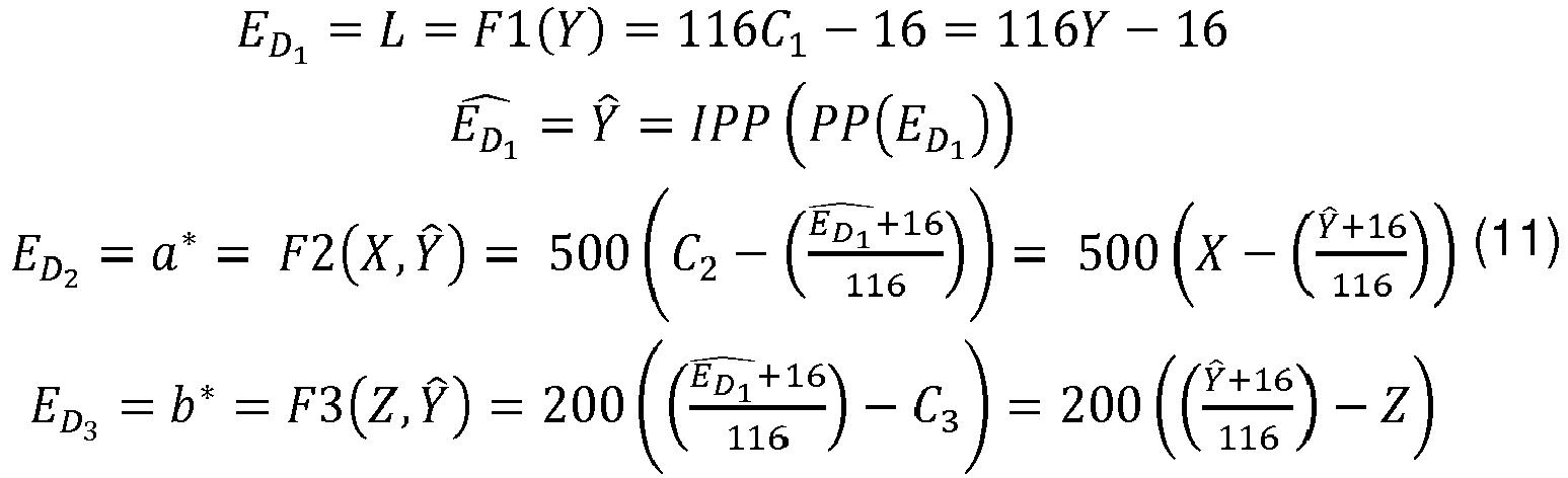
  • Equation (10) shows that the component E D 1 is defined from the component C1 in first, next the second component E D 1 ⁇ is obtained and finally, the color difference components E D 2 and E D 3 are obtained from the components C2 and C3 and the second component E D 1 ⁇ .
  • E D 1 , E D 2 , E D 3 , the triplets ( E D 1 , E D 2 , E D 3 , ) is approximated by the following equations:
  • triplets ( D D 1 , D D 2 , D D 3 ) of integer values of the output color space are then obtained by quantizing the triplets ( E D 1 , E D 2 , E D 3 ) according to equations (2).
  • the process PP applied to the component C1 comprises a quantizing of the component C1 and the inverse process IPP applied to the first component comprises an inverse-quantizing of the first component.
  • this embodiment avoids cumulating the quantizing error on the component C1 for encoding the color differences and then increases the performance of the color difference encoding.
  • the process PP applied to the component C1 comprises an encoding of the component C1 and the inverse process IPP applied to the first component comprises a decoding of the first component.
  • this embodiment avoids cumulating the coding error, introduced by the encoding and decoding operations E/D, of the component C1 for encoding the color differences and then increases the performance of the color difference encoding.
  • the process PP applied to the component C1 comprises an video encoding of a spatial block of the component C1 and the inverse process IPP applied to the first component comprises a video decoding (e.g. HEVC) of said spatial block of the first component.
  • a video decoding e.g. HEVC
  • the encoding operation E may be implemented in an encoder ENC1 adapted to encode a component of color picture data and the decoding operation D may be implemented by a decoder DEC1 adapted to decode a component of color picture data.
  • the process PP applied to the component C1 comprises a quantizing of the component C1 followed by an encoding of the quantized component C1 and the inverse process IPP applied to the first component comprises a decoding of the first component followed by an inverse-quantizing of the decoded component.
  • this embodiment avoids cumulating the coding error and the quantizing error on the component C1 for encoding the color differences and then increases the performance of the color difference encoding.
  • the method further comprises obtaining triplets (X', Y', Z') of color picture data by applying a transfer function tf onto the triplets (X,Y,Z) of the CIEXYZ color space, and color differences are then encoded from the triplets (X', Y', Z') of color picture data according to equations (11) or (12).
  • An exemplary transfer function tf is the inverse Electro-Optical Transfer Function (inverse EOTF noted f EOTF -1 ) described in SMPTE "FCD SMPTE Standard High Dynamic Range Electro-Optical Transfer Function of Mastering Reference Displays , SMPTE ST2084:201X, Version 1.24 --- of 2014-06-18".
  • the transfer function f may be of a different form from the gamma function shown above.
  • Fig. 3b illustrates the decoding of color differences according to this variant.
  • the method further comprises obtaining triplets (X', Y', Z') of color picture data by inverse quantizing the triplets ( D x , D y , D z ) according to equations (13), and color differences are encoded from the triplets (X', Y', Z') according to the equations (11) and (12):
  • (X, Y, Z) are triplets of linear data, i.e. this data is proportional to the amount of light received by a given sensor in each component (X,Y,Z), and (X', Y', Z') are triplets of non-linear data, i.e. data represented after having transformed each linear light component (X,Y,Z) with a non-linear function (perceptual curve). Consequently, when the triplets (X', Y', Z') are considered as input of the method for encoding color differences, the color differences are calculated in a non-linear domain.
  • Encoding color differences for color picture data may be used in combination with any encoding/decoding color picture data.
  • the encoding scheme comprises a module Q1 configured to obtain a first component D D 1 by applying a quantizing to the component E D 1 (process PP) and a module IQ1 configured to apply an inverse-quantizing to the first component D D 1 (process IPP).
  • the encoding scheme comprises modules Q2 and Q3 configured to obtain components D D 2 and D D 3 by applying a quantizing to the components E D 2 and E D 3 .
  • the triplets ( D D 1 , D D 2 , D D 3 ) of integer color picture data are then input of an encoder ENC1 adapted to encode these triplets of color picture data into a bitstream F.
  • the decoding scheme comprises a decoder DEC1 configured to obtain the components D D 1 ⁇ D D 2 ⁇ D D 3 ⁇ of integer color picture data by decoding the bitstream F and, the decoding scheme further comprises modules D1D2D3-to-C1C2C3 and IQ1, IQ2, IQ3 to obtain the triplets C 1 ⁇ C 2 ⁇ C 3 ⁇ of decoded color picture from the triplets ( D D 1 , D D 2 , D D 3 ) as described in relation with Fig. 2 .
  • the input of the encoder ENC1 and the output of the decoder DEC1 are integer point values.
  • the encoding scheme comprises an encoder E configured to obtain a first component by encoding the component E D 1 (process PP) and a decoder D configured to decode the first component (process IPP).
  • the encoding scheme comprises an encoder ENC2 adapted to encode the triplets ( E D 1 , E D 2 , E D 3 ) of floating point color picture data into a bitstream F.
  • E D 2 , E D 3 are processed by the encoder ENC2, since E D 1 has already been encoded.
  • the encoding scheme comprises means for calculating a residual, called component E D 1 , of the component C1 of color picture data.
  • such a residual may be calculated by subtracting a low spatial frequency version of the luma component of the color picture data to said luma component of the color picture data.
  • Such a residual may also be calculated by dividing the luma component of the color picture data by a backlight component.
  • the decoding scheme comprises a decoder DEC2 configured to obtain the triplets E D 1 ⁇ E D 2 ⁇ E D 3 ⁇ of decoded color picture, and the decoding scheme further comprises modules D1D2D3-to-C1C2C3 to obtain the triplets C 1 ⁇ C 2 ⁇ C 3 ⁇ of decoded color picture from the triplets E D 1 ⁇ E D 2 ⁇ E D 3 ⁇ as described in relation with Fig. 2 .
  • the input of the encoder ENC2 and the output of the decoder DEC2 are floating point values.
  • the encoding scheme comprises a module Q1 configured to obtain an intermediate component by applying a quantizing to the component E D 1 and an encoder E configured to obtain a first component by encoding said intermediate component (process PP).
  • the encoding scheme further comprises a decoder D configured to decode the first component and a module IQ1 configured to apply an inverse-quantizing to the first decoded component (process IPP).
  • the encoding scheme comprises modules Q2 and Q3 configured to obtain components D D 2 and D D 3 by applying a quantizing to the components E D 2 and E D 3 .
  • the triplets ( D D 1 , D D 2 , D D 3 ) of integer color picture data are then input of an encoder ENC1 adapted to encode these triplets of color picture data into a bitstream F.
  • the decoding scheme is the same as described in Fig. 4b .
  • the decoder D (respectively DEC1, DEC2) is configured to decode data which have been encoded by the encoder D (respectively ENC1, ENC2).
  • the encoder E and/or ENC1 and/or ENC2 (and decoder D and/or DEC1 and/or DEC2) may be block-based processing.
  • the encoders E and/or ENC1 and/or ENC2 (and decoder E and/or DEC1 and/or DEC2) is not limited to a specific encoder (decoder).
  • the encoder E and/or ENC1 and/or ENC2 (and decoder D and/or DEC1 and/or DEC2) is not limited to a specific encoder which may be, for example, an image/video coder with loss like JPEG, JPEG2000, MPEG2, HEVC recommendation ( "High Efficiency Video Coding", SERIES H: AUDIOVISUAL AND MULTIMEDIA SYSTEMS, Recommendation ITU-T H.265, Telecommunication Standardization Sector of ITU, April 2013) or H264/AVC recommendation ("Advanced video coding for generic audiovisual Services", SERIES H: AUDIOVISUAL AND MULTIMEDIA SYSTEMS, Recommendation ITU-T H.264, Telecommunication Standardization Sector of ITU, February 2014)).
  • the modules are functional units, which may or not be in relation with distinguishable physical units. For example, these modules or some of them may be brought together in a unique component or circuit, or contribute to functionalities of a software. A contrario, some modules may potentially be composed of separate physical entities.
  • the apparatus which are compatible with the invention are implemented using either pure hardware, for example using dedicated hardware such ASIC or FPGA or VLSI, respectively «Application Specific Integrated Circuit » « Field-Programmable Gate Array » « Very Large Scale Integration » or from several integrated electronic components embedded in a device or from a blend of hardware and software components.
  • Fig. 5 represents an exemplary architecture of a device 50 which may be configured to implement a method described in relation with Fig. 3-4e .
  • Device 50 comprises following elements that are linked together by a data and address bus 51:
  • the battery 56 is external to the device.
  • the word « register » used in the specification can correspond to area of small capacity (some bits) or to very large area (e.g. a whole program or large amount of received or decoded data).
  • ROM 53 comprises at least a program and parameters. Algorithm of the methods according to the invention is stored in the ROM 53. When switched on, the CPU 52 uploads the program in the RAM and executes the corresponding instructions.
  • RAM 54 comprises, in a register, the program executed by the CPU 52 and uploaded after switch on of the device 50, input data in a register, intermediate data in different states of the method in a register, and other variables used for the execution of the method in a register.
  • the implementations described herein may be implemented in, for example, a method or a process, an apparatus, a software program, a data stream, or a signal. Even if only discussed in the context of a single form of implementation (for example, discussed only as a method or a device), the implementation of features discussed may also be implemented in other forms (for example a program).
  • An apparatus may be implemented in, for example, appropriate hardware, software, and firmware.
  • the methods may be implemented in, for example, an apparatus such as, for example, a processor, which refers to processing devices in general, including, for example, a computer, a microprocessor, an integrated circuit, or a programmable logic device. Processors also include communication devices, such as, for example, computers, cell phones, portable/personal digital assistants ("PDAs”), and other devices that facilitate communication of information between end-users.
  • PDAs portable/personal digital assistants
  • the triplets (C1, C2, C3) or (X, Y, Z) or (D x , D y , D z ) of color picture data are obtained from a source.
  • the source belongs to a set comprising:
  • the output triplets ( X ⁇ , ⁇ , ⁇ ) or C 1 ⁇ C 2 ⁇ C 3 ⁇ of color picture data are sent to a destination; specifically, the destination belongs to a set comprising:
  • the bitstream F is sent to a destination.
  • the bitstream F is stored in a local or remote memory, e.g. a video memory (54) or a RAM (54), a hard disk (53).
  • the bitstream is sent to a storage interface (55), e.g. an interface with a mass storage, a flash memory, ROM, an optical disc or a magnetic support and/or transmitted over a communication interface (55), e.g. an interface to a point to point link, a communication bus, a point to multipoint link or a broadcast network.
  • a storage interface e.g. an interface with a mass storage, a flash memory, ROM, an optical disc or a magnetic support
  • a communication interface e.g. an interface to a point to point link, a communication bus, a point to multipoint link or a broadcast network.
  • the bitstream F is obtained from a source.
  • the bitstream is read from a local memory, e.g. a video memory (54), a RAM (54), a ROM (53), a flash memory (53) or a hard disk (53).
  • the bitstream is received from a storage interface (55), e.g. an interface with a mass storage, a RAM, a ROM, a flash memory, an optical disc or a magnetic support and/or received from a communication interface (55), e.g. an interface to a point to point link, a bus, a point to multipoint link or a broadcast network.
  • device 50 being configured to implement an method described in relation with Fig. 3, 3a, 3c , 4a, 4c or 4e , belongs to a set comprising:
  • device 50 being configured to implement a decoding method described in relation with Fig. 2, 3b , 4b or 4d , belongs to a set comprising:
  • the device A comprises means which are configured to implement a method as described in relation with the Fig. 3, 3a, 3c , 4a, 4c or 4e and the device B comprises means which are configured to implement a method for decoding as described in relation with Fig. 2, 3b , 4b or 4d .
  • the network is a broadcast network, adapted to broadcast still pictures or video pictures from device A to decoding devices including the device B.
  • Implementations of the various processes and features described herein may be embodied in a variety of different equipment or applications, particularly, for example, equipment or applications.
  • equipment examples include an encoder, a decoder, a post-processor processing output from a decoder, a pre-processor providing input to an encoder, a video coder, a video decoder, a video codec, a web server, a set-top box, a laptop, a personal computer, a cell phone, a PDA, and other communication devices.
  • the equipment may be mobile and even installed in a mobile vehicle.
  • a computer readable storage medium can take the form of a computer readable program product embodied in one or more computer readable medium(s) and having computer readable program code embodied thereon that is executable by a computer.
  • a computer readable storage medium as used herein is considered a non-transitory storage medium given the inherent capability to store the information therein as well as the inherent capability to provide retrieval of the information therefrom.
  • a computer readable storage medium can be, for example, but is not limited to, an electronic, magnetic, optical, electromagnetic, infrared, or semiconductor system, apparatus, or device, or any suitable combination of the foregoing. It is to be appreciated that the following, while providing more specific examples of computer readable storage mediums to which the present principles can be applied, is merely an illustrative and not exhaustive listing as is readily appreciated by one of ordinary skill in the art: a portable computer diskette; a hard disk; a read-only memory (ROM); an erasable programmable read-only memory (EPROM or Flash memory); a portable compact disc read-only memory (CD-ROM); an optical storage device; a magnetic storage device; or any suitable combination of the foregoing.
  • the instructions may form an application program tangibly embodied on a processor-readable medium.
  • Instructions may be, for example, in hardware, firmware, software, or a combination. Instructions may be found in, for example, an operating system, a separate application, or a combination of the two.
  • a processor may be characterized, therefore, as, for example, both a device configured to carry out a process and a device that includes a processor-readable medium (such as a storage device) having instructions for carrying out a process. Further, a processor-readable medium may store, in addition to or in lieu of instructions, data values produced by an implementation.
  • implementations may produce a variety of signals formatted to carry information that may be, for example, stored or transmitted.
  • the information may include, for example, instructions for performing a method, or data produced by one of the described implementations.
  • a signal may be formatted to carry as data the rules for writing or reading the syntax of a described embodiment, or to carry as data the actual syntax-values written by a described embodiment.
  • Such a signal may be formatted, for example, as an electromagnetic wave (for example, using a radio frequency portion of spectrum) or as a baseband signal.
  • the formatting may include, for example, encoding a data stream and modulating a carrier with the encoded data stream.
  • the information that the signal carries may be, for example, analog or digital information.
  • the signal may be transmitted over a variety of different wired or wireless links, as is known.
  • the signal may be stored on a processor-readable medium.

Landscapes

  • Engineering & Computer Science (AREA)
  • Multimedia (AREA)
  • Signal Processing (AREA)
  • Compression Or Coding Systems Of Tv Signals (AREA)
  • Processing Of Color Television Signals (AREA)

Abstract

The present disclosure generally relates to a method and device for encoding color differences for color picture data comprising three components C1, C2 and C3 of an input color space, said color differences comprising a first component defined from the component C1, a first color difference component defined from the component C2, and a second color difference component defined from the component C3. The method is characterized in that it further comprises:
- obtaining a first component by applying a process to the component C1;
- obtaining a second component by applying the inverse process to the first component; and
- the first and second color difference components are further defined from the second component.

Description

    2. Field.
  • The present disclosure generally relates to encoding color differences for color picture data represented, for example, in the CIEXYZ, CIELab or any color spaces.
  • 3. Background.
  • The present section is intended to introduce the reader to various aspects of art, which may be related to various aspects of the present disclosure that are described and/or claimed below. This discussion is believed to be helpful in providing the reader with background information to facilitate a better understanding of the various aspects of the present invention. Accordingly, it should be understood that these statements are to be read in this light, and not as admissions of prior art.
  • Encoding color differences for color picture data belonging to an input three dimensional color space (C1, C2, C3) stands for representing the triplets of the color picture data in an output three dimensional color space (D1, D2, D3) where D1 is a first component defined from the component C1, D2 is a first color difference component defined from the component C2 and the component C1, and D3 is a second color difference component defined from the component C3 and the component C1.
  • The CIEXYZ or RGB color spaces are examples of input color space and the CIELab or YDzDx ("WD SMPTE Standard: YDzDx Color-Difference Encoding for XYZ integer signals", version 1.06 of 2014-03-03 ) color spaces are examples of the output color space but the disclosure is not limited to any input and/or output specific color space.
  • According to prior art, encoding color differences comprises color-transforming the triplets of color picture data to triplets of the three dimensional space and quantizing said color-transformed triplets.
  • More precisely, as illustrated in Fig. 1 , a module C1C2C3-to-D1D2D3 is configured to obtain triplets (E D 1 , E D 2 , E D 3 ) of floating point values by color-transforming the triplets (C1, C2, C3) of the input color space according to equations (1): E D 1 = F 1 C 1 E D 2 = F 2 C 2 C 1 E D 3 = F 3 C 3 C 1
    Figure imgb0001

    where F1(), F2() and F3() represent color-transform functions implemented by the module C1 C2C3-to-D1 D2D3.
  • Next, modules Q1, Q2 and Q3 are configured to obtain the triplets (D D 1 , D D 2 , D D 3 ) of integer values of the output color space by quantizing the triplets (E D 1 , E D 2 E D 3 ) according to equations (2): D D 1 = Q 1 E D 1 D D 2 = Q 2 E D 2 D D 3 = Q 3 E D 3
    Figure imgb0002

    where Q1(), Q2() and Q3() represents the quantizing functions implemented by the modules Q1, Q2 and Q3 respectively.
  • Note in the following, the notation EA stands for a floating point version of a value A and DA stands for an integer (digital) version of a value A.
  • According to an example, when the input color space is the CIEXYZ color space (C1=Y, C2=X and C3=Z) and the output color space is the CIELab1976 color space (D1=L, D2=a*, D3=b*), the triplets (X,Y,Z) are color-transformed according to equations (3): E D 1 = L = F 1 Y = 116 Y - 16 E D 2 = a * = F 2 X Y = 500 X - Y E D 3 = b * = F 3 Z Y = 200 Y - Z
    Figure imgb0003
  • The triplets (E D 1 , E D 2 , E D 3 ) given by equation (3) are then quantized according to equations (4): D D 1 = Q 1 E D 1 = INT 876. E D 1 - E D 1 min E D 1 peak - E D 1 min + 64 .2 n - 10 D D 2 = Q 2 E D 2 = INT 896. E D 2 E D 2 peak - E D 2 min + 512 .2 n - 10 D D 3 = Q 3 E D 3 = INT 896. E D 3 E D 3 peak - E D 3 min + 512 .2 n - 10
    Figure imgb0004

    where EDipeak and EDimin (i=1, 2, 3) respectively stand for a predefined peak (bound) and a minimum for a color component ED i.
  • These upper and lower bounds can be determined according to the range of a component of the color picture values in order, for example, to be supported by a coding scheme.
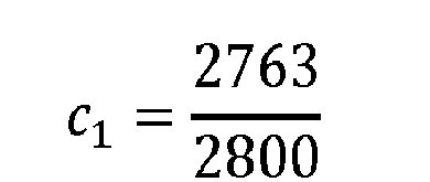
  • According to another example, when the input color space is the CIEXYZ color space (C1=Y, C2=X and C3=Z) and the output color space is the YDzDx color space, the triplets (X, Y, Z) are color-transformed according to equations (5): E D 1 = F 1 Y E D 2 = F 2 X Y = = X - c 2 Y 2.0 E D 3 = F 3 Z Y = c 1 Z - Y 2.0 c 1 = 2763 2800 c 2 = 2741 2763
    Figure imgb0005
  • The triplets (E D 1 , E D 2 , E D 3 ) given by equations (5) are then quantized according to equations (6): D D 1 = Q 1 E D 1 = INT 876. E D 1 + 64 .2 n - 10 D D 2 = Q 2 E D 2 = INT 896. E D 2 + 512 .2 n - 10 D D 3 = Q 3 E D 3 = INT 896. E D 3 + 512 .2 n - 10
    Figure imgb0006
  • Decoding the triplets (D D 1 , D D 2 , D D 3 ) of color differences which belong to the output color space (obtained as explained above in relation with Fig. 1 ) is the mathematical inverse of the encoding of said color differences as illustrated in Fig. 2 .
  • Modules IQ1, IQ2 and IQ3 are configured to obtain inverse-quantized triplets E D 1 , ^ E D 2 ^ , E D 3 ^
    Figure imgb0007
    by inverse-quantizing the triplets (D D 1 , D D 2 , D D 3 ) and a module D1D2D3-to-C1C2C3 is configured to obtain triplets of decoded color picture data C 1 ^ C 2 ^ C 3 ^
    Figure imgb0008
    by inverse-transforming the inverse-quantized triplets E D 1 , ^ E D 2 ^ , E D 3 ^
    Figure imgb0009
  • Equations (7) define the combination of the inverse-quantizing and inverse-transforming operations: C 1 ^ = IF 1 IQ 1 D D 1 C 2 ^ = IF 2 IQ 2 D D 2 , IQ 1 D D 1 C 3 ^ = IF 3 IQ 3 D D 3 , IQ 1 D D 1
    Figure imgb0010

    where IF1(), respectively IF2() and IF3(), represents the inverse of the color-transform function F1(), respectively F2() and F3() implemented by the module C1C2C3-to-D1D2D3 and IQ1(), respectively IQ2() and IQ3(), represents the inverse of the quantizing functions Q1(), respectively Q2() and Q3().
  • According to an example, when the input color space is the CIEXYZ color space (C1=Y, C2=X and C3=Z) and the output color space is the CIELab1976 color space (D1=L, D2=a*, D3=b*), the triplets ( C 2 ^ = X ^ , C 1 ^ =
    Figure imgb0011
    Y ^ , C 3 ^ = Z ^ )
    Figure imgb0012
    ) of decoded color picture data are obtained according to equations (8): E ^ D 1 = IQ 1 D D 1 = 1 876 D D 1 2 n - 10 - 64 E D 1 peak - E D 1 min + E D 1 min E ^ D 2 = IQ 2 D D 2 = 1 448 D D 2 2 n - 10 - 512 E D 2 peak - E D 2 min + E D 2 min E ^ D 3 = IQ 3 D D 3 = 1 448 D D 3 2 n - 10 - 512 E D 3 peak - E D 3 min + E D 3 min C 1 ^ = IF 1 IQ 1 D D 1 = E ^ D 1 + 16 116 C 2 ^ = IF 2 IQ 2 D D 2 , IQ 1 D D 1 = E ^ D 2 500 + E ^ D 1 + 16 116 C 3 ^ = IF 3 IQ 3 D D 3 , IQ 1 D D 1 = E ^ D 1 + 16 116 - E ^ D 3 200
    Figure imgb0013
  • According to another example, when the input color space is the CIEXYZ color space (C1=Y, C2=X and C3=Z) and the output color space is the YDzDx color space, the triplets C 2 ^ = X ^ , C 1 ^ = Y ^ , C 3 ^ = Z ^
    Figure imgb0014
    of decoded color picture data are obtained according to equations (9): X ^ = 2 876 D D 2 2 n - 10 - 512 + d 1 876 D D 1 2 n - 10 - 64 Y ^ = 1 876 D D 1 2 n - 10 - 64 Z ^ = d 2 2 876 D D 3 2 n - 10 - 512 + 1 876 D D 1 2 n - 10 - 64
    Figure imgb0015

    where d1=2741/2763 and d2=2800/2763.
  • According to the prior art, encoding color differences involves calculating color differences (equations (1), (3) or (5) for example) between the component C2 (respectively C3) and the component C1 but decoding color differences involves calculating sums between the color difference components D D 2 (respectively D D 3 ) and D D 1 as illustrated by equations (8) or (9) for example. Those color difference components D D 2 (respectively D D 3 ) are quantized versions of the color-transformed version of the component C2 (respectively C3) and the sums are thus calculated between quantized components but the color differences are calculated between non-quantized versions of the components. Consequently, encoding/decoding color differences according to the prior art involves cumulating quantizing errors that lead to errors on the triplets (X̂,Ŷ,Ẑ) of the decoded color picture data.
  • 4. Summary.
  • In light of the foregoing, aspects of the present disclosure are directed to creating and maintaining semantic relationships between data objects on a computer system. The following presents a simplified summary of the disclosure in order to provide a basic understanding of some aspects of the disclosure. This summary is not an extensive overview of the disclosure. It is not intended to identify key or critical elements of the disclosure. The following summary merely presents some aspects of the disclosure in a simplified form as a prelude to the more detailed description provided below.
  • According to one of its aspects, the present disclosure relates to a method for encoding color differences for color picture data comprising three components C1, C2 and C3 of an input color space, said color differences comprising a first component defined from the component C1, a first color difference component defined from the component C2, and a second color difference component defined from the component C3. The method comprises:
    • obtaining a first component by applying a process to the component C1;
    • obtaining a second component by applying the inverse process to the first component; and
    • the first and second color difference components are further defined from the second component.
  • According to an embodiment, the process applied to the component C1 comprises a quantizing of the component C1 and the inverse process applied to the first component comprises an inverse-quantizing of the first component.
  • Using a quantized-and-inverse-quantized version of the component C1 rather than the component C1 for computing the color differences avoids cumulative quantizing errors because the quantizing error on the component C1 is taken into account to calculate the color differences.
  • According to an embodiment, the process applied to the component C1 comprises an encoding of the component C1 and the inverse process applied to the first component comprises a decoding of the first component.
  • According to an embodiment, the process applied to the component C1 comprises a quantizing of the component C1 followed by an encoding of the quantized component C1 and the inverse process applied to the first component comprises a decoding of the first component followed by an inverse-quantizing of the decoded component.
  • According to an embodiment, the method further comprises applying a transfer function on the color picture data in order to obtain non-linear color picture data.
  • According to an embodiment, the method further comprises inverse-quantizing each component of the color picture data before applying the process to the component C1.
  • According to an embodiment, the input color space is the CIEXYZ color space or the YDzDx color space.
  • According to another of its aspects, the present disclosure relates to a method for encoding color picture data which comprises an encoding color differences for said color picture data according to a method above.
  • According to an embodiment, the obtaining of a first component by applying a process to the component C1 comprises calculating a residual of the component C1 of color picture data.
  • According to an embodiment, when the component C1 is the luma component of the color picture color data, the residual of the luma component of color picture data is calculated by subtracting a low spatial frequency version of the luma component of the color picture data to said luma component of the color picture.
  • According to an embodiment, when the component C1 is the luma component of the color picture color data, the residual of the luma component of color picture data is calculated by dividing the luma component of the color picture data by a backlight component.
  • According to other of its aspects, the disclosure relates to a computer program product comprising program code instructions to execute the steps of the above method when this program is executed on a computer, a processor readable medium having stored therein instructions for causing a processor to perform at least the steps of the above method, and a non-transitory storage medium carrying instructions of program code for executing steps of the above method when said program is executed on a computing device.
  • The specific nature of the disclosure as well as other objects, advantages, features and uses of the disclosure will become evident from the following description of embodiments taken in conjunction with the accompanying drawings.
  • 4. Brief Description of Drawings.
  • In the drawings, an embodiment of the present invention is illustrated. It shows:
    • Fig. 1 shows a block diagram of the steps of a method for encoding color differences for color picture data in accordance with prior art;
    • Fig. 2 shows a block diagram of the steps of a method for decoding color differences in accordance with prior art;
    • Fig. 3 shows a block diagram of the steps of a method for encoding color differences for color picture data in accordance with an example of the present principles;
    • Fig. 3a shows a block diagram of the steps of a method for encoding color differences for color picture data in accordance with an example of the present principles;
    • Fig. 3b shows a block diagram of the steps of a method for decoding color differences for color picture data in accordance with an example of the present principles;
    • Fig. 3c shows a block diagram of the steps of a method for encoding color differences for color picture data in accordance with a variant of the examples of the present principles described in relation with Figs. 3, 3a or 3b .
    • Fig. 4a shows a block diagram of the steps of a method for encoding color picture data in accordance with an example of the present principles;
    • Fig. 4b shows a block diagram of the steps of a method for decoding picture data in accordance with an example of the present principles;
    • Fig. 4c shows a block diagram of the steps of a method for encoding color picture data in accordance with an example of the present principles;
    • Fig. 4d shows a block diagram of the steps of a method for decoding picture data in accordance with an example of the present principles;
    • Fig. 4e shows a block diagram of the steps of a method for encoding color picture data in accordance with an example of the present principles;
    • Fig. 5 shows an example of an architecture of a device in accordance with an example of present principles; and
    • Fig. 6 shows two remote devices communicating over a communication network in accordance with a example of present principles;
  • Similar or same elements are referenced with the same reference numbers.
  • 5. Description of Embodiments.
  • The present disclosure will be described more fully hereinafter with reference to the accompanying figures, in which embodiments of the disclosure are shown. This disclosure may, however, be embodied in many alternate forms and should not be construed as limited to the embodiments set forth herein. Accordingly, while the disclosure is susceptible to various modifications and alternative forms, specific embodiments thereof are shown by way of example in the drawings and will herein be described in detail. It should be understood, however, that there is no intent to limit the disclosure to the particular forms disclosed, but on the contrary, the disclosure is to cover all modifications, equivalents, and alternatives falling within the spirit and scope of the disclosure as defined by the claims.
  • The terminology used herein is for the purpose of describing particular embodiments only and is not intended to be limiting of the disclosure. As used herein, the singular forms "a", "an" and "the" are intended to include the plural forms as well, unless the context clearly indicates otherwise. It will be further understood that the terms "comprises", "comprising," "includes" and/or "including" when used in this specification, specify the presence of stated features, integers, steps, operations, elements, and/or components but do not preclude the presence or addition of one or more other features, integers, steps, operations, elements, components, and/or groups thereof. Moreover, when an element is referred to as being "responsive" or "connected" to another element, it can be directly responsive or connected to the other element, or intervening elements may be present. In contrast, when an element is referred to as being "directly responsive" or "directly connected" to other element, there are no intervening elements present. As used herein the term "and/or" includes any and all combinations of one or more of the associated listed items and may be abbreviated as"/".
  • It will be understood that, although the terms first, second, etc. may be used herein to describe various elements, these elements should not be limited by these terms. These terms are only used to distinguish one element from another. For example, a first element could be termed a second element, and, similarly, a second element could be termed a first element without departing from the teachings of the disclosure.
  • Although some of the diagrams include arrows on communication paths to show a primary direction of communication, it is to be understood that communication may occur in the opposite direction to the depicted arrows.
  • Some embodiments are described with regard to block diagrams and operational flowcharts in which each block represents a circuit element, module, or portion of code which comprises one or more executable instructions for implementing the specified logical function(s). It should also be noted that in other implementations, the function(s) noted in the blocks may occur out of the order noted. For example, two blocks shown in succession may, in fact, be executed substantially concurrently or the blocks may sometimes be executed in the reverse order, depending on the functionality involved.
  • Reference herein to "one embodiment" or "an embodiment" means that a particular feature, structure, or characteristic described in connection with the embodiment can be included in at least one implementation of the disclosure. The appearances of the phrase "in one embodiment" or "according to an embodiment" in various places in the specification are not necessarily all referring to the same embodiment, nor are separate or alternative embodiments necessarily mutually exclusive of other embodiments.
  • Reference numerals appearing in the claims are by way of illustration only and shall have no limiting effect on the scope of the claims.
  • While not explicitly described, the present embodiments and variants may be employed in any combination or sub-combination.
  • In the following, a picture (sometimes called an image or frame in prior art) contains one or several arrays of samples (pixel values) in a specific picture/video format which specifies all information relative to the pixel values of a picture (or a video) and all information which may be used by a display and/or a decoding device to visualize and/or decode a picture (or video). A picture comprises at least one component, in the shape of a first array of samples, usually a luma (or luminance) component, and, possibly, at least one other component, in the shape of at least one other array of samples, usually a color component.
  • The disclosure is described for encoding/decoding a picture but extends to the encoding/decoding of a sequence of pictures (video) because each picture of the sequence is sequentially encoded/decoded as described below.
  • According to the principle of the disclosure, the method for encoding color differences for color picture data, as described in the introducing part in relation with Fig. 1 , further comprises:
    • obtaining a first component by applying a process to the component C1;
    • obtaining a second component E D 1 ^
      Figure imgb0016
      by applying the inverse process to the first component; and
    • the first and second color difference components are further defined from the second component.
  • More precisely, a module PP is configured to obtain a first component by applying a process pro to the component E D 1 and a module IPP is configured to obtain a second component E D 1 ^
    Figure imgb0017
    by applying the inverse process IPP (inverse of the process PP) to said first component as follows: E D 1 ^ = IPP PP E D 1
    Figure imgb0018
  • The module C1C2C3-to-D1D2D3 is then configured to obtain triplets (E D 1 , E D 2 , E D 3 ) by color-transforming the triplets (C1, C2, C3) of the input color space (C1, C2, C3) according to equations (10): E D 1 = F 1 C 1 E D 2 = F 2 C 2 E D 1 ^ E D 3 = F 3 C 3 E D 1 ^
    Figure imgb0019
  • Equation (10) shows that the component E D 1 is defined from the component C1 in first, next the second component E D 1 ^
    Figure imgb0020
    is obtained and finally, the color difference components E D 2 and E D 3 are obtained from the components C2 and C3 and the second component E D 1 ^ .
    Figure imgb0021
  • According to an example, when the input color space is the CIEXYZ color space (C1=Y, C2=X and C3=Z) and the output color space is the CIELab1976 color space (D1=L, D2=a*, D3=b*), the triplets (X, Y, Z) are color-transformed according to equations (11): E D 1 = L = F 1 Y = 116 C 1 - 16 = 116 Y - 16 E D 1 ^ = Y ^ = IPP PP E D 1 E D 2 = a * = F 2 X Y = 500 C 2 - E D 1 ^ + 16 116 = 500 X - Y ^ + 16 116 E D 3 = b * = F 3 Z Y ^ = 200 E D 1 ^ + 16 116 - C 3 = 200 Y ^ + 16 116 - Z
    Figure imgb0022

    where D 1 peak and D 1min respectively stand for a predefined peak (bound) and a minimum for the color component.
  • According to a variant, the triplets (E D 1 ,E D 2, E D 3 ,) is approximated by the following equations: E D 2 = a * = F 2 X Y ^ = 500 X - Y ^ + 16 / 116 E D 3 = b * = F 3 Z Y ^ = 200 Y ^ + 16 / 116 - Z
    Figure imgb0023
  • According to another example, when the input color space is the CIEXYZ color space (C1=Y, C2=X and C3=Z) and the output color space is the YDzDx color space, the triplets (X, Y, Z) are color-transformed according to the following equations: E D 1 = F 1 Y
    Figure imgb0024
    E D 1 ^ = Y ^ = IPP PP E D 1
    Figure imgb0025
    E D 2 = F 2 X Y = = X - c 2 Y ^ 2.0
    Figure imgb0026
    E D 3 = F 3 Z Y = c 1 Z - Y ^ 2.0
    Figure imgb0027
    c 1 = 2763 2800
    Figure imgb0028
    c 2 = 2741 2763
    Figure imgb0029
  • Possibly, triplets (D D 1 , D D 2 , D D 3 ) of integer values of the output color space are then obtained by quantizing the triplets (E D 1 , E D 2 , ED3 ) according to equations (2).
  • The triplets (D D 1 , D D 2 , D D 3 ) of color differences are decoded according to equation (7).
  • According to an embodiment, the process PP applied to the component C1 comprises a quantizing of the component C1 and the inverse process IPP applied to the first component comprises an inverse-quantizing of the first component.
  • Advantageously, this embodiment avoids cumulating the quantizing error on the component C1 for encoding the color differences and then increases the performance of the color difference encoding.
  • According to an embodiment, the process PP applied to the component C1 comprises an encoding of the component C1 and the inverse process IPP applied to the first component comprises a decoding of the first component.
  • Advantageously, this embodiment avoids cumulating the coding error, introduced by the encoding and decoding operations E/D, of the component C1 for encoding the color differences and then increases the performance of the color difference encoding.
  • According to an embodiment, the process PP applied to the component C1 comprises an video encoding of a spatial block of the component C1 and the inverse process IPP applied to the first component comprises a video decoding (e.g. HEVC) of said spatial block of the first component.
  • The encoding operation E may be implemented in an encoder ENC1 adapted to encode a component of color picture data and the decoding operation D may be implemented by a decoder DEC1 adapted to decode a component of color picture data.
  • According to an embodiment, the process PP applied to the component C1 comprises a quantizing of the component C1 followed by an encoding of the quantized component C1 and the inverse process IPP applied to the first component comprises a decoding of the first component followed by an inverse-quantizing of the decoded component.
  • Advantageously, this embodiment avoids cumulating the coding error and the quantizing error on the component C1 for encoding the color differences and then increases the performance of the color difference encoding.
  • According to a variant, illustrated in Fig. 3a , when the input color space is the CIEXYZ color space (C1=Y, C2=X and C3=Z), the method further comprises obtaining triplets (X', Y', Z') of color picture data by applying a transfer function tf onto the triplets (X,Y,Z) of the CIEXYZ color space, and color differences are then encoded from the triplets (X', Y', Z') of color picture data according to equations (11) or (12).
  • An exemplary transfer function tf is the inverse Electro-Optical Transfer Function (inverse EOTF noted fEOTF -1) described in SMPTE "FCD SMPTE Standard High Dynamic Range Electro-Optical Transfer Function of Mastering Reference Displays , SMPTE ST2084:201X, Version 1.24 --- of 2014-06-18". It is given by the following equations; = f EOTF - 1 X = c 1 + c 2 X m 1 1 + c 3 X m 1 m 2
    Figure imgb0030
    = f EOTF - 1 X = c 1 + c 2 Y m 1 1 + c 3 Y m 1 m 2
    Figure imgb0031
    = f EOTF - 1 X = c 1 + c 2 Z m 1 1 + c 3 Z m 1 m 2
    Figure imgb0032

    where
    m1 is the number 2610 / 4096 × 1 4 = 0.1593017578125
    Figure imgb0033

    m2 is the number 2523/4096 x 128 = 78.84375
    c1 is the number 3424/4096 = 0.8359375 = c 3 - c 2 + 1
    c2 is the number 2413/4096 x 32 = 18.8515625
    c3 is the number 2392/4096 x 32 = 18.6875
  • Another exemplary transfer function tf is given by: = f X X n
    Figure imgb0034
    = f Y Y n
    Figure imgb0035
    = f Z Z n
    Figure imgb0036

    where (Xn, Yn, Zn) are triplets representing the environment used to visualize the color picture data.
  • For example, the transfer function f is mainly a gamma function with an exponent equal to 1/3, i.e: f r = r 1 / 3 if r > 6 29 3 f r = 1 3 * 29 6 2 * r + 4 29 otherwise
    Figure imgb0037
  • Note that for high dynamic range content for example, the transfer function f may be of a different form from the gamma function shown above.
  • Fig. 3b illustrates the decoding of color differences according to this variant.
  • Because a transfer function tf has been applied onto the triplets (X,Y,Z) of the CIEXYZ color space, the method further comprises obtaining the triplets C 1 ^ C 2 ^ C 3 ^
    Figure imgb0038
    by applying an inverse transfer function itf onto the triplets (X̂,Ŷ,Ẑ) according to the following equations: Y ^ = f EOTF C 1 ^
    Figure imgb0039
    X ^ = f EOTF C 2 ^
    Figure imgb0040
    Z ^ = f EOTF C 3 ^
    Figure imgb0041
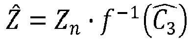
  • In the case of the Lab color space the inverse transfer function itf takes the following form: Y ^ = Y n f - 1 C 1 ^
    Figure imgb0042
    X ^ = X n f - 1 C 2 ^
    Figure imgb0043
    Z ^ = Z n f - 1 C 3 ^
    Figure imgb0044
  • According to a variant, illustrated in Fig. 3c , when the input color space is the CIEXYZ color space (C1=Y, C2=X and C3=Z) and when an integer (quantized) version (Dx , Dy , Dz ) of the triplets (X, Y, Z) is available rather than the triplets (X, Y, Z) of floating point values, the method further comprises obtaining triplets (X', Y', Z') of color picture data by inverse quantizing the triplets (Dx , Dy , Dz) according to equations (13), and color differences are encoded from the triplets (X', Y', Z') according to the equations (11) and (12): = IQx D x = IQy D y = IQz D z
    Figure imgb0045
  • According to a non-restrictive example, the modules IQx, IQy, IQz, usually called inverse code mapping in SMPTE ST 2085, and which are configured to implement the inverse quantization of equations (13), takes the following form: = Dx 2 n - 10 - 64
    Figure imgb0046
    = Dy 2 n - 10 - 64
    Figure imgb0047
    = Dz 2 n - 10 - 64
    Figure imgb0048
  • Note that (X, Y, Z) are triplets of linear data, i.e. this data is proportional to the amount of light received by a given sensor in each component (X,Y,Z), and (X', Y', Z') are triplets of non-linear data, i.e. data represented after having transformed each linear light component (X,Y,Z) with a non-linear function (perceptual curve). Consequently, when the triplets (X', Y', Z') are considered as input of the method for encoding color differences, the color differences are calculated in a non-linear domain.
  • Encoding color differences for color picture data may be used in combination with any encoding/decoding color picture data.
  • According to an embodiment of the encoding/decoding scheme, as illustrated in Fig. 4a and 4b , the encoding scheme comprises a module Q1 configured to obtain a first component D D 1 by applying a quantizing to the component E D 1 (process PP) and a module IQ1 configured to apply an inverse-quantizing to the first component D D 1 (process IPP).
  • Moreover, the encoding scheme comprises modules Q2 and Q3 configured to obtain components D D 2 and D D 3 by applying a quantizing to the components E D 2 and E D 3 .
  • The triplets (D D 1 , D D 2 , D D3) of integer color picture data are then input of an encoder ENC1 adapted to encode these triplets of color picture data into a bitstream F.
  • According to an embodiment of the decoding scheme, illustrated in Fig. 4b , the decoding scheme comprises a decoder DEC1 configured to obtain the components D D 1 ^ D D 2 ^ D D 3 ^
    Figure imgb0049
    of integer color picture data by decoding the bitstream F and, the decoding scheme further comprises modules D1D2D3-to-C1C2C3 and IQ1, IQ2, IQ3 to obtain the triplets C 1 ^ C 2 ^ C 3 ^
    Figure imgb0050
    of decoded color picture from the triplets (D D1, D D2 , D D3) as described in relation with Fig. 2 .
  • Note that according to this embodiment, the input of the encoder ENC1 and the output of the decoder DEC1 are integer point values.
  • According to an embodiment of the encoding/decoding scheme, as illustrated in Fig. 4c and 4d , the encoding scheme comprises an encoder E configured to obtain a first component by encoding the component E D 1 (process PP) and a decoder D configured to decode the first component (process IPP).
  • Moreover, the encoding scheme comprises an encoder ENC2 adapted to encode the triplets (E D 1 , E D 2 , E D 3 ) of floating point color picture data into a bitstream F.
  • According to a variant, only the components (E D 2 , E D 3 ) are processed by the encoder ENC2, since E D 1 has already been encoded.
  • According to a variant of this embodiment, the encoding scheme comprises means for calculating a residual, called component E D 1 , of the component C1 of color picture data.
  • When the component C1 is the luma component of the color picture data, such a residual may be calculated by subtracting a low spatial frequency version of the luma component of the color picture data to said luma component of the color picture data.
  • Such a residual may also be calculated by dividing the luma component of the color picture data by a backlight component.
  • According to an embodiment of the decoding scheme, illustrated in Fig. 4d , the decoding scheme comprises a decoder DEC2 configured to obtain the triplets E D 1 ^ E D 2 ^ E D 3 ^
    Figure imgb0051
    of decoded color picture, and the decoding scheme further comprises modules D1D2D3-to-C1C2C3 to obtain the triplets C 1 ^ C 2 ^ C 3 ^
    Figure imgb0052
    of decoded color picture from the triplets E D 1 ^ E D 2 ^ E D 3 ^
    Figure imgb0053
    as described in relation with Fig. 2 .
  • Note that according to this embodiment, the input of the encoder ENC2 and the output of the decoder DEC2 are floating point values.
  • According to an embodiment of the encoding/decoding scheme, as illustrated in Fig. 4e , the encoding scheme comprises a module Q1 configured to obtain an intermediate component by applying a quantizing to the component E D 1 and an encoder E configured to obtain a first component by encoding said intermediate component (process PP). The encoding scheme further comprises a decoder D configured to decode the first component and a module IQ1 configured to apply an inverse-quantizing to the first decoded component (process IPP).
  • Moreover, the encoding scheme comprises modules Q2 and Q3 configured to obtain components D D 2 and D D 3 by applying a quantizing to the components E D 2 and E D 3 .
  • The triplets (D D1, D D2 , D D3) of integer color picture data are then input of an encoder ENC1 adapted to encode these triplets of color picture data into a bitstream F.
  • The decoding scheme is the same as described in Fig. 4b .
  • The decoder D (respectively DEC1, DEC2) is configured to decode data which have been encoded by the encoder D (respectively ENC1, ENC2). The encoder E and/or ENC1 and/or ENC2 (and decoder D and/or DEC1 and/or DEC2) may be block-based processing.
  • The encoders E and/or ENC1 and/or ENC2 (and decoder E and/or DEC1 and/or DEC2) is not limited to a specific encoder (decoder).
  • The encoder E and/or ENC1 and/or ENC2 (and decoder D and/or DEC1 and/or DEC2) is not limited to a specific encoder which may be, for example, an image/video coder with loss like JPEG, JPEG2000, MPEG2, HEVC recommendation ("High Efficiency Video Coding", SERIES H: AUDIOVISUAL AND MULTIMEDIA SYSTEMS, Recommendation ITU-T H.265, Telecommunication Standardization Sector of ITU, April 2013) or H264/AVC recommendation ("Advanced video coding for generic audiovisual Services", SERIES H: AUDIOVISUAL AND MULTIMEDIA SYSTEMS, Recommendation ITU-T H.264, Telecommunication Standardization Sector of ITU, February 2014)).
  • On Fig. 1-4e , the modules are functional units, which may or not be in relation with distinguishable physical units. For example, these modules or some of them may be brought together in a unique component or circuit, or contribute to functionalities of a software. A contrario, some modules may potentially be composed of separate physical entities. The apparatus which are compatible with the invention are implemented using either pure hardware, for example using dedicated hardware such ASIC or FPGA or VLSI, respectively «Application Specific Integrated Circuit », « Field-Programmable Gate Array », « Very Large Scale Integration », or from several integrated electronic components embedded in a device or from a blend of hardware and software components.
  • Fig. 5 represents an exemplary architecture of a device 50 which may be configured to implement a method described in relation with Fig. 3-4e .
  • Device 50 comprises following elements that are linked together by a data and address bus 51:
    • a microprocessor 52 (or CPU), which is, for example, a DSP (or Digital Signal Processor);
    • a ROM (or Read Only Memory) 53;
    • a RAM (or Random Access Memory) 54;
    • an I/O interface 55 for reception of data to transmit, from an application; and
    • a battery 56.
  • According to a variant, the battery 56 is external to the device. In each of mentioned memory, the word « register » used in the specification can correspond to area of small capacity (some bits) or to very large area (e.g. a whole program or large amount of received or decoded data). ROM 53 comprises at least a program and parameters. Algorithm of the methods according to the invention is stored in the ROM 53. When switched on, the CPU 52 uploads the program in the RAM and executes the corresponding instructions.
  • RAM 54 comprises, in a register, the program executed by the CPU 52 and uploaded after switch on of the device 50, input data in a register, intermediate data in different states of the method in a register, and other variables used for the execution of the method in a register.
  • The implementations described herein may be implemented in, for example, a method or a process, an apparatus, a software program, a data stream, or a signal. Even if only discussed in the context of a single form of implementation (for example, discussed only as a method or a device), the implementation of features discussed may also be implemented in other forms (for example a program). An apparatus may be implemented in, for example, appropriate hardware, software, and firmware. The methods may be implemented in, for example, an apparatus such as, for example, a processor, which refers to processing devices in general, including, for example, a computer, a microprocessor, an integrated circuit, or a programmable logic device. Processors also include communication devices, such as, for example, computers, cell phones, portable/personal digital assistants ("PDAs"), and other devices that facilitate communication of information between end-users.
  • According to a specific embodiment of encoding or encoder, the triplets (C1, C2, C3) or (X, Y, Z) or (Dx, Dy, Dz) of color picture data are obtained from a source. For example, the source belongs to a set comprising:
    • a local memory (53 or 54), e.g. a video memory or a RAM (or Random Access Memory), a flash memory, a ROM (or Read Only Memory), a hard disk ;
    • a storage interface (55), e.g. an interface with a mass storage, a RAM, a flash memory, a ROM, an optical disc or a magnetic support;
    • a communication interface (55), e.g. a wireline interface (for example a bus interface, a wide area network interface, a local area network interface) or a wireless interface (such as a IEEE 802.11 interface or a Bluetooth® interface); and
    • a picture capturing circuit (e.g. a sensor such as, for example, a CCD (or Charge-Coupled Device) or CMOS (or Complementary Metal-Oxide-Semiconductor)).
  • According to different embodiments of the decoding or decoder, the output triplets (X̂,Ŷ,Ẑ) or C 1 ^ C 2 ^ C 3 ^
    Figure imgb0054
    of color picture data are sent to a destination; specifically, the destination belongs to a set comprising:
    • a local memory (53 or 54), e.g. a video memory or a RAM, a flash memory, a hard disk ;
    • a storage interface (55), e.g. an interface with a mass storage, a RAM, a flash memory, a ROM, an optical disc or a magnetic support;
    • a communication interface (55), e.g. a wireline interface (for example a bus interface (e.g. USB (or Universal Serial Bus)), a wide area network interface, a local area network interface, a HDMI (High Definition Multimedia Interface) interface) or a wireless interface (such as a IEEE 802.11 interface, WiFi ® or a Bluetooth ® interface); and
    • a display.
  • According to different embodiments of encoding or encoder, the bitstream F is sent to a destination. As an example, the bitstream F is stored in a local or remote memory, e.g. a video memory (54) or a RAM (54), a hard disk (53). In a variant, the bitstream is sent to a storage interface (55), e.g. an interface with a mass storage, a flash memory, ROM, an optical disc or a magnetic support and/or transmitted over a communication interface (55), e.g. an interface to a point to point link, a communication bus, a point to multipoint link or a broadcast network.
  • According to different embodiments of decoding or decoder, the bitstream F is obtained from a source. Exemplarily, the bitstream is read from a local memory, e.g. a video memory (54), a RAM (54), a ROM (53), a flash memory (53) or a hard disk (53). In a variant, the bitstream is received from a storage interface (55), e.g. an interface with a mass storage, a RAM, a ROM, a flash memory, an optical disc or a magnetic support and/or received from a communication interface (55), e.g. an interface to a point to point link, a bus, a point to multipoint link or a broadcast network.
  • According to different embodiments, device 50 being configured to implement an method described in relation with Fig. 3, 3a, 3c , 4a, 4c or 4e , belongs to a set comprising:
    • a mobile device ;
    • a communication device ;
    • a game device ;
    • a tablet (or tablet computer) ;
    • a laptop ;
    • a still picture camera;
    • a video camera ;
    • an encoding chip;
    • a still picture server; and
    • a video server (e.g. a broadcast server, a video-on-demand server or a web server).
  • According to different embodiments, device 50 being configured to implement a decoding method described in relation with Fig. 2, 3b , 4b or 4d , belongs to a set comprising:
    • a mobile device ;
    • a communication device ;
    • a game device ;
    • a set top box;
    • a TV set;
    • a tablet (or tablet computer) ;
    • a laptop ;
    • a display and
    • a decoding chip.
  • According to an embodiment illustrated in Fig. 6 , in a transmission context between two remote devices A and B over a communication network NET, the device A comprises means which are configured to implement a method as described in relation with the Fig. 3, 3a, 3c , 4a, 4c or 4e and the device B comprises means which are configured to implement a method for decoding as described in relation with Fig. 2, 3b , 4b or 4d .
  • According to a variant of the disclosure, the network is a broadcast network, adapted to broadcast still pictures or video pictures from device A to decoding devices including the device B.
  • Implementations of the various processes and features described herein may be embodied in a variety of different equipment or applications, particularly, for example, equipment or applications. Examples of such equipment include an encoder, a decoder, a post-processor processing output from a decoder, a pre-processor providing input to an encoder, a video coder, a video decoder, a video codec, a web server, a set-top box, a laptop, a personal computer, a cell phone, a PDA, and other communication devices. As should be clear, the equipment may be mobile and even installed in a mobile vehicle.
  • Additionally, the methods may be implemented by instructions being performed by a processor, and such instructions (and/or data values produced by an implementation) may be stored on a computer readable storage medium. A computer readable storage medium can take the form of a computer readable program product embodied in one or more computer readable medium(s) and having computer readable program code embodied thereon that is executable by a computer. A computer readable storage medium as used herein is considered a non-transitory storage medium given the inherent capability to store the information therein as well as the inherent capability to provide retrieval of the information therefrom. A computer readable storage medium can be, for example, but is not limited to, an electronic, magnetic, optical, electromagnetic, infrared, or semiconductor system, apparatus, or device, or any suitable combination of the foregoing. It is to be appreciated that the following, while providing more specific examples of computer readable storage mediums to which the present principles can be applied, is merely an illustrative and not exhaustive listing as is readily appreciated by one of ordinary skill in the art: a portable computer diskette; a hard disk; a read-only memory (ROM); an erasable programmable read-only memory (EPROM or Flash memory); a portable compact disc read-only memory (CD-ROM); an optical storage device; a magnetic storage device; or any suitable combination of the foregoing.
  • The instructions may form an application program tangibly embodied on a processor-readable medium.
  • Instructions may be, for example, in hardware, firmware, software, or a combination. Instructions may be found in, for example, an operating system, a separate application, or a combination of the two. A processor may be characterized, therefore, as, for example, both a device configured to carry out a process and a device that includes a processor-readable medium (such as a storage device) having instructions for carrying out a process. Further, a processor-readable medium may store, in addition to or in lieu of instructions, data values produced by an implementation.
  • As will be evident to one of skill in the art, implementations may produce a variety of signals formatted to carry information that may be, for example, stored or transmitted. The information may include, for example, instructions for performing a method, or data produced by one of the described implementations. For example, a signal may be formatted to carry as data the rules for writing or reading the syntax of a described embodiment, or to carry as data the actual syntax-values written by a described embodiment. Such a signal may be formatted, for example, as an electromagnetic wave (for example, using a radio frequency portion of spectrum) or as a baseband signal. The formatting may include, for example, encoding a data stream and modulating a carrier with the encoded data stream. The information that the signal carries may be, for example, analog or digital information. The signal may be transmitted over a variety of different wired or wireless links, as is known. The signal may be stored on a processor-readable medium.
  • A number of implementations have been described. Nevertheless, it will be understood that various modifications may be made. For example, elements of different implementations may be combined, supplemented, modified, or removed to produce other implementations. Additionally, one of ordinary skill will understand that other structures and processes may be substituted for those disclosed and the resulting implementations will perform at least substantially the same function(s), in at least substantially the same way(s), to achieve at least substantially the same result(s) as the implementations disclosed. Accordingly, these and other implementations are contemplated by this application.

Claims (16)

  1. A method for encoding color differences for color picture data comprising three components C1, C2 and C3 of an input color space, said color differences comprising a first component defined from the component C1, a first color difference component defined from the component C2, and a second color difference component defined from the component C3, characterized in that it further comprises:
    - obtaining a first component by applying a process to the component C1;
    - obtaining a second component by applying the inverse process to the first component; and
    - the first and second color difference components are further defined from the second component.
  2. The method of claim 1, wherein the process applied to the component C1 comprises a quantizing of the component C1 and the inverse process applied to the first component comprises an inverse-quantizing of the first component.
  3. The method of claim 1, wherein the process applied to the component C1 comprises an encoding of the component C1 and the inverse process applied to the first component comprises a decoding of the first component.
  4. The method of claim 1, wherein the process applied to the component C1 comprises a quantizing of the component C1 followed by an encoding of the quantized component C1 and the inverse process applied to the first component comprises a decoding of the first component followed by an inverse-quantizing of the decoded component.
  5. The method of one of claims 1-4, wherein the method further comprises applying a transfer function on the color picture data in order to obtain non-linear color picture data.
  6. The method of one of claims 1-5, wherein the method further comprises inverse-quantizing each component of the color picture data before applying the process to the component C1.
  7. The method of claims 1-6, wherein the input color space is the CIEXYZ color space or the YDzDx color space.
  8. A method for encoding color picture data which comprises an encoding color differences for said color picture data according to one of the claims 1-7.
  9. A method of claim 8, wherein obtaining a first component by applying a process to the component C1 comprises calculating a residual of the component C1 of color picture data.
  10. The method of claim 9, wherein when the component C1 is the luma component of the color picture color data, the residual of the luma component of color picture data is calculated by substracting a low spatial frequency version of the luma component of the color picture data to said luma component of the color picture.
  11. The method of claim 9, wherein when the component C1 is the luma component of the color picture color data, the residual of the luma component of color picture data is calculated by dividing the luma component of the color picture data by a backlight component.
  12. A device for encoding color differences for color picture data comprising three components C1, C2 and C3 of an input color space, said color differences comprising a first component defined from the component C1, a first color difference component defined from the component C2, and a second color difference component defined from the component C3, characterized in that the device comprises a processor configured to:
    - obtain a first component by applying a process to the component C1;
    - obtain a second component by applying the inverse process to the first component; and
    - to define the first and second color difference components from the second component.
  13. A device for encoding picture data which comprises a processor configured for encoding color differences according to a method of one of the claims 1-7.
  14. A computer program product comprising program code instructions to execute the steps of the encoding method according to claim 1 or 7 when this program is executed on a computer.
  15. A processor readable medium having stored therein instructions for causing a processor to perform at least the steps of the encoding method according to claim 1 or 7.
  16. Non-transitory storage medium carrying instructions of program code for executing steps of the method according to one of claims 1 to 7, when said program is executed on a computing device.
EP15305887.0A 2015-06-10 2015-06-10 Method and device for encoding color differences for color picture data Withdrawn EP3104610A1 (en)

Priority Applications (8)

Application Number Priority Date Filing Date Title
EP15305887.0A EP3104610A1 (en) 2015-06-10 2015-06-10 Method and device for encoding color differences for color picture data
TW105117485A TW201711474A (en) 2015-06-10 2016-06-03 Method and device for obtaining color difference components for color picture data
PCT/EP2016/062824 WO2016198364A1 (en) 2015-06-10 2016-06-07 Method and device for obtaining color difference components for color picture data
CN201680033694.6A CN107950027A (en) 2015-06-10 2016-06-07 Method and apparatus for obtaining color difference components on color picture data
KR1020177035227A KR20180017018A (en) 2015-06-10 2016-06-07 Method and device for obtaining chrominance components for color picture data
JP2017563181A JP2018524869A (en) 2015-06-10 2016-06-07 Method and apparatus for obtaining color difference component of color picture data
EP16732462.3A EP3308546A1 (en) 2015-06-10 2016-06-07 Method and device for obtaining color difference components for color picture data
US15/735,174 US10757427B2 (en) 2015-06-10 2016-06-07 Method and device for obtaining color difference components for color picture data

Applications Claiming Priority (1)

Application Number Priority Date Filing Date Title
EP15305887.0A EP3104610A1 (en) 2015-06-10 2015-06-10 Method and device for encoding color differences for color picture data

Publications (1)

Publication Number Publication Date
EP3104610A1 true EP3104610A1 (en) 2016-12-14

Family

ID=53488269

Family Applications (2)

Application Number Title Priority Date Filing Date
EP15305887.0A Withdrawn EP3104610A1 (en) 2015-06-10 2015-06-10 Method and device for encoding color differences for color picture data
EP16732462.3A Ceased EP3308546A1 (en) 2015-06-10 2016-06-07 Method and device for obtaining color difference components for color picture data

Family Applications After (1)

Application Number Title Priority Date Filing Date
EP16732462.3A Ceased EP3308546A1 (en) 2015-06-10 2016-06-07 Method and device for obtaining color difference components for color picture data

Country Status (7)

Country Link
US (1) US10757427B2 (en)
EP (2) EP3104610A1 (en)
JP (1) JP2018524869A (en)
KR (1) KR20180017018A (en)
CN (1) CN107950027A (en)
TW (1) TW201711474A (en)
WO (1) WO2016198364A1 (en)

Citations (3)

* Cited by examiner, † Cited by third party
Publication number Priority date Publication date Assignee Title
WO2008004768A1 (en) * 2006-07-04 2008-01-10 Samsung Electronics Co., Ltd. Image encoding/decoding method and apparatus
WO2012160797A1 (en) * 2011-05-20 2012-11-29 Panasonic Corporation Methods and apparatuses for encoding and decoding video using inter-color-plane prediction
WO2014166965A1 (en) * 2013-04-08 2014-10-16 Fraunhofer-Gesellschaft zur Förderung der angewandten Forschung e.V. Inter-component prediction

Family Cites Families (12)

* Cited by examiner, † Cited by third party
Publication number Priority date Publication date Assignee Title
JPH0662431A (en) 1992-08-14 1994-03-04 Oki Electric Ind Co Ltd Quantizing/inverse quantizing method for color picture element data
US6804299B2 (en) * 2001-06-15 2004-10-12 Microsoft Corporation Methods and systems for reducing requantization-originated generational error in predictive video streams using motion compensation
US20030012431A1 (en) * 2001-07-13 2003-01-16 Irvine Ann C. Hybrid lossy and lossless compression method and apparatus
US20090123066A1 (en) * 2005-07-22 2009-05-14 Mitsubishi Electric Corporation Image encoding device, image decoding device, image encoding method, image decoding method, image encoding program, image decoding program, computer readable recording medium having image encoding program recorded therein,
KR101291196B1 (en) 2008-01-25 2013-07-31 삼성전자주식회사 Video encoding method and apparatus, and video decoding method and apparatus
JP4650512B2 (en) * 2008-03-28 2011-03-16 セイコーエプソン株式会社 Image coding apparatus and integrated circuit device
KR100968371B1 (en) * 2008-04-25 2010-07-06 주식회사 코아로직 Method and apparatus for decoding video
CN101534454B (en) 2009-04-29 2010-11-10 天津大学 A color difference signal non-linear quantization method for expansion of digital television color gamut
KR101763113B1 (en) * 2010-12-06 2017-08-01 에스케이 텔레콤주식회사 Video Encoding/Decoding Method and Apparatus for Noise Component in Spatial Domain
US9288500B2 (en) 2011-05-12 2016-03-15 Texas Instruments Incorporated Luma-based chroma intra-prediction for video coding
WO2014007514A1 (en) 2012-07-02 2014-01-09 엘지전자 주식회사 Method for decoding image and apparatus using same
US9414054B2 (en) * 2012-07-02 2016-08-09 Microsoft Technology Licensing, Llc Control and use of chroma quantization parameter values

Patent Citations (3)

* Cited by examiner, † Cited by third party
Publication number Priority date Publication date Assignee Title
WO2008004768A1 (en) * 2006-07-04 2008-01-10 Samsung Electronics Co., Ltd. Image encoding/decoding method and apparatus
WO2012160797A1 (en) * 2011-05-20 2012-11-29 Panasonic Corporation Methods and apparatuses for encoding and decoding video using inter-color-plane prediction
WO2014166965A1 (en) * 2013-04-08 2014-10-16 Fraunhofer-Gesellschaft zur Förderung der angewandten Forschung e.V. Inter-component prediction

Non-Patent Citations (4)

* Cited by examiner, † Cited by third party
Title
"Advanced video coding for generic audiovisual Services", SERIES H: AUDIOVISUAL AND MULTIMEDIA SYSTEMS, RECOMMENDATION ITU-T H.264, TELECOMMUNICATION STANDARDIZATION SECTOR OF ITU, February 2014 (2014-02-01)
"FCD SMPTE Standard High Dynamic Range Electro-Optical Transfer Function of Mastering Reference Displays", SMPTE ST2084:201 X, VERSION 1.24, 18 June 2014 (2014-06-18)
"High Efficiency Video Coding", SERIES H: AUDIOVISUAL AND MULTIMEDIA SYSTEMS, RECOMMENDATION ITU-T H.265, TELECOMMUNICATION STANDARDIZATION SECTOR OF ITU, April 2013 (2013-04-01)
LASSERRE S ET AL: "High Dynamic Range video coding", 16. JCT-VC MEETING; 9-1-2014 - 17-1-2014; SAN JOSE; (JOINT COLLABORATIVE TEAM ON VIDEO CODING OF ISO/IEC JTC1/SC29/WG11 AND ITU-T SG.16 ); URL: HTTP://WFTP3.ITU.INT/AV-ARCH/JCTVC-SITE/,, no. JCTVC-P0159-v3, 15 January 2014 (2014-01-15), XP030115678 *

Also Published As

Publication number Publication date
WO2016198364A1 (en) 2016-12-15
TW201711474A (en) 2017-03-16
EP3308546A1 (en) 2018-04-18
JP2018524869A (en) 2018-08-30
CN107950027A (en) 2018-04-20
US10757427B2 (en) 2020-08-25
US20180160128A1 (en) 2018-06-07
KR20180017018A (en) 2018-02-20

Similar Documents

Publication Publication Date Title
US20250159212A1 (en) Method and device for encoding/decoding an image unit comprising image data represented by a luminance channel and at least one chrominance channel
EP3349451A1 (en) Method and apparatus for selecting a coding mode used for encoding/decoding a residual block
US20200219236A1 (en) Method and device for reconstructing an hdr image
CN115280786B (en) Advanced constraint tags for controlling local colorimetric parameters
EP3096520B1 (en) A method for encoding/decoding a picture block
CN114930344A (en) Data stream compression
EP3026908A1 (en) Method and device for quantizing and de-quantizing a picture using scaling factors for chrominance based on luminance
US10972698B2 (en) Method and device for selecting a process to be applied on video data from a set of candidate processes driven by a common set of information data
US10757427B2 (en) Method and device for obtaining color difference components for color picture data
US10148958B2 (en) Method and device for encoding and decoding a HDR picture and a LDR picture
EP3035685A1 (en) A device and a method for encoding an image and corresponding decoding method and decoding device
EP3146718B1 (en) Method and device for scalable encoding of a high dynamic range frame and/or decoding a bitstream representing such a frame
HK40078328A (en) Method and device for encoding/decoding an image unit comprising image data represented by a luminance channel and at least one chrominance channel
WO2015193116A1 (en) Method and device for decoding a hdr picture from a bitstream representing a ldr picture and an illumination picture
WO2015177123A1 (en) Method and device for encoding a frame and/or decoding a bitstream representing a frame
WO2015177126A1 (en) Method and device for encoding a frame and/or decoding a bitstream representing a frame
CN114788275A (en) Derivation of quantization matrices for joint Cb-Cr coding
WO2015193117A1 (en) Method and device for decoding a hdr picture from a bitstream representing a ldr picture and an illumination picture
WO2015193115A1 (en) Method and device for decoding a hdr picture from a bitstream representing a ldr picture and an illumination picture
WO2015177119A1 (en) Method and device for encoding a frame and/or decoding a bitstream representing a frame
WO2015177125A1 (en) Method and device for encoding a frame and/or decoding a bitstream representing a frame

Legal Events

Date Code Title Description
PUAI Public reference made under article 153(3) epc to a published international application that has entered the european phase

Free format text: ORIGINAL CODE: 0009012

AK Designated contracting states

Kind code of ref document: A1

Designated state(s): AL AT BE BG CH CY CZ DE DK EE ES FI FR GB GR HR HU IE IS IT LI LT LU LV MC MK MT NL NO PL PT RO RS SE SI SK SM TR

AX Request for extension of the european patent

Extension state: BA ME

STAA Information on the status of an ep patent application or granted ep patent

Free format text: STATUS: THE APPLICATION IS DEEMED TO BE WITHDRAWN

18D Application deemed to be withdrawn

Effective date: 20170615