EP3104476A1 - Spark plug - Google Patents
Spark plug Download PDFInfo
- Publication number
- EP3104476A1 EP3104476A1 EP16173146.8A EP16173146A EP3104476A1 EP 3104476 A1 EP3104476 A1 EP 3104476A1 EP 16173146 A EP16173146 A EP 16173146A EP 3104476 A1 EP3104476 A1 EP 3104476A1
- Authority
- EP
- European Patent Office
- Prior art keywords
- projection
- recess
- noble metal
- spark plug
- metal tip
- Prior art date
- Legal status (The legal status is an assumption and is not a legal conclusion. Google has not performed a legal analysis and makes no representation as to the accuracy of the status listed.)
- Granted
Links
Images


Classifications
-
- H—ELECTRICITY
- H01—ELECTRIC ELEMENTS
- H01T—SPARK GAPS; OVERVOLTAGE ARRESTERS USING SPARK GAPS; SPARKING PLUGS; CORONA DEVICES; GENERATING IONS TO BE INTRODUCED INTO NON-ENCLOSED GASES
- H01T13/00—Sparking plugs
- H01T13/20—Sparking plugs characterised by features of the electrodes or insulation
- H01T13/39—Selection of materials for electrodes
-
- H—ELECTRICITY
- H01—ELECTRIC ELEMENTS
- H01T—SPARK GAPS; OVERVOLTAGE ARRESTERS USING SPARK GAPS; SPARKING PLUGS; CORONA DEVICES; GENERATING IONS TO BE INTRODUCED INTO NON-ENCLOSED GASES
- H01T13/00—Sparking plugs
- H01T13/20—Sparking plugs characterised by features of the electrodes or insulation
- H01T13/32—Sparking plugs characterised by features of the electrodes or insulation characterised by features of the earthed electrode
-
- H—ELECTRICITY
- H01—ELECTRIC ELEMENTS
- H01T—SPARK GAPS; OVERVOLTAGE ARRESTERS USING SPARK GAPS; SPARKING PLUGS; CORONA DEVICES; GENERATING IONS TO BE INTRODUCED INTO NON-ENCLOSED GASES
- H01T13/00—Sparking plugs
- H01T13/02—Details
- H01T13/16—Means for dissipating heat
Definitions
- the recess 63 since the recess 63 is formed in the melted portion 62, the recess 63 can be easily formed simply by adjusting the output of the laser device. Therefore, the recess 63 can be formed without a large increase in the manufacturing cost. In addition, in the present embodiment, since the center electrode 20 includes the noble metal tip 61, the durability of the center electrode 20 can be increased.
- the recess 63 is formed in the projection 60 during the laser welding process.
- the recess 63 may instead be formed by, for example, a cutting process using a drill or the like or a punching process.
Landscapes
- Spark Plugs (AREA)
Abstract
Description
- The present invention relates to a spark plug.
- The ignitability of spark plugs has been increased by, for example, increasing the ignition energy applied to the spark plug (see PTL 1).
- PTL 1: Japanese Unexamined Patent Application Publication No.
2013-108465 - However, to increase the ignition energy, an ignition coil or the like capable of generating a large amount of energy is required, and therefore the cost of the entire ignition system is increased.
- Accordingly, a technology for increasing the ignitability of a spark plug with a simple structure is in demand.
- The present invention has been made to solve the above-described problem, and can be embodied in the following forms.
- (1) An aspect of the present invention provides a spark plug. The spark plug includes a metal shell having a tubular shape; an insulator having an axial hole that extends along an axial line, at least a portion of a periphery of the insulator being held by the metal shell; a center electrode disposed in the axial hole; and a ground electrode that is fixed to the metal shell and that forms a discharge gap between the ground electrode and the center electrode. At least one of the center electrode and the ground electrode includes a projection having a columnar shape, the projection projecting toward the other of the center electrode and the ground electrode and forming the discharge gap. A portion of a side surface of the projection has a recess. The projection includes a noble metal tip having a cylindrical shape disposed at a side adjacent to the discharge gap, and a melted portion disposed at a side of the noble metal tip opposite to the side adjacent to the discharge gap, the melted portion being formed by melting the noble metal tip and an electrode base material. The recess is formed in the melted portion. When D is a depth of the recess from a side surface of the noble metal tip and R is a diameter of the noble metal tip, following condition (1) is satisfied:

The spark plug according to this aspect is configured such that the recess is formed in a portion of the side surface of the projection that projects toward the discharge gap. The recess suppresses heat conduction from the end of the projection, so that the temperature of the end of the projection is maintained high. As a result, the flame quenching effect of the electrode is suppressed, and the ignitability is increased. Thus, the ignitability of the spark plug can be increased with a simple structure. Since the recess is formed in the melted portion, the recess can be easily formed. In addition, since the projection includes the noble metal tip, the durability of the electrode can be increased. Furthermore, since the depth D of the recess and the diameter R of the noble metal tip satisfy the above condition (1), the ignitability of the spark plug can be reliably increased. - (2) In the spark plug according to the above-described aspect, when T is a dimension of an opening of the recess in a direction of a central axis of the projection, following condition (2) is satisfied:

With such a spark plug, the ignitability of the spark plug can be appropriately increased. - (3) In the spark plug according to the above-described aspect, the projection may be provided with a plurality of the recesses. With such a spark plug, the ignitability of the spark plug can be more appropriately increased.
- (4) In the spark plug according to the above-described aspect, the center electrode may include the projection. With such a spark plug, the flame quenching effect of the center electrode can be reduced.
- (5) In the spark plug according to the above-described aspect, the ground electrode may include the projection. With such a spark plug, the flame quenching effect of the ground electrode can be reduced.
- The present invention may be embodied in various forms, such as a method for manufacturing a spark plug as well as the above-described spark plug.
-
-
Fig. 1 is a partially sectioned view of a spark plug; -
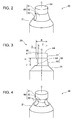
Fig. 2 is a perspective view of a front end portion of a center electrode; -
Fig. 3 illustrates the dimensions of portions of a projection; -
Fig. 4 illustrates an example in which a plurality of recesses are formed in a melted portion; -
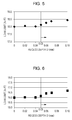
Fig. 5 is a graph showing the result of a first ignitability evaluation test; -
Fig. 6 is a graph showing the result of a second ignitability evaluation test; -
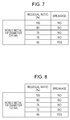
Fig. 7 shows the result of a first vibration evaluation test; -
Fig. 8 shows the result of a second vibration evaluation test; -
Fig. 9 is a graph showing the result of a third ignitability evaluation test; and -
Fig. 10 is a graph showing the result of a fourth ignitability evaluation test. -
Fig. 1 is a partially sectioned view of aspark plug 100 according to an embodiment of the present invention. Thespark plug 100 has a thin long shape that extends along an axial line O. InFig. 1 , an external front view of thespark plug 100 is shown on the right side of the axial line O, which is represented by the dotted chain line, and a sectional view of thespark plug 100 along the axial line O is shown on the left side of the axial line O. In the following description, the upper side ofFig. 1 is referred to as the front side of thespark plug 100, and the lower side ofFig. 1 as the rear side of thespark plug 100. - The
spark plug 100 includes aninsulator 10, acenter electrode 20, aground electrode 30, and ametal shell 50. Theinsulator 10 has anaxial hole 12 that extends along the axial line O, and at least a portion of the periphery of theinsulator 10 is held by ametal shell 50 having a tubular shape. Thecenter electrode 20 is disposed in theaxial hole 12. Theground electrode 30 is fixed to afront end surface 57 of themetal shell 50, and a discharge gap G is formed between thecenter electrode 20 and theground electrode 30. - The
insulator 10 is formed by sintering a ceramic material, such as alumina. Theinsulator 10 is a tubular member having theaxial hole 12 at the center. Theaxial hole 12 houses a portion of thecenter electrode 20 at the front side and a portion of aterminal 40 at the rear side. Theinsulator 10 includes acentral body portion 19 having a large diameter at the center thereof in the axial direction. A rear-side body portion 18, which provides insulation between theterminal 40 and themetal shell 50, is provided on a side of thecentral body portion 19 that is adjacent to theterminal 40. A front-side body portion 17, which has an outer diameter smaller than that of the rear-side body portion 18, is provided on a side of thecentral body portion 19 that is adjacent to thecenter electrode 20. Aleg portion 13, which has an outer diameter that is smaller than that of the front-side body portion 17 and decreases toward thecenter electrode 20, is formed on the front side of the front-side body portion 17. - The
metal shell 50 is a member having a tubular shape that surrounds and holds theinsulator 10 over a region from a portion of the rear-side body portion 18 to theleg portion 13. Themetal shell 50 is made of, for example, a low-carbon steel, and the entirety thereof is plated with, for example, nickel or zinc. Themetal shell 50 includes atool engagement portion 51, a sealingportion 54, and a threadedportion 52 in that order from the rear side. A tool used to attach thespark plug 100 to an engine head engages with thetool engagement portion 51. The threadedportion 52 has a thread that engages with a threaded hole formed in the engine head. The sealingportion 54 is flange-shaped and is provided at the base of the threadedportion 52. Anannular gasket 5, which is formed by bending a plate, is interposed between the sealingportion 54 and the engine head. Thefront end surface 57 of themetal shell 50 has an annular shape, and theleg portion 13 of theinsulator 10 and thecenter electrode 20 project through thefront end surface 57 at the center thereof. - The
metal shell 50 includes a thin crimpingportion 53 on the rear side of thetool engagement portion 51. Acompressive deformation portion 58, which is as thin as the crimpingportion 53, is provided between the sealingportion 54 and thetool engagement portion 51.Annular ring members side body portion 18 of theinsulator 10 and the inner peripheral surface of themetal shell 50 in a region from thetool engagement portion 51 to the crimpingportion 53. The space between thering members talc 9. In the manufacturing process of thespark plug 100, the crimpingportion 53 is bent inward and pressed toward the front side so that thecompressive deformation portion 58 is compressed and deformed. - Accordingly, the
insulator 10 is pressed toward the front side by thering members talc 9 in themetal shell 50, so that thetalc 9 is compressed in the direction of the axial line O and the airtightness of themetal shell 50 is increased. - A metal-shell stepped
portion 56 is formed on the inner peripheral surface of themetal shell 50 at a position where the threadedportion 52 is provided, and an insulator steppedportion 15 is provided at the proximal end of theleg portion 13 of theinsulator 10. The insulator steppedportion 15 is pressed against the metal-shell steppedportion 56 with an annular plate packing 8 interposed therebetween. The plate packing 8 ensures sufficient airtightness between themetal shell 50 and theinsulator 10, thereby preventing leakage of the combustion gas. - The
ground electrode 30 is made of a metal with high corrosion resistance. An example of a metal with high corrosion resistance is a nickel alloy containing nickel as the main component, such as Inkonel (tradename) 600 or Inconel 601. The proximal end of theground electrode 30 is welded to thefront end surface 57 of themetal shell 50. In the present embodiment, theground electrode 30 is bent at an intermediate portion thereof so that a side surface of a front end portion of theground electrode 30 faces thecenter electrode 20. Theground electrode 30 may have a two-layer structure in which copper or a copper alloy is embedded in a base material made of the above-mentioned nickel alloy. Alternatively, theground electrode 30 may have a three-layer structure in which nickel or a nickel alloy is embedded in the copper or copper alloy. Here, the main component of an object is a component with the highest percentage by mass, and the percentage by mass of the main component does not necessarily exceed 50 mass%. - The
center electrode 20 is a rod-shaped member in which acore material 22 with high thermal conductivity is embedded in anelectrode base material 21. Theelectrode base material 21 is made of a nickel alloy containing nickel as the main component, and thecore material 22 is made of copper or an alloy containing copper as the main material. - The
center electrode 20 includes aflange portion 23, which is shaped so as to project outward, at a position near the rear end thereof. Theflange portion 23 comes into contact with an axial-hole steppedportion 14, which is formed in theaxial hole 12, from the rear side, so that thecenter electrode 20 is positioned in theinsulator 10. The rear end portion of thecenter electrode 20 is electrically connected to the terminal 40 through aceramic resistor 3 and a sealingmember 4. -
Fig. 2 is a perspective view of a front end portion of thecenter electrode 20. In the present embodiment, thecenter electrode 20 includes aprojection 60 having a columnar shape at the front end thereof. Theprojection 60 projects towards the other electrode, that is, theground electrode 30, so as to form the discharge gap G. Theprojection 60 includes anoble metal tip 61 having a cylindrical shape located adjacent to the discharge gap G, and a meltedportion 62 located at a side of thenoble metal tip 61 opposite to the side adjacent to the discharge gap G. The meltedportion 62 is formed by melting theelectrode base material 21 and thenoble metal tip 61. Thenoble metal tip 61 is made of, for example, platinum (Pt), iridium (Ir), ruthenium (Ru), rhodium (Rh), or an alloy thereof. In the present embodiment, theelectrode base material 21 has a diameter greater than that of theprojection 60. The front end portion of theelectrode base material 21 is tapered and connected to the meltedportion 62. - A
recess 63 is formed in the side surface of theprojection 60. In the present embodiment, therecess 63 is formed in the meltedportion 62. The meltedportion 62 is formed by irradiating the boundary between theelectrode base material 21 and thenoble metal tip 61 with a laser beam a plurality of times by using a pulsed oscillation laser while rotating theelectrode base material 21 and thenoble metal tip 61 around the central axis C. In the present embodiment, therecess 63 is formed in the meltedportion 62 by increasing the output level of the laser beam at any one of the times the laser beam is output. To form acircular recess 63, the output level is preferably increased when the laser beam is output for the last time. The output level of the laser beam for forming therecess 63 is determined in advance so that the dimensions of therecess 63 satisfy conditions (1) and (2) described below. In the present embodiment, the central axis C of theelectrode base material 21 and thenoble metal tip 61, that is, the central axis C of theprojection 60, coincides with the axial line O. -
Fig. 3 illustrates the dimensions of portions of theprojection 60. The height H of theprojection 60, that is, the dimension from afront end surface 64 of thenoble metal tip 61 to the rear end of the meltedportion 62 along the central axis C, is generally 0.5 mm to 2.5 mm, and is 2.5 mm in the present embodiment. - In the present embodiment, when the diameter of the
noble metal tip 61 is R, the depth D of therecess 63 preferably satisfies condition (1) given below. The depth D of therecess 63 is the depth from the side surface of thenoble metal tip 61 in the direction toward the central axis C. The diameter R of thenoble metal tip 61 is 0.17 mm or more.
- In addition, in the present embodiment, when T is the dimension of the opening of the
recess 63 in the direction of the central axis C of theprojection 60, the dimension T preferably satisfies condition (2) given below. In the following description, the dimension T is referred to as an opening height T.
- The reason why the dimensions of the
recess 63 of theprojection 60 preferably satisfy the above conditions (1) and (2) will be described below. - The
spark plug 100 according to the above-described embodiment is configured such that therecess 63 is formed in a portion of the side surface of theprojection 60 provided at the front end of thecenter electrode 20. Therecess 63 suppresses heat conduction from the front end of thecenter electrode 20, so that the temperature of the front end of thecenter electrode 20 is maintained high. As a result, the flame quenching effect of thecenter electrode 20 is suppressed, and the ignitability is increased. More specifically, therecess 63 suppresses heat conduction from a high temperature portion 65 (seeFig. 3 ), which is a portion on the front side of therecess 63 along the central axis C, so that the temperature of the electrode surface of that portion is locally increased and the thermionic emission performance is increased accordingly. This facilitates electric discharge around thehigh temperature portion 65, and initial flame is easily formed around thehigh temperature portion 65. Since the temperature is higher at thehigh temperature portion 65 than at other portions, the flame quenching effect is reduced and the ignitability is increased. Therefore, according to the present embodiment, the ignitability of thespark plug 100 can be increased with a simple structure in which therecess 63 is formed in theprojection 60 provided at the front end of thecenter electrode 20. In the present embodiment, the recess is formed in a portion of the side surface of theprojection 60, and is not formed over the entire periphery of the side surface. Therefore, compared to the case in which the recess is formed over the entire periphery, the local high-temperature portion can be more easily formed and the ignitability can be more effectively increased. - In the present embodiment, since the
recess 63 is formed in the meltedportion 62, therecess 63 can be easily formed simply by adjusting the output of the laser device. Therefore, therecess 63 can be formed without a large increase in the manufacturing cost. In addition, in the present embodiment, since thecenter electrode 20 includes thenoble metal tip 61, the durability of thecenter electrode 20 can be increased. - In the present embodiment, a
single recess 63 is formed in theprojection 60. However, a plurality ofrecesses 63 may instead be formed.Fig. 4 illustrates an example in which tworecesses 63 are formed in theprojection 60. In the case where a plurality ofrecesses 63 are formed, therecesses 63 may be arranged around the central axis C of theprojection 60 with constant intervals therebetween along the side surface of theprojection 60. Therecesses 63 may be disposed near each other so as not to be in contact with each other. - In the present embodiment, the expression "the
recess 63 is formed in a portion of the side surface of theprojection 60" means that no recess is formed in a portion of the entire periphery of the side surface of theprojection 60 other than the portion in which therecess 63 is formed. In other words, the outer diameter of the portion other than the portion in which therecess 63 is formed is constant, or the difference between the outer diameter and the tip diameter R is less than 0.05 mm. - The reason why the dimensions of the
recess 63 preferably satisfy the above conditions (1) and (2) will be described with reference to the results of various tests. -
Fig. 5 is a graph showing the result of a first ignitability evaluation test. In the first ignitability evaluation test, a plurality of samples of thespark plug 100 in which the depth D of therecess 63 was set to different values (depth D = 0 mm, 0.02 mm, 0.04 mm, 0.05 mm, 0.06 mm, 0.07 mm, and 0.10 mm) were prepared. The samples were attached to a 4-cylinder engine with a displacement of 2.0 liters, and the engine was operated at a rotational speed of 1500 rpm with the ignition timing set to the minimum advance for best torque (MBT) timing. The air/fuel ratio was gradually increased, that is, the fuel content was gradually reduced, and the coefficient of variation (COV) in combustion was measured for each air/fuel ratio. The air/fuel ratio (A/F) at the time when the coefficient of variation in combustion exceeded 5% is plotted in the graph as the lean limit. In all of the samples used in this test, the diameter R of thenoble metal tip 61 was 0.4 mm, the opening height T of the recess was 0.2 mm, the height H of theprojection 60 was 2.5 mm, and the number of recesses was 1. Each of the values plotted inFig. 5 is the average of the results of three measurements performed for each sample. - As is clear from
Fig. 5 , the result of the first ignitability evaluation test shows that, when the depth D of therecess 63 is 0.05 mm or more, the lean limit is greater and the ignitability is higher than when the depth D of therecess 63 is less than 0.05 mm. -
Fig. 6 is a graph showing the result of a second ignitability evaluation test. In the second ignitability evaluation test, a test similar to the first ignitability evaluation test was performed by using samples similar to the samples of the first ignitability evaluation test except that the diameter R of thenoble metal tip 61 was 1.2 mm. Each of the values plotted inFig. 6 is the average of the results of three measurements performed for each sample. - As is clear from
Fig. 6 , similar to the first ignitability evaluation test, the result of the second ignitability evaluation test also shows that when the depth D of therecess 63 is 0.05 mm or more, the lean limit is greater and the ignitability is higher than when the depth D of therecess 63 is less than 0.05 mm. Thus, the first and second ignitability evaluation tests confirmed that the lower limit of the depth D of therecess 63 in the above condition (1) is preferably 0.05 mm. -
Fig. 7 shows the result of a first vibration evaluation test. In the first vibration evaluation test, a plurality of samples in which the diameter R of thenoble metal tip 61 was 0.4 mm and the depth D of therecess 63 was changed so that the residual ratio of theprojection 60 relative to the diameter R was changed (residual ratio = 65%, 70%, 75%, 80%, and 100%) were prepared. The residual ratio is the ratio of the value Z (seeFig. 3 ) obtained by subtracting the depth D of therecess 63 from the diameter R of thenoble metal tip 61 relative to the diameter R. In this test, the samples were attached to an ultrasonic vibrator and vibrated at a vibration frequency of 27.3 kHz for 600 seconds. The frequency of 27.3 kHz is determined based on the resonance frequency of a common noble metal tip. InFig. 7 , which shows the test result, "YES" means that a breakage of the meltedportion 62 between thenoble metal tip 61 and theelectrode base material 21 occurred, and "NO" means the meltedportion 62 did not break. The opening height T of therecess 63 formed in each sample was 0.2 mm, the number ofrecesses 63 was 1, and the height H of theprojection 60 was 2.5 mm. Each sample was tested three times under the same conditions, and "YES" inFig. 7 showing the test result means that a breakage occurred at least once. - As is clear from
Fig. 7 , the result of the first vibration evaluation test shows that in the case where the diameter R of thenoble metal tip 61 is 0.4 mm, no breakage occurs when the residual ratio is 70% or more, in other words, when the depth D of therecess 63 is 30% or less of the diameter R of thenoble metal tip 61. -
Fig. 8 shows the result of a second vibration evaluation test. In the second vibration evaluation test, a test similar to the first vibration evaluation test was performed by using samples in which the diameter R of thenoble metal tip 61 was 1.2 mm. Each sample was tested three times under the same conditions, and "YES" inFig. 8 showing the test result means that a breakage occurred at least once. - As is clear from
Fig. 8 , similar to the first vibration evaluation test, the result of the second vibration evaluation test shows that also in the case where the diameter R of thenoble metal tip 61 is 1.2 mm, no breakage occurs when the residual ratio is 70% or more, in other words, when the depth D of therecess 63 is 30% or less of the diameter R of thenoble metal tip 61. Thus, the first and second vibration evaluation tests confirmed that the upper limit of the depth D of therecess 63 in the above condition (1) is preferably 0.3xR. - The first and second ignitability evaluation tests and the first and second vibration evaluation tests show that, by forming the
recess 63 in theprojection 60 such that the above condition (1) is satisfied, the ignitability can be increased while the occurrence of a breakage of theprojection 60 is suppressed. -
Fig. 9 is a graph showing the result of a third ignitability evaluation test. In the third ignitability evaluation test, a test that is the same as the first ignitability evaluation test was performed by using each of a plurality of samples of thespark plug 100 in which the opening height T of therecess 63 was changed (T = 0 mm, 0.1 mm, 0.15 mm, 0.2 mm, 0.3 mm, 0.4 mm, and 0.5 mm). In all of the samples used in this test, the diameter R of thenoble metal tip 61 was 0.4 mm, the depth D of therecess 63 was 0.05 mm, the height H of theprojection 60 was 2.5 mm, and the number ofrecesses 63 was 1. Each of the values plotted inFig. 9 is the average of the results of three measurements performed for each sample. - As is clear from
Fig. 9 , the result of the third ignitability evaluation test shows that when the opening height T of therecess 63 is 0.2 mm or more, the lean limit is greater and the ignitability is higher than when the opening height T of therecess 63 is less than 0.2 mm. Thus, the ignitability is increased when the opening height T of therecess 63 satisfies the above condition (2). -
Fig. 10 is a graph showing the result of a fourth ignitability evaluation test. In the fourth ignitability evaluation test, a test similar to the first ignitability evaluation test was performed by using a plurality of samples in each of which tworecesses 63 having the same shape were arranged symmetrically about the central axis C of theprojection 60. The conditions of the samples were the same as those of the samples used in the first ignitability evaluation test except for the number ofrecesses 63. Each of the values plotted inFig. 10 is the average of the results of three measurements performed for each sample. In addition to the result of the fourth ignitability evaluation test (number of recesses: 2),Fig. 10 also shows the result of the first ignitability evaluation test (number of recesses: 1) for reference. - As is clear from
Fig. 10 , the fourth ignitability evaluation test confirmed that it is more preferable to form a plurality ofrecesses 63 in theprojection 60 than to form asingle recess 63 in theprojection 60, particularly when the depth D of therecesses 63 is 0.05 mm or more. In this test, tworecesses 63 were arranged symmetrically about the central axis C of theprojection 60. However, to form a local high-temperature portion, therecesses 63 may instead be arranged near each other so as not to be in contact with each other. - In the above-described embodiment, the
projection 60 includes thenoble metal tip 61 having a cylindrical shape. However, the shape of thenoble metal tip 61 is not limited to a cylindrical shape. Furthermore, thenoble metal tip 61 of theprojection 60 may be omitted. In such a case, theprojection 60 is composed of theelectrode base material 21, and therecess 63 is formed in the side surface of theelectrode base material 21. - In the above-described embodiment, the
recess 63 is formed in theprojection 60 during the laser welding process. However, therecess 63 may instead be formed by, for example, a cutting process using a drill or the like or a punching process. - In the above-described embodiment, the
center electrode 20 includes theprojection 60. However, the projection may instead be provided on theground electrode 30. More specifically, for example, an intermediate member made of the same type of material as the base material of theground electrode 30 is formed on an inner surface of theground electrode 30 as an electrode base material, and a noble metal tip is welded to the intermediate member. Then, a melted portion is formed on a bonding portion between the intermediate member and the noble metal tip. Recesses that are shaped similarly to the recesses illustrated inFigs. 2 and 3 are formed in the melted portion. With such a structure, the temperature of the front end of theground electrode 30 is maintained high, so that the flame quenching effect of theground electrode 30 is reduced and the ignitability is increased. It is not necessary that the projection be provided on only one of the front end portion of thecenter electrode 20 and the front end portion of theground electrode 30, and the projection may be provided on each of thecenter electrode 20 and theground electrode 30. - The present invention is not limited to the above-described embodiments and modifications, and may be embodied in various forms without departing from the gist thereof. For example, the technical features of the embodiments and modifications corresponding to the technical features according to the aspects described in the Summary of the Invention section may be replaced or combined as appropriate to solve some or all of the above-described problems or obtain some or all of the above-described effects. The technical features may also be omitted as appropriate unless they are described as being essential in this specification.
Claims (5)
- A spark plug (100) comprising:a metal shell (50) having a tubular shape;an insulator (10) having an axial hole (12) that extends along an axial line (O), at least a portion of a periphery of the insulator (10) being held by the metal shell (50);a center electrode (20) disposed in the axial hole (12); anda ground electrode (30) that is fixed to the metal shell (50) and that forms a discharge gap (G) between the ground electrode (30) and the center electrode (20),wherein at least one of the center electrode (20) and the ground electrode (30) includes a projection (60) having a columnar shape, the projection (60) projecting toward the other of the center electrode (20) and the ground electrode (30) and forming the discharge gap (G),wherein a portion of a side surface of the projection (60) has a recess (63),wherein the projection (60) includesa noble metal tip (61) having a cylindrical shape disposed at a side adjacent to the discharge gap (G), anda melted portion (62) disposed at a side of the noble metal tip (61) opposite to the side adjacent to the discharge gap (G), the melted portion (62) being formed by melting the noble metal tip (61) and an electrode base material (21),wherein the recess (63) is formed in the melted portion (62), andwherein, when D is a depth of the recess (63) from a side surface of the noble metal tip (61) and R is a diameter of the noble metal tip (61), following condition (1) is satisfied:

- The spark plug (100) according to Claim 1, wherein, when T is a dimension of an opening of the recess (63) in a direction of a central axis (C) of the projection (60), following condition (2) is satisfied:

- The spark plug (100) according to Claim 1 or 2, wherein the projection (60) is provided with a plurality of the recesses (63).
- The spark plug (100) according to any one of Claims 1 to 3, wherein the center electrode (20) includes the projection (60).
- The spark plug (100) according to any one of Claims 1 to 3, wherein the ground electrode (30) includes the projection (60).
Applications Claiming Priority (2)
| Application Number | Priority Date | Filing Date | Title |
|---|---|---|---|
| JP2015116285 | 2015-06-09 | ||
| JP2016065141A JP6205006B2 (en) | 2015-06-09 | 2016-03-29 | Spark plug |
Publications (2)
| Publication Number | Publication Date |
|---|---|
| EP3104476A1 true EP3104476A1 (en) | 2016-12-14 |
| EP3104476B1 EP3104476B1 (en) | 2020-05-27 |
Family
ID=56108554
Family Applications (1)
| Application Number | Title | Priority Date | Filing Date |
|---|---|---|---|
| EP16173146.8A Active EP3104476B1 (en) | 2015-06-09 | 2016-06-06 | Spark plug |
Country Status (3)
| Country | Link |
|---|---|
| US (1) | US9716370B2 (en) |
| EP (1) | EP3104476B1 (en) |
| CN (1) | CN106253060B (en) |
Families Citing this family (1)
| Publication number | Priority date | Publication date | Assignee | Title |
|---|---|---|---|---|
| JP7778098B2 (en) | 2023-01-23 | 2025-12-01 | 日本特殊陶業株式会社 | Spark plug |
Citations (3)
| Publication number | Priority date | Publication date | Assignee | Title |
|---|---|---|---|---|
| EP0535584A2 (en) * | 1991-09-30 | 1993-04-07 | Nippondenso Co., Ltd. | Spark plug and method of producing same |
| JP2013108465A (en) | 2011-11-24 | 2013-06-06 | Ngk Spark Plug Co Ltd | Igniter and ignition system |
| US20130229102A1 (en) * | 2012-03-02 | 2013-09-05 | Federal-Mogul Corporation | Spark plug |
Family Cites Families (13)
| Publication number | Priority date | Publication date | Assignee | Title |
|---|---|---|---|---|
| US4023058A (en) * | 1976-05-14 | 1977-05-10 | Jose Hector Lara | Spark plug |
| JPS5857280A (en) * | 1981-09-30 | 1983-04-05 | 株式会社デンソー | Ignition plug for internal combustion engine |
| JP2897303B2 (en) * | 1989-12-27 | 1999-05-31 | 株式会社デンソー | Spark plug for internal combustion engine |
| JP3315462B2 (en) * | 1993-04-26 | 2002-08-19 | 日本特殊陶業株式会社 | Spark plug |
| JP2921524B2 (en) | 1997-04-16 | 1999-07-19 | 株式会社デンソー | Spark plug for internal combustion engine |
| US6078129A (en) * | 1997-04-16 | 2000-06-20 | Denso Corporation | Spark plug having iridium containing noble metal chip attached via a molten bond |
| DE60001796T2 (en) * | 1999-12-22 | 2004-02-05 | NGK Spark Plug Co., Ltd., Nagoya | Spark plug for internal combustion engines |
| JP4017416B2 (en) | 2002-02-25 | 2007-12-05 | 日本特殊陶業株式会社 | Manufacturing method of spark plug |
| WO2009037884A1 (en) * | 2007-09-18 | 2009-03-26 | Ngk Spark Plug Co., Ltd. | Spark plug |
| CN101861687B (en) * | 2007-11-15 | 2012-11-14 | 日本特殊陶业株式会社 | Spark plug |
| JP2012190737A (en) | 2011-03-14 | 2012-10-04 | Ngk Spark Plug Co Ltd | Spark plug and manufacturing method thereof |
| DE102011083452A1 (en) * | 2011-09-26 | 2013-03-28 | Robert Bosch Gmbh | Spark plug with side-mounted ground electrode |
| EP2782198B1 (en) * | 2011-11-18 | 2019-01-09 | NGK Spark Plug Co., Ltd. | High-frequency plasma spark plug |
-
2016
- 2016-05-31 US US15/168,696 patent/US9716370B2/en active Active
- 2016-06-02 CN CN201610388098.1A patent/CN106253060B/en active Active
- 2016-06-06 EP EP16173146.8A patent/EP3104476B1/en active Active
Patent Citations (3)
| Publication number | Priority date | Publication date | Assignee | Title |
|---|---|---|---|---|
| EP0535584A2 (en) * | 1991-09-30 | 1993-04-07 | Nippondenso Co., Ltd. | Spark plug and method of producing same |
| JP2013108465A (en) | 2011-11-24 | 2013-06-06 | Ngk Spark Plug Co Ltd | Igniter and ignition system |
| US20130229102A1 (en) * | 2012-03-02 | 2013-09-05 | Federal-Mogul Corporation | Spark plug |
Also Published As
| Publication number | Publication date |
|---|---|
| CN106253060A (en) | 2016-12-21 |
| US20160365707A1 (en) | 2016-12-15 |
| EP3104476B1 (en) | 2020-05-27 |
| CN106253060B (en) | 2017-11-21 |
| US9716370B2 (en) | 2017-07-25 |
Similar Documents
| Publication | Publication Date | Title |
|---|---|---|
| JP6205006B2 (en) | Spark plug | |
| US11456578B2 (en) | Spark plug | |
| EP2216862B1 (en) | Spark plug | |
| US8129891B2 (en) | Spark plug | |
| EP2555354B1 (en) | Spark plug | |
| EP2216861B1 (en) | Spark plug | |
| EP2741384B1 (en) | Spark plug | |
| US7959482B2 (en) | Manufacturing method for ignition plug involves removing leading end portion of shell extended from end surface of insulator | |
| EP2063509B1 (en) | Spark plug | |
| US8952602B2 (en) | Spark plug | |
| JP5923011B2 (en) | Spark plug | |
| JP5642032B2 (en) | Spark plug | |
| JP5595563B1 (en) | Spark plug | |
| US8294344B2 (en) | Spark plug and weld metal zone | |
| EP3104476B1 (en) | Spark plug | |
| US9742157B2 (en) | Spark plug | |
| JP6427142B2 (en) | Spark plug | |
| JP5386098B2 (en) | Spark plug | |
| EP3214708B1 (en) | Spark plug | |
| JP5421473B2 (en) | Spark plug |
Legal Events
| Date | Code | Title | Description |
|---|---|---|---|
| PUAI | Public reference made under article 153(3) epc to a published international application that has entered the european phase |
Free format text: ORIGINAL CODE: 0009012 |
|
| STAA | Information on the status of an ep patent application or granted ep patent |
Free format text: STATUS: THE APPLICATION HAS BEEN PUBLISHED |
|
| AK | Designated contracting states |
Kind code of ref document: A1 Designated state(s): AL AT BE BG CH CY CZ DE DK EE ES FI FR GB GR HR HU IE IS IT LI LT LU LV MC MK MT NL NO PL PT RO RS SE SI SK SM TR |
|
| AX | Request for extension of the european patent |
Extension state: BA ME |
|
| STAA | Information on the status of an ep patent application or granted ep patent |
Free format text: STATUS: REQUEST FOR EXAMINATION WAS MADE |
|
| 17P | Request for examination filed |
Effective date: 20170605 |
|
| RBV | Designated contracting states (corrected) |
Designated state(s): AL AT BE BG CH CY CZ DE DK EE ES FI FR GB GR HR HU IE IS IT LI LT LU LV MC MK MT NL NO PL PT RO RS SE SI SK SM TR |
|
| STAA | Information on the status of an ep patent application or granted ep patent |
Free format text: STATUS: EXAMINATION IS IN PROGRESS |
|
| 17Q | First examination report despatched |
Effective date: 20190318 |
|
| GRAP | Despatch of communication of intention to grant a patent |
Free format text: ORIGINAL CODE: EPIDOSNIGR1 |
|
| STAA | Information on the status of an ep patent application or granted ep patent |
Free format text: STATUS: GRANT OF PATENT IS INTENDED |
|
| INTG | Intention to grant announced |
Effective date: 20200226 |
|
| GRAS | Grant fee paid |
Free format text: ORIGINAL CODE: EPIDOSNIGR3 |
|
| GRAA | (expected) grant |
Free format text: ORIGINAL CODE: 0009210 |
|
| STAA | Information on the status of an ep patent application or granted ep patent |
Free format text: STATUS: THE PATENT HAS BEEN GRANTED |
|
| AK | Designated contracting states |
Kind code of ref document: B1 Designated state(s): AL AT BE BG CH CY CZ DE DK EE ES FI FR GB GR HR HU IE IS IT LI LT LU LV MC MK MT NL NO PL PT RO RS SE SI SK SM TR |
|
| REG | Reference to a national code |
Ref country code: GB Ref legal event code: FG4D |
|
| REG | Reference to a national code |
Ref country code: CH Ref legal event code: EP |
|
| REG | Reference to a national code |
Ref country code: AT Ref legal event code: REF Ref document number: 1275547 Country of ref document: AT Kind code of ref document: T Effective date: 20200615 |
|
| REG | Reference to a national code |
Ref country code: DE Ref legal event code: R096 Ref document number: 602016036919 Country of ref document: DE |
|
| REG | Reference to a national code |
Ref country code: LT Ref legal event code: MG4D |
|
| PG25 | Lapsed in a contracting state [announced via postgrant information from national office to epo] |
Ref country code: PT Free format text: LAPSE BECAUSE OF FAILURE TO SUBMIT A TRANSLATION OF THE DESCRIPTION OR TO PAY THE FEE WITHIN THE PRESCRIBED TIME-LIMIT Effective date: 20200928 Ref country code: LT Free format text: LAPSE BECAUSE OF FAILURE TO SUBMIT A TRANSLATION OF THE DESCRIPTION OR TO PAY THE FEE WITHIN THE PRESCRIBED TIME-LIMIT Effective date: 20200527 Ref country code: GR Free format text: LAPSE BECAUSE OF FAILURE TO SUBMIT A TRANSLATION OF THE DESCRIPTION OR TO PAY THE FEE WITHIN THE PRESCRIBED TIME-LIMIT Effective date: 20200828 Ref country code: FI Free format text: LAPSE BECAUSE OF FAILURE TO SUBMIT A TRANSLATION OF THE DESCRIPTION OR TO PAY THE FEE WITHIN THE PRESCRIBED TIME-LIMIT Effective date: 20200527 Ref country code: NO Free format text: LAPSE BECAUSE OF FAILURE TO SUBMIT A TRANSLATION OF THE DESCRIPTION OR TO PAY THE FEE WITHIN THE PRESCRIBED TIME-LIMIT Effective date: 20200827 Ref country code: SE Free format text: LAPSE BECAUSE OF FAILURE TO SUBMIT A TRANSLATION OF THE DESCRIPTION OR TO PAY THE FEE WITHIN THE PRESCRIBED TIME-LIMIT Effective date: 20200527 Ref country code: IS Free format text: LAPSE BECAUSE OF FAILURE TO SUBMIT A TRANSLATION OF THE DESCRIPTION OR TO PAY THE FEE WITHIN THE PRESCRIBED TIME-LIMIT Effective date: 20200927 |
|
| REG | Reference to a national code |
Ref country code: NL Ref legal event code: MP Effective date: 20200527 |
|
| PG25 | Lapsed in a contracting state [announced via postgrant information from national office to epo] |
Ref country code: BG Free format text: LAPSE BECAUSE OF FAILURE TO SUBMIT A TRANSLATION OF THE DESCRIPTION OR TO PAY THE FEE WITHIN THE PRESCRIBED TIME-LIMIT Effective date: 20200827 Ref country code: RS Free format text: LAPSE BECAUSE OF FAILURE TO SUBMIT A TRANSLATION OF THE DESCRIPTION OR TO PAY THE FEE WITHIN THE PRESCRIBED TIME-LIMIT Effective date: 20200527 Ref country code: HR Free format text: LAPSE BECAUSE OF FAILURE TO SUBMIT A TRANSLATION OF THE DESCRIPTION OR TO PAY THE FEE WITHIN THE PRESCRIBED TIME-LIMIT Effective date: 20200527 Ref country code: LV Free format text: LAPSE BECAUSE OF FAILURE TO SUBMIT A TRANSLATION OF THE DESCRIPTION OR TO PAY THE FEE WITHIN THE PRESCRIBED TIME-LIMIT Effective date: 20200527 |
|
| REG | Reference to a national code |
Ref country code: AT Ref legal event code: MK05 Ref document number: 1275547 Country of ref document: AT Kind code of ref document: T Effective date: 20200527 |
|
| PG25 | Lapsed in a contracting state [announced via postgrant information from national office to epo] |
Ref country code: AL Free format text: LAPSE BECAUSE OF FAILURE TO SUBMIT A TRANSLATION OF THE DESCRIPTION OR TO PAY THE FEE WITHIN THE PRESCRIBED TIME-LIMIT Effective date: 20200527 Ref country code: NL Free format text: LAPSE BECAUSE OF FAILURE TO SUBMIT A TRANSLATION OF THE DESCRIPTION OR TO PAY THE FEE WITHIN THE PRESCRIBED TIME-LIMIT Effective date: 20200527 |
|
| PG25 | Lapsed in a contracting state [announced via postgrant information from national office to epo] |
Ref country code: DK Free format text: LAPSE BECAUSE OF FAILURE TO SUBMIT A TRANSLATION OF THE DESCRIPTION OR TO PAY THE FEE WITHIN THE PRESCRIBED TIME-LIMIT Effective date: 20200527 Ref country code: AT Free format text: LAPSE BECAUSE OF FAILURE TO SUBMIT A TRANSLATION OF THE DESCRIPTION OR TO PAY THE FEE WITHIN THE PRESCRIBED TIME-LIMIT Effective date: 20200527 Ref country code: EE Free format text: LAPSE BECAUSE OF FAILURE TO SUBMIT A TRANSLATION OF THE DESCRIPTION OR TO PAY THE FEE WITHIN THE PRESCRIBED TIME-LIMIT Effective date: 20200527 Ref country code: SM Free format text: LAPSE BECAUSE OF FAILURE TO SUBMIT A TRANSLATION OF THE DESCRIPTION OR TO PAY THE FEE WITHIN THE PRESCRIBED TIME-LIMIT Effective date: 20200527 Ref country code: ES Free format text: LAPSE BECAUSE OF FAILURE TO SUBMIT A TRANSLATION OF THE DESCRIPTION OR TO PAY THE FEE WITHIN THE PRESCRIBED TIME-LIMIT Effective date: 20200527 Ref country code: RO Free format text: LAPSE BECAUSE OF FAILURE TO SUBMIT A TRANSLATION OF THE DESCRIPTION OR TO PAY THE FEE WITHIN THE PRESCRIBED TIME-LIMIT Effective date: 20200527 Ref country code: CZ Free format text: LAPSE BECAUSE OF FAILURE TO SUBMIT A TRANSLATION OF THE DESCRIPTION OR TO PAY THE FEE WITHIN THE PRESCRIBED TIME-LIMIT Effective date: 20200527 Ref country code: IT Free format text: LAPSE BECAUSE OF FAILURE TO SUBMIT A TRANSLATION OF THE DESCRIPTION OR TO PAY THE FEE WITHIN THE PRESCRIBED TIME-LIMIT Effective date: 20200527 |
|
| REG | Reference to a national code |
Ref country code: CH Ref legal event code: PL |
|
| PG25 | Lapsed in a contracting state [announced via postgrant information from national office to epo] |
Ref country code: MC Free format text: LAPSE BECAUSE OF FAILURE TO SUBMIT A TRANSLATION OF THE DESCRIPTION OR TO PAY THE FEE WITHIN THE PRESCRIBED TIME-LIMIT Effective date: 20200527 Ref country code: SK Free format text: LAPSE BECAUSE OF FAILURE TO SUBMIT A TRANSLATION OF THE DESCRIPTION OR TO PAY THE FEE WITHIN THE PRESCRIBED TIME-LIMIT Effective date: 20200527 Ref country code: PL Free format text: LAPSE BECAUSE OF FAILURE TO SUBMIT A TRANSLATION OF THE DESCRIPTION OR TO PAY THE FEE WITHIN THE PRESCRIBED TIME-LIMIT Effective date: 20200527 |
|
| REG | Reference to a national code |
Ref country code: DE Ref legal event code: R097 Ref document number: 602016036919 Country of ref document: DE |
|
| PG25 | Lapsed in a contracting state [announced via postgrant information from national office to epo] |
Ref country code: LU Free format text: LAPSE BECAUSE OF NON-PAYMENT OF DUE FEES Effective date: 20200606 |
|
| PLBE | No opposition filed within time limit |
Free format text: ORIGINAL CODE: 0009261 |
|
| STAA | Information on the status of an ep patent application or granted ep patent |
Free format text: STATUS: NO OPPOSITION FILED WITHIN TIME LIMIT |
|
| REG | Reference to a national code |
Ref country code: BE Ref legal event code: MM Effective date: 20200630 |
|
| GBPC | Gb: european patent ceased through non-payment of renewal fee |
Effective date: 20200827 |
|
| PG25 | Lapsed in a contracting state [announced via postgrant information from national office to epo] |
Ref country code: IE Free format text: LAPSE BECAUSE OF NON-PAYMENT OF DUE FEES Effective date: 20200606 Ref country code: FR Free format text: LAPSE BECAUSE OF NON-PAYMENT OF DUE FEES Effective date: 20200727 Ref country code: LI Free format text: LAPSE BECAUSE OF NON-PAYMENT OF DUE FEES Effective date: 20200630 Ref country code: CH Free format text: LAPSE BECAUSE OF NON-PAYMENT OF DUE FEES Effective date: 20200630 |
|
| 26N | No opposition filed |
Effective date: 20210302 |
|
| PG25 | Lapsed in a contracting state [announced via postgrant information from national office to epo] |
Ref country code: BE Free format text: LAPSE BECAUSE OF NON-PAYMENT OF DUE FEES Effective date: 20200630 Ref country code: SI Free format text: LAPSE BECAUSE OF FAILURE TO SUBMIT A TRANSLATION OF THE DESCRIPTION OR TO PAY THE FEE WITHIN THE PRESCRIBED TIME-LIMIT Effective date: 20200527 |
|
| PG25 | Lapsed in a contracting state [announced via postgrant information from national office to epo] |
Ref country code: GB Free format text: LAPSE BECAUSE OF NON-PAYMENT OF DUE FEES Effective date: 20200827 |
|
| PG25 | Lapsed in a contracting state [announced via postgrant information from national office to epo] |
Ref country code: TR Free format text: LAPSE BECAUSE OF FAILURE TO SUBMIT A TRANSLATION OF THE DESCRIPTION OR TO PAY THE FEE WITHIN THE PRESCRIBED TIME-LIMIT Effective date: 20200527 Ref country code: MT Free format text: LAPSE BECAUSE OF FAILURE TO SUBMIT A TRANSLATION OF THE DESCRIPTION OR TO PAY THE FEE WITHIN THE PRESCRIBED TIME-LIMIT Effective date: 20200527 Ref country code: CY Free format text: LAPSE BECAUSE OF FAILURE TO SUBMIT A TRANSLATION OF THE DESCRIPTION OR TO PAY THE FEE WITHIN THE PRESCRIBED TIME-LIMIT Effective date: 20200527 |
|
| PG25 | Lapsed in a contracting state [announced via postgrant information from national office to epo] |
Ref country code: MK Free format text: LAPSE BECAUSE OF FAILURE TO SUBMIT A TRANSLATION OF THE DESCRIPTION OR TO PAY THE FEE WITHIN THE PRESCRIBED TIME-LIMIT Effective date: 20200527 |
|
| P01 | Opt-out of the competence of the unified patent court (upc) registered |
Effective date: 20230512 |
|
| REG | Reference to a national code |
Ref country code: DE Ref legal event code: R081 Ref document number: 602016036919 Country of ref document: DE Owner name: NITERRA CO., LTD., NAGOYA-SHI, JP Free format text: FORMER OWNER: NGK SPARK PLUG CO., LTD., NAGOYA-SHI, AICHI, JP |
|
| PGFP | Annual fee paid to national office [announced via postgrant information from national office to epo] |
Ref country code: DE Payment date: 20260430 Year of fee payment: 11 |