EP3104468A1 - Connector assembly with connector position assurance device - Google Patents
Connector assembly with connector position assurance device Download PDFInfo
- Publication number
- EP3104468A1 EP3104468A1 EP16173156.7A EP16173156A EP3104468A1 EP 3104468 A1 EP3104468 A1 EP 3104468A1 EP 16173156 A EP16173156 A EP 16173156A EP 3104468 A1 EP3104468 A1 EP 3104468A1
- Authority
- EP
- European Patent Office
- Prior art keywords
- connector
- inclined surface
- connector body
- connector assembly
- defines
- Prior art date
- Legal status (The legal status is an assumption and is not a legal conclusion. Google has not performed a legal analysis and makes no representation as to the accuracy of the status listed.)
- Granted
Links
Images


Classifications
-
- H—ELECTRICITY
- H01—ELECTRIC ELEMENTS
- H01R—ELECTRICALLY-CONDUCTIVE CONNECTIONS; STRUCTURAL ASSOCIATIONS OF A PLURALITY OF MUTUALLY-INSULATED ELECTRICAL CONNECTING ELEMENTS; COUPLING DEVICES; CURRENT COLLECTORS
- H01R13/00—Details of coupling devices of the kinds covered by groups H01R12/70 or H01R24/00 - H01R33/00
- H01R13/62—Means for facilitating engagement or disengagement of coupling parts or for holding them in engagement
- H01R13/629—Additional means for facilitating engagement or disengagement of coupling parts, e.g. aligning or guiding means, levers, gas pressure electrical locking indicators, manufacturing tolerances
- H01R13/633—Additional means for facilitating engagement or disengagement of coupling parts, e.g. aligning or guiding means, levers, gas pressure electrical locking indicators, manufacturing tolerances for disengagement only
-
- H—ELECTRICITY
- H01—ELECTRIC ELEMENTS
- H01R—ELECTRICALLY-CONDUCTIVE CONNECTIONS; STRUCTURAL ASSOCIATIONS OF A PLURALITY OF MUTUALLY-INSULATED ELECTRICAL CONNECTING ELEMENTS; COUPLING DEVICES; CURRENT COLLECTORS
- H01R11/00—Individual connecting elements providing two or more spaced connecting locations for conductive members which are, or may be, thereby interconnected, e.g. end pieces for wires or cables supported by the wire or cable and having means for facilitating electrical connection to some other wire, terminal, or conductive member, blocks of binding posts
- H01R11/11—End pieces or tapping pieces for wires, supported by the wire and for facilitating electrical connection to some other wire, terminal or conductive member
-
- H—ELECTRICITY
- H01—ELECTRIC ELEMENTS
- H01R—ELECTRICALLY-CONDUCTIVE CONNECTIONS; STRUCTURAL ASSOCIATIONS OF A PLURALITY OF MUTUALLY-INSULATED ELECTRICAL CONNECTING ELEMENTS; COUPLING DEVICES; CURRENT COLLECTORS
- H01R13/00—Details of coupling devices of the kinds covered by groups H01R12/70 or H01R24/00 - H01R33/00
- H01R13/40—Securing contact members in or to a base or case; Insulating of contact members
- H01R13/42—Securing in a demountable manner
- H01R13/422—Securing in resilient one-piece base or case, e.g. by friction; One-piece base or case formed with resilient locking means
- H01R13/4223—Securing in resilient one-piece base or case, e.g. by friction; One-piece base or case formed with resilient locking means comprising integral flexible contact retaining fingers
-
- H—ELECTRICITY
- H01—ELECTRIC ELEMENTS
- H01R—ELECTRICALLY-CONDUCTIVE CONNECTIONS; STRUCTURAL ASSOCIATIONS OF A PLURALITY OF MUTUALLY-INSULATED ELECTRICAL CONNECTING ELEMENTS; COUPLING DEVICES; CURRENT COLLECTORS
- H01R13/00—Details of coupling devices of the kinds covered by groups H01R12/70 or H01R24/00 - H01R33/00
- H01R13/40—Securing contact members in or to a base or case; Insulating of contact members
- H01R13/42—Securing in a demountable manner
- H01R13/424—Securing in base or case composed of a plurality of insulating parts having at least one resilient insulating part
-
- H—ELECTRICITY
- H01—ELECTRIC ELEMENTS
- H01R—ELECTRICALLY-CONDUCTIVE CONNECTIONS; STRUCTURAL ASSOCIATIONS OF A PLURALITY OF MUTUALLY-INSULATED ELECTRICAL CONNECTING ELEMENTS; COUPLING DEVICES; CURRENT COLLECTORS
- H01R13/00—Details of coupling devices of the kinds covered by groups H01R12/70 or H01R24/00 - H01R33/00
- H01R13/40—Securing contact members in or to a base or case; Insulating of contact members
- H01R13/42—Securing in a demountable manner
- H01R13/436—Securing a plurality of contact members by one locking piece or operation
- H01R13/4364—Insertion of locking piece from the front
- H01R13/4365—Insertion of locking piece from the front comprising a temporary and a final locking position
-
- H—ELECTRICITY
- H01—ELECTRIC ELEMENTS
- H01R—ELECTRICALLY-CONDUCTIVE CONNECTIONS; STRUCTURAL ASSOCIATIONS OF A PLURALITY OF MUTUALLY-INSULATED ELECTRICAL CONNECTING ELEMENTS; COUPLING DEVICES; CURRENT COLLECTORS
- H01R13/00—Details of coupling devices of the kinds covered by groups H01R12/70 or H01R24/00 - H01R33/00
- H01R13/62—Means for facilitating engagement or disengagement of coupling parts or for holding them in engagement
- H01R13/627—Snap or like fastening
- H01R13/6271—Latching means integral with the housing
- H01R13/6272—Latching means integral with the housing comprising a single latching arm
-
- H—ELECTRICITY
- H01—ELECTRIC ELEMENTS
- H01R—ELECTRICALLY-CONDUCTIVE CONNECTIONS; STRUCTURAL ASSOCIATIONS OF A PLURALITY OF MUTUALLY-INSULATED ELECTRICAL CONNECTING ELEMENTS; COUPLING DEVICES; CURRENT COLLECTORS
- H01R13/00—Details of coupling devices of the kinds covered by groups H01R12/70 or H01R24/00 - H01R33/00
- H01R13/62—Means for facilitating engagement or disengagement of coupling parts or for holding them in engagement
- H01R13/627—Snap or like fastening
- H01R13/6271—Latching means integral with the housing
- H01R13/6273—Latching means integral with the housing comprising two latching arms
-
- H—ELECTRICITY
- H01—ELECTRIC ELEMENTS
- H01R—ELECTRICALLY-CONDUCTIVE CONNECTIONS; STRUCTURAL ASSOCIATIONS OF A PLURALITY OF MUTUALLY-INSULATED ELECTRICAL CONNECTING ELEMENTS; COUPLING DEVICES; CURRENT COLLECTORS
- H01R13/00—Details of coupling devices of the kinds covered by groups H01R12/70 or H01R24/00 - H01R33/00
- H01R13/62—Means for facilitating engagement or disengagement of coupling parts or for holding them in engagement
- H01R13/639—Additional means for holding or locking coupling parts together, after engagement, e.g. separate keylock, retainer strap
-
- H—ELECTRICITY
- H01—ELECTRIC ELEMENTS
- H01R—ELECTRICALLY-CONDUCTIVE CONNECTIONS; STRUCTURAL ASSOCIATIONS OF A PLURALITY OF MUTUALLY-INSULATED ELECTRICAL CONNECTING ELEMENTS; COUPLING DEVICES; CURRENT COLLECTORS
- H01R2107/00—Four or more poles
-
- H—ELECTRICITY
- H01—ELECTRIC ELEMENTS
- H01R—ELECTRICALLY-CONDUCTIVE CONNECTIONS; STRUCTURAL ASSOCIATIONS OF A PLURALITY OF MUTUALLY-INSULATED ELECTRICAL CONNECTING ELEMENTS; COUPLING DEVICES; CURRENT COLLECTORS
- H01R24/00—Two-part coupling devices, or either of their cooperating parts, characterised by their overall structure
- H01R24/60—Contacts spaced along planar side wall transverse to longitudinal axis of engagement
-
- H—ELECTRICITY
- H01—ELECTRIC ELEMENTS
- H01R—ELECTRICALLY-CONDUCTIVE CONNECTIONS; STRUCTURAL ASSOCIATIONS OF A PLURALITY OF MUTUALLY-INSULATED ELECTRICAL CONNECTING ELEMENTS; COUPLING DEVICES; CURRENT COLLECTORS
- H01R24/00—Two-part coupling devices, or either of their cooperating parts, characterised by their overall structure
- H01R24/60—Contacts spaced along planar side wall transverse to longitudinal axis of engagement
- H01R24/62—Sliding engagements with one side only, e.g. modular jack coupling devices
Definitions
- the invention relates to a connector assemblies, particularly a connector assembly configured to dampen vibration between mating connector bodies in the connector assembly and assure positional relationships between mating terminals.
- Sealed connector assemblies include compliant seals between the mating connector bodies to stop the entry of environmental contaminants, such as, dust, dirt, water or other fluids into the connector bodies of the connector assembly. These compliant seals also serve to reduce the relative motion between the connector bodies, and hence the electrical terminals within the connector bodies caused by vibration within a vehicle. This relative motion between terminals can cause undesirable intermittent connections or fretting corrosion. Unsealed connection assemblies do not have compliant seals and typically rely on connector fit/clearances to reduce movement between the connector bodies and can typically only function in lower vibration environments, such as those associated with a vehicle passenger compartment. Sealed connectors may be used in higher vibration environments where their resistance to environmental contaminants is not required; however, sealed connector assemblies are typically more expensive than equivalent unsealed connector assemblies. Therefore, it is desirable to have an unsealed connector assembly that can withstand higher vibration environments.
- the contact surface between mating electrical terminals in the connector assembly is smaller making alignment, especially longitudinal alignment between the terminals, more critical. Therefore, it is desirable to have a connector assembly that can help to assure longitudinal location of mating terminals relative to one another.
- a connection assembly in accordance with an embodiment of the invention, includes a first connector body that defines a channel between a longitudinally-oriented fixed wall and a longitudinally-oriented flexible beam.
- the flexible beam is located opposite and generally parallel to the fixed wall when in a relaxed state.
- a distal beam surface of the flexible beam defines a first protrusion having a first inclined surface.
- the connector assembly also includes a second connector body that defines a cavity which is configured to receive the first connector body.
- a mesial surface inside of the cavity defines a second protrusion having a second inclined surface that is configured to abut and engage the first inclined surface of the flexible beam when the first connector body is disposed within the cavity of the second connector body.
- the connector assembly further includes a member that is configured to be inserted within the channel. When the member is inserted into the channel, it causes the flexible beam to flex laterally and move the first inclined surface with respect to the second inclined surface sufficient to generate a longitudinal force between the first and second inclined surfaces.
- a mesial beam surface of the flexible beam defines a third protrusion having a third inclined surface.
- the member engages the third inclined surface and causes the flexible beam to flex laterally and move the first inclined surface with respect to the second inclined surface.
- the first inclined surface defines a first acute angle with respect to the distal beam surface
- the second inclined surface defines a second acute angle with respect to the mesial cavity surface.
- An angular measurement of the first acute angle is equal to an angular measurement of the second acute angle.
- Each longitudinal end of the flexible beam is fixed to the first connector body.
- the first connector body further comprises an electrical terminal and the second connector body further comprises a corresponding mating electrical terminal.
- the first connector body defines a flexible latching arm configured to secure the first connector body within the cavity of the second connector body.
- the member is characterized as a longitudinal member and is defined by a connector position assurance device.
- the latching arm may be disengaged to release the first connector body from the second connector body by pressing on a free end of the latching arm when the connector position assurance device is in a disengaged position and the latching arm is inhibited from disengagement when the connector position assurance device is in an engaged position.
- the longitudinal member is not engaged with the first inclined surface when the connector position assurance device is in the disengaged position and the longitudinal member is engaged with the first inclined surface when the connector position assurance device is in the engaged position.
- a distal wall surface of the fixed wall defines the third protrusion having a third inclined surface.
- the connector assembly described herein is designed to connect first connector body to a mating second connector body to provide a tight longitudinal fit.
- first connector As the first connector is inserted into a shrouded cavity of the second connector, an inclined surface protruding from an outside edge of a flexible beam mounted to the first connector engages a corresponding inclined surface protruding from an inside wall of the cavity.
- a member is inserted into a cavity behind the flexible beam causing the beam to flex laterally outward.
- This lateral movement of the flexible beam causes the inclined surfaces to move relative to each other, thereby generating a force in the longitudinal direction that may cause the ends of the first and second connector bodies to move so that they are in intimate contact with each other.
- This intimate contact reduces the amount of relative vibration between the connectors and hence electrical terminals within the connectors. It also provides longitudinal positional assurance of the connectors and hence electrical terminals within the connectors.
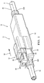
- Fig. 1 illustrates an non-limiting example of a connector assembly 10, in this case an electrical connector assembly 10 configured to connect cables carrying signals according to the Universal Serial Bus (USB) 3.0 standard.
- USB 3.0 electrical terminals have overlapping contact points that may be particularly sensitive to longitudinal location relative to each other. Therefore, reducing the longitudinal tolerance between the terminals is beneficial to the performance of the connector assembly 10.
- the illustrated connector assembly 10 is configured for application in an automotive environment.
- the connector assembly 10 includes a first connector 12 holding electrical terminals (not shown due to perspective) for a first wire cable 14.
- a second connector 16 holds the corresponding mating terminals 18 for a second wire cable 20.
- the first connector 12 is configured to be received within the second connector 16.
- the first and second connectors 12, 16 as shown also include locking features to secure the first and second connectors 12, 16 together once the first and second connectors 12, 16 are fully mated.
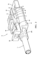
- Fig. 2 illustrates the first connector 12 that includes a first connector body 22, terminals (not shown due to perspective), a terminal shield 24, a connector position assurance (CPA) device 26, and a wire strain relief device 28A.
- the first connector body 22 is formed of a dielectric material, for example a polymeric material such as polyamide (PA, commonly known as NYLON), polypropylene (PP), or polybutylene terephthalate (PBT).
- PA polyamide
- PP polypropylene
- PBT polybutylene terephthalate
- a mesial location is closer to the longitudinal axis X and a distal location is farther from the longitudinal axis X.
- lateral describes a direction generally perpendicular to the longitudinal axis X.
- a forward direction is in the insertion direction 30 of the first connector 12 into the second connector 16 along the longitudinal axis X and a rearward direction is opposite the insertion direction 30.
- a rearward location on the first connector 12 is nearer the first wire cable 14 and on the second connector 16 is nearer the second wire cable 20 and a forward location is nearer the opposite end of the connector along the longitudinal axis X.
- the first connector body 22 defines a channel 32 near a distal edge 34 of the first connector body 22.
- the channel 32 has a longitudinally-oriented and substantially inflexible fixed inner wall 36 and a longitudinally-oriented flexible beam 38 located opposite and generally parallel to the fixed inner wall 36 when the flexible beam 38 is in a relaxed state.
- the channel 32 also has a longitudinally-oriented and substantially inflexible fixed upper wall 40 and substantially inflexible fixed lower wall 42.
- the first connector body 22 also includes a second mirror imaged channel 32 on the opposite side of the connector.
- the flexible beam 38 is integrally formed with the first connector body 22 and is formed from the same material as the first connector body 22. The longitudinal ends 44 of the flexible beam 38 are fixed to the first connector body 22.
- a distal surface 46 of the flexible beam 38 defines a first protrusion 48 that has a first inclined surface 50 on the rearward side of the first protrusion 48.
- Alternative embodiments of the flexible beam 38 may be envisioned wherein the flexible beam 38 is not integrally formed or is formed of a different material.
- the flexible beam may be a cantilevered beam wherein one longitudinal end is fixed to the first connector body and the other longitudinal end is a free end unattached to the first connector body.
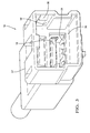
- Fig. 3 illustrates the second connector 16 that includes a second connector body 52, mating terminals 18, a mating terminal shield 54, and a wire strain relief device 28B (see Fig 1 ).
- the second connector body 52 is also formed of a dielectric material which may or may not be the same material used to form the first connector body 22.
- the second connector body 52 defines a shroud cavity 56 that is configured to receive the first connector body 22.
- a mesial surface 58 of the cavity 56 defines a second protrusion 60 having a second inclined surface 62 on the rearward side of the second protrusion 60.
- the second connector body 52 also includes another mirror imaged second protrusion 60 on the opposite mesial surface of the cavity 56 (not shown due to perspective).
- the second inclined surface 62 is configured to abut and engage the first inclined surface 50 of the first protrusion 48 defined by the flexible beam 38 when the first connector body 22 is fully inserted within the cavity 56 of the second connector body 52.
- the first inclined surface 50 defines a first acute angle ⁇ with respect to the distal surface 46 of the flexible beam 38
- the second inclined surface 62 defines a second acute angle ⁇ with respect to the mesial surface 58 of the cavity 56. According to the illustrated example, an angular measurement of the first acute angle ⁇ is equal to an angular measurement of the second acute angle ⁇ .
- the CPA device 26 defines a pair of longitudinal members 64 that are inserted within each of the channels.
- the longitudinal members 64 When CPA device 26 is moved from a disengaged position 66 to an engaged position 68, the longitudinal members 64 are moved from a rearward position to a forward position within the channel 32.
- the longitudinal members 64 cause the flexible beams to flex laterally and move the first inclined surfaces 50 with respect to the second inclined surfaces 62 sufficient to generate a longitudinal reaction force F in the forward or insertion direction 30 of the first connector body 22 between the first and second inclined surfaces 50, 62 and thus between the first and second connector bodies 22, 52.
- a mesial beam surface 70 of the flexible beam 38 defines a third protrusion 72 having a third inclined surface 74.
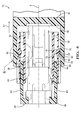
- the first connector body 22 is fully inserted into the cavity 56 of the second connector body 52.
- a fourth inclined surface 76 on a forward edge of the first protrusion 48 engages a fifth inclined surface 78 on a forward edge of the second protrusion 60.
- the fourth and fifth inclined surfaces 76, 78 cause the flexible beam 38 to deflect laterally in a mesial or inward direction allowing the first protrusion 48 to move over and past the second protrusion 60, thereby putting the first and second inclined surfaces 50, 62 into contact.
- the longitudinal members 64 when the longitudinal members 64 are inserted into the channel 32, the longitudinal members 64 engage the fixed inner wall 36 and the free end 80 of the longitudinal member 64 contacts the third inclined surface 74. As the free end 80 slides along the third inclined surface 74, the flexible beam 38 is flexed laterally on a distal or outward direction. The lateral movement of the flexible beam 38 causes lateral movement of the first inclined surface 50 with respect to the second inclined surface 62 which produces the reaction force F along the longitudinal axis in the insertion direction 30.
- the reaction force F generated can be tuned by the angles ⁇ , ⁇ of the first and second inclined surfaces 50, 62 and the height H of the third protrusion 72.
- This reaction force F causes the forward end 82 of the first connector body 22 to snugly engage the rearward end 84 of the connector body.
- This engagement fixedly locates the first connector body 22 relative to the second connector body 52, thereby reducing vibration between the first and second connector bodies 22, 52 as well as reducing longitudinal locational tolerance between the electrical terminals in the first connector body 22 and the mating terminals 18 in the second connector body 52.
- the engagement of the first and second protrusions 48, 60 may also reduce lateral locational tolerance between the electrical terminals in the first connector body 22 and the mating terminals 18 in the second connector body 52.
- the first connector body 22 includes a flexible latching arm 86 having a lock notch (not shown).
- the second connector body 52 defines an inwardly extending lock nib (not shown) that is configured to engage the lock notch, thereby providing a primary lock securing the second connector body 52 within the cavity 56 of the first connector body 22.
- the CPA device 26 is configured to prevent inadvertent disengagement of the lock notch from the lock nib by forming a wedge between the latching arm 86 and the first connector body 22.
- the lock notch may be disengaged from the lock nib by pressing on a free end of the latching arm 86 when the CPA device 26 is in the disengaged position 66 as shown in Fig.
- the longitudinal member 64 which is attached to the CPA device 26 is not engaged with the first inclined surface 50 when the CPA device 26 is in the disengaged position 66 as shown in Fig. 4 and the longitudinal member 64 is engaged with the first inclined surface 50 when the CPA device 26 is in the engaged position 68 as shown in Fig. 5 .
- the engagement of the first and second inclined surfaces 50, 62 of the first and second protrusions 48, 60 when the CPA device 26 is in the engaged position 68 may serve as a secondary lock securing the second connector body 52 within the cavity 56 of the first connector body 22.
- Alternative embodiments of the connector assembly may be envisioned in which the flexible latching arm, lock notch, and lock nib are eliminated and the first and second protrusions provides the primary lock.
- the forward end 88 of the first inclined surface 50 is laterally aligned with the forward end 90 of the third inclined surface 74.
- Fig. 7 illustrates an alternative embodiment of the connector assembly 10' with the CPA device 26' in the disengaged position 66'.
- a distal wall surface of the fixed inner wall 36' defines a third protrusion 72' having a third inclined surface 74' and the mesial surface 58'of the flexible beam 38' does not define a protrusion.
- the free end 80' of the longitudinal member 64' contacts the third inclined surface 74' causing the longitudinal member 64' to flex laterally in a distal or outward direction and contact the flexible beam 38', thereby causing the flexible beam 38' to flex laterally.
- the lateral movement of the flexible beam 38' causes lateral movement of the first inclined surface 50' with respect to the second inclined surface 62' which produces a reaction force F' along the longitudinal axis X' in the insertion direction 30'.
- a distal surface of the member defines a third protrusion that causes the flexible beam to flex outwardly when the CPA device is moved to the engaged position.
- the third protrusion may include a third inclined surface that engages a second protrusion on the mesial surface of the flexible beam or the third protrusion may be the sole means for causing the outward flexation of the flexible beam.
- the examples presented herein are directed to electrical connector assemblies, however other embodiments of the connector assembly may be envisioned that are adapted for use with optical cables or hybrid connectors including both electrical and optical cable connections. Yet other embodiments of the connector assembly may be envisioned that are configured to interconnect pneumatic or hydraulic lines.
- the reaction force generated by the first and second protrusions may beneficially provide a sealing force to seals interconnecting pneumatic or hydraulic lines.
- the connector assembly 10, 10' has a fixed inclined surface 62 and a movable inclined surface 50 that generates a reaction force F to snugly engage a pair of first and second connectors 12, 16 that can limit the amount of vibrational movement between the first and second connectors 12, 16 and longitudinally locate the first and second connectors 12, 16 relative to each other.
- This is particularly beneficial for connector assemblies 10, 10' having terminals with overlapping contact points that may be particularly sensitive to longitudinal location relative to each other, such as a USB 3.0 connector assembly.
- the fixed and moveable inclined surfaces 50, 62 may further laterally locate the first and second connectors 12, 16 relative to each other.
- the fixed and moveable inclined surfaces 50, 62 also provide a primary or secondary lock feature to secure the first and second connectors 12, 16 to one another.
Landscapes
- Connector Housings Or Holding Contact Members (AREA)
- Details Of Connecting Devices For Male And Female Coupling (AREA)
Abstract
Description
- The invention relates to a connector assemblies, particularly a connector assembly configured to dampen vibration between mating connector bodies in the connector assembly and assure positional relationships between mating terminals.
- Sealed connector assemblies include compliant seals between the mating connector bodies to stop the entry of environmental contaminants, such as, dust, dirt, water or other fluids into the connector bodies of the connector assembly. These compliant seals also serve to reduce the relative motion between the connector bodies, and hence the electrical terminals within the connector bodies caused by vibration within a vehicle. This relative motion between terminals can cause undesirable intermittent connections or fretting corrosion. Unsealed connection assemblies do not have compliant seals and typically rely on connector fit/clearances to reduce movement between the connector bodies and can typically only function in lower vibration environments, such as those associated with a vehicle passenger compartment. Sealed connectors may be used in higher vibration environments where their resistance to environmental contaminants is not required; however, sealed connector assemblies are typically more expensive than equivalent unsealed connector assemblies. Therefore, it is desirable to have an unsealed connector assembly that can withstand higher vibration environments.
- In addition, as electrical connector assemblies are miniaturized, the contact surface between mating electrical terminals in the connector assembly is smaller making alignment, especially longitudinal alignment between the terminals, more critical. Therefore, it is desirable to have a connector assembly that can help to assure longitudinal location of mating terminals relative to one another.
- The subject matter discussed in the background section should not be assumed to be prior art merely as a result of its mention in the background section. Similarly, a problem mentioned in the background section or associated with the subject matter of the background section should not be assumed to have been previously recognized in the prior art. The subject matter in the background section merely represents different approaches, which in and of themselves may also be inventions.
- In accordance with an embodiment of the invention, a connection assembly is provided. The connector assembly includes a first connector body that defines a channel between a longitudinally-oriented fixed wall and a longitudinally-oriented flexible beam. The flexible beam is located opposite and generally parallel to the fixed wall when in a relaxed state. A distal beam surface of the flexible beam defines a first protrusion having a first inclined surface. The connector assembly also includes a second connector body that defines a cavity which is configured to receive the first connector body. A mesial surface inside of the cavity defines a second protrusion having a second inclined surface that is configured to abut and engage the first inclined surface of the flexible beam when the first connector body is disposed within the cavity of the second connector body. The connector assembly further includes a member that is configured to be inserted within the channel. When the member is inserted into the channel, it causes the flexible beam to flex laterally and move the first inclined surface with respect to the second inclined surface sufficient to generate a longitudinal force between the first and second inclined surfaces.
- According to one particular embodiment of the invention, a mesial beam surface of the flexible beam defines a third protrusion having a third inclined surface. When the member is inserted into the channel, the member engages the third inclined surface and causes the flexible beam to flex laterally and move the first inclined surface with respect to the second inclined surface. The first inclined surface defines a first acute angle with respect to the distal beam surface, and the second inclined surface defines a second acute angle with respect to the mesial cavity surface. An angular measurement of the first acute angle is equal to an angular measurement of the second acute angle. Each longitudinal end of the flexible beam is fixed to the first connector body. The first connector body further comprises an electrical terminal and the second connector body further comprises a corresponding mating electrical terminal. The first connector body defines a flexible latching arm configured to secure the first connector body within the cavity of the second connector body. The member is characterized as a longitudinal member and is defined by a connector position assurance device. The latching arm may be disengaged to release the first connector body from the second connector body by pressing on a free end of the latching arm when the connector position assurance device is in a disengaged position and the latching arm is inhibited from disengagement when the connector position assurance device is in an engaged position. The longitudinal member is not engaged with the first inclined surface when the connector position assurance device is in the disengaged position and the longitudinal member is engaged with the first inclined surface when the connector position assurance device is in the engaged position.
- According to another embodiment of the invention, a distal wall surface of the fixed wall defines the third protrusion having a third inclined surface. When the member is inserted into the channel, the member engages the third inclined surface causing the member to flex laterally and contact the flexible beam, thereby causing the flexible beam to also flex laterally and move the first inclined surface with respect to the second inclined surface.
- The present invention will now be described, by way of example with reference to the accompanying drawings, in which:
-
Fig. 1 is a perspective view of a connector assembly according to one embodiment; -
Fig. 2 is a perspective view of a first connector body of the connector assembly ofFig. 1 according to one embodiment; -
Fig. 3 is a perspective view of a second connector body of the connector assembly ofFig. 1 according to one embodiment; -
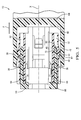
Fig. 4 is a partially cut-away top view of the connector assembly ofFig. 1 with a connector position assurance device in a disengaged position according to one embodiment; -
Fig. 5 is a partially cut-away top view of the connector assembly ofFig. 1 with a connector position assurance device in an engaged position according to one embodiment; -
Fig. 6 is a close-up top view of a first, second, and third protrusion of the connector assembly ofFig. 1 according to one embodiment; -
Fig. 7 is a partially cut-away top view of the connector assembly ofFig. 1 with a connector position assurance device in a disengaged position according to another embodiment. - The connector assembly described herein is designed to connect first connector body to a mating second connector body to provide a tight longitudinal fit. As the first connector is inserted into a shrouded cavity of the second connector, an inclined surface protruding from an outside edge of a flexible beam mounted to the first connector engages a corresponding inclined surface protruding from an inside wall of the cavity. Once the inclined surfaces are engaged, a member is inserted into a cavity behind the flexible beam causing the beam to flex laterally outward. This lateral movement of the flexible beam causes the inclined surfaces to move relative to each other, thereby generating a force in the longitudinal direction that may cause the ends of the first and second connector bodies to move so that they are in intimate contact with each other. This intimate contact reduces the amount of relative vibration between the connectors and hence electrical terminals within the connectors. It also provides longitudinal positional assurance of the connectors and hence electrical terminals within the connectors.
-
Fig. 1 illustrates an non-limiting example of aconnector assembly 10, in this case anelectrical connector assembly 10 configured to connect cables carrying signals according to the Universal Serial Bus (USB) 3.0 standard. USB 3.0 electrical terminals have overlapping contact points that may be particularly sensitive to longitudinal location relative to each other. Therefore, reducing the longitudinal tolerance between the terminals is beneficial to the performance of theconnector assembly 10. The illustratedconnector assembly 10 is configured for application in an automotive environment. Theconnector assembly 10 includes afirst connector 12 holding electrical terminals (not shown due to perspective) for afirst wire cable 14. Asecond connector 16 holds thecorresponding mating terminals 18 for asecond wire cable 20. Thefirst connector 12 is configured to be received within thesecond connector 16. The first andsecond connectors second connectors second connectors -
Fig. 2 illustrates thefirst connector 12 that includes afirst connector body 22, terminals (not shown due to perspective), aterminal shield 24, a connector position assurance (CPA)device 26, and a wirestrain relief device 28A. Thefirst connector body 22 is formed of a dielectric material, for example a polymeric material such as polyamide (PA, commonly known as NYLON), polypropylene (PP), or polybutylene terephthalate (PBT). - As used herein, a mesial location is closer to the longitudinal axis X and a distal location is farther from the longitudinal axis X. As used herein, lateral describes a direction generally perpendicular to the longitudinal axis X. A forward direction is in the
insertion direction 30 of thefirst connector 12 into thesecond connector 16 along the longitudinal axis X and a rearward direction is opposite theinsertion direction 30. A rearward location on thefirst connector 12 is nearer thefirst wire cable 14 and on thesecond connector 16 is nearer thesecond wire cable 20 and a forward location is nearer the opposite end of the connector along the longitudinal axis X. - The
first connector body 22 defines achannel 32 near adistal edge 34 of thefirst connector body 22. Thechannel 32 has a longitudinally-oriented and substantially inflexible fixedinner wall 36 and a longitudinally-orientedflexible beam 38 located opposite and generally parallel to the fixedinner wall 36 when theflexible beam 38 is in a relaxed state. Thechannel 32 also has a longitudinally-oriented and substantially inflexible fixedupper wall 40 and substantially inflexible fixedlower wall 42. Thefirst connector body 22 also includes a second mirror imagedchannel 32 on the opposite side of the connector. Theflexible beam 38 is integrally formed with thefirst connector body 22 and is formed from the same material as thefirst connector body 22. The longitudinal ends 44 of theflexible beam 38 are fixed to thefirst connector body 22. Adistal surface 46 of theflexible beam 38 defines afirst protrusion 48 that has a firstinclined surface 50 on the rearward side of thefirst protrusion 48. Alternative embodiments of theflexible beam 38 may be envisioned wherein theflexible beam 38 is not integrally formed or is formed of a different material. In other alternative embodiments, the flexible beam may be a cantilevered beam wherein one longitudinal end is fixed to the first connector body and the other longitudinal end is a free end unattached to the first connector body. -
Fig. 3 illustrates thesecond connector 16 that includes asecond connector body 52,mating terminals 18, amating terminal shield 54, and a wirestrain relief device 28B (seeFig 1 ). Thesecond connector body 52 is also formed of a dielectric material which may or may not be the same material used to form thefirst connector body 22. Thesecond connector body 52 defines ashroud cavity 56 that is configured to receive thefirst connector body 22. Amesial surface 58 of thecavity 56 defines asecond protrusion 60 having a secondinclined surface 62 on the rearward side of thesecond protrusion 60. Thesecond connector body 52 also includes another mirror imagedsecond protrusion 60 on the opposite mesial surface of the cavity 56 (not shown due to perspective). The secondinclined surface 62 is configured to abut and engage the firstinclined surface 50 of thefirst protrusion 48 defined by theflexible beam 38 when thefirst connector body 22 is fully inserted within thecavity 56 of thesecond connector body 52. The firstinclined surface 50 defines a first acute angle α with respect to thedistal surface 46 of theflexible beam 38, and the secondinclined surface 62 defines a second acute angle β with respect to themesial surface 58 of thecavity 56. According to the illustrated example, an angular measurement of the first acute angle α is equal to an angular measurement of the second acute angle β. - Referring again to
Fig. 2 , theCPA device 26 defines a pair oflongitudinal members 64 that are inserted within each of the channels. WhenCPA device 26 is moved from adisengaged position 66 to an engagedposition 68, thelongitudinal members 64 are moved from a rearward position to a forward position within thechannel 32. Thelongitudinal members 64 cause the flexible beams to flex laterally and move the firstinclined surfaces 50 with respect to the secondinclined surfaces 62 sufficient to generate a longitudinal reaction force F in the forward orinsertion direction 30 of thefirst connector body 22 between the first and secondinclined surfaces second connector bodies - According to the illustrated example shown in
Fig. 2 , amesial beam surface 70 of theflexible beam 38 defines athird protrusion 72 having a thirdinclined surface 74. - As illustrated in
Fig 4 , thefirst connector body 22 is fully inserted into thecavity 56 of thesecond connector body 52. As thefirst connector body 22 is inserted into thecavity 56 in the forward orinsertion direction 30, a fourthinclined surface 76 on a forward edge of thefirst protrusion 48 engages a fifthinclined surface 78 on a forward edge of thesecond protrusion 60. As thefirst connector body 22 is inserted, the fourth and fifthinclined surfaces flexible beam 38 to deflect laterally in a mesial or inward direction allowing thefirst protrusion 48 to move over and past thesecond protrusion 60, thereby putting the first and secondinclined surfaces - As shown in
Fig. 5 , when thelongitudinal members 64 are inserted into thechannel 32, thelongitudinal members 64 engage the fixedinner wall 36 and thefree end 80 of thelongitudinal member 64 contacts the thirdinclined surface 74. As thefree end 80 slides along the thirdinclined surface 74, theflexible beam 38 is flexed laterally on a distal or outward direction. The lateral movement of theflexible beam 38 causes lateral movement of the firstinclined surface 50 with respect to the secondinclined surface 62 which produces the reaction force F along the longitudinal axis in theinsertion direction 30. The reaction force F generated can be tuned by the angles α, β of the first and secondinclined surfaces third protrusion 72. - This reaction force F causes the
forward end 82 of thefirst connector body 22 to snugly engage therearward end 84 of the connector body. This engagement fixedly locates thefirst connector body 22 relative to thesecond connector body 52, thereby reducing vibration between the first andsecond connector bodies first connector body 22 and themating terminals 18 in thesecond connector body 52. The engagement of the first andsecond protrusions first connector body 22 and themating terminals 18 in thesecond connector body 52. - The
first connector body 22 includes aflexible latching arm 86 having a lock notch (not shown). Thesecond connector body 52 defines an inwardly extending lock nib (not shown) that is configured to engage the lock notch, thereby providing a primary lock securing thesecond connector body 52 within thecavity 56 of thefirst connector body 22. TheCPA device 26 is configured to prevent inadvertent disengagement of the lock notch from the lock nib by forming a wedge between the latchingarm 86 and thefirst connector body 22. The lock notch may be disengaged from the lock nib by pressing on a free end of the latchingarm 86 when theCPA device 26 is in thedisengaged position 66 as shown inFig. 4 and the lock notch is inhibited from disengaging the lock nib when theCPA device 26 is in the engagedposition 68 as shown inFig. 5 . Thelongitudinal member 64 which is attached to theCPA device 26 is not engaged with the firstinclined surface 50 when theCPA device 26 is in thedisengaged position 66 as shown inFig. 4 and thelongitudinal member 64 is engaged with the firstinclined surface 50 when theCPA device 26 is in the engagedposition 68 as shown inFig. 5 . The engagement of the first and secondinclined surfaces second protrusions CPA device 26 is in the engagedposition 68 may serve as a secondary lock securing thesecond connector body 52 within thecavity 56 of thefirst connector body 22. Alternative embodiments of the connector assembly may be envisioned in which the flexible latching arm, lock notch, and lock nib are eliminated and the first and second protrusions provides the primary lock. - As shown in
Fig. 6 , theforward end 88 of the firstinclined surface 50 is laterally aligned with theforward end 90 of the thirdinclined surface 74. -
Fig. 7 illustrates an alternative embodiment of the connector assembly 10' with the CPA device 26' in the disengaged position 66'. According to this alternative embodiment, rather than the third protrusion being defined by the flexible beam, a distal wall surface of the fixed inner wall 36' defines a third protrusion 72' having a third inclined surface 74' and the mesial surface 58'of the flexible beam 38' does not define a protrusion. When the longitudinal member 64' is inserted into the channel 32' as the CPA device 26' is moved from the disengaged position 66', the free end 80' of the longitudinal member 64' contacts the third inclined surface 74' causing the longitudinal member 64' to flex laterally in a distal or outward direction and contact the flexible beam 38', thereby causing the flexible beam 38' to flex laterally. The lateral movement of the flexible beam 38' causes lateral movement of the first inclined surface 50' with respect to the second inclined surface 62' which produces a reaction force F' along the longitudinal axis X' in the insertion direction 30'. - Yet other alternative embodiments of the connector assembly may be envisioned in which a distal surface of the member defines a third protrusion that causes the flexible beam to flex outwardly when the CPA device is moved to the engaged position. The third protrusion may include a third inclined surface that engages a second protrusion on the mesial surface of the flexible beam or the third protrusion may be the sole means for causing the outward flexation of the flexible beam.
- The examples presented herein are directed to electrical connector assemblies, however other embodiments of the connector assembly may be envisioned that are adapted for use with optical cables or hybrid connectors including both electrical and optical cable connections. Yet other embodiments of the connector assembly may be envisioned that are configured to interconnect pneumatic or hydraulic lines. The reaction force generated by the first and second protrusions may beneficially provide a sealing force to seals interconnecting pneumatic or hydraulic lines.
- Accordingly a
connector assembly 10, 10' is provided. Theconnector assembly 10, 10' has a fixedinclined surface 62 and a movableinclined surface 50 that generates a reaction force F to snugly engage a pair of first andsecond connectors second connectors second connectors connector assemblies 10, 10' having terminals with overlapping contact points that may be particularly sensitive to longitudinal location relative to each other, such as a USB 3.0 connector assembly. The fixed and moveableinclined surfaces second connectors inclined surfaces second connectors - While this invention has been described in terms of the preferred embodiments thereof, it is not intended to be so limited, but rather only to the extent set forth in the claims that follow. Moreover, the use of the terms first, second, etc. does not denote any order of importance, but rather the terms first, second, etc. are used to distinguish one element from another. Furthermore, the use of the terms a, an, etc. do not denote a limitation of quantity, but rather denote the presence of at least one of the referenced items.
Claims (15)
- Connector assembly (10), comprising:a first connector body (22) defining a channel (32) between a longitudinally-oriented fixed wall and a longitudinally-oriented flexible beam (38) located opposite and generally parallel to the fixed wall when in a relaxed state, wherein a distal beam surface (46) of the flexible beam (38) defines a first protrusion (48) having a first inclined surface (50);a second connector body (52) defining a cavity (56) configured to receive the first connector body (22), wherein a mesial cavity (56) surface of the cavity (56) defines a second protrusion (60) having a second inclined surface (62) that is configured to abut and engage the first inclined surface (50) when the first connector body (22) is disposed within the cavity (56) of the second connector body (52); anda member (64) configured to be inserted within the channel (32) and, when inserted into the channel (32), causes the flexible beam (38) to flex laterally and move the first inclined surface (50) with respect to the second inclined surface sufficient to generate a longitudinal force (F) between the first and second inclined surfaces (50, 62).
- Connector assembly (10) according to claim 1, wherein a mesial beam surface (70) of the flexible beam (38) defines a third protrusion (72) having a third inclined surface (74) and when inserted into the channel (32), the member (64) engages the third inclined surface (74) causing the flexible beam (38) to flex laterally and move the first inclined surface (50) with respect to the second inclined surface (62).
- Connector assembly (10) according to any of the preceding claims, wherein the first inclined surface (50) defines a first acute angle (α) with respect to the distal beam surface (46), and the second inclined surface (62) defines a second acute angle (β) with respect to the mesial cavity surface (58).
- Connector assembly (10) according to claim 3, wherein an angular measurement of the first acute angle (α) is equal to an angular measurement of the second acute angle (β).
- Connector assembly (10) according to any of the preceding claims, wherein each longitudinal end of the flexible beam (38) is fixed to the first connector body (22).
- Connector assembly (10) according to any of the preceding claims, wherein the first connector body (22) further comprises an electrical terminal and the second connector body (52) further comprises a corresponding mating electrical terminal (18).
- Connector assembly (10) according to any of the preceding claims, wherein the first connector body (22) defines a flexible latching arm (86) configured to secure the first connector body (22) within the cavity (56) of the second connector body (52).
- Connector assembly (10) according to any of the preceding claims, wherein the member (64) is characterized as a longitudinal member (64) and is defined by a connector position assurance device (26).
- Connector assembly (10) according to any of the preceding claims, wherein the latching arm (86) may be disengaged when the connector position assurance device (26) is in a disengaged position (66) and wherein the latching arm (86) is inhibited from disengaging when the connector position assurance device (26) is in an engaged position (68).
- Connector assembly (10) according to any of the preceding claims, wherein the longitudinal member (64) is not engaged with the first inclined surface (50) when the connector position assurance device (26) is in the disengaged position (66) and the longitudinal member (64) is engaged with the first inclined surface (50) when the connector position assurance device (26) is in the engaged position (68).
- Connector assembly (10') according to claim 1, wherein a distal wall surface of the fixed wall defines a third protrusion (72') having a third inclined surface (74') and when inserted into the channel (32'), the member (64') engages the third inclined surface (74') causing the member (64)' to flex laterally and contact the flexible beam (38'), thereby causing the flexible beam (38') to flex laterally and move the first inclined surface (50') with respect to the second inclined surface (62').
- Connector assembly (10') according to claim 11, wherein the first inclined surface (50') defines a first acute angle (α') with respect to the distal beam surface (46), and the second inclined surface (62') defines a second acute angle (β') with respect to the mesial cavity surface (58') and wherein an angular measurement of the first acute angle (α') is equal to an angular measurement of the second acute angle (β').
- Connector assembly (10') according to claim 11 or 12, wherein each longitudinal end of the flexible beam (38') is fixed to the first connector body (22').
- Connector assembly (10') according to any of the claims 11 through 13, wherein the first connector body (22') further comprises an electrical terminal and the second connector body (52') further comprises a corresponding mating electrical terminal (18).
- Connector assembly (10') according to any of the claims 11 through 14, wherein the member (64') is characterized as a longitudinal member (64') and is defined by a connector position assurance device (26').
Applications Claiming Priority (1)
| Application Number | Priority Date | Filing Date | Title |
|---|---|---|---|
| US14/735,406 US9350116B1 (en) | 2015-06-10 | 2015-06-10 | Connector system with connector position assurance device |
Publications (2)
| Publication Number | Publication Date |
|---|---|
| EP3104468A1 true EP3104468A1 (en) | 2016-12-14 |
| EP3104468B1 EP3104468B1 (en) | 2023-05-31 |
Family
ID=55969818
Family Applications (1)
| Application Number | Title | Priority Date | Filing Date |
|---|---|---|---|
| EP16173156.7A Active EP3104468B1 (en) | 2015-06-10 | 2016-06-06 | Connector assembly with connector position assurance device |
Country Status (4)
| Country | Link |
|---|---|
| US (1) | US9350116B1 (en) |
| EP (1) | EP3104468B1 (en) |
| KR (1) | KR101796383B1 (en) |
| CN (1) | CN106252919B (en) |
Families Citing this family (20)
| Publication number | Priority date | Publication date | Assignee | Title |
|---|---|---|---|---|
| JP6569131B2 (en) * | 2016-04-26 | 2019-09-04 | 株式会社オートネットワーク技術研究所 | Electrical connection device having fitting detection function |
| DE102016212923B4 (en) * | 2016-07-14 | 2025-02-06 | Te Connectivity Germany Gmbh | Vibration-damping plug with a vibration damper and assembly comprising this plug and a mating plug |
| JP6417370B2 (en) * | 2016-07-29 | 2018-11-07 | 矢崎総業株式会社 | connector |
| JP6417369B2 (en) * | 2016-07-29 | 2018-11-07 | 矢崎総業株式会社 | connector |
| JP1584769S (en) * | 2016-12-13 | 2017-08-28 | ||
| JP1584768S (en) * | 2016-12-13 | 2017-08-28 | ||
| JP6560273B2 (en) | 2017-02-06 | 2019-08-14 | 矢崎総業株式会社 | Mating connector |
| JP2020047365A (en) * | 2018-09-14 | 2020-03-26 | 住友電装株式会社 | connector |
| US11183793B2 (en) | 2018-10-08 | 2021-11-23 | Aptiv Technologies Limited | Connector system with a terminal retaining device having a reverse hinged lock feature |
| FR3098028B1 (en) * | 2019-06-28 | 2025-04-04 | Aptiv Tech Ltd | Connector assembly with locking device |
| US10826220B1 (en) | 2019-09-25 | 2020-11-03 | Lear Corporation | Electrical connector having electrical terminal servicing feature |
| CN211743556U (en) * | 2020-03-06 | 2020-10-23 | 东莞富强电子有限公司 | Plug electric connector |
| EP3896800B1 (en) * | 2020-04-16 | 2025-12-03 | Connecteurs Electriques Deutsch | Electrical connector comprising a securing tab |
| US11594838B2 (en) * | 2020-04-28 | 2023-02-28 | Foxconn (Kunshan) Computer Connector Co., Ltd. | Connector assembly with connector position assurance |
| DE102020207331A1 (en) * | 2020-06-12 | 2021-12-16 | Aptiv Technologies Limited | CONNECTOR HOUSING AND CONNECTOR ARRANGEMENT FOR SEALED RING CONNECTIONS |
| US12107367B2 (en) * | 2020-09-25 | 2024-10-01 | Ncr Corporation | System and apparatuses for communication port cord retention |
| US11309660B1 (en) * | 2020-10-21 | 2022-04-19 | Aptiv Technologies Limited | Anti-vibration stabilized connected system with self-rejecting ergonomic feedback mechanism |
| WO2023034396A1 (en) | 2021-09-01 | 2023-03-09 | Fci Usa Llc | High speed, ruggedized connector |
| CN114709668A (en) | 2021-12-17 | 2022-07-05 | 安波福连接器系统(南通)有限公司 | Connector position holding device and connector assembly |
| CN217882141U (en) * | 2022-06-08 | 2022-11-22 | 东莞富强电子有限公司 | Electric connector set |
Citations (2)
| Publication number | Priority date | Publication date | Assignee | Title |
|---|---|---|---|---|
| DE10202920A1 (en) * | 2002-01-25 | 2003-08-21 | Tyco Electronics Amp Gmbh | Electrical pluggable connector e.g. for motor vehicle passenger restraint system, has contact springs electrically joined to electrical cable for lockably receiving plug |
| US8968021B1 (en) * | 2013-12-11 | 2015-03-03 | JAE Oregon, Inc. | Self-rejecting automotive harness connector |
Family Cites Families (14)
| Publication number | Priority date | Publication date | Assignee | Title |
|---|---|---|---|---|
| DE19549519B4 (en) * | 1995-01-14 | 2005-05-19 | Amphenol-Tuchel Electronics Gmbh | Electrical connector |
| US6106340A (en) * | 1998-04-30 | 2000-08-22 | The Whitaker Corporation | Electrical connector with deflectable secondary |
| US6261115B1 (en) * | 1999-06-11 | 2001-07-17 | Tyco Electronics Logistics Ag | Connector module |
| DE10035726B4 (en) * | 2000-01-25 | 2004-03-04 | Audi Ag | contact support |
| US6435895B1 (en) | 2001-04-27 | 2002-08-20 | Delphi Technologies, Inc. | Connector position assurance device |
| US6857892B2 (en) | 2003-06-05 | 2005-02-22 | Fci Americas Technology, Inc. | Electrical connector with connector position assurance member |
| DE602004032354D1 (en) * | 2003-06-18 | 2011-06-01 | Framatome Connectors Int | ELECTRICAL CONNECTOR |
| FR2875957A1 (en) * | 2004-09-29 | 2006-03-31 | Fci Sa | DEVICE FOR LATCHING CONNECTOR ELEMENTS AND CONNECTOR COMPRISING SAME |
| JP4606263B2 (en) * | 2005-07-19 | 2011-01-05 | 矢崎総業株式会社 | Double locking connector |
| US7470138B1 (en) * | 2007-07-18 | 2008-12-30 | J.S.T. Corporation | Connector position assurance device and connector assembly apparatus incorporating the same |
| US8092245B2 (en) | 2008-10-14 | 2012-01-10 | Delphi Technologies, Inc. | Electrical connector assembly |
| US8137142B1 (en) * | 2011-09-22 | 2012-03-20 | Yazaki North America, Inc. | Connector assembly |
| CN103515744B (en) * | 2012-06-27 | 2017-05-03 | 比亚迪汽车有限公司 | Electrical connector |
| US9160095B2 (en) | 2013-02-28 | 2015-10-13 | Yazaki North America, Inc. | Connector assembly with connector position assurance stabilizer |
-
2015
- 2015-06-10 US US14/735,406 patent/US9350116B1/en active Active
-
2016
- 2016-06-06 EP EP16173156.7A patent/EP3104468B1/en active Active
- 2016-06-07 KR KR1020160070151A patent/KR101796383B1/en active Active
- 2016-06-13 CN CN201610413993.4A patent/CN106252919B/en active Active
Patent Citations (2)
| Publication number | Priority date | Publication date | Assignee | Title |
|---|---|---|---|---|
| DE10202920A1 (en) * | 2002-01-25 | 2003-08-21 | Tyco Electronics Amp Gmbh | Electrical pluggable connector e.g. for motor vehicle passenger restraint system, has contact springs electrically joined to electrical cable for lockably receiving plug |
| US8968021B1 (en) * | 2013-12-11 | 2015-03-03 | JAE Oregon, Inc. | Self-rejecting automotive harness connector |
Also Published As
| Publication number | Publication date |
|---|---|
| KR20160145493A (en) | 2016-12-20 |
| KR101796383B1 (en) | 2017-11-09 |
| CN106252919B (en) | 2019-04-12 |
| EP3104468B1 (en) | 2023-05-31 |
| CN106252919A (en) | 2016-12-21 |
| US9350116B1 (en) | 2016-05-24 |
Similar Documents
| Publication | Publication Date | Title |
|---|---|---|
| EP3104468B1 (en) | Connector assembly with connector position assurance device | |
| EP2937947B1 (en) | Vibration resistant connector system with connector position assurance device | |
| KR101973894B1 (en) | Electrical connector with a terminal position assurance device | |
| US9270055B2 (en) | Connector with vibratory connection feedback | |
| US9455523B1 (en) | Right angle connection assembly | |
| US6840789B2 (en) | Connector and a method of assembling it | |
| CN110323589B (en) | Bus bar assembly, terminal block, and vehicle device | |
| CN111903006B (en) | Connector with a locking member | |
| US9300085B2 (en) | Electrical wiring assembly and vibration resistant electrical connector for same | |
| CN103368009B (en) | Connector | |
| US10903604B2 (en) | Connector with a housing that restricts excessive deflection of the lock arm | |
| JP2002008764A (en) | connector | |
| US20190326702A1 (en) | Connector | |
| JP2025070012A (en) | connector | |
| US20180026390A1 (en) | Connector | |
| US11128090B2 (en) | Connector with lock arm having a forwardly open entrance space that receives tip of mating connector to shorten front-rear dimension after connection | |
| US20240313459A1 (en) | Connector | |
| JP6224041B2 (en) | Connector waterproof structure | |
| US20230102502A1 (en) | Connector | |
| US12562520B2 (en) | Connector assembly with terminal position assurance and blocking feature | |
| US9985385B2 (en) | Connector having a housing with a lock arm | |
| KR20240108443A (en) | Coupling for two plug-in connectors | |
| US11450985B2 (en) | Connector with integrated seal retainer and secondary terminal lock | |
| US20260142420A1 (en) | Connector | |
| CN114144941A (en) | Connector with a locking member |
Legal Events
| Date | Code | Title | Description |
|---|---|---|---|
| PUAI | Public reference made under article 153(3) epc to a published international application that has entered the european phase |
Free format text: ORIGINAL CODE: 0009012 |
|
| STAA | Information on the status of an ep patent application or granted ep patent |
Free format text: STATUS: THE APPLICATION HAS BEEN PUBLISHED |
|
| AK | Designated contracting states |
Kind code of ref document: A1 Designated state(s): AL AT BE BG CH CY CZ DE DK EE ES FI FR GB GR HR HU IE IS IT LI LT LU LV MC MK MT NL NO PL PT RO RS SE SI SK SM TR |
|
| AX | Request for extension of the european patent |
Extension state: BA ME |
|
| STAA | Information on the status of an ep patent application or granted ep patent |
Free format text: STATUS: REQUEST FOR EXAMINATION WAS MADE |
|
| 17P | Request for examination filed |
Effective date: 20170614 |
|
| RBV | Designated contracting states (corrected) |
Designated state(s): AL AT BE BG CH CY CZ DE DK EE ES FI FR GB GR HR HU IE IS IT LI LT LU LV MC MK MT NL NO PL PT RO RS SE SI SK SM TR |
|
| STAA | Information on the status of an ep patent application or granted ep patent |
Free format text: STATUS: EXAMINATION IS IN PROGRESS |
|
| 17Q | First examination report despatched |
Effective date: 20180613 |
|
| RAP1 | Party data changed (applicant data changed or rights of an application transferred) |
Owner name: APTIV TECHNOLOGIES LIMITED |
|
| 17Q | First examination report despatched |
Effective date: 20211019 |
|
| GRAP | Despatch of communication of intention to grant a patent |
Free format text: ORIGINAL CODE: EPIDOSNIGR1 |
|
| STAA | Information on the status of an ep patent application or granted ep patent |
Free format text: STATUS: GRANT OF PATENT IS INTENDED |
|
| RAP3 | Party data changed (applicant data changed or rights of an application transferred) |
Owner name: APTIV TECHNOLOGIES LIMITED |
|
| RIC1 | Information provided on ipc code assigned before grant |
Ipc: H01R 24/62 20110101ALN20230301BHEP Ipc: H01R 13/639 20060101ALI20230301BHEP Ipc: H01R 13/627 20060101AFI20230301BHEP |
|
| INTG | Intention to grant announced |
Effective date: 20230314 |
|
| GRAS | Grant fee paid |
Free format text: ORIGINAL CODE: EPIDOSNIGR3 |
|
| GRAA | (expected) grant |
Free format text: ORIGINAL CODE: 0009210 |
|
| STAA | Information on the status of an ep patent application or granted ep patent |
Free format text: STATUS: THE PATENT HAS BEEN GRANTED |
|
| AK | Designated contracting states |
Kind code of ref document: B1 Designated state(s): AL AT BE BG CH CY CZ DE DK EE ES FI FR GB GR HR HU IE IS IT LI LT LU LV MC MK MT NL NO PL PT RO RS SE SI SK SM TR |
|
| REG | Reference to a national code |
Ref country code: GB Ref legal event code: FG4D Ref country code: CH Ref legal event code: EP |
|
| P01 | Opt-out of the competence of the unified patent court (upc) registered |
Effective date: 20230426 |
|
| REG | Reference to a national code |
Ref country code: AT Ref legal event code: REF Ref document number: 1571532 Country of ref document: AT Kind code of ref document: T Effective date: 20230615 Ref country code: DE Ref legal event code: R096 Ref document number: 602016079681 Country of ref document: DE |
|
| REG | Reference to a national code |
Ref country code: IE Ref legal event code: FG4D |
|
| REG | Reference to a national code |
Ref country code: LT Ref legal event code: MG9D |
|
| REG | Reference to a national code |
Ref country code: NL Ref legal event code: MP Effective date: 20230531 |
|
| REG | Reference to a national code |
Ref country code: AT Ref legal event code: MK05 Ref document number: 1571532 Country of ref document: AT Kind code of ref document: T Effective date: 20230531 |
|
| PG25 | Lapsed in a contracting state [announced via postgrant information from national office to epo] |
Ref country code: SE Free format text: LAPSE BECAUSE OF FAILURE TO SUBMIT A TRANSLATION OF THE DESCRIPTION OR TO PAY THE FEE WITHIN THE PRESCRIBED TIME-LIMIT Effective date: 20230531 Ref country code: NO Free format text: LAPSE BECAUSE OF FAILURE TO SUBMIT A TRANSLATION OF THE DESCRIPTION OR TO PAY THE FEE WITHIN THE PRESCRIBED TIME-LIMIT Effective date: 20230831 Ref country code: ES Free format text: LAPSE BECAUSE OF FAILURE TO SUBMIT A TRANSLATION OF THE DESCRIPTION OR TO PAY THE FEE WITHIN THE PRESCRIBED TIME-LIMIT Effective date: 20230531 Ref country code: AT Free format text: LAPSE BECAUSE OF FAILURE TO SUBMIT A TRANSLATION OF THE DESCRIPTION OR TO PAY THE FEE WITHIN THE PRESCRIBED TIME-LIMIT Effective date: 20230531 |
|
| PG25 | Lapsed in a contracting state [announced via postgrant information from national office to epo] |
Ref country code: RS Free format text: LAPSE BECAUSE OF FAILURE TO SUBMIT A TRANSLATION OF THE DESCRIPTION OR TO PAY THE FEE WITHIN THE PRESCRIBED TIME-LIMIT Effective date: 20230531 Ref country code: PL Free format text: LAPSE BECAUSE OF FAILURE TO SUBMIT A TRANSLATION OF THE DESCRIPTION OR TO PAY THE FEE WITHIN THE PRESCRIBED TIME-LIMIT Effective date: 20230531 Ref country code: NL Free format text: LAPSE BECAUSE OF FAILURE TO SUBMIT A TRANSLATION OF THE DESCRIPTION OR TO PAY THE FEE WITHIN THE PRESCRIBED TIME-LIMIT Effective date: 20230531 Ref country code: LV Free format text: LAPSE BECAUSE OF FAILURE TO SUBMIT A TRANSLATION OF THE DESCRIPTION OR TO PAY THE FEE WITHIN THE PRESCRIBED TIME-LIMIT Effective date: 20230531 Ref country code: LT Free format text: LAPSE BECAUSE OF FAILURE TO SUBMIT A TRANSLATION OF THE DESCRIPTION OR TO PAY THE FEE WITHIN THE PRESCRIBED TIME-LIMIT Effective date: 20230531 Ref country code: IS Free format text: LAPSE BECAUSE OF FAILURE TO SUBMIT A TRANSLATION OF THE DESCRIPTION OR TO PAY THE FEE WITHIN THE PRESCRIBED TIME-LIMIT Effective date: 20230930 Ref country code: HR Free format text: LAPSE BECAUSE OF FAILURE TO SUBMIT A TRANSLATION OF THE DESCRIPTION OR TO PAY THE FEE WITHIN THE PRESCRIBED TIME-LIMIT Effective date: 20230531 Ref country code: GR Free format text: LAPSE BECAUSE OF FAILURE TO SUBMIT A TRANSLATION OF THE DESCRIPTION OR TO PAY THE FEE WITHIN THE PRESCRIBED TIME-LIMIT Effective date: 20230901 |
|
| PG25 | Lapsed in a contracting state [announced via postgrant information from national office to epo] |
Ref country code: FI Free format text: LAPSE BECAUSE OF FAILURE TO SUBMIT A TRANSLATION OF THE DESCRIPTION OR TO PAY THE FEE WITHIN THE PRESCRIBED TIME-LIMIT Effective date: 20230531 |
|
| PG25 | Lapsed in a contracting state [announced via postgrant information from national office to epo] |
Ref country code: SK Free format text: LAPSE BECAUSE OF FAILURE TO SUBMIT A TRANSLATION OF THE DESCRIPTION OR TO PAY THE FEE WITHIN THE PRESCRIBED TIME-LIMIT Effective date: 20230531 |
|
| PG25 | Lapsed in a contracting state [announced via postgrant information from national office to epo] |
Ref country code: SM Free format text: LAPSE BECAUSE OF FAILURE TO SUBMIT A TRANSLATION OF THE DESCRIPTION OR TO PAY THE FEE WITHIN THE PRESCRIBED TIME-LIMIT Effective date: 20230531 Ref country code: SK Free format text: LAPSE BECAUSE OF FAILURE TO SUBMIT A TRANSLATION OF THE DESCRIPTION OR TO PAY THE FEE WITHIN THE PRESCRIBED TIME-LIMIT Effective date: 20230531 Ref country code: RO Free format text: LAPSE BECAUSE OF FAILURE TO SUBMIT A TRANSLATION OF THE DESCRIPTION OR TO PAY THE FEE WITHIN THE PRESCRIBED TIME-LIMIT Effective date: 20230531 Ref country code: PT Free format text: LAPSE BECAUSE OF FAILURE TO SUBMIT A TRANSLATION OF THE DESCRIPTION OR TO PAY THE FEE WITHIN THE PRESCRIBED TIME-LIMIT Effective date: 20231002 Ref country code: EE Free format text: LAPSE BECAUSE OF FAILURE TO SUBMIT A TRANSLATION OF THE DESCRIPTION OR TO PAY THE FEE WITHIN THE PRESCRIBED TIME-LIMIT Effective date: 20230531 Ref country code: DK Free format text: LAPSE BECAUSE OF FAILURE TO SUBMIT A TRANSLATION OF THE DESCRIPTION OR TO PAY THE FEE WITHIN THE PRESCRIBED TIME-LIMIT Effective date: 20230531 Ref country code: CZ Free format text: LAPSE BECAUSE OF FAILURE TO SUBMIT A TRANSLATION OF THE DESCRIPTION OR TO PAY THE FEE WITHIN THE PRESCRIBED TIME-LIMIT Effective date: 20230531 |
|
| REG | Reference to a national code |
Ref country code: CH Ref legal event code: PL |
|
| REG | Reference to a national code |
Ref country code: BE Ref legal event code: MM Effective date: 20230630 |
|
| PG25 | Lapsed in a contracting state [announced via postgrant information from national office to epo] |
Ref country code: MC Free format text: LAPSE BECAUSE OF FAILURE TO SUBMIT A TRANSLATION OF THE DESCRIPTION OR TO PAY THE FEE WITHIN THE PRESCRIBED TIME-LIMIT Effective date: 20230531 |
|
| PG25 | Lapsed in a contracting state [announced via postgrant information from national office to epo] |
Ref country code: MC Free format text: LAPSE BECAUSE OF FAILURE TO SUBMIT A TRANSLATION OF THE DESCRIPTION OR TO PAY THE FEE WITHIN THE PRESCRIBED TIME-LIMIT Effective date: 20230531 |
|
| PG25 | Lapsed in a contracting state [announced via postgrant information from national office to epo] |
Ref country code: LU Free format text: LAPSE BECAUSE OF NON-PAYMENT OF DUE FEES Effective date: 20230606 |
|
| REG | Reference to a national code |
Ref country code: DE Ref legal event code: R097 Ref document number: 602016079681 Country of ref document: DE |
|
| REG | Reference to a national code |
Ref country code: IE Ref legal event code: MM4A |
|
| PG25 | Lapsed in a contracting state [announced via postgrant information from national office to epo] |
Ref country code: LU Free format text: LAPSE BECAUSE OF NON-PAYMENT OF DUE FEES Effective date: 20230606 |
|
| PLBE | No opposition filed within time limit |
Free format text: ORIGINAL CODE: 0009261 |
|
| STAA | Information on the status of an ep patent application or granted ep patent |
Free format text: STATUS: NO OPPOSITION FILED WITHIN TIME LIMIT |
|
| PG25 | Lapsed in a contracting state [announced via postgrant information from national office to epo] |
Ref country code: IE Free format text: LAPSE BECAUSE OF NON-PAYMENT OF DUE FEES Effective date: 20230606 |
|
| PG25 | Lapsed in a contracting state [announced via postgrant information from national office to epo] |
Ref country code: IE Free format text: LAPSE BECAUSE OF NON-PAYMENT OF DUE FEES Effective date: 20230606 Ref country code: CH Free format text: LAPSE BECAUSE OF NON-PAYMENT OF DUE FEES Effective date: 20230630 |
|
| PG25 | Lapsed in a contracting state [announced via postgrant information from national office to epo] |
Ref country code: SI Free format text: LAPSE BECAUSE OF FAILURE TO SUBMIT A TRANSLATION OF THE DESCRIPTION OR TO PAY THE FEE WITHIN THE PRESCRIBED TIME-LIMIT Effective date: 20230531 |
|
| 26N | No opposition filed |
Effective date: 20240301 |
|
| PG25 | Lapsed in a contracting state [announced via postgrant information from national office to epo] |
Ref country code: SI Free format text: LAPSE BECAUSE OF FAILURE TO SUBMIT A TRANSLATION OF THE DESCRIPTION OR TO PAY THE FEE WITHIN THE PRESCRIBED TIME-LIMIT Effective date: 20230531 Ref country code: IT Free format text: LAPSE BECAUSE OF FAILURE TO SUBMIT A TRANSLATION OF THE DESCRIPTION OR TO PAY THE FEE WITHIN THE PRESCRIBED TIME-LIMIT Effective date: 20230531 Ref country code: BE Free format text: LAPSE BECAUSE OF NON-PAYMENT OF DUE FEES Effective date: 20230630 |
|
| PG25 | Lapsed in a contracting state [announced via postgrant information from national office to epo] |
Ref country code: BG Free format text: LAPSE BECAUSE OF FAILURE TO SUBMIT A TRANSLATION OF THE DESCRIPTION OR TO PAY THE FEE WITHIN THE PRESCRIBED TIME-LIMIT Effective date: 20230531 |
|
| PG25 | Lapsed in a contracting state [announced via postgrant information from national office to epo] |
Ref country code: BG Free format text: LAPSE BECAUSE OF FAILURE TO SUBMIT A TRANSLATION OF THE DESCRIPTION OR TO PAY THE FEE WITHIN THE PRESCRIBED TIME-LIMIT Effective date: 20230531 |
|
| REG | Reference to a national code |
Ref country code: DE Ref legal event code: R081 Ref document number: 602016079681 Country of ref document: DE Owner name: APTIV TECHNOLOGIES AG, CH Free format text: FORMER OWNER: APTIV TECHNOLOGIES LIMITED, ST. MICHAEL, BB |
|
| PGFP | Annual fee paid to national office [announced via postgrant information from national office to epo] |
Ref country code: DE Payment date: 20250519 Year of fee payment: 10 |
|
| PGFP | Annual fee paid to national office [announced via postgrant information from national office to epo] |
Ref country code: GB Payment date: 20250512 Year of fee payment: 10 |
|
| PGFP | Annual fee paid to national office [announced via postgrant information from national office to epo] |
Ref country code: FR Payment date: 20250513 Year of fee payment: 10 |
|
| PG25 | Lapsed in a contracting state [announced via postgrant information from national office to epo] |
Ref country code: CY Free format text: LAPSE BECAUSE OF FAILURE TO SUBMIT A TRANSLATION OF THE DESCRIPTION OR TO PAY THE FEE WITHIN THE PRESCRIBED TIME-LIMIT; INVALID AB INITIO Effective date: 20160606 |
|
| PG25 | Lapsed in a contracting state [announced via postgrant information from national office to epo] |
Ref country code: HU Free format text: LAPSE BECAUSE OF FAILURE TO SUBMIT A TRANSLATION OF THE DESCRIPTION OR TO PAY THE FEE WITHIN THE PRESCRIBED TIME-LIMIT; INVALID AB INITIO Effective date: 20160606 |
|
| PG25 | Lapsed in a contracting state [announced via postgrant information from national office to epo] |
Ref country code: TR Free format text: LAPSE BECAUSE OF FAILURE TO SUBMIT A TRANSLATION OF THE DESCRIPTION OR TO PAY THE FEE WITHIN THE PRESCRIBED TIME-LIMIT Effective date: 20230531 |