EP3104262A2 - Systems and methods for interactive surface using custom-built translucent models for immersive experience - Google Patents
Systems and methods for interactive surface using custom-built translucent models for immersive experience Download PDFInfo
- Publication number
- EP3104262A2 EP3104262A2 EP15196756.9A EP15196756A EP3104262A2 EP 3104262 A2 EP3104262 A2 EP 3104262A2 EP 15196756 A EP15196756 A EP 15196756A EP 3104262 A2 EP3104262 A2 EP 3104262A2
- Authority
- EP
- European Patent Office
- Prior art keywords
- content
- translucent surface
- interactive
- mounting means
- projecting
- Prior art date
- Legal status (The legal status is an assumption and is not a legal conclusion. Google has not performed a legal analysis and makes no representation as to the accuracy of the status listed.)
- Withdrawn
Links
Images

Classifications
-
- H—ELECTRICITY
- H04—ELECTRIC COMMUNICATION TECHNIQUE
- H04N—PICTORIAL COMMUNICATION, e.g. TELEVISION
- H04N9/00—Details of colour television systems
- H04N9/12—Picture reproducers
- H04N9/31—Projection devices for colour picture display, e.g. using electronic spatial light modulators [ESLM]
- H04N9/3179—Video signal processing therefor
-
- G—PHYSICS
- G06—COMPUTING OR CALCULATING; COUNTING
- G06F—ELECTRIC DIGITAL DATA PROCESSING
- G06F3/00—Input arrangements for transferring data to be processed into a form capable of being handled by the computer; Output arrangements for transferring data from processing unit to output unit, e.g. interface arrangements
- G06F3/01—Input arrangements or combined input and output arrangements for interaction between user and computer
- G06F3/03—Arrangements for converting the position or the displacement of a member into a coded form
- G06F3/041—Digitisers, e.g. for touch screens or touch pads, characterised by the transducing means
- G06F3/042—Digitisers, e.g. for touch screens or touch pads, characterised by the transducing means by opto-electronic means
- G06F3/0425—Digitisers, e.g. for touch screens or touch pads, characterised by the transducing means by opto-electronic means using a single imaging device like a video camera for tracking the absolute position of a single or a plurality of objects with respect to an imaged reference surface, e.g. video camera imaging a display or a projection screen, a table or a wall surface, on which a computer generated image is displayed or projected
Definitions
- This disclosure relates generally to the projection of content on an interactive surface, and more particularly to systems and methods for a simple and affordable interactive surface using custom-built translucent models for an immersive experience.
- Interactive surfaces are becoming common components of information based activities. Digital information can be displayed on the surface of desks, tables, or walls, and can be manipulated using multi-touch interfaces and tangible input devices.
- the method includes projecting a first content on the interactive translucent surface; placing at least one object on at least one mounting means; detecting, using at least one imaging device, the at least one object placed on the at least one mounting means; retrieving a second content from a database, the second content being mapped to the detected object; and updating the first content to the second content on the interactive translucent surface.
- the interactive translucent surface may be made from tracing paper.
- the mounting means may be a transparent table.
- the object may be placed on the transparent portion.
- the interactive translucent surface may comprise a customizable three dimensional model of at least one of book, menu card, and paper.
- a system for projecting content includes an interactive translucent surface for displaying a first content; at least one mounting means; at least one imaging device to detect at least one object disposed on the at least one mounting means; a computing device to map the at least one object to a second content, the computing device coupled to the imaging device; and wherein the first content on the interactive translucent surface is modified to the second content in response to the at least one object being mapped to the second content.
- exemplary is used herein to mean “serving as an example, instance, or illustration.” Any embodiment or implementation of the present disclosure described herein as “exemplary” is not necessarily to be construed as preferred or advantageous over other embodiments.
- the present disclosure discloses systems and methods for a simple and affordable interactive surface using custom-built translucent models for an immersive experience.
- the present disclosure provides a solution that may be affordable and easy to maintain, and may offer a reasonably good immersive experience.
- the disclosure may use customizable low-cost translucent models of everyday objects which have surfaces for interaction. These everyday objects include books, papers, menu cards in restaurants, etc.
- the system uses following components:
- the system may be implemented using a short throw projector for:
- a long throw projector may be converted into a short throw projector using a mirror.
- the system may use models of everyday objects with affordable material. Further, the use of a short throw projector may be obviated by using a long throw projector and a mirror.
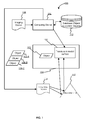
- FIG. 1 illustrates an exemplary system 100 for projecting content on an interactive surface for an immersive experience in accordance with some embodiments of the present disclosure.
- the system 100 comprises a translucent surface/model 102 disposed on at least one mounting means 104.
- the mounting means 104 may be a glass table.
- the mounting means 104 includes at least a portion of it being transparent.
- the translucent surface/model 102 may be built using low cost material like tracing paper and is an interactive surface. These are real, three dimensional models that can be created as per use case. For example, experience of reading a book may be provided by creating a model of the book. Content may be projected from beneath onto this model/surface.
- an object 106 may be placed on the mounting means 104.
- the object 106 is placed on the transparent portion of the mounting means 104.
- the object 106 may be cards.
- the object 106 may be selected from a plurality of objects (106-a, 106-b, 106-c.).
- the object 106 may act as a content cue for changing the projected content on the translucent model/surface 102.
- the content cue may be recognized based on color, a geometric shape, a quick response (QR) code, or text associated with the object 106.
- the content cue may be recognized by detecting the object 106. This detection is performed by one or more imaging devices 108.
- the one or more imaging devices 108 may be low cost cameras.
- the one or more imaging devices 108 may be communicatively coupled to one or more computing devices 110.
- the one or more computing devices 110 may be a tablet, phablet, personal digital assistant (PDA), laptop, personal computer etc.
- the one or more computing devices 110 are further in communication with a database 112.
- the database 112 includes information regarding the mapping of the content cue associated with the object 106 to the content stored in the database 112.
- a first content may be displayed on the computing device 110.
- the first content may be a "Hello" message.
- the computing device 110 communicates the first content to long throw projector 114 that further communicates the first content to an adjustable mirror 116 that reflects the first content on the translucent model/surface 102, contributing to the cost effectiveness of the system 100.
- the first content is projected from behind (rear projection) on the translucent model/surface 102, thereby avoiding shadows.
- the arrangement of the long throw projector 114 and the adjustable mirror 116 replaces a short throw projector which can be costly.
- the object 106 may be detected by the imaging device 108.
- the detected object 106 is communicated to the computing device 110.
- a second content mapped to the object 106 is retrieved by the computing device 110.
- the computing device 110 communicates the second content to the long throw projector 114 that further projects the second content to the adjustable mirror 116 that reflects the second content on the translucent model/surface 102, thereby updating the projected first content to the second content.
- FIG. 2 is a flowchart 200 for illustrating an exemplary method of projecting content on the translucent model/surface 102 according to some embodiments of the present disclosure.
- the translucent model/surface 102 displays a first content.
- the first content may be static content.
- the static content may be a "Hello" message.
- the object 106 is placed on the transparent area of the mounting means 104.
- the object 106 is detected and identified by the imaging device 108 coupled to the computing device 110.
- the object 106 is matched/mapped to the pre-stored second content and the second content is selected for projection.
- the second content may be the content of interest to a user or relevant content.
- the selected second content is communicated to the long throw projector 114 that is connected to the computing device 110.
- the second content is projected to the adjustable mirror 116 that is placed in front of the long throw projector 114.
- the adjustable mirror 116 projects the second content to the translucent surface/model 102.
- the translucent surface/model 102 is placed on the mounting means 104.
- the present disclosure offers many advantages.
- the system 100 is highly affordable for mass deployment. Maintenance of the system 100 is easy because it involves simple set up and low cost materials like tracing paper.
- the system 100 is not constrained only to plain surfaces. Any customizable translucent model/surface 102 can be created and used that offers a reasonably good immersive user experience.
- the system 100 is cost effective as it can be attached and detached . This helps in making the system portable.
Landscapes
- Engineering & Computer Science (AREA)
- General Engineering & Computer Science (AREA)
- Multimedia (AREA)
- Theoretical Computer Science (AREA)
- Human Computer Interaction (AREA)
- Physics & Mathematics (AREA)
- General Physics & Mathematics (AREA)
- Signal Processing (AREA)
- Processing Or Creating Images (AREA)
- User Interface Of Digital Computer (AREA)
Abstract
Description
- This disclosure relates generally to the projection of content on an interactive surface, and more particularly to systems and methods for a simple and affordable interactive surface using custom-built translucent models for an immersive experience.
- The provision of an immersive experience is playing a key role in the digital world. Interactive surfaces are becoming common components of information based activities. Digital information can be displayed on the surface of desks, tables, or walls, and can be manipulated using multi-touch interfaces and tangible input devices. There are a number of interactive surface solutions available that give an immersive experience. Some examples include: a) Bradesco next life cycle; b) ActivTable from Promethean.
- These solutions may offer a good user experience but are expensive. Mass deployment and maintenance of these solutions is therefore a challenge. Further, these solutions need plain level surfaces. Also, in many scenarios, not all features provided by the above solutions may be needed as the desire may be to create a simple immersive user experience. Due to their expensive nature that results from the large number of features, some known interactive surface solutions are considered unaffordable for relatively simple applications where less complicated features are desired.
- In view of the above drawbacks associated with the existing solutions, there is a desire to provide a less costly, more easy to customize, and sufficiently effective infrastructure for an immersive experience.
- Disclosed herein is a method of projecting content on an interactive translucent surface. The method includes projecting a first content on the interactive translucent surface; placing at least one object on at least one mounting means; detecting, using at least one imaging device, the at least one object placed on the at least one mounting means; retrieving a second content from a database, the second content being mapped to the detected object; and updating the first content to the second content on the interactive translucent surface.
- The interactive translucent surface may be made from tracing paper.
- The mounting means may be a transparent table.
- The object may be placed on the transparent portion.
- The interactive translucent surface may comprise a customizable three dimensional model of at least one of book, menu card, and paper.
- In an aspect of the invention, a system for projecting content is disclosed. The system includes an interactive translucent surface for displaying a first content;
at least one mounting means; at least one imaging device to detect at least one object disposed on the at least one mounting means; a computing device to map the at least one object to a second content, the computing device coupled to the imaging device; and wherein the first content on the interactive translucent surface is modified to the second content in response to the at least one object being mapped to the second content. - It is to be understood that both the foregoing general description and the following detailed description are exemplary and explanatory only and are not restrictive of the invention, as claimed.
- The accompanying drawings, which are incorporated in and constitute a part of this disclosure, illustrate exemplary embodiments and, together with the description, serve to explain the disclosed principles.
-
FIG. 1 illustrates an exemplary system for projecting content on an interactive surface for an immersive experience in accordance with some embodiments of the present disclosure; and -
FIG. 2 is a flowchart for illustrating an exemplary method of projecting content on the translucent model/surface according to some embodiments of the present disclosure. - Exemplary embodiments are described with reference to the accompanying drawings. Wherever convenient, the same reference numbers are used throughout the drawings to refer to the same or like parts. While examples and features of the disclosed principles are described herein, modifications, adaptations, and other implementations are possible without departing from the scope of the disclosed embodiments. It is intended that the following detailed description be considered as exemplary only, with the true scope being indicated by the following claims.
- In the present disclosure, the word "exemplary" is used herein to mean "serving as an example, instance, or illustration." Any embodiment or implementation of the present disclosure described herein as "exemplary" is not necessarily to be construed as preferred or advantageous over other embodiments.
- While the present disclosure is susceptible to various modifications and alternative forms, specific embodiment thereof has been shown by way of example in the drawings and will be described in detail below. It should be understood, however that it is not intended to limit the disclosure to the particular forms disclosed, but on the contrary, the disclosure is to cover all modifications, equivalents, and alternative falling within the scope of the disclosure.
- The terms "comprises", "comprising", or any other variations thereof, are intended to cover a non-exclusive inclusion, such that a setup, device or method that comprises a list of components or steps does not include only those components or steps but may include other components or steps not expressly listed or inherent to such setup or device or method. In other words, one or more elements in a system or apparatus preceded by "comprises... a" does not, without more constraints, preclude the existence of other elements or additional elements in the system or apparatus.
- In the following detailed description of the embodiments of the disclosure, reference is made to the accompanying drawings that form a part hereof, and in which are shown by way of illustration specific embodiments in which the disclosure may be practiced. These embodiments are described in sufficient detail to enable those skilled in the art to practice the disclosure, and it is to be understood that other embodiments may be utilized and that changes may be made without departing from the scope of the present disclosure. The following description is, therefore, not to be taken in a limiting sense.
- The present disclosure discloses systems and methods for a simple and affordable interactive surface using custom-built translucent models for an immersive experience. The present disclosure provides a solution that may be affordable and easy to maintain, and may offer a reasonably good immersive experience. Instead of using only plain level surfaces, the disclosure may use customizable low-cost translucent models of everyday objects which have surfaces for interaction. These everyday objects include books, papers, menu cards in restaurants, etc.
- The system uses following components:
- A translucent surface (can be a plain surface or a translucent model of an everyday object).
- A transparent surface for object detection.
- A long throw projector.
- An imaging device.
- An adjustable mirror.
- The system may be implemented using a short throw projector for:
- Short distance projection
- Avoiding shadows
- However, these projectors may be costly. To reduce cost and avoid shadows, a long throw projector may be converted into a short throw projector using a mirror.
- The system may use models of everyday objects with affordable material. Further, the use of a short throw projector may be obviated by using a long throw projector and a mirror.
-
FIG. 1 illustrates anexemplary system 100 for projecting content on an interactive surface for an immersive experience in accordance with some embodiments of the present disclosure. Referring toFIG. 1 , thesystem 100 comprises a translucent surface/model 102 disposed on at least onemounting means 104. The mounting means 104 may be a glass table. The mounting means 104 includes at least a portion of it being transparent. The translucent surface/model 102 may be built using low cost material like tracing paper and is an interactive surface. These are real, three dimensional models that can be created as per use case. For example, experience of reading a book may be provided by creating a model of the book. Content may be projected from beneath onto this model/surface. - Further, an
object 106 may be placed on the mounting means 104. In an exemplary embodiment, theobject 106 is placed on the transparent portion of the mounting means 104. For example, theobject 106 may be cards. Theobject 106 may be selected from a plurality of objects (106-a, 106-b, 106-c....). Theobject 106 may act as a content cue for changing the projected content on the translucent model/surface 102. According to some embodiments, the content cue may be recognized based on color, a geometric shape, a quick response (QR) code, or text associated with theobject 106. - The content cue may be recognized by detecting the
object 106. This detection is performed by one ormore imaging devices 108. The one ormore imaging devices 108 may be low cost cameras. The one ormore imaging devices 108 may be communicatively coupled to one ormore computing devices 110. In an exemplary embodiment, the one ormore computing devices 110 may be a tablet, phablet, personal digital assistant (PDA), laptop, personal computer etc. - The one or
more computing devices 110 are further in communication with adatabase 112. Thedatabase 112 includes information regarding the mapping of the content cue associated with theobject 106 to the content stored in thedatabase 112. - Initially, a first content may be displayed on the
computing device 110. The first content may be a "Hello" message. Thecomputing device 110 communicates the first content to long throw projector 114 that further communicates the first content to anadjustable mirror 116 that reflects the first content on the translucent model/surface 102, contributing to the cost effectiveness of thesystem 100. As noted above, the first content is projected from behind (rear projection) on the translucent model/surface 102, thereby avoiding shadows. The arrangement of the long throw projector 114 and theadjustable mirror 116 replaces a short throw projector which can be costly. - Further, the
object 106 may be detected by theimaging device 108. The detectedobject 106 is communicated to thecomputing device 110. Based on the content cue that may be recognized based on color, geometric shape, a quick response (QR) code, or text associated with theobject 106, a second content mapped to theobject 106 is retrieved by thecomputing device 110. Thecomputing device 110 communicates the second content to the long throw projector 114 that further projects the second content to theadjustable mirror 116 that reflects the second content on the translucent model/surface 102, thereby updating the projected first content to the second content. -
FIG. 2 is aflowchart 200 for illustrating an exemplary method of projecting content on the translucent model/surface 102 according to some embodiments of the present disclosure. - At
step 202, the translucent model/surface 102 displays a first content. The first content may be static content. As discussed earlier, the static content may be a "Hello" message. - At
step 204, theobject 106 is placed on the transparent area of the mounting means 104. - At
step 206, theobject 106 is detected and identified by theimaging device 108 coupled to thecomputing device 110. - At
step 208, theobject 106 is matched/mapped to the pre-stored second content and the second content is selected for projection. The second content may be the content of interest to a user or relevant content. - At
step 210, the selected second content is communicated to the long throw projector 114 that is connected to thecomputing device 110. - At
step 212, the second content is projected to theadjustable mirror 116 that is placed in front of the long throw projector 114. - At
step 214, theadjustable mirror 116 projects the second content to the translucent surface/model 102. The translucent surface/model 102 is placed on the mounting means 104. - The present disclosure offers many advantages. The
system 100 is highly affordable for mass deployment. Maintenance of thesystem 100 is easy because it involves simple set up and low cost materials like tracing paper. Thesystem 100 is not constrained only to plain surfaces. Any customizable translucent model/surface 102 can be created and used that offers a reasonably good immersive user experience. Thesystem 100 is cost effective as it can be attached and detached . This helps in making the system portable. - It is intended that the disclosure and examples be considered as exemplary only, with a true scope of disclosed embodiments being indicated by the following claims.
Claims (15)
- A method of projecting content on an interactive translucent surface, the method comprising:projecting a first content on the interactive translucent surface;placing at least one object on at least one mounting means;detecting, using at least one imaging device, the at least one object placed on the at least one mounting means;retrieving a second content from a database, the second content being mapped to the detected object; andupdating the first content to the second content on the interactive translucent surface.
- The method of claim 1, wherein projecting the first content on the interactive translucent surface comprises:projecting, by a long throw projector, the first content on an adjustable mirror; andreflecting, by the adjustable mirror, the first content on the interactive translucent surface.
- The method of claim 2, wherein updating the first content to the second content on the interactive translucent surface comprises:projecting, by the long throw projector, the retrieved second content on the adjustable mirror; andreflecting, by the adjustable mirror, the second content on the interactive translucent surface.
- The method of any one of claims 1 to 3, wherein mapping of the second content to the detected object is based on at least one of a color, a quick response code (QR code), and a geometric shape associated with the detected object.
- The method of any one of claims 1 to 4 , further comprising forwarding information associated with the detected object to a computing device, the computing device being communicatively coupled to the imaging device.
- The method of any one of claims 1 to 5, wherein the interactive translucent surface is disposed on at least one mounting means, the at least one mounting means comprising at least a transparent portion.
- A system for projecting content, the system comprising:an interactive translucent surface for displaying a first content;at least one mounting means;at least one imaging device to detect at least one object disposed on the at least one mounting means;a computing device to map the at least one object to a second content, the computing device coupled to the imaging device; andwherein the first content on the interactive translucent surface is modified to the second content in response to the at least one object being mapped to the second content.
- The system of claim 7, further comprising:a long throw projector to project the first content on an adjustable mirror; andan adjustable mirror to reflect the first content on the interactive translucent surface.
- The system of claim 8, wherein updating the first content to the second content on the interactive translucent surface comprises:projecting the second content on the adjustable mirror; andreflecting, by the adjustable mirror, the second content on the interactive translucent surface.
- The system of any one of claims 7 to 9, wherein the computing device is configured to map the at least one object to the second content based on at least one of a color, a quick response code (QR code), and a geometric shape associated with the detected object.
- The method of any one of claims 1 to 6 or the system of any one of claims 7 to 10, wherein the interactive translucent surface is made from tracing paper.
- The system of any one of claims 7 to 11, wherein the mounting means comprise at least a transparent portion.
- The method of claim 6 or the system of any one of claims 7 to 12, wherein the mounting means is a transparent table.
- The method of claim 6 or the system of claim 12, wherein the at least one object is placed on the transparent portion.
- The method of any one of claims 1 to 6 or the system of any one of claims 7 to 14, wherein the interactive translucent surface comprises a customizable three dimensional model of at least one of a book, a menu card, and a paper.
Applications Claiming Priority (2)
| Application Number | Priority Date | Filing Date | Title |
|---|---|---|---|
| IN2869CH2015 IN2015CH02869A (en) | 2015-06-09 | 2015-06-09 | |
| US14/814,811 US20160364084A1 (en) | 2015-06-09 | 2015-07-31 | System and method for interactive surface using custom-built translucent models for immersive experience |
Publications (2)
| Publication Number | Publication Date |
|---|---|
| EP3104262A2 true EP3104262A2 (en) | 2016-12-14 |
| EP3104262A3 EP3104262A3 (en) | 2017-07-26 |
Family
ID=54770850
Family Applications (1)
| Application Number | Title | Priority Date | Filing Date |
|---|---|---|---|
| EP15196756.9A Withdrawn EP3104262A3 (en) | 2015-06-09 | 2015-11-27 | Systems and methods for interactive surface using custom-built translucent models for immersive experience |
Country Status (1)
| Country | Link |
|---|---|
| EP (1) | EP3104262A3 (en) |
Family Cites Families (5)
| Publication number | Priority date | Publication date | Assignee | Title |
|---|---|---|---|---|
| US7397464B1 (en) * | 2004-04-30 | 2008-07-08 | Microsoft Corporation | Associating application states with a physical object |
| US7467380B2 (en) * | 2004-05-05 | 2008-12-16 | Microsoft Corporation | Invoking applications with virtual objects on an interactive display |
| JP4991154B2 (en) * | 2005-06-03 | 2012-08-01 | 株式会社リコー | Image display device, image display method, and command input method |
| US8063888B2 (en) * | 2007-02-20 | 2011-11-22 | Microsoft Corporation | Identification of devices on touch-sensitive surface |
| US8545321B2 (en) * | 2007-11-09 | 2013-10-01 | Igt | Gaming system having user interface with uploading and downloading capability |
-
2015
- 2015-11-27 EP EP15196756.9A patent/EP3104262A3/en not_active Withdrawn
Non-Patent Citations (1)
| Title |
|---|
| None |
Also Published As
| Publication number | Publication date |
|---|---|
| EP3104262A3 (en) | 2017-07-26 |
Similar Documents
| Publication | Publication Date | Title |
|---|---|---|
| JP5026079B2 (en) | Presentation system | |
| US9805511B2 (en) | Interacting with data fields on a page using augmented reality | |
| CN110716645A (en) | Augmented reality data presentation method and device, electronic equipment and storage medium | |
| KR20230022269A (en) | Augmented reality data presentation method and apparatus, electronic device, and storage medium | |
| US9607094B2 (en) | Information communication method and information communication apparatus | |
| US20160173840A1 (en) | Information output control device | |
| US20170053449A1 (en) | Apparatus for providing virtual contents to augment usability of real object and method using the same | |
| AU2011384474B2 (en) | Information processing system, method for controlling information processing system, program, and information recording medium | |
| CN106097794A (en) | The Chinese phonetic alphabet based on augmented reality combination is recognized reading learning system and recognizes reading method | |
| US10432572B2 (en) | Content posting method and apparatus | |
| KR102175519B1 (en) | Apparatus for providing virtual contents to augment usability of real object and method using the same | |
| US20160364084A1 (en) | System and method for interactive surface using custom-built translucent models for immersive experience | |
| JPWO2010018770A1 (en) | Image display device | |
| CN204515768U (en) | For the Map service system of augmented reality | |
| WO2016003436A1 (en) | Character recognition in real-time video streams | |
| KR102013622B1 (en) | Apparatus and system for projection mapping | |
| CN114429632B (en) | Methods, devices, electronic equipment and computer storage media for identifying click-to-read content | |
| CN103793528B (en) | Method and device for obtaining network addresses | |
| US20220343571A1 (en) | Information processing system, information processing apparatus, and method of processing information | |
| CN106251714B (en) | Simulation teaching system and method | |
| JP7786476B2 (en) | Output control system, output control method, and program | |
| KR101572349B1 (en) | Voting system and object presence system using computing device and operatiog method thereof | |
| CN109358798B (en) | Touch operation method, system, device and readable storage medium | |
| JP2019074898A (en) | Information processing device and information processing program | |
| JP2018169677A (en) | Translation system |
Legal Events
| Date | Code | Title | Description |
|---|---|---|---|
| PUAI | Public reference made under article 153(3) epc to a published international application that has entered the european phase |
Free format text: ORIGINAL CODE: 0009012 |
|
| AK | Designated contracting states |
Kind code of ref document: A2 Designated state(s): AL AT BE BG CH CY CZ DE DK EE ES FI FR GB GR HR HU IE IS IT LI LT LU LV MC MK MT NL NO PL PT RO RS SE SI SK SM TR |
|
| AX | Request for extension of the european patent |
Extension state: BA ME |
|
| RIC1 | Information provided on ipc code assigned before grant |
Ipc: H04N 9/31 20060101ALI20170224BHEP Ipc: G06T 19/00 20110101ALI20170224BHEP Ipc: G06F 3/042 20060101AFI20170224BHEP |
|
| PUAL | Search report despatched |
Free format text: ORIGINAL CODE: 0009013 |
|
| AK | Designated contracting states |
Kind code of ref document: A3 Designated state(s): AL AT BE BG CH CY CZ DE DK EE ES FI FR GB GR HR HU IE IS IT LI LT LU LV MC MK MT NL NO PL PT RO RS SE SI SK SM TR |
|
| AX | Request for extension of the european patent |
Extension state: BA ME |
|
| RIC1 | Information provided on ipc code assigned before grant |
Ipc: G06T 19/00 20110101ALI20170616BHEP Ipc: H04N 9/31 20060101ALI20170616BHEP Ipc: G06F 3/042 20060101AFI20170616BHEP |
|
| 17P | Request for examination filed |
Effective date: 20180125 |
|
| RBV | Designated contracting states (corrected) |
Designated state(s): AL AT BE BG CH CY CZ DE DK EE ES FI FR GB GR HR HU IE IS IT LI LT LU LV MC MK MT NL NO PL PT RO RS SE SI SK SM TR |
|
| 17Q | First examination report despatched |
Effective date: 20190919 |
|
| STAA | Information on the status of an ep patent application or granted ep patent |
Free format text: STATUS: THE APPLICATION HAS BEEN WITHDRAWN |
|
| 18W | Application withdrawn |
Effective date: 20191106 |