EP3104041A1 - Ball screw - Google Patents
Ball screw Download PDFInfo
- Publication number
- EP3104041A1 EP3104041A1 EP14883716.4A EP14883716A EP3104041A1 EP 3104041 A1 EP3104041 A1 EP 3104041A1 EP 14883716 A EP14883716 A EP 14883716A EP 3104041 A1 EP3104041 A1 EP 3104041A1
- Authority
- EP
- European Patent Office
- Prior art keywords
- nuts
- cooling
- nut
- ball screw
- flow channel
- Prior art date
- Legal status (The legal status is an assumption and is not a legal conclusion. Google has not performed a legal analysis and makes no representation as to the accuracy of the status listed.)
- Withdrawn
Links
- 238000001816 cooling Methods 0.000 claims abstract description 58
- 239000002826 coolant Substances 0.000 claims abstract description 36
- 230000036316 preload Effects 0.000 claims abstract description 35
- 125000006850 spacer group Chemical group 0.000 claims description 7
- 230000007246 mechanism Effects 0.000 abstract description 2
- 238000005096 rolling process Methods 0.000 description 10
- 230000008878 coupling Effects 0.000 description 6
- 238000010168 coupling process Methods 0.000 description 6
- 238000005859 coupling reaction Methods 0.000 description 6
- 238000012423 maintenance Methods 0.000 description 6
- 239000000463 material Substances 0.000 description 4
- 230000006866 deterioration Effects 0.000 description 3
- 230000000694 effects Effects 0.000 description 3
- 239000012530 fluid Substances 0.000 description 3
- 239000007789 gas Substances 0.000 description 3
- 230000020169 heat generation Effects 0.000 description 3
- 239000003921 oil Substances 0.000 description 3
- 235000019198 oils Nutrition 0.000 description 3
- 230000002265 prevention Effects 0.000 description 3
- XLYOFNOQVPJJNP-UHFFFAOYSA-N water Substances O XLYOFNOQVPJJNP-UHFFFAOYSA-N 0.000 description 3
- QGZKDVFQNNGYKY-UHFFFAOYSA-N Ammonia Chemical compound N QGZKDVFQNNGYKY-UHFFFAOYSA-N 0.000 description 2
- XKRFYHLGVUSROY-UHFFFAOYSA-N Argon Chemical compound [Ar] XKRFYHLGVUSROY-UHFFFAOYSA-N 0.000 description 2
- IJGRMHOSHXDMSA-UHFFFAOYSA-N Atomic nitrogen Chemical compound N#N IJGRMHOSHXDMSA-UHFFFAOYSA-N 0.000 description 2
- CURLTUGMZLYLDI-UHFFFAOYSA-N Carbon dioxide Chemical compound O=C=O CURLTUGMZLYLDI-UHFFFAOYSA-N 0.000 description 2
- 230000006872 improvement Effects 0.000 description 2
- NNPPMTNAJDCUHE-UHFFFAOYSA-N isobutane Chemical compound CC(C)C NNPPMTNAJDCUHE-UHFFFAOYSA-N 0.000 description 2
- 239000007788 liquid Substances 0.000 description 2
- 238000000034 method Methods 0.000 description 2
- 239000004215 Carbon black (E152) Substances 0.000 description 1
- 230000004913 activation Effects 0.000 description 1
- 239000000654 additive Substances 0.000 description 1
- 229910021529 ammonia Inorganic materials 0.000 description 1
- 239000010775 animal oil Substances 0.000 description 1
- 229910052786 argon Inorganic materials 0.000 description 1
- 239000001273 butane Substances 0.000 description 1
- -1 butane or isobutane) Chemical class 0.000 description 1
- 229910002092 carbon dioxide Inorganic materials 0.000 description 1
- 239000001569 carbon dioxide Substances 0.000 description 1
- 230000008859 change Effects 0.000 description 1
- 230000012447 hatching Effects 0.000 description 1
- 239000001307 helium Substances 0.000 description 1
- 229910052734 helium Inorganic materials 0.000 description 1
- SWQJXJOGLNCZEY-UHFFFAOYSA-N helium atom Chemical compound [He] SWQJXJOGLNCZEY-UHFFFAOYSA-N 0.000 description 1
- 229930195733 hydrocarbon Natural products 0.000 description 1
- 150000002430 hydrocarbons Chemical class 0.000 description 1
- 239000011261 inert gas Substances 0.000 description 1
- 239000001282 iso-butane Substances 0.000 description 1
- 239000000314 lubricant Substances 0.000 description 1
- 238000005461 lubrication Methods 0.000 description 1
- 239000002480 mineral oil Substances 0.000 description 1
- 239000000203 mixture Substances 0.000 description 1
- 238000012986 modification Methods 0.000 description 1
- 230000004048 modification Effects 0.000 description 1
- IJDNQMDRQITEOD-UHFFFAOYSA-N n-butane Chemical compound CCCC IJDNQMDRQITEOD-UHFFFAOYSA-N 0.000 description 1
- OFBQJSOFQDEBGM-UHFFFAOYSA-N n-pentane Natural products CCCCC OFBQJSOFQDEBGM-UHFFFAOYSA-N 0.000 description 1
- 229910052757 nitrogen Inorganic materials 0.000 description 1
- 235000015112 vegetable and seed oil Nutrition 0.000 description 1
- 239000008158 vegetable oil Substances 0.000 description 1
Images


Classifications
-
- F—MECHANICAL ENGINEERING; LIGHTING; HEATING; WEAPONS; BLASTING
- F16—ENGINEERING ELEMENTS AND UNITS; GENERAL MEASURES FOR PRODUCING AND MAINTAINING EFFECTIVE FUNCTIONING OF MACHINES OR INSTALLATIONS; THERMAL INSULATION IN GENERAL
- F16H—GEARING
- F16H57/00—General details of gearing
- F16H57/04—Features relating to lubrication or cooling or heating
- F16H57/048—Type of gearings to be lubricated, cooled or heated
- F16H57/0497—Screw mechanisms
-
- F—MECHANICAL ENGINEERING; LIGHTING; HEATING; WEAPONS; BLASTING
- F16—ENGINEERING ELEMENTS AND UNITS; GENERAL MEASURES FOR PRODUCING AND MAINTAINING EFFECTIVE FUNCTIONING OF MACHINES OR INSTALLATIONS; THERMAL INSULATION IN GENERAL
- F16H—GEARING
- F16H25/00—Gearings comprising primarily only cams, cam-followers and screw-and-nut mechanisms
- F16H25/18—Gearings comprising primarily only cams, cam-followers and screw-and-nut mechanisms for conveying or interconverting oscillating or reciprocating motions
- F16H25/20—Screw mechanisms
- F16H25/22—Screw mechanisms with balls, rollers, or similar members between the co-operating parts; Elements essential to the use of such members
- F16H25/2204—Screw mechanisms with balls, rollers, or similar members between the co-operating parts; Elements essential to the use of such members with balls
- F16H25/2209—Screw mechanisms with balls, rollers, or similar members between the co-operating parts; Elements essential to the use of such members with balls with arrangements for taking up backlash
-
- F—MECHANICAL ENGINEERING; LIGHTING; HEATING; WEAPONS; BLASTING
- F16—ENGINEERING ELEMENTS AND UNITS; GENERAL MEASURES FOR PRODUCING AND MAINTAINING EFFECTIVE FUNCTIONING OF MACHINES OR INSTALLATIONS; THERMAL INSULATION IN GENERAL
- F16H—GEARING
- F16H25/00—Gearings comprising primarily only cams, cam-followers and screw-and-nut mechanisms
- F16H25/18—Gearings comprising primarily only cams, cam-followers and screw-and-nut mechanisms for conveying or interconverting oscillating or reciprocating motions
- F16H25/20—Screw mechanisms
- F16H25/24—Elements essential to such mechanisms, e.g. screws, nuts
- F16H25/2418—Screw seals, wipers, scrapers or the like
-
- F—MECHANICAL ENGINEERING; LIGHTING; HEATING; WEAPONS; BLASTING
- F16—ENGINEERING ELEMENTS AND UNITS; GENERAL MEASURES FOR PRODUCING AND MAINTAINING EFFECTIVE FUNCTIONING OF MACHINES OR INSTALLATIONS; THERMAL INSULATION IN GENERAL
- F16H—GEARING
- F16H57/00—General details of gearing
- F16H57/04—Features relating to lubrication or cooling or heating
- F16H57/0412—Cooling or heating; Control of temperature
Definitions
- the present invention relates to ball screws, more particularly to a ball screw having a function to cool a nut.
- Types of installing the cooling portion in the conventional ball screw include a shaft center cooling type and a nut cooling type.
- the shaft center cooling type is a configured such that the screw shaft is a cooling target so that the cooling portion is provided in the screw shaft.
- the screw shaft is hollow to allow a cooling medium to flow through the screw shaft.
- the nut cooling type is configured such that the nut is a cooling target and the cooling portion is provided in the nut.
- the shaft center cooling type may have a drawback in cost for making a hollow hole in the screw shaft, when the shaft center cooling type is used in a large and long ball screw device. Therefore, the nut cooling type is often used.
- Patent Literature 1 The technique disclosed in Patent Literature 1 is given as the ball screw using such a nut cooling type is. Specifically, according to the technique in Patent Literature 1, a cooling medium is made to pass through a flow channel provided in a nut in an axial direction to cool the nut.
- the mainly used ones of recent large and long ball screws are ball screws manufactured by using double nut preload. In such ball screws, it is important to efficiently cool plural nuts, and prevent leakage of the cooling medium during disassembly, assembly, and maintenance.
- Patent Literature 1 Even when the ball screw disclosed in Patent Literature 1 is applied to the ball screw manufactured by using the double nut preload, there is room for improvement in providing a ball screw which achieves a balance between efficient cooling of plural nuts and the prevention of the leakage of the cooling medium.
- the present invention has been made to address the above drawbacks, and has an object to provide a ball screw, which achieves a high cooling efficiency, which prevents the leakage of a cooling medium even during disassembly, assembly, and maintenance, and which achieves a well balance between the cooling efficiency and the prevention of leakage.
- a ball screw includes : a screw shaft in which a spiral groove is arranged on an outer circumferential surface; two nuts, each of which includes a spiral groove facing the spiral groove of the screw shaft, and which are screwed to the screw shaft via a plurality of balls disposed between the spiral grooves of the two nuts and the spiral groove of the screw shaft; and a preload application member configured to apply a preload to the balls, wherein cooling portions are independently provided in the two nuts, respectively, and wherein the cooling portions are respectively provided in the nuts to be symmetric with respect to a space between the two nuts.
- a ball screw including a screw shaft in which a spiral groove is arranged on an outer circumferential surface; two nuts, each of which includes a spiral groove facing the spiral groove of the screw shaft, and which are screwed to the screw shaft via a plurality of balls disposed between the spiral grooves of the two nuts and the spiral groove of the screw shaft; and a preload application member configured to apply a preload to the balls, cooling portions (cooling mechanisms) are independently provided in the two nuts, respectively, and the cooling portions are respectively provided in the nuts to be symmetric with respect to a space between the two nuts.
- the above-described two nuts are incorporated by coupling, connecting, or adjacently arranged.
- each of the cooling portions is a flow channel to pass a cooling medium
- the flow channel may include at least one of an axial flow channel extending along the axial direction and a circumferential flow channel provided so as to intersect at right angles with the axial direction. That is, each of the cooling portions has a flow channel to pass the cooling medium as an independent channel.
- Each of these flow channels includes at least one of an axial flow channel and a circumferential flow channel.
- the axial flow channel is a flow channel axially provided between the inner circumference of the nut and the outer circumference of the nut.
- the circumferential flow channel is a flow channel provided between the inner circumference of the nut and the outer circumference of the nut in a direction that intersects at right angles with the axis of the nut.
- the cooling portions are configured so that the cooling medium can independently circulate in each of the nuts.
- the ball screw may be configured so that each of the nuts is provided with an inflow opening which is coupled to the flow channels and into which the cooling medium flows, and a discharge opening which is coupled to the flow channels and which discharges the cooling medium, preferably. That is, each of the nuts may be configured to have at least one pair of an inflow opening which is an inflow portion for the cooling medium and a discharge opening which is an outflow portion.
- the ball screw may be configured so that the preload application member is a spacer which is coaxial with the two nuts and which is disposed between the two nuts.
- the preload application member it is possible to use aconfigurationwhichuses, for example, fixed position preload produced by a positional adjustment between the nuts, constant pressure preload produced by an elastic body such as a spring, or variable control preload to set a predetermined preload load by using fluid pressure or an actuator such as a piezoelectric element. More specifically, it is possible to use a configuration in which the above configuration of the preload is disposed between the nuts so that a plurality of nuts press or pull one another.
- a ball screw which achieves a high cooling efficiency, which prevents leakage of a cooling medium even during disassembly, assembly, and maintenance, and which achieves a well balance between the cooling efficiency and the prevention of leakage.
- FIG. 1 is a side view of a configuration of a ball screw in one embodiment of the present invention.
- FIG. 2 is a partial sectional view of a configuration of the ball screw in one embodiment of the present invention.
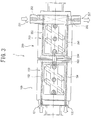
- FIG. 3 is a side view of a configuration of the ball screw in one embodiment of the present invention, and flow channels are highlighted by hatching.
- a ball screw 1 in one embodiment of the present embodiment includes two nuts (which are a first nut 100 and a second nut 200), a screw shaft 300, and a preload application member which is provided between the two nuts and which is configured to apply preload to the ball.
- the first nut 100 includes a body portion 100A cylindrically formed to have an inside diameter larger than the outside diameter of the screw shaft 300, a cap 110, and tubes 120 and 121.
- the cap 110 is attached to one end of the body portion 100A by, for example, unillustrated screws via a seal material 111.
- the tubes 120 and 121 are members for rolling element circulation provided in a flat portion 115 of the outer circumferential surface of the body portion 100A, and are fixed by a holding plate 122 fastened to the first nut 100 by screws 123 to 125.
- the first nut 100 is known as a flangeless type nut.
- the second nut 200 includes a body portion 200A cylindrically formed to have an inside diameter larger than the outside diameter of the screw shaft 300, a flange portion 201 provided at one end of the body portion 200A, a cap 210, and tubes 220 and 221.
- the cap 210 is attached to an end of the body portion 200A by, for example, unillustrated screws via a seal material 211.
- the tubes 220 and 221 are members for rolling element circulation provided in a flat portion 215 of the outer circumferential surface of the body portion 200A, and are fixed by a holding plate 222 fastened to the second nut 200 by screws 223 to 225.
- a spiral groove 101 is formed on an inner circumferential surface 100a of the first nut 100 so as to face a spiral groove 301 spirally formed on an outer circumferential surface 300a of the screw shaft 300.
- the spiral groove 201 is also formed on an inner circumferential surface 200a of the second nut 200 so as to face the spiral groove 301 of the screw shaft 300.
- the first nut 100 and the second nut 200 are coaxially arranged in the axial direction of the screw shaft 300, and are screwed with the screw shaft 300 by plural rolling elements B provided between the spiral groove 101 and the spiral groove 201.
- the rolling elements B are capable of rolling through a rolling channel formed by the spiral groove 301 and the spiral grooves 101 and 201, so that the screw shaft 300, and the first nut 100, and the second nut 200 can relatively move in the axial direction.
- a spacer 128 is provided coaxially with the first nut 100 and the second nut 200 between the other end of the first nut 100 and the other end of the second nut 200 via seal materials 129 and 130.
- the first nut 100 and the second nut 200 are coupled to each other by a coupling member 127 via the spacer 128 and the seal materials 129 and 130. Only one coupling member 127 is illustrated in FIG. 1 and FIG. 2 , but the first nut 100 and the second nut 200 may be coupled to each other at plural places by plural coupling members 127 as needed.
- the first nut 100 and the second nut 200 are coupled to each other by the coupling member 127 via the spacer 128, so that the spacer 128 and the coupling member 127 function as preload application members, leading to a state in which what is known as fixed position preload is applied.
- two-point contact preload in a pulling direction is applied to the first nut 100 and the second nut 200 to cancel an increase in preload torque caused by cooling the first nut 100 and the second nut 200. This configuration enables efficient cooling of the first nut 100 and the second nut 200.
- the preload application member it is possible to select a configuration which uses, for example, not only the fixed position preload produced by a positional adjustment between the above nuts 100 and 200 but also constant pressure preload produced by an elastic body such as a spring, fluid pressure preload, or variable control preload to set a predetermined preload by using an actuator such as a piezoelectric element.
- the first nut 100 and the second nut 200 respectively include cooling portions 150 and 250 which independently cool the nuts 100 and 200. These cooling portions 150 and 250 are respectively arranged in the nuts 100 and 200 symmetrically with respect to a virtual area between the two nuts 100 and 200.
- the area is a virtual plane A (see FIG. 2 ) extending through the midpoint in the axial direction of the spacer 128 and passing perpendicularly to the axial direction.
- the provision of the cooling portions 150 and 250 keeps the weight balance of a ball screw device, and does not prevent smooth activation.
- the configurations of the cooling portions 150 and 250 are not limited in particular, as long as the cooling portions 150 and 250 are provided symmetrically with respect to the virtual area between the two nuts 100 and 200, and as long as the cooling portions 150 and 250 independently cool the first nut 100 and the second nut 200, respectively.
- a suitable configuration can be selected depending on the purpose.
- the cooling portions 150 and 250 include plural flow channels 152 to 154 and 252 to 256 which are respectively pierced in the first nut 100 and the second nut 200 so that a cooling medium can pass through them.
- Each of these flow channels can include at least one of an axial flow channel extending in the axial direction and a circumferential flow channel provided to intersect perpendicularly to the axial direction.
- the aforementioned "axial flow channel” includes the axial flow channels 152 and 154 extending in the axial direction in the first nut 100, and axial flow channels 253 and 255 extending in the axial direction in the second nut 200.
- the axial flow channel 152 and the axial flow channel 253 are flow channels symmetrically provided between the two nuts 100 and 200.
- the axial flow channel 154 and the axial flow channel 255 are flow channels symmetrically provided in the nuts 100 and 200, respectively.
- the aforementioned “circumferential flow channel” includes the circumferential flow channel 153 provided in the circumferential direction to intersect perpendicularly to the axial direction in the first nut 100, and the circumferential flow channels 252, 254, and 256 provided in the circumferential direction to intersect perpendicularly to the axial direction in the second nut 200.
- the circumferential flow channel 153 and the axial flow channel 254 are flow channels symmetrically provided in the nuts 100 and 200, respectively. In this way, the cooling portions 150 and 250 are configured to allow the cooling medium to independently circulate in each of the nuts 100 and 200.
- an inflow opening 151 which is coupled to the flow channels 152 to 154 and into which the cooling medium flows, and a discharge opening 155 configured to discharge the cooling medium may be provided in the first nut 100.
- an inflow opening 251 which is coupled to the flow channels 252 to 256 and into which the cooling medium flows, and a discharge opening 257 configured to discharge the cooling medium may be provided in the second nut 200. That is, each of the nuts 100 and 200 may include at least one pair of the inflow opening 151 or 251, which is an inflow portion for the cooling medium, and a discharge opening 155 or 257, which is a discharge portion.
- the cooling portion 150 of the first nut 100 includes the inflow portion 151 provided at the end of the cap 110 in the axial direction, the axial flow channel 152, the circumferential flow channel 153, the axial flow channel 154, and the discharge portion 155 provided at the end of the cap 110 in the axial direction. That is, a single independent system of flow channel is formed in the first nut 100. Two or more systems of flow channels may be provided as long as the flow channels are independently provided in each of the nuts 100 and 200.
- the cooling portion 250 of the second nut 200 includes the inflow portion 251 provided in the outer circumference of the flange portion 201 in a direction that intersects perpendicularly to the axis, the circumferential flow channel 252, the axial flow channel 253, the circumferential flow channel 254, the axial flow channel 255, the circumferential flow channel 256, and the outflow portion 257 provided in the outer circumference of the flange portion 201 in the direction that intersects perpendicularly to the axis. That is, a single independent system of flow channel is formed in the second nut 200. Two or more systems of flow channels may be provided as long as the flow channels are independently provided in each of the nuts 100 and 200.
- tube taper screws for pipe fastening are provided in the inflow portions 151 and 251 and the discharge portions 155 and 257, so that pipes are connected to these tube taper screws. This configuration enables supply and discharge of the cooling medium.
- a fluid can be used as a fluid to serve as the cooling medium.
- a gas not only air or compressed air but also nitrogen
- an inert gas e.g., argon
- hydrocarbon e.g., butane or isobutane
- helium ammonia
- carbon dioxide or a mixture of the above gases
- a liquid not only water but also a coolant in which antirust is added to water
- a coolant in which various additives are added to water, or various oils as cooling medium oils can be used.
- mineral oils, animal and vegetable oils, or synthetic oils can be used.
- a suitable one of the above may be selected depending on, for example, the use environment.
- the temperature of the cooling medium may be managed and the flow volume may also be managed.
- the cooling medium may be used in a turbulent state.
- the temperature can be managed in each nut, and, for example, the preload can be controlled.
- the positions and sizes of the inflow portions and the discharge portions, and the sectional shape and sectional area of each flow channel can be suitably adjusted depending on the use condition.
- the preload load can be higher, and the ball screw can therefore be suitably applied to what is known as a large-sized ball screw (i.e., the outside diametrical dimension of the screw shaft 300 is substantially 80 nm or more).
- the cooling medium can independently circulate in each of the nuts.
- the cooling efficiency is high.
- Such a high cooling efficiency allows the nuts to be cooled firstly. Then, and the effects of the cooling are transmitted to the balls that are the rolling elements from the spiral grooves on the inner circumferences of the nuts and further transmitted to the spiral groove of the screw shaft, and also cools the screw shaft.
- the preload change and the deterioration of lubrication caused by heat generation are prevented, accordingly.
- the cooling effects are remarkably exhibited, when the preload load is relatively high and when the contact states between the spiral grooves and the rolling elements, and the spiral grooves and the rolling elements are maintained. Therefore, the ball screw according to the present invention is suitable to a relatively large-sized ball screw.
- the flow channel of the cooling medium for cooling is independently provided in each of the nuts. Therefore, for example, even at the time of maintenance in which some of the nuts need to be replaced, the leakage of the cooling medium during maintenance can be effectively prevented when piping to each of the cooling medium flow channels is blacked.
- the ball screw in one embodiment of the present invention can be suitably used as a ball screw which demands processing accuracy in particular and which is used in what is known as a linearly moving part of a large-sized machine tool that may be subject to the maintenance.
- the ball screw in one embodiment of the present invention achieves a high cooling efficiency. Hence, there are no significant changes in the preload and the length of the screw shaft, and excessive heat generation is prevented. Therefore, no significant deterioration of a lubricant can be found. Accordingly, there is no significant deterioration in positioning accuracy of the linearly moving part caused by heat generation in the ball screw, a stable operation in which what is known as torque variation is small can be maintained for a long period of time, and such advantages can be found at even a long screw shaft. Consequently, the ball screws in some embodiments of the present invention are particularly applicable as ball screws used in linearly moving parts of large-sized machine tools for high-precision processing. The ball screw in one embodiment of the present invention can be used together with the shaft center cooling.
- the ball screws in some embodiments of the present invention are applicable as ball screws used in linearly moving parts of large-sized machine tools for high-precision processing.
Landscapes
- Engineering & Computer Science (AREA)
- General Engineering & Computer Science (AREA)
- Mechanical Engineering (AREA)
- Transmission Devices (AREA)
Abstract
There is provided a ball screw that is used to apply a preload to balls and that has a configuration of achieving a balance between the cooling efficiency and ease of assembly and disassembly. To this end, the ball screw includes a screw shaft, and a plurality of nuts movable relative to the screw shaft in an axial direction. Each of the nuts includes flow channels, which are cooling mechanisms and which respectively serve as independent channels to allow a cooling medium to pass through them. These flow channels are provided symmetrically with respect to a space between the nuts, and are configured so that the cooling medium can independently circulate in each of the nuts.
Description
- The present invention relates to ball screws, more particularly to a ball screw having a function to cool a nut.
- There has heretofore been known a ball screw which includes a screw shaft, and a nut that is screwed to the screw shaft via plural rolling elements (e.g., balls) and in which the screw shaft and the nut are relatively rotatable. In this ball screw, frictional heat resulting from a point contact or surface contact is generated between the screw shaft and the nut during rotation. Hence, a cooling portion to reduce the frictional heat is provided in some cases.
- Types of installing the cooling portion in the conventional ball screw include a shaft center cooling type and a nut cooling type. The shaft center cooling type is a configured such that the screw shaft is a cooling target so that the cooling portion is provided in the screw shaft. As an example of this shaft center cooling type, the screw shaft is hollow to allow a cooling medium to flow through the screw shaft. The nut cooling type is configured such that the nut is a cooling target and the cooling portion is provided in the nut.
- Here, the shaft center cooling type may have a drawback in cost for making a hollow hole in the screw shaft, when the shaft center cooling type is used in a large and long ball screw device. Therefore, the nut cooling type is often used.
- The technique disclosed in
Patent Literature 1 is given as the ball screw using such a nut cooling type is. Specifically, according to the technique inPatent Literature 1, a cooling medium is made to pass through a flow channel provided in a nut in an axial direction to cool the nut. - PTL 1:
JP 2010-133556 A - The mainly used ones of recent large and long ball screws are ball screws manufactured by using double nut preload. In such ball screws, it is important to efficiently cool plural nuts, and prevent leakage of the cooling medium during disassembly, assembly, and maintenance.
- However, even when the ball screw disclosed in
Patent Literature 1 is applied to the ball screw manufactured by using the double nut preload, there is room for improvement in providing a ball screw which achieves a balance between efficient cooling of plural nuts and the prevention of the leakage of the cooling medium. - The present invention has been made to address the above drawbacks, and has an object to provide a ball screw, which achieves a high cooling efficiency, which prevents the leakage of a cooling medium even during disassembly, assembly, and maintenance, and which achieves a well balance between the cooling efficiency and the prevention of leakage.
- To achieve the above object, a ball screw according to one embodiment of the present invention includes : a screw shaft in which a spiral groove is arranged on an outer circumferential surface;
two nuts, each of which includes a spiral groove facing the spiral groove of the screw shaft, and which are screwed to the screw shaft via a plurality of balls disposed between the spiral grooves of the two nuts and the spiral groove of the screw shaft; and
a preload application member configured to apply a preload to the balls,
wherein cooling portions are independently provided in the two nuts, respectively, and
wherein the cooling portions are respectively provided in the nuts to be symmetric with respect to a space between the two nuts. - That is, in a ball screw according to one embodiment of the present invention including a screw shaft in which a spiral groove is arranged on an outer circumferential surface; two nuts, each of which includes a spiral groove facing the spiral groove of the screw shaft, and which are screwed to the screw shaft via a plurality of balls disposed between the spiral grooves of the two nuts and the spiral groove of the screw shaft; and a preload application member configured to apply a preload to the balls,
cooling portions (cooling mechanisms) are independently provided in the two nuts, respectively, and
the cooling portions are respectively provided in the nuts to be symmetric with respect to a space between the two nuts. The above-described two nuts are incorporated by coupling, connecting, or adjacently arranged. - Here, in the ball screw, preferably, each of the cooling portions is a flow channel to pass a cooling medium, and the flow channel may include at least one of an axial flow channel extending along the axial direction and a circumferential flow channel provided so as to intersect at right angles with the axial direction. That is, each of the cooling portions has a flow channel to pass the cooling medium as an independent channel. Each of these flow channels includes at least one of an axial flow channel and a circumferential flow channel. The axial flow channel is a flow channel axially provided between the inner circumference of the nut and the outer circumference of the nut. The circumferential flow channel is a flow channel provided between the inner circumference of the nut and the outer circumference of the nut in a direction that intersects at right angles with the axis of the nut. The cooling portions are configured so that the cooling medium can independently circulate in each of the nuts.
- The ball screw may be configured so that each of the nuts is provided with an inflow opening which is coupled to the flow channels and into which the cooling medium flows, and a discharge opening which is coupled to the flow channels and which discharges the cooling medium, preferably. That is, each of the nuts may be configured to have at least one pair of an inflow opening which is an inflow portion for the cooling medium and a discharge opening which is an outflow portion.
- The ball screw may be configured so that the preload application member is a spacer which is coaxial with the two nuts and which is disposed between the two nuts.
- As the preload application member, it is possible to use aconfigurationwhichuses, for example, fixed position preload produced by a positional adjustment between the nuts, constant pressure preload produced by an elastic body such as a spring, or variable control preload to set a predetermined preload load by using fluid pressure or an actuator such as a piezoelectric element. More specifically, it is possible to use a configuration in which the above configuration of the preload is disposed between the nuts so that a plurality of nuts press or pull one another.
- According to one aspect of the present invention, it is possible to provide a ball screw, which achieves a high cooling efficiency, which prevents leakage of a cooling medium even during disassembly, assembly, and maintenance, and which achieves a well balance between the cooling efficiency and the prevention of leakage.
-
-
FIG. 1 is a side view of a configuration of a ball screw in one embodiment of the present invention; -
FIG. 2 is a partial sectional view of a configuration of the ball screw in one embodiment of the present invention; and -
FIG. 3 is a side view of a configuration of the ball screw in one embodiment of the present invention. - Embodiments of the present invention will now be described with reference to the drawings.
-
FIG. 1 is a side view of a configuration of a ball screw in one embodiment of the present invention.FIG. 2 is a partial sectional view of a configuration of the ball screw in one embodiment of the present invention.FIG. 3 is a side view of a configuration of the ball screw in one embodiment of the present invention, and flow channels are highlighted by hatching. - As illustrated in
FIG. 1 , aball screw 1 in one embodiment of the present embodiment includes two nuts (which are afirst nut 100 and a second nut 200), ascrew shaft 300, and a preload application member which is provided between the two nuts and which is configured to apply preload to the ball. - The
first nut 100 includes abody portion 100A cylindrically formed to have an inside diameter larger than the outside diameter of thescrew shaft 300, acap 110, andtubes cap 110 is attached to one end of thebody portion 100A by, for example, unillustrated screws via aseal material 111. Thetubes flat portion 115 of the outer circumferential surface of thebody portion 100A, and are fixed by aholding plate 122 fastened to thefirst nut 100 byscrews 123 to 125. Thefirst nut 100 is known as a flangeless type nut. - The
second nut 200 includes abody portion 200A cylindrically formed to have an inside diameter larger than the outside diameter of thescrew shaft 300, aflange portion 201 provided at one end of thebody portion 200A, acap 210, andtubes cap 210 is attached to an end of thebody portion 200A by, for example, unillustrated screws via aseal material 211. Thetubes flat portion 215 of the outer circumferential surface of thebody portion 200A, and are fixed by aholding plate 222 fastened to thesecond nut 200 byscrews 223 to 225. - Here, as illustrated in
FIG. 2 , aspiral groove 101 is formed on an innercircumferential surface 100a of thefirst nut 100 so as to face aspiral groove 301 spirally formed on an outercircumferential surface 300a of thescrew shaft 300. Thespiral groove 201 is also formed on an innercircumferential surface 200a of thesecond nut 200 so as to face thespiral groove 301 of thescrew shaft 300. Thefirst nut 100 and thesecond nut 200 are coaxially arranged in the axial direction of thescrew shaft 300, and are screwed with thescrew shaft 300 by plural rolling elements B provided between thespiral groove 101 and thespiral groove 201. Thus, the rolling elements B are capable of rolling through a rolling channel formed by thespiral groove 301 and thespiral grooves screw shaft 300, and thefirst nut 100, and thesecond nut 200 can relatively move in the axial direction. - As illustrated in
FIG. 1 andFIG. 2 , aspacer 128 is provided coaxially with thefirst nut 100 and thesecond nut 200 between the other end of thefirst nut 100 and the other end of thesecond nut 200 viaseal materials first nut 100 and thesecond nut 200 are coupled to each other by acoupling member 127 via thespacer 128 and theseal materials coupling member 127 is illustrated inFIG. 1 andFIG. 2 , but thefirst nut 100 and thesecond nut 200 may be coupled to each other at plural places byplural coupling members 127 as needed. - Thus, the
first nut 100 and thesecond nut 200 are coupled to each other by thecoupling member 127 via thespacer 128, so that thespacer 128 and thecoupling member 127 function as preload application members, leading to a state in which what is known as fixed position preload is applied. In theball screw 1 in one embodiment of the present invention, two-point contact preload in a pulling direction is applied to thefirst nut 100 and thesecond nut 200 to cancel an increase in preload torque caused by cooling thefirst nut 100 and thesecond nut 200. This configuration enables efficient cooling of thefirst nut 100 and thesecond nut 200. - As the preload application member, it is possible to select a configuration which uses, for example, not only the fixed position preload produced by a positional adjustment between the
above nuts - The
first nut 100 and thesecond nut 200 respectively include coolingportions portions nuts nuts FIG. 2 ) extending through the midpoint in the axial direction of thespacer 128 and passing perpendicularly to the axial direction. The provision of the coolingportions portions portions nuts portions first nut 100 and thesecond nut 200, respectively. A suitable configuration can be selected depending on the purpose. - For example, as illustrated in
FIG. 1 andFIG. 2 , the coolingportions plural flow channels 152 to 154 and 252 to 256 which are respectively pierced in thefirst nut 100 and thesecond nut 200 so that a cooling medium can pass through them. Each of these flow channels can include at least one of an axial flow channel extending in the axial direction and a circumferential flow channel provided to intersect perpendicularly to the axial direction. The aforementioned "axial flow channel" includes theaxial flow channels first nut 100, andaxial flow channels second nut 200. Among theseaxial flow channels axial flow channel 152 and theaxial flow channel 253 are flow channels symmetrically provided between the twonuts axial flow channel 154 and theaxial flow channel 255 are flow channels symmetrically provided in thenuts - The aforementioned "circumferential flow channel" includes the
circumferential flow channel 153 provided in the circumferential direction to intersect perpendicularly to the axial direction in thefirst nut 100, and thecircumferential flow channels second nut 200. Among thesecircumferential flow channels circumferential flow channel 153 and theaxial flow channel 254 are flow channels symmetrically provided in thenuts portions nuts - In the
ball screw 1 in one embodiment of the present invention, aninflow opening 151 which is coupled to theflow channels 152 to 154 and into which the cooling medium flows, and adischarge opening 155 configured to discharge the cooling medium may be provided in thefirst nut 100. Moreover, in theball screw 1 in one embodiment of the present invention, aninflow opening 251 which is coupled to theflow channels 252 to 256 and into which the cooling medium flows, and adischarge opening 257 configured to discharge the cooling medium may be provided in thesecond nut 200. That is, each of thenuts inflow opening discharge opening - Therefore, as illustrated in
FIG. 1 to FIG. 3 , the coolingportion 150 of thefirst nut 100 includes theinflow portion 151 provided at the end of thecap 110 in the axial direction, theaxial flow channel 152, thecircumferential flow channel 153, theaxial flow channel 154, and thedischarge portion 155 provided at the end of thecap 110 in the axial direction. That is, a single independent system of flow channel is formed in thefirst nut 100. Two or more systems of flow channels may be provided as long as the flow channels are independently provided in each of thenuts - As illustrated in
FIG. 1 to FIG. 3 , the coolingportion 250 of thesecond nut 200 includes theinflow portion 251 provided in the outer circumference of theflange portion 201 in a direction that intersects perpendicularly to the axis, thecircumferential flow channel 252, theaxial flow channel 253, thecircumferential flow channel 254, theaxial flow channel 255, thecircumferential flow channel 256, and theoutflow portion 257 provided in the outer circumference of theflange portion 201 in the direction that intersects perpendicularly to the axis. That is, a single independent system of flow channel is formed in thesecond nut 200. Two or more systems of flow channels may be provided as long as the flow channels are independently provided in each of thenuts - Here, tube taper screws for pipe fastening are provided in the
inflow portions discharge portions - Various gases and liquids can be used as a fluid to serve as the cooling medium. As a gas, not only air or compressed air but also nitrogen, an inert gas (e.g., argon), hydrocarbon (e.g., butane or isobutane), helium, ammonia, carbon dioxide, or a mixture of the above gases can be used. As a liquid, not only water but also a coolant in which antirust is added to water, a coolant in which various additives are added to water, or various oils as cooling medium oils can be used. Specifically, mineral oils, animal and vegetable oils, or synthetic oils can be used. A suitable one of the above may be selected depending on, for example, the use environment. Further, the temperature of the cooling medium may be managed and the flow volume may also be managed. The cooling medium may be used in a turbulent state.
- In one embodiment of the present invention, the temperature can be managed in each nut, and, for example, the preload can be controlled.
- Furthermore, the positions and sizes of the inflow portions and the discharge portions, and the sectional shape and sectional area of each flow channel can be suitably adjusted depending on the use condition.
- According to the ball screw in one embodiment of the present invention, the preload load can be higher, and the ball screw can therefore be suitably applied to what is known as a large-sized ball screw (i.e., the outside diametrical dimension of the
screw shaft 300 is substantially 80 nm or more). - According to the ball screw in one embodiment of the present invention, the cooling medium can independently circulate in each of the nuts. Thus, the cooling efficiency is high. Such a high cooling efficiency allows the nuts to be cooled firstly. Then, and the effects of the cooling are transmitted to the balls that are the rolling elements from the spiral grooves on the inner circumferences of the nuts and further transmitted to the spiral groove of the screw shaft, and also cools the screw shaft. The preload change and the deterioration of lubrication caused by heat generation are prevented, accordingly. The cooling effects are remarkably exhibited, when the preload load is relatively high and when the contact states between the spiral grooves and the rolling elements, and the spiral grooves and the rolling elements are maintained. Therefore, the ball screw according to the present invention is suitable to a relatively large-sized ball screw.
- According to the ball screw in one embodiment of the present invention, even a long (i.e., about 4 m or more) ball screw in which the use of what is known as the shaft center cooling type is difficult can be applied without the shaft center cooling, but the shaft center cooling can be used together when necessary.
- Furthermore, according to the ball screw in one embodiment of the present invention, the flow channel of the cooling medium for cooling is independently provided in each of the nuts. Therefore, for example, even at the time of maintenance in which some of the nuts need to be replaced, the leakage of the cooling medium during maintenance can be effectively prevented when piping to each of the cooling medium flow channels is blacked.
- Thus, the ball screw in one embodiment of the present invention can be suitably used as a ball screw which demands processing accuracy in particular and which is used in what is known as a linearly moving part of a large-sized machine tool that may be subject to the maintenance.
- The ball screw in one embodiment of the present invention achieves a high cooling efficiency. Hence, there are no significant changes in the preload and the length of the screw shaft, and excessive heat generation is prevented. Therefore, no significant deterioration of a lubricant can be found. Accordingly, there is no significant deterioration in positioning accuracy of the linearly moving part caused by heat generation in the ball screw, a stable operation in which what is known as torque variation is small can be maintained for a long period of time, and such advantages can be found at even a long screw shaft. Consequently, the ball screws in some embodiments of the present invention are particularly applicable as ball screws used in linearly moving parts of large-sized machine tools for high-precision processing. The ball screw in one embodiment of the present invention can be used together with the shaft center cooling.
- The ball screws in some embodiments of the present invention are applicable as ball screws used in linearly moving parts of large-sized machine tools for high-precision processing.
- While the embodiments of the present invention have been described above, the present invention is not limited thereto, and various modifications and improvements can be made.
-
- 1
- ball screw
- 100
- first nut
- 150
- cooling portion
- 200
- second nut
- 250
- cooling portion
- 300
- screw shaft
Claims (4)
- A ball screw comprising:a screw shaft in which a spiral groove is arranged on an outer circumferential surface;two nuts, each of which includes a spiral groove facing the spiral groove of the screw shaft, and which are screwed to the screw shaft via a plurality of balls disposed between the spiral grooves of the two nuts and the spiral groove of the screw shaft; anda preload application member configured to apply a preload to the balls,wherein cooling portions are independently provided in the two nuts, respectively, and
wherein the cooling portions are respectively provided in the nuts to be symmetric with respect to a space between the two nuts. - The ball screw according to claim 1,
wherein each of the cooling portions is a flow channel to pass a cooling medium, and
wherein the flow channel comprises at least one of an axial flow channel extending in an axial direction or a circumferential flow channel provided to intersect perpendicularly to the axial direction. - The ball screw according to claim 2,
wherein each of the nuts comprises:an inflow opening which is coupled to the flow channel and into which the cooling medium flows; anda discharge opening which is coupled to the flow channel and which discharges the cooling medium. - The ball screw according to any one of claims 1 to 3, wherein the preload application member is a spacer which is coaxial with the two nuts and which is disposed between the two nuts.
Applications Claiming Priority (1)
| Application Number | Priority Date | Filing Date | Title |
|---|---|---|---|
| PCT/JP2014/000987 WO2015128893A1 (en) | 2014-02-25 | 2014-02-25 | Ball screw |
Publications (1)
| Publication Number | Publication Date |
|---|---|
| EP3104041A1 true EP3104041A1 (en) | 2016-12-14 |
Family
ID=54008268
Family Applications (1)
| Application Number | Title | Priority Date | Filing Date |
|---|---|---|---|
| EP14883716.4A Withdrawn EP3104041A1 (en) | 2014-02-25 | 2014-02-25 | Ball screw |
Country Status (6)
| Country | Link |
|---|---|
| US (1) | US10107383B2 (en) |
| EP (1) | EP3104041A1 (en) |
| JP (1) | JP6183534B2 (en) |
| KR (1) | KR101832647B1 (en) |
| CN (1) | CN105378342B (en) |
| WO (1) | WO2015128893A1 (en) |
Families Citing this family (7)
| Publication number | Priority date | Publication date | Assignee | Title |
|---|---|---|---|---|
| JP5877890B2 (en) * | 2014-07-18 | 2016-03-08 | Thk株式会社 | Cooling nozzle for screw device and cooling nozzle for motion guide device |
| CN105822740A (en) * | 2016-05-28 | 2016-08-03 | 蚌埠精科机床制造有限公司 | Machine tool ball screw capable of quickly dissipating heat |
| CN108150621B (en) * | 2016-12-05 | 2020-06-16 | 上银科技股份有限公司 | Double-nut cooling type ball screw |
| US11320028B2 (en) * | 2017-10-19 | 2022-05-03 | Thk Co., Ltd. | Preload detectable screw device |
| EP3587864B1 (en) * | 2018-06-27 | 2021-05-05 | Goodrich Actuation Systems Limited | Ballnut lubrication |
| JP7229685B2 (en) * | 2018-07-10 | 2023-02-28 | Thk株式会社 | Screw device |
| JP7200568B2 (en) * | 2018-09-25 | 2023-01-10 | 日本精工株式会社 | ball screw |
Family Cites Families (6)
| Publication number | Priority date | Publication date | Assignee | Title |
|---|---|---|---|---|
| JPH1096457A (en) * | 1996-09-20 | 1998-04-14 | Niigata Eng Co Ltd | Ball screw and nut |
| JP2000018363A (en) * | 1998-07-01 | 2000-01-18 | Toshiba Mach Co Ltd | Cooling device for feed screw mechanism |
| JP2010133556A (en) * | 2008-10-28 | 2010-06-17 | Nsk Ltd | Ball screw device |
| JP2012077905A (en) * | 2010-09-07 | 2012-04-19 | Nsk Ltd | Ball screw device |
| JP5961924B2 (en) * | 2011-06-09 | 2016-08-03 | 日本精工株式会社 | Ball screw device |
| EP2746619B1 (en) * | 2011-08-17 | 2019-04-24 | NSK Ltd. | Ball screw and assembly method therefor |
-
2014
- 2014-02-25 JP JP2016504855A patent/JP6183534B2/en active Active
- 2014-02-25 EP EP14883716.4A patent/EP3104041A1/en not_active Withdrawn
- 2014-02-25 KR KR1020167022676A patent/KR101832647B1/en active Active
- 2014-02-25 WO PCT/JP2014/000987 patent/WO2015128893A1/en not_active Ceased
- 2014-02-25 US US15/121,107 patent/US10107383B2/en active Active
- 2014-02-25 CN CN201480000077.7A patent/CN105378342B/en active Active
Non-Patent Citations (1)
| Title |
|---|
| See references of WO2015128893A1 * |
Also Published As
| Publication number | Publication date |
|---|---|
| KR101832647B1 (en) | 2018-02-26 |
| JPWO2015128893A1 (en) | 2017-03-30 |
| KR20160111472A (en) | 2016-09-26 |
| CN105378342A (en) | 2016-03-02 |
| US10107383B2 (en) | 2018-10-23 |
| WO2015128893A1 (en) | 2015-09-03 |
| US20170023124A1 (en) | 2017-01-26 |
| CN105378342B (en) | 2019-07-09 |
| JP6183534B2 (en) | 2017-08-30 |
Similar Documents
| Publication | Publication Date | Title |
|---|---|---|
| US10107383B2 (en) | Ball screw | |
| US9133921B2 (en) | Ball screw and assembling method thereof | |
| JP5804191B2 (en) | Ball screw device | |
| EP2630381B1 (en) | Arrangement with devices for integrated cooling and/or heating and a method for the integrated heating or cooling | |
| US10281052B2 (en) | Valve stem and valve core assembly and valve comprising the assembly | |
| US10578237B2 (en) | Apparatus for attachment of accessories to processing equipment | |
| EP3540255A1 (en) | Cooling structure for bearing device | |
| US9228668B2 (en) | Overpressure relief valve assembly | |
| US20140161380A1 (en) | Ball Screw Bearing Device | |
| US9845833B2 (en) | Fan clutch | |
| TWI557344B (en) | Ball screw | |
| TW201600770A (en) | Ball screw device | |
| JP2014084977A (en) | Ball screw and its assembly method | |
| JP2017078460A (en) | mechanical seal | |
| US10859154B2 (en) | Screw drive | |
| JP2014084940A (en) | Ball screw | |
| EP3299665A1 (en) | Cooling liquid discharge device, ball screw apparatus | |
| JP2015212573A (en) | Ball screw device | |
| US20190211932A1 (en) | Rotating Shaft Mechanical Seal | |
| JP2014074479A (en) | Bearing device of ball screw | |
| US20130319643A1 (en) | Locking orifice retaining nut | |
| JP2024118268A (en) | Ball screw | |
| CN113531134A (en) | Expansion valve and heat exchange system with same | |
| CN115419746A (en) | High heat dissipating hydrogenation machine is with breaking valve | |
| JP2007231981A (en) | Cooling device for rod of hydraulic cylinder |
Legal Events
| Date | Code | Title | Description |
|---|---|---|---|
| PUAI | Public reference made under article 153(3) epc to a published international application that has entered the european phase |
Free format text: ORIGINAL CODE: 0009012 |
|
| 17P | Request for examination filed |
Effective date: 20160825 |
|
| AK | Designated contracting states |
Kind code of ref document: A1 Designated state(s): AL AT BE BG CH CY CZ DE DK EE ES FI FR GB GR HR HU IE IS IT LI LT LU LV MC MK MT NL NO PL PT RO RS SE SI SK SM TR |
|
| AX | Request for extension of the european patent |
Extension state: BA ME |
|
| STAA | Information on the status of an ep patent application or granted ep patent |
Free format text: STATUS: THE APPLICATION HAS BEEN WITHDRAWN |
|
| 18W | Application withdrawn |
Effective date: 20170222 |