EP3104032A2 - Clutch with redundant engagement systems - Google Patents
Clutch with redundant engagement systems Download PDFInfo
- Publication number
- EP3104032A2 EP3104032A2 EP16170042.2A EP16170042A EP3104032A2 EP 3104032 A2 EP3104032 A2 EP 3104032A2 EP 16170042 A EP16170042 A EP 16170042A EP 3104032 A2 EP3104032 A2 EP 3104032A2
- Authority
- EP
- European Patent Office
- Prior art keywords
- shaft
- splines
- engagement member
- engagement
- frustoconical
- Prior art date
- Legal status (The legal status is an assumption and is not a legal conclusion. Google has not performed a legal analysis and makes no representation as to the accuracy of the status listed.)
- Withdrawn
Links
- 239000012530 fluid Substances 0.000 claims description 54
- 230000005540 biological transmission Effects 0.000 claims description 26
- 239000000463 material Substances 0.000 description 5
- 238000000034 method Methods 0.000 description 5
- 230000004044 response Effects 0.000 description 5
- 238000000576 coating method Methods 0.000 description 3
- PXHVJJICTQNCMI-UHFFFAOYSA-N Nickel Chemical compound [Ni] PXHVJJICTQNCMI-UHFFFAOYSA-N 0.000 description 2
- 235000014676 Phragmites communis Nutrition 0.000 description 2
- 230000000295 complement effect Effects 0.000 description 2
- 230000001360 synchronised effect Effects 0.000 description 2
- 229910000531 Co alloy Inorganic materials 0.000 description 1
- 229910000990 Ni alloy Inorganic materials 0.000 description 1
- 239000004696 Poly ether ether ketone Substances 0.000 description 1
- JUPQTSLXMOCDHR-UHFFFAOYSA-N benzene-1,4-diol;bis(4-fluorophenyl)methanone Chemical compound OC1=CC=C(O)C=C1.C1=CC(F)=CC=C1C(=O)C1=CC=C(F)C=C1 JUPQTSLXMOCDHR-UHFFFAOYSA-N 0.000 description 1
- 239000002131 composite material Substances 0.000 description 1
- 238000010276 construction Methods 0.000 description 1
- 230000000694 effects Effects 0.000 description 1
- PCHJSUWPFVWCPO-UHFFFAOYSA-N gold Chemical compound [Au] PCHJSUWPFVWCPO-UHFFFAOYSA-N 0.000 description 1
- 239000007769 metal material Substances 0.000 description 1
- 238000012986 modification Methods 0.000 description 1
- 230000004048 modification Effects 0.000 description 1
- 229920002530 polyetherether ketone Polymers 0.000 description 1
- 230000001737 promoting effect Effects 0.000 description 1
Images




Classifications
-
- F—MECHANICAL ENGINEERING; LIGHTING; HEATING; WEAPONS; BLASTING
- F16—ENGINEERING ELEMENTS AND UNITS; GENERAL MEASURES FOR PRODUCING AND MAINTAINING EFFECTIVE FUNCTIONING OF MACHINES OR INSTALLATIONS; THERMAL INSULATION IN GENERAL
- F16D—COUPLINGS FOR TRANSMITTING ROTATION; CLUTCHES; BRAKES
- F16D13/00—Friction clutches
- F16D13/22—Friction clutches with axially-movable clutching members
- F16D13/24—Friction clutches with axially-movable clutching members with conical friction surfaces cone clutches
- F16D13/26—Friction clutches with axially-movable clutching members with conical friction surfaces cone clutches in which the or each axially-movable member is pressed exclusively against an axially-located member
-
- F—MECHANICAL ENGINEERING; LIGHTING; HEATING; WEAPONS; BLASTING
- F16—ENGINEERING ELEMENTS AND UNITS; GENERAL MEASURES FOR PRODUCING AND MAINTAINING EFFECTIVE FUNCTIONING OF MACHINES OR INSTALLATIONS; THERMAL INSULATION IN GENERAL
- F16D—COUPLINGS FOR TRANSMITTING ROTATION; CLUTCHES; BRAKES
- F16D25/00—Fluid-actuated clutches
- F16D25/06—Fluid-actuated clutches in which the fluid actuates a piston incorporated in, i.e. rotating with the clutch
- F16D25/062—Fluid-actuated clutches in which the fluid actuates a piston incorporated in, i.e. rotating with the clutch the clutch having friction surfaces
- F16D25/063—Fluid-actuated clutches in which the fluid actuates a piston incorporated in, i.e. rotating with the clutch the clutch having friction surfaces with clutch members exclusively moving axially
- F16D25/0632—Fluid-actuated clutches in which the fluid actuates a piston incorporated in, i.e. rotating with the clutch the clutch having friction surfaces with clutch members exclusively moving axially with conical friction surfaces, e.g. cone clutches
-
- F—MECHANICAL ENGINEERING; LIGHTING; HEATING; WEAPONS; BLASTING
- F16—ENGINEERING ELEMENTS AND UNITS; GENERAL MEASURES FOR PRODUCING AND MAINTAINING EFFECTIVE FUNCTIONING OF MACHINES OR INSTALLATIONS; THERMAL INSULATION IN GENERAL
- F16D—COUPLINGS FOR TRANSMITTING ROTATION; CLUTCHES; BRAKES
- F16D13/00—Friction clutches
- F16D13/22—Friction clutches with axially-movable clutching members
- F16D13/24—Friction clutches with axially-movable clutching members with conical friction surfaces cone clutches
-
- F—MECHANICAL ENGINEERING; LIGHTING; HEATING; WEAPONS; BLASTING
- F16—ENGINEERING ELEMENTS AND UNITS; GENERAL MEASURES FOR PRODUCING AND MAINTAINING EFFECTIVE FUNCTIONING OF MACHINES OR INSTALLATIONS; THERMAL INSULATION IN GENERAL
- F16D—COUPLINGS FOR TRANSMITTING ROTATION; CLUTCHES; BRAKES
- F16D13/00—Friction clutches
- F16D13/58—Details
-
- F—MECHANICAL ENGINEERING; LIGHTING; HEATING; WEAPONS; BLASTING
- F16—ENGINEERING ELEMENTS AND UNITS; GENERAL MEASURES FOR PRODUCING AND MAINTAINING EFFECTIVE FUNCTIONING OF MACHINES OR INSTALLATIONS; THERMAL INSULATION IN GENERAL
- F16D—COUPLINGS FOR TRANSMITTING ROTATION; CLUTCHES; BRAKES
- F16D23/00—Details of mechanically-actuated clutches not specific for one distinct type
- F16D23/12—Mechanical clutch-actuating mechanisms arranged outside the clutch as such
-
- F—MECHANICAL ENGINEERING; LIGHTING; HEATING; WEAPONS; BLASTING
- F16—ENGINEERING ELEMENTS AND UNITS; GENERAL MEASURES FOR PRODUCING AND MAINTAINING EFFECTIVE FUNCTIONING OF MACHINES OR INSTALLATIONS; THERMAL INSULATION IN GENERAL
- F16D—COUPLINGS FOR TRANSMITTING ROTATION; CLUTCHES; BRAKES
- F16D25/00—Fluid-actuated clutches
- F16D25/12—Details not specific to one of the before-mentioned types
-
- F—MECHANICAL ENGINEERING; LIGHTING; HEATING; WEAPONS; BLASTING
- F16—ENGINEERING ELEMENTS AND UNITS; GENERAL MEASURES FOR PRODUCING AND MAINTAINING EFFECTIVE FUNCTIONING OF MACHINES OR INSTALLATIONS; THERMAL INSULATION IN GENERAL
- F16D—COUPLINGS FOR TRANSMITTING ROTATION; CLUTCHES; BRAKES
- F16D48/00—External control of clutches
- F16D48/06—Control by electric or electronic means, e.g. of fluid pressure
- F16D48/066—Control of fluid pressure, e.g. using an accumulator
Definitions
- the present disclosure relates generally to clutches, and more specifically to hydraulically-actuated clutches.
- Hydraulically-actuated clutches are often used to transmit rotation from one component (e.g., a driving component) to another component (e.g., a driven component).
- the size and materials of construction of some hydraulically-actuated clutches may limit their desirability. Additionally, the desirability of hydraulically-actuated clutches that provide only one engagement system to transmit rotation from one component to another component may be limited.
- the present disclosure may comprise one or more of the following features and combinations thereof.
- a clutch may comprise a first shaft, a second shaft, a primary engagement system, and a secondary engagement system.
- the primary engagement system may be configured to selectively transmit rotation from the first shaft to the second shaft.
- the primary engagement system may include a first frustoconical engagement member coupled for common rotation with the first shaft, and a second frustoconical engagement member coupled for common rotation with the second shaft.
- the secondary engagement system may be configured to selectively transmit rotation from the first shaft to the second shaft.
- the secondary engagement system may include first shaft splines coupled to the first shaft for movement therewith, and second shaft splines coupled to the second shaft for movement therewith.
- the second frustoconical engagement member of the primary engagement system may be coupled to the second shaft to slide relative to the second shaft from a first position disengaged from the first frustoconical engagement member to a second position engaged with the first frustoconical engagement member.
- the second shaft splines may be mounted to slide with the second shaft from a first position disengaged from the first shaft splines to a second position engaged with the first shaft splines.
- the primary engagement system may include slide splines coupled to the second frustoconical engagement member for movement therewith.
- the slide splines may be intermeshed with the second shaft splines to couple the second frustoconical engagement member to the second shaft for rotation therewith while allowing the second frustoconical engagement member to slide relative to the second shaft.
- the second frustoconical engagement member may form an internal engagement surface that contacts the first frustoconical engagement member when the second frustoconical engagement member is in the second position.
- the first shaft splines may be internal splines and the second shaft splines may be external splines.
- the primary engagement system may include internal slide splines coupled to the second frustoconical engagement member for movement therewith.
- the internal slide splines may be intermeshed with the second shaft splines to couple the second frustoconical engagement member to the second shaft for rotation therewith while allowing the second frustoconical engagement member to slide relative to the second shaft.
- first frustoconical engagement member may be integrally formed with the first shaft. Additionally, in some embodiments, the first frustoconical engagement member, the first shaft, and the first shaft splines may be integrally formed with one another.
- a clutch may comprise a first shaft, a second shaft, a primary engagement system, and a secondary engagement system.
- the primary engagement system may be configured to selectively transmit rotation from the first shaft to the second shaft.
- the primary engagement system may include a first frustoconical engagement member coupled for common rotation with the first shaft, a second frustoconical engagement member coupled for common rotation with the second shaft, and a primary engagement system actuator coupled to the second frustoconical engagement member.
- the primary engagement system actuator may be configured to move the second frustoconical engagement member from a de-actuated position disengaged from the first frustoconical engagement member to an actuated position engaged with the first frustoconical engagement member.
- the secondary engagement system may be configured to selectively transmit rotation from the first shaft to the second shaft.
- the secondary engagement system may include first shaft splines coupled to the first shaft for movement therewith, second shaft splines coupled to the second shaft for movement therewith, and a secondary engagement system actuator coupled to the second shaft.
- the secondary engagement system actuator may be configured to move the second shaft splines from a de-actuated position disengaged from the first shaft splines to an actuated position engaged with the first shaft splines.
- the primary engagement system actuator and the secondary engagement system actuator may be independent of one another so that the second frustoconical engagement member and the second shaft splines are movable between their respective de-actuated and actuated positions independently of one another.
- the first frustoconical engagement member may be integrally formed with the first shaft, and the first shaft splines may be arranged radially inward of the first frustoconical engagement member.
- the second frustoconical engagement member may be coupled to the second shaft to slide relative to the second shaft.
- the primary engagement system may include slide splines coupled to the second frustoconical engagement member for movement therewith.
- the slide splines may be intermeshed with the second shaft splines to couple the second frustoconical engagement member to the second shaft for rotation therewith while allowing the second frustoconical engagement member to slide relative to the second shaft.
- the first shaft splines may be internal splines and the second shaft splines may be external splines.
- the primary engagement system may include internal slide splines coupled to the second frustoconical engagement member for movement therewith.
- the internal slide splines may be intermeshed with the second shaft splines to couple the second frustoconical engagement member to the second shaft for rotation therewith while allowing the second frustoconical engagement member to slide relative to the second shaft.
- a transmission may comprise a source of hydraulic fluid, a first shaft, a second shaft, a frictional engagement system, a fixed engagement system, and a controller.
- the frictional engagement system may be configured to selectively transmit rotation from the first shaft to the second shaft.
- the frictional engagement system may include a first engagement member coupled for common rotation with the first shaft, a second engagement member coupled for common rotation with the second shaft, and a frictional engagement system actuator coupled to the second engagement member.
- the frictional engagement system actuator may be configured to move the second engagement member from a de-actuated position disengaged from the first engagement member to an actuated position engaged with the first engagement member.
- the fixed engagement system may be configured to selectively transmit rotation from the first shaft to the second shaft.
- the fixed engagement system may include first shaft splines coupled to the first shaft for movement therewith, second shaft splines coupled to the second shaft for movement therewith, and a fixed engagement system actuator coupled to the second shaft.
- the fixed engagement system actuator may be configured to move the second shaft splines from a de-actuated position disengaged from the first shaft splines to an actuated position engaged with the first shaft splines.
- the controller may include a processor and memory.
- the memory may have instructions stored therein that are executable by the processor to pressurize hydraulic fluid supplied by the source to cause at least one of the (i) the frictional engagement system actuator to move from the de-actuated position to the actuated position and (ii) the fixed engagement system actuator to move from the de-actuated position to the actuated position.
- the memory may include instructions that are executable by the processor to pressurize hydraulic fluid supplied by the source to cause the frictional engagement system actuator to move from the de-actuated position to the actuated position to synchronize rotation of the first and second shafts.
- the memory may also include instructions that are executable by the processor to pressurize hydraulic fluid supplied by the source to cause the fixed engagement system actuator to move from the de-actuated position to the actuated position to lock the first and second shafts together upon synchronization of the first and second shafts after movement of the second engagement member to the actuated position.
- the memory may include instructions that are executable by the processor to pressurize hydraulic fluid supplied by the source to cause the frictional engagement system actuator to move from the actuated position to the de-actuated position after movement of the second shaft splines to the actuated position.
- the frictional engagement system actuator may be constrained against rotation with the second engagement member, and the fixed engagement system actuator may be constrained against rotation with the second shaft.
- the first engagement member may comprise a first frustoconical engagement member
- the second engagement member may comprise a second frustoconical engagement member
- a transmission 10 configured to selectively transmit rotation from one component to another component is shown.
- the transmission 10 is configured for use in a gas turbine engine. In other embodiments, however, the transmission 10 may be configured for use in other applications.
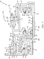
- the transmission 10 illustratively includes a mechanical clutch 12 as shown in Fig. 1 .
- the clutch 12 includes a first shaft 14, a second shaft 16, a primary (friction-cone) engagement system 18, and a secondary (splined) engagement system 20.
- Each of the primary and secondary engagement systems 18, 20 is configured to selectively transmit rotation from the first shaft 14 to the second shaft 16.
- the engagement systems 18, 20 provide redundant means for transmitting rotation from the first shaft 14 to the second shaft 16 so that in the event that one of the engagement systems 18, 20 fails connection of the first shaft 14 to the second shaft 16 is maintained.
- the primary (friction-cone) engagement system 18 is configured to synchronize rotation of the first and second shafts 14, 16 when partially engaged and to transmit rotation from the first shaft 14 to the second shaft 16 when fully engaged as shown in Fig. 3 . Rotation is transmitted from the first shaft 14 to the second shaft 16 by the primary engagement system 18 as the result of frictional contact between components of the primary engagement system 18.
- the primary engagement system 18 may therefore be said to be a frictional engagement system.
- the primary engagement system 18 has a first frustoconical engagement member 22 that is coupled for common rotation with the first shaft 14 as shown in Fig. 1 . Additionally, the primary engagement system 18 has a second frustoconical engagement member 24 that is coupled for common rotation with the second shaft 16. When the engagement members 22, 24 are brought into frictional contact with one another, rotation is transmitted from the first shaft 14 to the second shaft 16 by the primary engagement system 18.
- the second frustoconical engagement member 24 of the primary engagement system 18 is coupled to the second shaft 16 to slide relative thereto as shown in Fig. 1 .
- the second engagement member 24 is coupled to the second shaft 16 to slide relative thereto from a de-actuated position 30 (shown in Figs. 1-2 ) to an actuated position 32 (shown in Figs. 3-4 ).
- the second engagement member 24 is disengaged from the frustoconical engagement member 22 in the de-actuated position 30. As such, rotation is not transmitted from the first shaft 14 to the second shaft 16 by the primary engagement system 18 in the de-actuated position 30.
- the second engagement member 24 is engaged with the engagement member 22 in the actuated position 32 to synchronize rotation of the first and second shafts 14, 16. Rotation is therefore transmitted from the first shaft 14 to the second shaft 16 by the primary engagement system 18 in the actuated position 32.
- the secondary (splined) engagement system 20 is configured to lock the first shaft 14 and the second shaft 16 together for common rotation with one another as shown in Fig. 4 . Rotation is transmitted from the first shaft 14 to the second shaft 16 by the secondary engagement system 20 as the result of splined engagement between components of the engagement system 20.
- the secondary engagement system 20 may therefore be said to be a splined or fixed engagement system.
- the secondary engagement system 20 has first shaft splines 26 that are coupled to the first shaft 14 for movement therewith as shown in Fig. 1 . Additionally, the secondary engagement system 20 has second shaft splines 28 that are coupled to the second shaft 16 for movement therewith. When the first shaft splines 26 are brought into engagement with the second shaft splines 28, rotation is transmitted from the first shaft 14 to the second shaft 16 by the secondary engagement system 20.
- the second shaft splines 28 of the secondary engagement system 20 are illustratively mounted to the second shaft 16 to slide therewith as shown in Fig. 1 .
- the second shaft splines 28 are mounted to the second shaft 16 to slide therewith from a de-actuated position 34 (shown in Figs. 1-3 ) to an actuated position 36 (shown in Fig. 4 ).
- the second shaft splines 28 are disengaged from the first shaft splines 26 in the de-actuated position 34. As such, rotation is not transmitted from the first shaft 14 to the second shaft 16 by the secondary engagement system 20 in the de-actuated position 34.
- the second shaft splines 28 are engaged with the first shaft splines 26 in the actuated position 36 to lock the shafts 14, 16 together for common rotation with one another. Rotation is therefore transmitted from the first shaft 14 to the second shaft 16 by the secondary engagement system 20 in the actuated position 36.
- the first frustoconical engagement member 22, the first shaft 14, and the first shaft splines 26 are illustratively integrally formed with one another as shown in Fig. 1 .
- the splines 26 are arranged inward of the engagement member 22 in a radial direction indicated by arrow 12R.
- one or more of the frustoconical engagement member 22, the first shaft 14, and the first shaft splines 26 may be separately formed from the other of the engagement member 22, the shaft 14, and the splines 26.
- the engagement member 22 and the shaft 14 may be separately formed components.
- the engagement member 22 may be integrally formed with the shaft 14, and the splines 26 may be separately formed from the engagement member 22 and the shaft 14.
- the second frustoconical engagement member 24 is illustratively positioned outward in the radial direction indicated by arrow 12R of the first frustoconical engagement member 22 as shown in Fig. 1 .
- the second frustoconical engagement member 24 includes a frustoconical, internal engagement surface 25 that is configured to engage a frustoconical, external engagement surface 23 of the first frustoconical engagement member 22.
- the internal engagement surface 25 contacts the external engagement surface 23 such that the surfaces 23, 25 apply frictional forces to one another.
- the frictional forces synchronize rotation of the members 22, 24 and thus the respective shafts 14, 16, so that the rotational speeds of the shafts 14, 16 approach one another.
- the synchronized rotation of the shafts 14, 16 allows rotation from the shaft 14 to be transmitted to the shaft 16 by the primary engagement system 18.
- the primary engagement system 18 illustratively includes slide splines 29 that are coupled to the second frustoconical engagement member 24 for movement therewith as shown in Fig. 1 .
- the slide splines 29 are intermeshed with the second shaft splines 28 included in the second (splined) engagement system 20.
- the second engagement member 24 is coupled to the second shaft 16 for rotation therewith while being allowed to slide relative to the second shaft 16 from the de-actuated position 30 to the actuated position 32.
- the slide splines 29 are illustratively internal splines, but in other embodiments, the slide splines 29 may be external splines.
- the first shaft splines 26 of the secondary engagement system 20 are internal splines and the second shaft splines 28 are external splines as shown in Fig. 1 . In other embodiments, however, the splines 26 may be external splines, and the second splines 28 may be internal splines.
- the first shaft 14 is locked to the second shaft 16 so that the rotational speeds of the shafts 14, 16 are substantially the same. Locking of the shafts 14, 16 allows rotation from the shaft 14 to be transmitted to the shaft 16 by the secondary engagement system 20.
- the first shaft 14 and the first frustoconical engagement member 22 are illustratively coupled for common rotation with a drive shaft 33 as shown in Fig. 1 .
- the shaft 14 and the engagement member 22 are supported for rotation with the drive shaft 33 relative to a stationary element 56 by a bearing 35.
- the shaft 14 and the engagement member 22 are coupled to an inner race 37 of the bearing 35.
- the inner race 37 is coupled to an outer race 39 of the bearing 35 through a plurality of balls 41 (one of which is shown in Fig. 1 ) that are engaged with the inner and outer races 37, 39.
- the outer race 39 is coupled to the stationary element 56 by a fastener 43.
- the second shaft 16 and the second frustoconical engagement member 24 are illustratively coupled for common rotation with a driven shaft 45 as shown in Fig. 1 .
- the shaft 16 includes driven splines 47 that are configured to couple to the driven shaft 45.
- the driven splines 47 are illustratively internal splines that are positioned inward in the radial direction indicated by arrow 12R of the second shaft splines 28. In other embodiments, however, the driven splines 47 may be external splines.
- rotation from the drive shaft 33 is selectively transmitted by the primary and secondary engagement systems 18, 20 to the driven shaft 45 through the first and second shafts 14, 16 as suggested by Fig. 1 .
- rotation may be selectively transmitted by the engagement systems 18, 20 between the shafts 33, 45 in a different fashion.
- rotation from the shaft 45 may be selectively transmitted by the engagement systems 18, 20 to the shaft 33 through the shafts 14, 16.
- the primary and secondary engagement systems 18, 20 provide redundant engagement systems of the clutch 12 as suggested by Fig. 1 .
- the engagement system 20 may be used to transmit rotation from the drive shaft 33 to the driven shaft 45 through the first and second shafts 14, 16.
- the engagement system 18 may be used to transmit rotation from the shaft 33 to the shaft 45 through the shafts 14, 16.
- each of the primary and secondary engagement systems 18, 20 are hydraulically-actuated engagement systems as suggested by Fig. 1 .
- the clutch 12 is therefore illustratively embodied as a hydraulically-actuated clutch. In other embodiments, however, the clutch 12 may be embodied as a pneumatically-actuated clutch or an electromagnetically-actuated clutch.
- the hydraulically-actuated components of the engagement systems 18, 20 are described in greater detail below.
- the primary engagement system 18 illustratively includes a primary engagement system actuator 42, also referred to as a frictional engagement system actuator, as shown in Fig. 1 .
- the actuator 42 is configured to move in a direction indicated by arrow 42A in response to hydraulic fluid pressure applied to the actuator 42 as best seen in Figs. 2-4 .
- the actuator 42 is coupled to the second frustoconical engagement member 24 to move the member 24 from the de-actuated position 30 to the actuated position 32 in a direction indicated by arrow 24A as best seen in Figs. 2-4 .
- the primary engagement system actuator 42 is coupled to the second frustoconical engagement member 24 through a bearing 44 as shown in Fig. 1 .
- a portion 46 of the engagement system actuator 42 is coupled to an outer race 48 of the bearing 44 by a fastener 50.
- the outer race 48 is coupled to an inner race 52 of the bearing 44 through a plurality of balls 54 (one of which is shown in Fig. 1 ) that are engaged with the inner and outer races 52, 48.
- the inner race 52 is coupled directly to the engagement member 24.
- the bearing 44 supports the engagement member 24 for rotation relative to the engagement system actuator 42.
- the primary engagement system actuator 42 is engaged with stationary elements 56, 58 that are coupled to one another as shown in Fig. 1 .
- a portion 60 of the actuator 42 that is positioned outward of the portion 46 in the radial direction indicated by arrow 12R is engaged with the stationary element 56.
- a portion 62 of the actuator 42 that interconnects the portions 46, 60 and is positioned outward of the portion 46 in the radial direction indicated by arrow 12R is engaged with the element 58.
- Engagement of the portions 60, 62 with the elements 56, 58 constrains the actuator 42 against rotation with the second frustoconical engagement member 24.
- the portion 60 of the primary engagement system actuator 42 is received in a channel 64 that is cooperatively defined by the stationary elements 56, 58 as shown in Fig. 1 .
- a wall 66 of the portion 60 is spaced from the element 56 to define a fluid chamber 68 therebetween.
- a wall 70 of the portion 60 that is positioned opposite the wall 66 is spaced from the element 58 to define a fluid chamber 72 therebetween.
- Each of the chambers 68, 72 is positioned outward in the radial direction indicated by arrow 12R of the bearings 35, 44.
- a wall 74 of the portion 60 that interconnects the walls 66, 70 is engaged with the element 56.
- a wall 76 of the portion 60 that interconnects the walls 66, 70 and is positioned opposite the wall 74 is also engaged with the element 56.
- the fluid chamber 68 is fluidly coupled to a port 78 that is formed in the stationary element 56 as shown in Fig. 1 .
- the fluid chamber 72 is fluidly coupled to a port 80 that is formed in the stationary element 58.
- Hydraulic fluid delivered to the chamber 72 through the port 80 applies pressure to the primary engagement system actuator 42 to cause the actuator 42 to move in the direction indicated by arrow 42A.
- the second frustoconical engagement member 24 moves with the actuator 42 in the direction indicated by arrow 24A from the de-actuated position 30 toward the actuated position 32.
- Hydraulic fluid delivered to the chamber 68 through the port 78 applies pressure to the actuator 42 to cause the actuator 42 to move in a direction opposite to the direction indicated by arrow 42A.
- the engagement member 24 moves with the actuator 42 in a direction opposite to the direction indicated by arrow 24A from the position 32 toward the position 30.
- the secondary engagement system 20 illustratively includes a secondary engagement system actuator 82, also referred to as a fixed engagement system actuator, as shown in Fig. 1 .
- the actuator 82 is configured to move in a direction indicated by arrow 82A in response to hydraulic fluid pressure applied to the actuator 82 as best seen in Figs. 2-4 .
- the actuator 82 is coupled to the second shaft splines 28 to move the splines 28 from the de-actuated position 34 to the actuated position 36 in a direction indicated by arrow 28A as best seen in Figs. 2-4 .
- the secondary engagement system actuator 82 is coupled to the second shaft 16, and thus the second shaft splines 28, through a bearing 84 as shown in Fig. 1 .
- a portion 86 of the actuator 82 is coupled to an outer race 88 of the bearing 84 by a fastener 90.
- the outer race 88 is coupled to an inner race 92 of the bearing 84 through a plurality of balls 94 (one of which is shown in Fig. 1 ) that are engaged with the inner and outer races 92, 88.
- the inner race 92 is coupled directly to the shaft 16.
- the bearing 84 supports the shaft 16 for rotation relative to the actuator 82.
- the secondary engagement system actuator 82 is engaged with stationary elements 58, 61 that are coupled to one another by a fastener 63 as shown in Fig. 1 .
- a portion 96 of the actuator 82 that is positioned outward of the portion 86 in the radial direction indicated by arrow 12R is engaged with the element 58.
- a portion 98 of the actuator 82 that interconnects the portions 86, 96 and is positioned outward of the portion 86 in the radial direction indicated by arrow 12R is engaged with the element 61. Engagement of the portions 96, 98 with the elements 58, 61 constrains the actuator 82 against rotation with the second shaft 16.
- the portion 96 of the secondary engagement system actuator 82 is received in a channel 100 that is cooperatively defined by the stationary elements 58, 61 as shown in Fig. 1 .
- a wall 102 of the portion 96 is spaced from the element 58 to define a fluid chamber 104 therebetween.
- a wall 106 of the portion 96 that is positioned opposite the wall 102 is spaced from the element 61 to define a fluid chamber 108 therebetween.
- Each of the chambers 104, 108 is positioned outward in the radial direction indicated by arrow 12R of the bearings 35, 44, 84.
- a wall 110 of the portion 96 that interconnects the walls 102, 106 is engaged with the element 58.
- a wall 112 of the portion 96 that interconnects the walls 102, 106 and is positioned opposite the wall 110 is also engaged with the element 58.
- the fluid chamber 104 is fluidly coupled to a port 114 that is formed in the stationary element 58 as shown in Fig. 1 .
- the fluid chamber 108 is fluidly coupled to a port 116 that is formed in the stationary element 61.
- Hydraulic fluid delivered to the chamber 108 through the port 116 applies pressure to the secondary engagement system actuator 82 to cause the actuator 82 to move in the direction indicated by arrow 82A.
- the second shaft splines 28 move with the actuator 82 in the direction indicated by arrow 28A from the de-actuated position 34 toward the actuated position 36.
- Hydraulic fluid delivered to the chamber 104 through the port 114 applies pressure to the actuator 82 to cause the actuator 82 to move in a direction opposite to the direction indicated by arrow 82A.
- the splines 28 move with the actuator 82 in a direction opposite to the direction indicated by arrow 28A from the position 36 toward the position 34.
- the primary and secondary engagement system actuators 42, 82 are movable within their respective channels 64, 100 independently of one another as shown in Fig. 1 .
- the second frustoconical engagement member 24 is movable between the de-actuated and actuated positions 30, 32 independently of movement of the second shaft splines 28 between the de-actuated and actuated positions 34, 36.
- Components of each of the primary and secondary engagement systems 18, 20 may be constructed of metallic materials. Alternatively, components of each of the systems 18, 20 may be constructed of polymeric materials. In one example, components of each of the systems 18, 20 may be constructed of the polymeric material PEEK ® . In another example, components of each of the systems 18, 20 may be constructed of the polymeric material AURUM ® . Components of each of the systems 18, 20 may include nano-crystalline coatings deposited thereon, such as nano-crystalline coatings containing nickel or cobalt-based alloys.
- the transmission 10 illustratively includes a hydraulic fluid source 120 as shown in Fig. 1 .
- the fluid source 120 is fluidly coupled to the ports 78, 80, 114, 116. Hydraulic fluid supplied by the fluid source 120 is selectively delivered to the primary engagement system actuator 42 to cause the second frustoconical engagement member 24 to move from the de-actuated position 30 to the actuated position 32. Hydraulic fluid supplied by the fluid source 120 is selectively delivered to the secondary engagement system actuator 82 to cause the second shaft splines 28 to move from the de-actuated position 34 to the actuated position 36.
- the transmission 10 illustratively includes a controller 122 that is coupled to the fluid source 120 as shown in Fig. 1 .
- the controller 122 may be coupled to the fluid source 120 through one or more solenoid valves that are configured to deliver fluid from the fluid source 120 to each of the ports 78, 80, 114, 116 in response to electrical signals provided to the solenoid valve(s) by the controller 122.
- the solenoid valve(s) may be included in an electro-hydraulic control system of the transmission 10.
- the controller 122 includes a processor 124 and memory 126 coupled to the processor 124.
- the memory 126 includes instructions stored therein that are executable by the processor 124 to cause a number of activities to take place, as described in greater detail below with respect to operation of the transmission 10.
- the transmission 10 is illustratively operable in a plurality of operating modes 130.
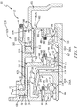
- one operating mode 132 shown in Fig. 2 rotation from the drive shaft 33, and thus the first shaft 14, is not transmitted to the second shaft 16, and thus the driven shaft 45.
- another operating mode 134 shown in Fig. 3 rotation from the drive shaft 33 is transmitted to the driven shaft 45 through the shafts 14, 16 by the primary engagement system 18.
- another operating mode 136 shown in Fig. 4 rotation from the drive shaft 33 is transmitted to the driven shaft 45 through the shafts 14, 16 by the primary and secondary engagement systems 18, 20.
- yet another operating mode 138 still shown in Fig. 5 rotation from the drive shaft 33 is transmitted to the driven shaft 45 through the shafts 14, 16 by the secondary engagement system 20.
- the transmission 10 is shown in the operating mode 132.
- the mode 132 though hydraulic fluid from the fluid source 120 is present in the fluid chamber 72, the hydraulic fluid has not been pressurized, and therefore the primary engagement system actuator 42 has not moved in the direction indicated by arrow 42A. As a result, the second frustoconical engagement member 24 is in the de-actuated position 30. Additionally, in the mode 132, though hydraulic fluid from the source 120 is present in the fluid chamber 108, the hydraulic fluid has not been pressurized, and therefore the secondary engagement system actuator 82 has not moved in the direction indicated by arrow 82A. Consequently, the second shaft splines 28 are in the de-actuated position 34.
- the transmission 10 is shown in the operating mode 134.
- the instructions stored in the memory 126 are executed by the processor 124 to pressurized hydraulic fluid from the fluid source 120 present in the chamber 72.
- Fluid pressure applied to the primary engagement system actuator 42 in the chamber 72 causes the actuator 42 to move in the direction indicated by arrow 42A, thereby causing the second frustoconical engagement member 24 to move in the direction indicated by arrow 24A to the actuated position 32.
- the hydraulic fluid from the source 120 present in the chamber 108 has not been pressurized, and therefore the secondary engagement system actuator 82 has not moved in the direction indicated by arrow 82A. Consequently, the second shaft splines 28 are in the de-actuated position 34.
- the transmission 10 is shown in the operating mode 136.
- the second frustoconical engagement member 24 remains in the actuated position 32 attained in the operating mode 134.
- the instructions stored in the memory 126 are executed by the processor 124 to pressurize hydraulic fluid from the fluid source 120 present in the fluid chamber 108 in response to movement of the member 24 to the position 32.
- Fluid pressure applied to the secondary engagement system actuator 82 in the chamber 108 causes the actuator 82 to move in the direction indicated by arrow 82A, thereby causing the second shaft splines 28 to move in the direction indicated by arrow 28A to the actuated position 36.
- the instructions stored in the memory 126 are executed by the processor 124 to cause hydraulic fluid to be expelled from the fluid chamber 72 in response to movement of the second shaft splines 28 to the actuated position 36 as shown in Fig. 4 .
- hydraulic fluid contained in the chamber 72 may remain therein when the splines 28 attain the position 36.
- the transmission 10 is shown in the operating mode 138.
- the second shaft splines 28 remain in the actuated position 36 attained in the operating mode 136.
- the second frustoconical engagement member 24 has moved in the direction opposite to the direction indicated by arrow 24A from the actuated position 32 attained in Fig. 4 to the de-actuated position 30.
- the method includes actuating the primary engagement system actuator 42 to engage the second frustoconical engagement member 24 with the first frustoconical engagement member 22 to synchronize rotation of the first and second shafts 14, 16.
- the method further includes actuating the secondary engagement system actuator 82 to engage the second shaft splines 28 with the first shaft splines 26 to lock the shafts 14, 16 together upon synchronizing rotation of the shafts 14, 16.
- the method further still includes de-actuating the actuator 42 to disengage the engagement member 24 from the engagement member 22 upon locking the shafts 14, 16 together.
- the transmission 10 may include sensors that are configured to provide feedback to the controller 122 in each of the operating modes 130. Specifically, the sensors may provide electrical input to the controller 122 indicative of the positional state of components of each of the primary and secondary engagement systems 18, 20 in each mode 130.
- One sensor may be used to monitor the position of the primary engagement system actuator 42 within the channel 64 in each mode 130.
- Another sensor may be used to monitor the position of the secondary engagement system actuator 82 within the channel 100 in each mode 130.
- Yet another sensor may be used to monitor engagement between the first and second frustoconical engagement members 22, 24 in each mode 130.
- Yet another sensor still may be used to monitor engagement between the first and second shaft splines 26, 28 in each mode 130.
- the sensors may be embodied as linear position sensors.
- the sensors may be embodied as linear variable differential transformers (LVDTs), or the like.
- the sensors may also be embodied as switches such as, for example, reed switches, or the like.
- feedback provided to the controller 122 from the sensors may be used to detect failure of the primary and second engagement systems 18, 20 in operation of the transmission 10.
- sensor input indicative of a failure of the primary engagement system actuator 42 may cause the controller 122 to direct movement of the secondary engagement system actuator 82 to engage the second shaft splines 28 with the first shaft splines 26.
- sensor input indicative of a failure of the actuator 82 may cause the controller 122 to direct movement of the actuator 42 to engage the second frustoconical engagement member 24 with the first frustoconical engagement member 22.
- a portion 262 of a primary engagement system actuator 242 of the clutch 212 includes an anti-rotation feature 263 as shown in Fig. 6 .
- the anti-rotation feature 263 is illustratively embodied as a projection or spline that is configured to engage a complementary feature formed in a stationary element 258. Engagement of the anti-rotation feature 263 and the complementary feature constrains the actuator 242 against rotation relative to the element 258 with a second frustoconical engagement member 224.
- stationary elements 256, 258 of the clutch 212 are engaged with a stop 265 that is received by a cutout 267 formed in the element 256 as shown in Fig. 6 .
- the stop 265 is positioned in a channel 264 that is cooperatively defined by the elements 256, 258.
- the primary engagement system actuator 242 is also positioned in the channel 264, and the stop 265 abuts the elements 256, 258 and the portion 262 of the actuator 242.
- a fluid chamber 272 is defined between the stop 265 and a portion 260 of the actuator 242.
- the stationary element 258 of the clutch 212 is coupled by a fastener 269 to a stop 271 that is received by a cutout 273 formed in the element 258 as shown in Fig. 6 .
- the stop 271 is positioned in a channel 300 that is defined by the element 258.
- a secondary engagement system actuator 282 is also positioned in the channel 300, and the stop 271 abuts the element 258 and the actuator 282.
- a fluid chamber 304 is defined between the stop 271 and a portion 296 of the actuator 282.
- the size of the secondary engagement system actuator 282 of the clutch 212 in a radial direction indicated by 212R illustratively differs from the size of the actuator 82 of the clutch 12 in a radial direction indicated by 12R as shown in Fig. 6 .
- the actuator 282 is smaller in the radial direction indicated by 212R than the actuator 82 in the radial direction indicated by 12R.
- the positioning of the channel 300 relative to bearings 235, 244, 284 of the clutch 212 illustratively differs from the positioning of the channel 100 relative to the bearings 35, 44, 84 of the clutch 112 as shown in Fig. 6 .
- the channel 100 is positioned outward of the bearings 35, 44, 84 in the direction indicated by arrow 12R
- the channel 300 is not positioned outward of the bearings 235, 244, 284 in the direction indicated by arrow 212R. Rather, the channel 300 is positioned substantially in line with the bearings 235, 244, 284 in the direction indicated by arrow 212R.
- the number of stationary elements included in the clutch 212 illustratively differs from the number of stationary elements included in the clutch 112 as shown in Fig. 6 . Whereas the clutch 112 includes the stationary elements 56, 58, 61, the clutch 212 includes only the stationary elements 256, 258. Thus, the number of stationary elements included in the clutch 212 is less than the number of stationary elements included in the clutch 112.
- the package size of the clutch 212 illustratively differs from the package size of the clutch 12 as shown in Fig. 6 .
- the package size of the clutch 212 is smaller than the package size of the clutch 12.
- the clutch 212 is smaller in an axial direction indicated by arrow 212A than the clutch 12 in an axial direction indicated by arrow 12A, and the clutch 212 is smaller in the radial direction indicated by arrow 212R than the clutch 12 in the radial direction indicated arrow 12R.
- the present disclosure is related to providing a lightweight, low-profile clutch with redundant engaging capabilities.
- the clutches disclosed herein may provide redundancy in a package that may weigh about 100 pounds.
- the clutch such as the clutches 12, 212 disclosed herein, may consist of a drive cone that may contain an internal spline, such as the members 22, 222 containing respective splines 26, 226.
- the clutch may also include a driven cone that may be connected through a bearing to a non-rotating primary engagement piston and may also slide along a spline connection with an internal engagement shaft, such as the members 24, 224 that are connected through bearings 44, 244 to actuators 42, 242 and slide relative to shafts 16, 216 via splines 29, 229.
- the clutch may also include a non-rotating locking piston that may be also connected through a bearing to the engagement shaft, such as the actuators 82, 282 connected through bearings 84, 284 to shafts 16, 216.
- the engagement shaft may have an internal spline that may be engaged to the driven shaft, such as the driven splines 47, 247.
- the drive cone may rotate constantly when it is coupled to the drive shaft, such as the drive shaft 33.
- the driven shaft, the driven cone, and the engagement shaft may rotate at a non-synchronous speed to the drive shaft and the drive cone prior to engagement.
- hydraulic pressure may be applied to an aft side of the primary engagement piston, such as the walls 70, 270 of the actuators 42, 242.
- the driven cone may translate forward to engage the drive cone, which may in turn synchronize the drive shaft and the driven shaft, like the synchronization associated with the primary engagement systems 18, 218.
- Hydraulic pressure may then be applied to the aft side of the locking piston, such as the walls 106, 306 of the actuators 82, 282.
- the engagement shaft may translate forward to engage the inner spline of the drive cone, which may in turn lock the driven shaft to the drive shaft, like the locking associated with the secondary engagement systems 20, 220. Pressure may then be relieved from the primary engagement piston.
- a secondary method of engagement may be employed in which the engagement shaft may directly engage the drive cone spline. This may be accomplished through repeated actuation of the lock piston if necessary, in order to achieve suitable spline alignment. Feedback of spline engagement and piston movement may be provided to a control unit through the use of a reed switch or LVDT.
- composite materials may also be possible to incorporate composite materials into the concept disclosed herein, along with nano-crystalline coatings. Such materials may ultimately have the potential to not only reduce weight of the clutch unit, but also reduce cost.
Landscapes
- Engineering & Computer Science (AREA)
- General Engineering & Computer Science (AREA)
- Mechanical Engineering (AREA)
- Physics & Mathematics (AREA)
- Fluid Mechanics (AREA)
- Mechanical Operated Clutches (AREA)
- Hydraulic Clutches, Magnetic Clutches, Fluid Clutches, And Fluid Joints (AREA)
Abstract
Description
- The present disclosure relates generally to clutches, and more specifically to hydraulically-actuated clutches.
- Hydraulically-actuated clutches are often used to transmit rotation from one component (e.g., a driving component) to another component (e.g., a driven component). The size and materials of construction of some hydraulically-actuated clutches may limit their desirability. Additionally, the desirability of hydraulically-actuated clutches that provide only one engagement system to transmit rotation from one component to another component may be limited.
- The present disclosure may comprise one or more of the following features and combinations thereof.
- According to one aspect of the present disclosure, a clutch may comprise a first shaft, a second shaft, a primary engagement system, and a secondary engagement system. The primary engagement system may be configured to selectively transmit rotation from the first shaft to the second shaft. The primary engagement system may include a first frustoconical engagement member coupled for common rotation with the first shaft, and a second frustoconical engagement member coupled for common rotation with the second shaft. The secondary engagement system may be configured to selectively transmit rotation from the first shaft to the second shaft. The secondary engagement system may include first shaft splines coupled to the first shaft for movement therewith, and second shaft splines coupled to the second shaft for movement therewith. The second frustoconical engagement member of the primary engagement system may be coupled to the second shaft to slide relative to the second shaft from a first position disengaged from the first frustoconical engagement member to a second position engaged with the first frustoconical engagement member.
- In some embodiments, the second shaft splines may be mounted to slide with the second shaft from a first position disengaged from the first shaft splines to a second position engaged with the first shaft splines. Additionally, in some embodiments, the primary engagement system may include slide splines coupled to the second frustoconical engagement member for movement therewith. The slide splines may be intermeshed with the second shaft splines to couple the second frustoconical engagement member to the second shaft for rotation therewith while allowing the second frustoconical engagement member to slide relative to the second shaft. The second frustoconical engagement member may form an internal engagement surface that contacts the first frustoconical engagement member when the second frustoconical engagement member is in the second position.
- In some embodiments, the first shaft splines may be internal splines and the second shaft splines may be external splines. The primary engagement system may include internal slide splines coupled to the second frustoconical engagement member for movement therewith. The internal slide splines may be intermeshed with the second shaft splines to couple the second frustoconical engagement member to the second shaft for rotation therewith while allowing the second frustoconical engagement member to slide relative to the second shaft.
- In some embodiments, the first frustoconical engagement member may be integrally formed with the first shaft. Additionally, in some embodiments, the first frustoconical engagement member, the first shaft, and the first shaft splines may be integrally formed with one another.
- According to another aspect of the present disclosure, a clutch may comprise a first shaft, a second shaft, a primary engagement system, and a secondary engagement system. The primary engagement system may be configured to selectively transmit rotation from the first shaft to the second shaft. The primary engagement system may include a first frustoconical engagement member coupled for common rotation with the first shaft, a second frustoconical engagement member coupled for common rotation with the second shaft, and a primary engagement system actuator coupled to the second frustoconical engagement member. The primary engagement system actuator may be configured to move the second frustoconical engagement member from a de-actuated position disengaged from the first frustoconical engagement member to an actuated position engaged with the first frustoconical engagement member. The secondary engagement system may be configured to selectively transmit rotation from the first shaft to the second shaft. The secondary engagement system may include first shaft splines coupled to the first shaft for movement therewith, second shaft splines coupled to the second shaft for movement therewith, and a secondary engagement system actuator coupled to the second shaft. The secondary engagement system actuator may be configured to move the second shaft splines from a de-actuated position disengaged from the first shaft splines to an actuated position engaged with the first shaft splines.
- In some embodiments, the primary engagement system actuator and the secondary engagement system actuator may be independent of one another so that the second frustoconical engagement member and the second shaft splines are movable between their respective de-actuated and actuated positions independently of one another. Additionally, in some embodiments, the first frustoconical engagement member may be integrally formed with the first shaft, and the first shaft splines may be arranged radially inward of the first frustoconical engagement member.
- In some embodiments, the second frustoconical engagement member may be coupled to the second shaft to slide relative to the second shaft. The primary engagement system may include slide splines coupled to the second frustoconical engagement member for movement therewith. The slide splines may be intermeshed with the second shaft splines to couple the second frustoconical engagement member to the second shaft for rotation therewith while allowing the second frustoconical engagement member to slide relative to the second shaft. Additionally, in some embodiments, the first shaft splines may be internal splines and the second shaft splines may be external splines. The primary engagement system may include internal slide splines coupled to the second frustoconical engagement member for movement therewith. The internal slide splines may be intermeshed with the second shaft splines to couple the second frustoconical engagement member to the second shaft for rotation therewith while allowing the second frustoconical engagement member to slide relative to the second shaft.
- According to yet another aspect of the present disclosure, a transmission may comprise a source of hydraulic fluid, a first shaft, a second shaft, a frictional engagement system, a fixed engagement system, and a controller. The frictional engagement system may be configured to selectively transmit rotation from the first shaft to the second shaft. The frictional engagement system may include a first engagement member coupled for common rotation with the first shaft, a second engagement member coupled for common rotation with the second shaft, and a frictional engagement system actuator coupled to the second engagement member. The frictional engagement system actuator may be configured to move the second engagement member from a de-actuated position disengaged from the first engagement member to an actuated position engaged with the first engagement member. The fixed engagement system may be configured to selectively transmit rotation from the first shaft to the second shaft. The fixed engagement system may include first shaft splines coupled to the first shaft for movement therewith, second shaft splines coupled to the second shaft for movement therewith, and a fixed engagement system actuator coupled to the second shaft. The fixed engagement system actuator may be configured to move the second shaft splines from a de-actuated position disengaged from the first shaft splines to an actuated position engaged with the first shaft splines. The controller may include a processor and memory. The memory may have instructions stored therein that are executable by the processor to pressurize hydraulic fluid supplied by the source to cause at least one of the (i) the frictional engagement system actuator to move from the de-actuated position to the actuated position and (ii) the fixed engagement system actuator to move from the de-actuated position to the actuated position.
- In some embodiments, the memory may include instructions that are executable by the processor to pressurize hydraulic fluid supplied by the source to cause the frictional engagement system actuator to move from the de-actuated position to the actuated position to synchronize rotation of the first and second shafts. The memory may also include instructions that are executable by the processor to pressurize hydraulic fluid supplied by the source to cause the fixed engagement system actuator to move from the de-actuated position to the actuated position to lock the first and second shafts together upon synchronization of the first and second shafts after movement of the second engagement member to the actuated position. The memory may include instructions that are executable by the processor to pressurize hydraulic fluid supplied by the source to cause the frictional engagement system actuator to move from the actuated position to the de-actuated position after movement of the second shaft splines to the actuated position.
- In some embodiments, the frictional engagement system actuator may be constrained against rotation with the second engagement member, and the fixed engagement system actuator may be constrained against rotation with the second shaft. Additionally, in some embodiments, the first engagement member may comprise a first frustoconical engagement member, and the second engagement member may comprise a second frustoconical engagement member
- These and other features of the present disclosure will become more apparent from the following description of the illustrative embodiments.
-
-
Fig. 1 is a cross-sectional view of a clutch included in a transmission adapted for use in a gas turbine engine that includes a controller and a fluid source shown in diagrammatic form; -
Fig. 2 is a cross-sectional view of the clutch ofFig. 1 showing a primary (friction-cone) engagement system of the clutch in a disengaged state in which rotation is not transmitted from a first shaft to a second shaft by frustoconical engagement members coupled to the first and second shafts and a secondary (splined) engagement system of the clutch in a disengaged state in which rotation is not transmitted from the first shaft to the second shaft by splines coupled to the first and second shafts; -
Fig. 3 is a cross-sectional view of the clutch ofFig. 1 showing the secondary (splined) engagement system in the disengaged state and the primary (friction-cone) engagement system in an engaged state in which rotation is transmitted from the first shaft to the second shaft by frustoconical engagement members included in the primary engagement system; -
Fig. 4 is a cross-sectional view of the clutch ofFig. 1 showing the primary (friction-cone) engagement system in the engaged state and the secondary (splined) engagement system in an engaged state in which rotation is transmitted from the first shaft to the second shaft by splines included in the secondary engagement system; -
Fig. 5 is a cross-sectional view of the clutch ofFig. 1 showing the primary (friction-cone) engagement system in the disengaged state and the secondary (splined) engagement system in the engaged state; and -
Fig. 6 is a cross-sectional view of another clutch included in a second transmission adapted for use in a gas turbine engine showing that the clutch includes a primary (friction-cone) engagement system and a secondary (splined) engagement system. - For the purposes of promoting an understanding of the principles of the disclosure, reference will now be made to a number of illustrative embodiments illustrated in the drawings and specific language will be used to describe the same.
- Referring now to
Fig. 1 , atransmission 10 configured to selectively transmit rotation from one component to another component is shown. In the illustrative embodiment, thetransmission 10 is configured for use in a gas turbine engine. In other embodiments, however, thetransmission 10 may be configured for use in other applications. - The
transmission 10 illustratively includes a mechanical clutch 12 as shown inFig. 1 . The clutch 12 includes afirst shaft 14, asecond shaft 16, a primary (friction-cone)engagement system 18, and a secondary (splined)engagement system 20. Each of the primary andsecondary engagement systems first shaft 14 to thesecond shaft 16. In this way, theengagement systems first shaft 14 to thesecond shaft 16 so that in the event that one of theengagement systems first shaft 14 to thesecond shaft 16 is maintained. - The primary (friction-cone)
engagement system 18 is configured to synchronize rotation of the first andsecond shafts first shaft 14 to thesecond shaft 16 when fully engaged as shown inFig. 3 . Rotation is transmitted from thefirst shaft 14 to thesecond shaft 16 by theprimary engagement system 18 as the result of frictional contact between components of theprimary engagement system 18. Theprimary engagement system 18 may therefore be said to be a frictional engagement system. - The
primary engagement system 18 has a firstfrustoconical engagement member 22 that is coupled for common rotation with thefirst shaft 14 as shown inFig. 1 . Additionally, theprimary engagement system 18 has a secondfrustoconical engagement member 24 that is coupled for common rotation with thesecond shaft 16. When theengagement members first shaft 14 to thesecond shaft 16 by theprimary engagement system 18. - The second
frustoconical engagement member 24 of theprimary engagement system 18 is coupled to thesecond shaft 16 to slide relative thereto as shown inFig. 1 . Specifically, thesecond engagement member 24 is coupled to thesecond shaft 16 to slide relative thereto from a de-actuated position 30 (shown inFigs. 1-2 ) to an actuated position 32 (shown inFigs. 3-4 ). Thesecond engagement member 24 is disengaged from thefrustoconical engagement member 22 in thede-actuated position 30. As such, rotation is not transmitted from thefirst shaft 14 to thesecond shaft 16 by theprimary engagement system 18 in thede-actuated position 30. In contrast, thesecond engagement member 24 is engaged with theengagement member 22 in the actuatedposition 32 to synchronize rotation of the first andsecond shafts first shaft 14 to thesecond shaft 16 by theprimary engagement system 18 in the actuatedposition 32. - The secondary (splined)
engagement system 20 is configured to lock thefirst shaft 14 and thesecond shaft 16 together for common rotation with one another as shown inFig. 4 . Rotation is transmitted from thefirst shaft 14 to thesecond shaft 16 by thesecondary engagement system 20 as the result of splined engagement between components of theengagement system 20. Thesecondary engagement system 20 may therefore be said to be a splined or fixed engagement system. - The
secondary engagement system 20 has first shaft splines 26 that are coupled to thefirst shaft 14 for movement therewith as shown inFig. 1 . Additionally, thesecondary engagement system 20 has second shaft splines 28 that are coupled to thesecond shaft 16 for movement therewith. When the first shaft splines 26 are brought into engagement with the second shaft splines 28, rotation is transmitted from thefirst shaft 14 to thesecond shaft 16 by thesecondary engagement system 20. - The second shaft splines 28 of the
secondary engagement system 20 are illustratively mounted to thesecond shaft 16 to slide therewith as shown inFig. 1 . Specifically, the second shaft splines 28 are mounted to thesecond shaft 16 to slide therewith from a de-actuated position 34 (shown inFigs. 1-3 ) to an actuated position 36 (shown inFig. 4 ). The second shaft splines 28 are disengaged from the first shaft splines 26 in thede-actuated position 34. As such, rotation is not transmitted from thefirst shaft 14 to thesecond shaft 16 by thesecondary engagement system 20 in thede-actuated position 34. In contrast, the second shaft splines 28 are engaged with the first shaft splines 26 in the actuatedposition 36 to lock theshafts first shaft 14 to thesecond shaft 16 by thesecondary engagement system 20 in the actuatedposition 36. - The first
frustoconical engagement member 22, thefirst shaft 14, and the first shaft splines 26 are illustratively integrally formed with one another as shown inFig. 1 . Thesplines 26 are arranged inward of theengagement member 22 in a radial direction indicated byarrow 12R. - In other embodiments, however, one or more of the
frustoconical engagement member 22, thefirst shaft 14, and the first shaft splines 26 may be separately formed from the other of theengagement member 22, theshaft 14, and thesplines 26. In one example, theengagement member 22 and theshaft 14 may be separately formed components. In another example, theengagement member 22 may be integrally formed with theshaft 14, and thesplines 26 may be separately formed from theengagement member 22 and theshaft 14. - The second
frustoconical engagement member 24 is illustratively positioned outward in the radial direction indicated byarrow 12R of the firstfrustoconical engagement member 22 as shown inFig. 1 . The secondfrustoconical engagement member 24 includes a frustoconical,internal engagement surface 25 that is configured to engage a frustoconical,external engagement surface 23 of the firstfrustoconical engagement member 22. When thesecond engagement member 24 is in the actuatedposition 32, theinternal engagement surface 25 contacts theexternal engagement surface 23 such that thesurfaces members respective shafts shafts shafts shaft 14 to be transmitted to theshaft 16 by theprimary engagement system 18. - The
primary engagement system 18 illustratively includes slide splines 29 that are coupled to the secondfrustoconical engagement member 24 for movement therewith as shown inFig. 1 . As the second ;engagement member 24 moves from thede-actuated position 30 to the actuatedposition 32, the slide splines 29 are intermeshed with the second shaft splines 28 included in the second (splined)engagement system 20. In this way, thesecond engagement member 24 is coupled to thesecond shaft 16 for rotation therewith while being allowed to slide relative to thesecond shaft 16 from thede-actuated position 30 to the actuatedposition 32. The slide splines 29 are illustratively internal splines, but in other embodiments, the slide splines 29 may be external splines. - In the illustrative embodiment, the first shaft splines 26 of the
secondary engagement system 20 are internal splines and the second shaft splines 28 are external splines as shown inFig. 1 . In other embodiments, however, thesplines 26 may be external splines, and thesecond splines 28 may be internal splines. When thesplines 28 are engaged with thesplines 26 in the actuatedposition 36, thefirst shaft 14 is locked to thesecond shaft 16 so that the rotational speeds of theshafts shafts shaft 14 to be transmitted to theshaft 16 by thesecondary engagement system 20. - The
first shaft 14 and the firstfrustoconical engagement member 22 are illustratively coupled for common rotation with adrive shaft 33 as shown inFig. 1 . Theshaft 14 and theengagement member 22 are supported for rotation with thedrive shaft 33 relative to astationary element 56 by abearing 35. Theshaft 14 and theengagement member 22 are coupled to aninner race 37 of thebearing 35. Theinner race 37 is coupled to anouter race 39 of thebearing 35 through a plurality of balls 41 (one of which is shown inFig. 1 ) that are engaged with the inner andouter races outer race 39 is coupled to thestationary element 56 by afastener 43. - The
second shaft 16 and the secondfrustoconical engagement member 24 are illustratively coupled for common rotation with a drivenshaft 45 as shown inFig. 1 . Theshaft 16 includes drivensplines 47 that are configured to couple to the drivenshaft 45. The driven splines 47 are illustratively internal splines that are positioned inward in the radial direction indicated byarrow 12R of the second shaft splines 28. In other embodiments, however, the drivensplines 47 may be external splines. - In the illustrative embodiment, rotation from the
drive shaft 33 is selectively transmitted by the primary andsecondary engagement systems shaft 45 through the first andsecond shafts Fig. 1 . In other embodiments, however, rotation may be selectively transmitted by theengagement systems shafts shaft 45 may be selectively transmitted by theengagement systems shaft 33 through theshafts - The primary and
secondary engagement systems Fig. 1 . In the event of a failure of theengagement system 18, theengagement system 20 may be used to transmit rotation from thedrive shaft 33 to the drivenshaft 45 through the first andsecond shafts engagement system 20, theengagement system 18 may be used to transmit rotation from theshaft 33 to theshaft 45 through theshafts - In the illustrative embodiment, each of the primary and
secondary engagement systems Fig. 1 . The clutch 12 is therefore illustratively embodied as a hydraulically-actuated clutch. In other embodiments, however, the clutch 12 may be embodied as a pneumatically-actuated clutch or an electromagnetically-actuated clutch. The hydraulically-actuated components of theengagement systems - The
primary engagement system 18 illustratively includes a primaryengagement system actuator 42, also referred to as a frictional engagement system actuator, as shown inFig. 1 . Theactuator 42 is configured to move in a direction indicated byarrow 42A in response to hydraulic fluid pressure applied to theactuator 42 as best seen inFigs. 2-4 . Theactuator 42 is coupled to the secondfrustoconical engagement member 24 to move themember 24 from thede-actuated position 30 to the actuatedposition 32 in a direction indicated byarrow 24A as best seen inFigs. 2-4 . - The primary
engagement system actuator 42 is coupled to the secondfrustoconical engagement member 24 through abearing 44 as shown inFig. 1 . Aportion 46 of theengagement system actuator 42 is coupled to anouter race 48 of thebearing 44 by afastener 50. Theouter race 48 is coupled to aninner race 52 of thebearing 44 through a plurality of balls 54 (one of which is shown inFig. 1 ) that are engaged with the inner andouter races inner race 52 is coupled directly to theengagement member 24. Thebearing 44 supports theengagement member 24 for rotation relative to theengagement system actuator 42. - The primary
engagement system actuator 42 is engaged withstationary elements Fig. 1 . Aportion 60 of theactuator 42 that is positioned outward of theportion 46 in the radial direction indicated byarrow 12R is engaged with thestationary element 56. Aportion 62 of theactuator 42 that interconnects theportions portion 46 in the radial direction indicated byarrow 12R is engaged with theelement 58. Engagement of theportions elements actuator 42 against rotation with the secondfrustoconical engagement member 24. - The
portion 60 of the primaryengagement system actuator 42 is received in achannel 64 that is cooperatively defined by thestationary elements Fig. 1 . Awall 66 of theportion 60 is spaced from theelement 56 to define afluid chamber 68 therebetween. Awall 70 of theportion 60 that is positioned opposite thewall 66 is spaced from theelement 58 to define afluid chamber 72 therebetween. Each of thechambers arrow 12R of thebearings wall 74 of theportion 60 that interconnects thewalls element 56. Awall 76 of theportion 60 that interconnects thewalls wall 74 is also engaged with theelement 56. - As best seen in
Figs. 2-3 , engagement of thewalls stationary element 56 guides movement of the primaryengagement system actuator 42 within thechannel 64. As theactuator 42 moves in the direction indicated byarrow 42A (seeFig. 3 ), the secondfrustoconical engagement member 24 moves in the direction indicated byarrow 24A from thede-actuated position 30 toward the actuatedposition 32. When theactuator 42 is constrained against further movement in the direction indicated byarrow 42A (seeFig. 3 ), theengagement member 42 is in the actuatedposition 32. - The
fluid chamber 68 is fluidly coupled to aport 78 that is formed in thestationary element 56 as shown inFig. 1 . Thefluid chamber 72 is fluidly coupled to aport 80 that is formed in thestationary element 58. Hydraulic fluid delivered to thechamber 72 through theport 80 applies pressure to the primary engagement system actuator 42 to cause theactuator 42 to move in the direction indicated byarrow 42A. At the same time, the secondfrustoconical engagement member 24 moves with theactuator 42 in the direction indicated byarrow 24A from thede-actuated position 30 toward the actuatedposition 32. Hydraulic fluid delivered to thechamber 68 through theport 78 applies pressure to theactuator 42 to cause theactuator 42 to move in a direction opposite to the direction indicated byarrow 42A. As a result, theengagement member 24 moves with theactuator 42 in a direction opposite to the direction indicated byarrow 24A from theposition 32 toward theposition 30. - The
secondary engagement system 20 illustratively includes a secondaryengagement system actuator 82, also referred to as a fixed engagement system actuator, as shown inFig. 1 . Theactuator 82 is configured to move in a direction indicated byarrow 82A in response to hydraulic fluid pressure applied to theactuator 82 as best seen inFigs. 2-4 . Theactuator 82 is coupled to the second shaft splines 28 to move thesplines 28 from thede-actuated position 34 to the actuatedposition 36 in a direction indicated byarrow 28A as best seen inFigs. 2-4 . - The secondary
engagement system actuator 82 is coupled to thesecond shaft 16, and thus the second shaft splines 28, through abearing 84 as shown inFig. 1 . Aportion 86 of theactuator 82 is coupled to anouter race 88 of thebearing 84 by afastener 90. Theouter race 88 is coupled to aninner race 92 of thebearing 84 through a plurality of balls 94 (one of which is shown inFig. 1 ) that are engaged with the inner andouter races inner race 92 is coupled directly to theshaft 16. Thebearing 84 supports theshaft 16 for rotation relative to theactuator 82. - The secondary
engagement system actuator 82 is engaged withstationary elements fastener 63 as shown inFig. 1 . Aportion 96 of theactuator 82 that is positioned outward of theportion 86 in the radial direction indicated byarrow 12R is engaged with theelement 58. Aportion 98 of theactuator 82 that interconnects theportions portion 86 in the radial direction indicated byarrow 12R is engaged with theelement 61. Engagement of theportions elements actuator 82 against rotation with thesecond shaft 16. - The
portion 96 of the secondaryengagement system actuator 82 is received in achannel 100 that is cooperatively defined by thestationary elements Fig. 1 . Awall 102 of theportion 96 is spaced from theelement 58 to define afluid chamber 104 therebetween. Awall 106 of theportion 96 that is positioned opposite thewall 102 is spaced from theelement 61 to define afluid chamber 108 therebetween. Each of thechambers arrow 12R of thebearings wall 110 of theportion 96 that interconnects thewalls element 58. Awall 112 of theportion 96 that interconnects thewalls wall 110 is also engaged with theelement 58. - As best seen in
Figs. 3-4 , engagement of thewalls stationary element 58 guides movement of the secondaryengagement system actuator 82 within thechannel 100. As theactuator 82 moves in the direction indicated byarrow 82A (seeFig. 4 ), the second shaft splines 28 move in the direction indicated byarrow 28A from thede-actuated position 34 toward the actuatedposition 36. When theactuator 82 is constrained against further movement in the direction indicated byarrow 82A (seeFig. 4 ), thesplines 28 are in the actuatedposition 36. - The
fluid chamber 104 is fluidly coupled to aport 114 that is formed in thestationary element 58 as shown inFig. 1 . Thefluid chamber 108 is fluidly coupled to aport 116 that is formed in thestationary element 61. Hydraulic fluid delivered to thechamber 108 through theport 116 applies pressure to the secondary engagement system actuator 82 to cause theactuator 82 to move in the direction indicated byarrow 82A. At the same time, the second shaft splines 28 move with theactuator 82 in the direction indicated byarrow 28A from thede-actuated position 34 toward the actuatedposition 36. Hydraulic fluid delivered to thechamber 104 through theport 114 applies pressure to theactuator 82 to cause theactuator 82 to move in a direction opposite to the direction indicated byarrow 82A. As a result, thesplines 28 move with theactuator 82 in a direction opposite to the direction indicated byarrow 28A from theposition 36 toward theposition 34. - The primary and secondary engagement system actuators 42, 82 are movable within their
respective channels Fig. 1 . As such, the secondfrustoconical engagement member 24 is movable between the de-actuated and actuatedpositions positions - Components of each of the primary and
secondary engagement systems systems systems systems systems - The
transmission 10 illustratively includes a hydraulicfluid source 120 as shown inFig. 1 . Thefluid source 120 is fluidly coupled to theports fluid source 120 is selectively delivered to the primary engagement system actuator 42 to cause the secondfrustoconical engagement member 24 to move from thede-actuated position 30 to the actuatedposition 32. Hydraulic fluid supplied by thefluid source 120 is selectively delivered to the secondary engagement system actuator 82 to cause the second shaft splines 28 to move from thede-actuated position 34 to the actuatedposition 36. - The
transmission 10 illustratively includes acontroller 122 that is coupled to thefluid source 120 as shown inFig. 1 . Thecontroller 122 may be coupled to thefluid source 120 through one or more solenoid valves that are configured to deliver fluid from thefluid source 120 to each of theports controller 122. The solenoid valve(s) may be included in an electro-hydraulic control system of thetransmission 10. - The
controller 122 includes aprocessor 124 andmemory 126 coupled to theprocessor 124. Thememory 126 includes instructions stored therein that are executable by theprocessor 124 to cause a number of activities to take place, as described in greater detail below with respect to operation of thetransmission 10. - Referring now to
Figs. 2-5 , operation of thetransmission 10 will now be described. Thetransmission 10 is illustratively operable in a plurality of operatingmodes 130. In oneoperating mode 132 shown inFig. 2 , rotation from thedrive shaft 33, and thus thefirst shaft 14, is not transmitted to thesecond shaft 16, and thus the drivenshaft 45. In anotheroperating mode 134 shown inFig. 3 , rotation from thedrive shaft 33 is transmitted to the drivenshaft 45 through theshafts primary engagement system 18. In yet another operatingmode 136 shown inFig. 4 , rotation from thedrive shaft 33 is transmitted to the drivenshaft 45 through theshafts secondary engagement systems mode 138 still shown inFig. 5 , rotation from thedrive shaft 33 is transmitted to the drivenshaft 45 through theshafts secondary engagement system 20. - Referring now to
Fig. 2 , thetransmission 10 is shown in theoperating mode 132. In themode 132, though hydraulic fluid from thefluid source 120 is present in thefluid chamber 72, the hydraulic fluid has not been pressurized, and therefore the primaryengagement system actuator 42 has not moved in the direction indicated byarrow 42A. As a result, the secondfrustoconical engagement member 24 is in thede-actuated position 30. Additionally, in themode 132, though hydraulic fluid from thesource 120 is present in thefluid chamber 108, the hydraulic fluid has not been pressurized, and therefore the secondaryengagement system actuator 82 has not moved in the direction indicated byarrow 82A. Consequently, the second shaft splines 28 are in thede-actuated position 34. - Referring now to
Fig. 3 , thetransmission 10 is shown in theoperating mode 134. In themode 134, the instructions stored in thememory 126 are executed by theprocessor 124 to pressurized hydraulic fluid from thefluid source 120 present in thechamber 72. Fluid pressure applied to the primaryengagement system actuator 42 in thechamber 72 causes theactuator 42 to move in the direction indicated byarrow 42A, thereby causing the secondfrustoconical engagement member 24 to move in the direction indicated byarrow 24A to the actuatedposition 32. Additionally, in themode 134, the hydraulic fluid from thesource 120 present in thechamber 108 has not been pressurized, and therefore the secondaryengagement system actuator 82 has not moved in the direction indicated byarrow 82A. Consequently, the second shaft splines 28 are in thede-actuated position 34. - Referring now to
Fig. 4 , thetransmission 10 is shown in theoperating mode 136. In themode 136, the secondfrustoconical engagement member 24 remains in the actuatedposition 32 attained in theoperating mode 134. Additionally, in themode 136, the instructions stored in thememory 126 are executed by theprocessor 124 to pressurize hydraulic fluid from thefluid source 120 present in thefluid chamber 108 in response to movement of themember 24 to theposition 32. Fluid pressure applied to the secondaryengagement system actuator 82 in thechamber 108 causes theactuator 82 to move in the direction indicated byarrow 82A, thereby causing the second shaft splines 28 to move in the direction indicated byarrow 28A to the actuatedposition 36. - In the illustrative embodiment, the instructions stored in the
memory 126 are executed by theprocessor 124 to cause hydraulic fluid to be expelled from thefluid chamber 72 in response to movement of the second shaft splines 28 to the actuatedposition 36 as shown inFig. 4 . In other embodiments, however, hydraulic fluid contained in thechamber 72 may remain therein when thesplines 28 attain theposition 36. - Referring now to
Fig. 5 , thetransmission 10 is shown in theoperating mode 138. In themode 138, the second shaft splines 28 remain in the actuatedposition 36 attained in theoperating mode 136. Additionally, in themode 138, the secondfrustoconical engagement member 24 has moved in the direction opposite to the direction indicated byarrow 24A from the actuatedposition 32 attained inFig. 4 to thede-actuated position 30. - Referring again to
Figs. 2-5 , a method of operating thetransmission 10 will now be described. The method includes actuating the primary engagement system actuator 42 to engage the secondfrustoconical engagement member 24 with the firstfrustoconical engagement member 22 to synchronize rotation of the first andsecond shafts shafts shafts actuator 42 to disengage theengagement member 24 from theengagement member 22 upon locking theshafts - Referring yet again to
Figs. 2-5 , thetransmission 10 may include sensors that are configured to provide feedback to thecontroller 122 in each of the operatingmodes 130. Specifically, the sensors may provide electrical input to thecontroller 122 indicative of the positional state of components of each of the primary andsecondary engagement systems mode 130. One sensor may be used to monitor the position of the primaryengagement system actuator 42 within thechannel 64 in eachmode 130. Another sensor may be used to monitor the position of the secondaryengagement system actuator 82 within thechannel 100 in eachmode 130. Yet another sensor may be used to monitor engagement between the first and secondfrustoconical engagement members mode 130. Yet another sensor still may be used to monitor engagement between the first and second shaft splines 26, 28 in eachmode 130. - The sensors may be embodied as linear position sensors. For example, the sensors may be embodied as linear variable differential transformers (LVDTs), or the like. The sensors may also be embodied as switches such as, for example, reed switches, or the like. In any case, feedback provided to the
controller 122 from the sensors may be used to detect failure of the primary andsecond engagement systems transmission 10. In one instance, sensor input indicative of a failure of the primaryengagement system actuator 42 may cause thecontroller 122 to direct movement of the secondary engagement system actuator 82 to engage the second shaft splines 28 with the first shaft splines 26. In another instance, sensor input indicative of a failure of theactuator 82 may cause thecontroller 122 to direct movement of theactuator 42 to engage the secondfrustoconical engagement member 24 with the firstfrustoconical engagement member 22. - Referring now to
Fig. 6 , another clutch 212 included in anillustrative transmission 210 is shown. Unlike the primaryengagement system actuator 42, aportion 262 of a primaryengagement system actuator 242 of the clutch 212 includes ananti-rotation feature 263 as shown inFig. 6 . Theanti-rotation feature 263 is illustratively embodied as a projection or spline that is configured to engage a complementary feature formed in astationary element 258. Engagement of theanti-rotation feature 263 and the complementary feature constrains theactuator 242 against rotation relative to theelement 258 with a secondfrustoconical engagement member 224. - Unlike the
stationary elements stationary elements stop 265 that is received by acutout 267 formed in theelement 256 as shown inFig. 6 . Thestop 265 is positioned in achannel 264 that is cooperatively defined by theelements engagement system actuator 242 is also positioned in thechannel 264, and thestop 265 abuts theelements portion 262 of theactuator 242. Afluid chamber 272 is defined between thestop 265 and aportion 260 of theactuator 242. - Unlike the
stationary element 58, thestationary element 258 of the clutch 212 is coupled by afastener 269 to astop 271 that is received by acutout 273 formed in theelement 258 as shown inFig. 6 . Thestop 271 is positioned in achannel 300 that is defined by theelement 258. A secondaryengagement system actuator 282 is also positioned in thechannel 300, and thestop 271 abuts theelement 258 and theactuator 282. Afluid chamber 304 is defined between thestop 271 and aportion 296 of theactuator 282. - The size of the secondary
engagement system actuator 282 of the clutch 212 in a radial direction indicated by 212R illustratively differs from the size of theactuator 82 of the clutch 12 in a radial direction indicated by 12R as shown inFig. 6 . Theactuator 282 is smaller in the radial direction indicated by 212R than the actuator 82 in the radial direction indicated by 12R. - The positioning of the
channel 300 relative tobearings channel 100 relative to thebearings Fig. 6 . Whereas thechannel 100 is positioned outward of thebearings arrow 12R, thechannel 300 is not positioned outward of thebearings arrow 212R. Rather, thechannel 300 is positioned substantially in line with thebearings arrow 212R. - The number of stationary elements included in the clutch 212 illustratively differs from the number of stationary elements included in the clutch 112 as shown in
Fig. 6 . Whereas the clutch 112 includes thestationary elements stationary elements - The package size of the clutch 212 illustratively differs from the package size of the clutch 12 as shown in
Fig. 6 . The package size of the clutch 212 is smaller than the package size of the clutch 12. Specifically, the clutch 212 is smaller in an axial direction indicated byarrow 212A than the clutch 12 in an axial direction indicated by arrow 12A, and the clutch 212 is smaller in the radial direction indicated byarrow 212R than the clutch 12 in the radial direction indicatedarrow 12R. - The present disclosure is related to providing a lightweight, low-profile clutch with redundant engaging capabilities. The clutches disclosed herein may provide redundancy in a package that may weigh about 100 pounds.
- The clutch, such as the
clutches members respective splines members bearings actuators shafts splines actuators bearings shafts splines - The drive cone may rotate constantly when it is coupled to the drive shaft, such as the
drive shaft 33. The driven shaft, the driven cone, and the engagement shaft may rotate at a non-synchronous speed to the drive shaft and the drive cone prior to engagement. To engage the clutch, hydraulic pressure may be applied to an aft side of the primary engagement piston, such as thewalls actuators primary engagement systems walls actuators secondary engagement systems 20, 220. Pressure may then be relieved from the primary engagement piston. - In the unlikely event of a primary engagement piston failure during an engagement sequence, a secondary method of engagement may be employed in which the engagement shaft may directly engage the drive cone spline. This may be accomplished through repeated actuation of the lock piston if necessary, in order to achieve suitable spline alignment. Feedback of spline engagement and piston movement may be provided to a control unit through the use of a reed switch or LVDT.
- In the unlikely event of a failure of the locking piston, the pressure behind the primary engagement piston may be maintained. In this way, engagement between the drive shaft and the driven shaft may be maintained by the clutch.
- It may also be possible to incorporate composite materials into the concept disclosed herein, along with nano-crystalline coatings. Such materials may ultimately have the potential to not only reduce weight of the clutch unit, but also reduce cost.
- While the disclosure has been illustrated and described in detail in the foregoing drawings and description, the same is to be considered as exemplary and not restrictive in character, it being understood that only illustrative embodiments thereof have been shown and described and that all changes and modifications that come within the spirit of the disclosure are desired to be protected.
Claims (15)
- A clutch (12, 212) comprising
a first shaft (14),
a second shaft (16),
a primary engagement system (18) configured to selectively transmit rotation from the first shaft (14) to the second shaft (16), the primary engagement system (18) including a first frustoconical engagement member (22) coupled for common rotation with the first shaft (14) and a second frustoconical engagement member (24, 224) coupled for common rotation with the second shaft (16), and
a secondary engagement system (20) configured to selectively transmit rotation from the first shaft (14) to the second shaft (16), the secondary engagement system (20) including first shaft splines (26) coupled to the first shaft (14) for movement therewith and second shaft splines (28) coupled to the second shaft (16) for movement therewith,
wherein the second frustoconical engagement member (24, 224) of the primary engagement system (18) is coupled to the second shaft (16) to slide relative to the second shaft (16) from a first position disengaged from the first frustoconical engagement member (22) to a second position engaged with the first frustoconical engagement member (22). - The clutch (12, 212) of claim 1, wherein the second shaft splines (28) are mounted to slide with the second shaft (16) from a first position disengaged from the first shaft splines (26) to a second position engaged with the first shaft splines (26).
- The clutch (12, 212) of one of the preceding claims, wherein the primary engagement system (18) includes slide splines (29) coupled to the second frustoconical engagement member (24, 224) for movement therewith, the slide splines (29) intermeshed with the second shaft splines (28) to couple the second frustoconical engagement member (24, 224) to the second shaft (16) for rotation therewith while allowing the second frustoconical engagement member (24, 224) to slide relative to the second shaft (16).
- The clutch (12, 212) of claim 3, wherein the second frustoconical engagement member (24, 224) forms an internal engagement surface (25) that contacts the first frustoconical engagement member (22) when the second frustoconical engagement member (24, 224) is in the second position.
- The clutch (12, 212) of one of the preceding claims, wherein the first shaft splines (26) are internal splines and the second shaft splines (28) are external splines.
- The clutch (12, 212) of claim 5, wherein the primary engagement system (18) includes internal slide splines (29) coupled to the second frustoconical engagement member (24, 224) for movement therewith, the internal slide splines (29) intermeshed with the second shaft splines (28) to couple the second frustoconical engagement member (24, 224) to the second shaft (16) for rotation therewith while allowing the second frustoconical engagement member (24, 224) to slide relative to the second shaft (16).
- The clutch (12, 212) of one of the preceding claims, wherein the first frustoconical member, the first shaft (14), and the first shaft splines (26) are integrally formed with one another.
- The clutch (12, 212) of one of the preceding claims, comprising primary engagement system actuator (42, 142) coupled to the second frustoconical engagement member (24, 224) and configured to move the second frustoconical engagement member (24, 224) from a de-actuated position disengaged from the first frustoconical engagement member (22) to an actuated position engaged with the first frustoconical engagement member (22), and a secondary engagement system actuator (82, 282) coupled to the second shaft (16) and configured to move the second shaft splines (28) from a de-actuated position (34) disengaged from the first shaft splines (26) to an actuated position (36) engaged with the first shaft splines (26).
- The clutch (12, 212) of one of the preceding claims, wherein the primary engagement system actuator (42, 142) and the secondary engagement system actuator (82, 282) are independent of one another so that the second frustoconical engagement member (24, 224) and the second shaft splines (28) are movable between their respective de-actuated (30, 34)) and actuated positions (32, 36) independently of one another.
- The clutch (12, 212) of one of the preceding claims, wherein the first frustoconical engagement member (22) is integrally formed with the first shaft (14) and the first shaft splines (26) are arranged radially inward of the first frustoconical engagement member (22).
- A transmission comprising
a source (120) of hydraulic fluid,
a first shaft (14),
a second shaft (16),
a frictional engagement system configured to selectively transmit rotation from the first shaft (14) to the second shaft (16), the frictional engagement system including a first engagement member coupled for common rotation with the first shaft (14), a second engagement member coupled for common rotation with the second shaft (16), and a frictional engagement system actuator coupled to the second engagement member and configured to move the second engagement member from a de-actuated position disengaged from the first engagement member to an actuated position engaged with the first engagement member,
a fixed engagement system configured to selectively transmit rotation from the first shaft (14) to the second shaft (16), the fixed engagement system including first shaft splines (26) coupled to the first shaft (14) for movement therewith, second shaft splines (28) coupled to the second shaft (16) for movement therewith, and a fixed engagement system actuator coupled to the second shaft (16) and configured to move the second shaft splines (28) from a de-actuated position disengaged from the first shaft splines (26) to an actuated position engaged with the first shaft splines (26), and
a controller (122), the controller (122) including a processor (124) and memory (126) having instructions stored therein that are executable by the processor (124) to pressurize hydraulic fluid supplied by the source (120) to cause at least one of the (i) the frictional engagement system actuator (42) to move from the de-actuated position to the actuated position and (ii) the fixed engagement system actuator (82) to move from the de-actuated position to the actuated position. - The transmission of claim 11, wherein the memory (126) includes instructions that are executable by the processor (124) to pressurize hydraulic fluid supplied by the source (120) to cause (i) the frictional engagement system actuator (42) to move from the de-actuated position to the actuated position to synchronize rotation of the first and second shafts (14, 16) and (ii) the fixed engagement system actuator (82) to move from the de-actuated position to the actuated position to lock the first and second shafts (14, 16) together upon synchronization of the first and second shafts (14, 16) after movement of the second engagement member to the actuated position.
- The transmission of claim 12, wherein the memory (126) includes instructions that are executable by the processor (124) to pressurize hydraulic fluid supplied by the source (120) to cause the frictional engagement system actuator (42) to move from the actuated position to the de-actuated position after movement of the second shaft splines (28) to the actuated position.
- The transmission of one of the claims 11 to 13, wherein the frictional engagement system actuator (42) is constrained against rotation with the second engagement member, and the fixed engagement system actuator (82) is constrained against rotation with the second shaft (16).
- The transmission of one of the claims 11 to 14, wherein the first engagement member comprises a first frustoconical engagement member (22) and the second engagement member comprises a second frustoconical engagement member (24, 224).
Applications Claiming Priority (1)
| Application Number | Priority Date | Filing Date | Title |
|---|---|---|---|
| US201562168160P | 2015-05-29 | 2015-05-29 |
Publications (2)
| Publication Number | Publication Date |
|---|---|
| EP3104032A2 true EP3104032A2 (en) | 2016-12-14 |
| EP3104032A3 EP3104032A3 (en) | 2017-01-25 |
Family
ID=56014874
Family Applications (1)
| Application Number | Title | Priority Date | Filing Date |
|---|---|---|---|
| EP16170042.2A Withdrawn EP3104032A3 (en) | 2015-05-29 | 2016-05-18 | Clutch with redundant engagement systems |
Country Status (3)
| Country | Link |
|---|---|
| US (1) | US9845831B2 (en) |
| EP (1) | EP3104032A3 (en) |
| CA (1) | CA2931427A1 (en) |
Families Citing this family (3)
| Publication number | Priority date | Publication date | Assignee | Title |
|---|---|---|---|---|
| US11008113B2 (en) | 2017-07-23 | 2021-05-18 | Textron Innovations Inc. | Clutch with synchronizer and locking mechanism |
| US11427314B2 (en) | 2018-05-15 | 2022-08-30 | Textron Innovations Inc. | Control systems and methods for rotating systems |
| US11174015B2 (en) * | 2019-02-05 | 2021-11-16 | Textron Innovations Inc. | Multimode clutch assemblies having engagement status sensors |
Family Cites Families (20)
| Publication number | Priority date | Publication date | Assignee | Title |
|---|---|---|---|---|
| US4226318A (en) | 1978-10-10 | 1980-10-07 | Lambert Brake Corporation | Hydraulically actuated cone clutch |
| US4688664A (en) | 1984-10-16 | 1987-08-25 | Miller George F | Clutch and brake apparatus |
| JPS63125827A (en) * | 1986-11-14 | 1988-05-30 | Isuzu Motors Ltd | Synchronizer |
| US4763765A (en) | 1987-04-20 | 1988-08-16 | Twin Disc, Incorporated | Cone clutch transmission |
| US5105927A (en) * | 1991-01-16 | 1992-04-21 | New Venture Gear, Inc. | Single cone servo action synchronizer |
| DE4200998C2 (en) * | 1992-01-16 | 1994-08-25 | Steyr Daimler Puch Ag | Transfer case for the connectable four-wheel drive of a motor vehicle |
| US5269400A (en) * | 1992-10-20 | 1993-12-14 | Borg-Warner Automotive, Inc. | Transmission synchronizer |
| US5377800A (en) * | 1993-05-04 | 1995-01-03 | New Venture Gear, Inc. | Hydraulically-actuated shift system for a transfer case |
| MY131406A (en) | 2000-11-03 | 2007-08-30 | Select Design Technologies Ltd | Cone selector and associated transmission assembly |
| US20040159524A1 (en) | 2003-02-14 | 2004-08-19 | Carpenter David E. | Cone-clutched assembly |
| WO2006110945A1 (en) * | 2005-04-18 | 2006-10-26 | Nt Consulting International Pty Limited | Clutch device |
| US8763734B2 (en) | 2007-04-05 | 2014-07-01 | Haldex Brake Corporation | Drive through air compressor with cone clutch |
| US8596436B2 (en) | 2008-12-16 | 2013-12-03 | Eaton Corporation | Idle-able auxiliary drive system |
| US8881534B2 (en) | 2008-12-29 | 2014-11-11 | Rolls-Royce Corporation | Gas turbine engine shaft coupler |
| DE102009047766A1 (en) * | 2009-12-10 | 2011-06-16 | Zf Friedrichshafen Ag | Through coupling and method for its control |
| US9010513B2 (en) | 2012-07-10 | 2015-04-21 | Borgwarner Inc. | Pneumatic clutch with improved capacity and longevity |
| DE102013011555A1 (en) * | 2013-06-22 | 2014-12-24 | Daimler Ag | Coupling device for a motor vehicle |
| DE102013214325A1 (en) * | 2013-07-23 | 2015-01-29 | Zf Friedrichshafen Ag | clutch assembly |
| CA2821351A1 (en) | 2013-08-16 | 2015-02-16 | Gile Jun Yang Park | Spiral splines tapered weight clutches |
| US20150292601A1 (en) * | 2013-10-11 | 2015-10-15 | Delbert Tesar | Standardized gear train modules for multi-speed hub drive wheels |
-
2016
- 2016-05-18 EP EP16170042.2A patent/EP3104032A3/en not_active Withdrawn
- 2016-05-19 US US15/159,178 patent/US9845831B2/en active Active
- 2016-05-27 CA CA2931427A patent/CA2931427A1/en active Pending
Non-Patent Citations (1)
| Title |
|---|
| None |
Also Published As
| Publication number | Publication date |
|---|---|
| CA2931427A1 (en) | 2016-11-29 |
| US20160348735A1 (en) | 2016-12-01 |
| EP3104032A3 (en) | 2017-01-25 |
| US9845831B2 (en) | 2017-12-19 |
Similar Documents
| Publication | Publication Date | Title |
|---|---|---|
| US9849777B2 (en) | Vehicle four-wheel drive apparatus | |
| US10221899B2 (en) | Multiple-stage ball ramp actuator | |
| CN106352074B (en) | Shifting device for a motor vehicle transmission | |
| US9845831B2 (en) | Clutch with redundant engagement systems | |
| US8887889B2 (en) | Device for uncoupling loaded shafts, for a power transmission unit | |
| CN105934599A (en) | Magnetorheological fluid clutch apparatus and control systems | |
| US20160230880A1 (en) | Hydraulic Control Device for an Automatic Transmission | |
| US7198143B2 (en) | Hydraulically actuated synchronized transmission | |
| US8376109B2 (en) | Lever applied dry clutch | |
| US20180038456A1 (en) | Twin countershaft transmission with spline | |
| WO2017046123A1 (en) | Automatically adjusting clutch actuator | |
| CN103154551B (en) | Release unit for a dual clutch | |
| US20170037877A1 (en) | Hydraulic Valve | |
| US10508737B2 (en) | Multi-step transmission and control thereof | |
| KR20190035841A (en) | A clutch mechanism and a transmission system including such a clutch mechanism | |
| EP3516254B1 (en) | Modular zero backlash default to lock brake/locking apparatus | |
| US6966805B1 (en) | Marine transmission with synchronized engagement of a dog clutch | |
| US12422025B2 (en) | Dual motor drive system for actuator | |
| US8474586B2 (en) | Clutch actuation assembly with satellite pistons | |
| GB2122710A (en) | Actuation system for transmission clutch providing engagement pressure controllable according to clutch slip speed | |
| US20070199394A1 (en) | Hydraulic Transmission Actuator | |
| EP4095407B1 (en) | Dual friction clutch for an automatic transmission of a motor vehicle | |
| US9353841B2 (en) | Drive device for a self-propelled machine and corresponding method | |
| US7237661B2 (en) | Integral input shaft brake and disconnect apparatus | |
| CN110785574A (en) | Clutch device |
Legal Events
| Date | Code | Title | Description |
|---|---|---|---|
| PUAI | Public reference made under article 153(3) epc to a published international application that has entered the european phase |
Free format text: ORIGINAL CODE: 0009012 |
|
| AK | Designated contracting states |
Kind code of ref document: A2 Designated state(s): AL AT BE BG CH CY CZ DE DK EE ES FI FR GB GR HR HU IE IS IT LI LT LU LV MC MK MT NL NO PL PT RO RS SE SI SK SM TR |
|
| AX | Request for extension of the european patent |
Extension state: BA ME |
|
| PUAL | Search report despatched |
Free format text: ORIGINAL CODE: 0009013 |
|
| AK | Designated contracting states |
Kind code of ref document: A3 Designated state(s): AL AT BE BG CH CY CZ DE DK EE ES FI FR GB GR HR HU IE IS IT LI LT LU LV MC MK MT NL NO PL PT RO RS SE SI SK SM TR |
|
| AX | Request for extension of the european patent |
Extension state: BA ME |
|
| RIC1 | Information provided on ipc code assigned before grant |
Ipc: F16D 23/12 20060101ALI20161222BHEP Ipc: F16D 13/24 20060101AFI20161222BHEP |
|
| 17P | Request for examination filed |
Effective date: 20170710 |
|
| RBV | Designated contracting states (corrected) |
Designated state(s): AL AT BE BG CH CY CZ DE DK EE ES FI FR GB GR HR HU IE IS IT LI LT LU LV MC MK MT NL NO PL PT RO RS SE SI SK SM TR |
|
| 17Q | First examination report despatched |
Effective date: 20180511 |
|
| STAA | Information on the status of an ep patent application or granted ep patent |
Free format text: STATUS: THE APPLICATION IS DEEMED TO BE WITHDRAWN |
|
| 18D | Application deemed to be withdrawn |
Effective date: 20200731 |