EP3103973A1 - System for laterally moving industrial machine - Google Patents
System for laterally moving industrial machine Download PDFInfo
- Publication number
- EP3103973A1 EP3103973A1 EP16173957.8A EP16173957A EP3103973A1 EP 3103973 A1 EP3103973 A1 EP 3103973A1 EP 16173957 A EP16173957 A EP 16173957A EP 3103973 A1 EP3103973 A1 EP 3103973A1
- Authority
- EP
- European Patent Office
- Prior art keywords
- industrial machine
- support rail
- skid
- machine
- laterally
- Prior art date
- Legal status (The legal status is an assumption and is not a legal conclusion. Google has not performed a legal analysis and makes no representation as to the accuracy of the status listed.)
- Granted
Links
Images



Classifications
-
- F—MECHANICAL ENGINEERING; LIGHTING; HEATING; WEAPONS; BLASTING
- F01—MACHINES OR ENGINES IN GENERAL; ENGINE PLANTS IN GENERAL; STEAM ENGINES
- F01D—NON-POSITIVE DISPLACEMENT MACHINES OR ENGINES, e.g. STEAM TURBINES
- F01D25/00—Component parts, details, or accessories, not provided for in, or of interest apart from, other groups
- F01D25/28—Supporting or mounting arrangements, e.g. for turbine casing
-
- F—MECHANICAL ENGINEERING; LIGHTING; HEATING; WEAPONS; BLASTING
- F01—MACHINES OR ENGINES IN GENERAL; ENGINE PLANTS IN GENERAL; STEAM ENGINES
- F01D—NON-POSITIVE DISPLACEMENT MACHINES OR ENGINES, e.g. STEAM TURBINES
- F01D25/00—Component parts, details, or accessories, not provided for in, or of interest apart from, other groups
- F01D25/28—Supporting or mounting arrangements, e.g. for turbine casing
- F01D25/285—Temporary support structures, e.g. for testing, assembling, installing, repairing; Assembly methods using such structures
-
- F—MECHANICAL ENGINEERING; LIGHTING; HEATING; WEAPONS; BLASTING
- F02—COMBUSTION ENGINES; HOT-GAS OR COMBUSTION-PRODUCT ENGINE PLANTS
- F02C—GAS-TURBINE PLANTS; AIR INTAKES FOR JET-PROPULSION PLANTS; CONTROLLING FUEL SUPPLY IN AIR-BREATHING JET-PROPULSION PLANTS
- F02C7/00—Features, components parts, details or accessories, not provided for in, or of interest apart form groups F02C1/00 - F02C6/00; Air intakes for jet-propulsion plants
- F02C7/20—Mounting or supporting of plant; Accommodating heat expansion or creep
-
- F—MECHANICAL ENGINEERING; LIGHTING; HEATING; WEAPONS; BLASTING
- F16—ENGINEERING ELEMENTS AND UNITS; GENERAL MEASURES FOR PRODUCING AND MAINTAINING EFFECTIVE FUNCTIONING OF MACHINES OR INSTALLATIONS; THERMAL INSULATION IN GENERAL
- F16M—FRAMES, CASINGS OR BEDS OF ENGINES, MACHINES OR APPARATUS, NOT SPECIFIC TO ENGINES, MACHINES OR APPARATUS PROVIDED FOR ELSEWHERE; STANDS; SUPPORTS
- F16M5/00—Engine beds, i.e. means for supporting engines or machines on foundations
-
- B—PERFORMING OPERATIONS; TRANSPORTING
- B65—CONVEYING; PACKING; STORING; HANDLING THIN OR FILAMENTARY MATERIAL
- B65G—TRANSPORT OR STORAGE DEVICES, e.g. CONVEYORS FOR LOADING OR TIPPING, SHOP CONVEYOR SYSTEMS OR PNEUMATIC TUBE CONVEYORS
- B65G7/00—Devices for assisting manual moving or tilting heavy loads
-
- F—MECHANICAL ENGINEERING; LIGHTING; HEATING; WEAPONS; BLASTING
- F05—INDEXING SCHEMES RELATING TO ENGINES OR PUMPS IN VARIOUS SUBCLASSES OF CLASSES F01-F04
- F05D—INDEXING SCHEME FOR ASPECTS RELATING TO NON-POSITIVE-DISPLACEMENT MACHINES OR ENGINES, GAS-TURBINES OR JET-PROPULSION PLANTS
- F05D2230/00—Manufacture
- F05D2230/72—Maintenance
-
- F—MECHANICAL ENGINEERING; LIGHTING; HEATING; WEAPONS; BLASTING
- F05—INDEXING SCHEMES RELATING TO ENGINES OR PUMPS IN VARIOUS SUBCLASSES OF CLASSES F01-F04
- F05D—INDEXING SCHEME FOR ASPECTS RELATING TO NON-POSITIVE-DISPLACEMENT MACHINES OR ENGINES, GAS-TURBINES OR JET-PROPULSION PLANTS
- F05D2260/00—Function
- F05D2260/02—Transport and handling during maintenance and repair
-
- Y—GENERAL TAGGING OF NEW TECHNOLOGICAL DEVELOPMENTS; GENERAL TAGGING OF CROSS-SECTIONAL TECHNOLOGIES SPANNING OVER SEVERAL SECTIONS OF THE IPC; TECHNICAL SUBJECTS COVERED BY FORMER USPC CROSS-REFERENCE ART COLLECTIONS [XRACs] AND DIGESTS
- Y02—TECHNOLOGIES OR APPLICATIONS FOR MITIGATION OR ADAPTATION AGAINST CLIMATE CHANGE
- Y02T—CLIMATE CHANGE MITIGATION TECHNOLOGIES RELATED TO TRANSPORTATION
- Y02T50/00—Aeronautics or air transport
- Y02T50/60—Efficient propulsion technologies, e.g. for aircraft
Definitions
- the disclosure relates to a system for moving an industrial machine for maintenance such as a generator from an aligned single shaft gas turbine-generator-steam turbine configuration.
- gas turbine, generator and steam turbine are often aligned with other structures for operation.
- the gas turbine, generator and steam turbine may be axially aligned in a single shaft configuration one with the other with the generator located between the gas and steam turbines whereby the turbines drive the generator rotor to produce electric power.
- This configuration is known as a single shaft STAG (steam and gas) combined-cycle system.
- STAG steam and gas
- the opposite ends of the generator are mechanically coupled to the gas and steam turbines, respectively.
- the generators of these systems similar to other industrial machines, are generally mounted on foundations prepared for supporting these large system generators.
- the generator With the generator located on the movable slab, the generator may be displaced transversely or laterally from between the turbines and thus moved to a position where the turbines do not interfere with axial removal of the generator field.
- Another prior process mounts the generator on special foundations having removable portions that allow installation of guides that allow rotation of the generator about a vertical axis, thus allowing removal of the generator field. Similar complex configurations are used widely for other forms of large industrial machines.
- a first aspect of the disclosure provides a system for laterally moving an industrial machine for maintenance, the system comprising: a pair of rail elements configured to be positioned laterally below and support the industrial machine, the rail elements allowing the industrial machine to be moved laterally from a first operative position to a second, maintenance position; and a pair of linear actuators configured to laterally move the industrial machine as from the first, operative position to the second, maintenance position.
- a second aspect of the disclosure provides a system for laterally moving an industrial machine of a power plant for maintenance, the system comprising: a first skid configured to couple laterally to an underside of the industrial machine at a first axial position; a second skid configured to couple laterally to an underside of the industrial machine at a second axial position; a first segmented support rail for positioning in sliding, aligned contact with the first skid and configured to be supported on a first machine foundation; a second segmented support rail for positioning in sliding, aligned contact with the second skid and configured to be positioned on a second machine foundation, each segmented support rail extending a distance beyond a periphery of the industrial machine on at least one end; and a pair of linear actuators configured to laterally move the industrial machine as each skid slides along a respective segmented support rail.
- a further embodiment may include a support rail extender for temporary coupling to a first segment of a selected segmented support rail for spanning a gap between a pair of opposing piers of one of the machine foundations during installation of the selected segmented support rail.
- a further embodiment may include each segment of the segmented support rails including at least one removable skid plate.
- a further embodiment may provide at least one segment of a selected segmented support rail having a different length than at least one other segment of the selected segmented support rail.
- An additional embodiment may include each skid including: a beam; and a skid member at each end of the beam, each skid member including a mount for coupling the skid member to a foot of the industrial machine and an opposing, skid plate for sliding engagement with a respective segmented support rail.
- a further embodiment may include each skid member further including an actuator coupling for selective coupling to one of the pair of linear actuators.
- Another further embodiment may provide the pair of linear actuators including a first linear actuator coupled between the first segmented support rail and the first skid, and a second linear actuator coupled between the second segmented support rail and the second skid, and wherein the first and second linear actuator are synchronized with one another.
- a further embodiment may include each segmented support rail including a plurality of spaced teeth extending along a length thereof, and each linear actuator including a linear actuating mechanism and a stepper sequentially engaging with the plurality of teeth to step the linear actuator along the segmented support rail.
- a further embodiment may provide a plurality of climbing jacks for raising the industrial machine in a synchronized manner to a raised position above the first and second machine foundations, allowing installation of the first and second skids and the first and second segmented support rails.
- An additional embodiment may include cribbing for supporting the industrial machine during raising thereof to the raised position.
- Another further embodiment may include each machine foundation including a pair of opposing piers on opposing sides of the industrial machine, each support rail spanning a space between a respective pair of opposing piers in operation.
- a further embodiment may provide a support member for coupling opposing feet of the industrial machine together.
- Another embodiment may include a support rail for supporting a portion of a respective support rail extending beyond a respective machine foundation.
- Another embodiment may include one of the skids and the segmented support rails including a channel into which the other one of the skid and the segmented support rail is engaged.
- Another embodiment may include each segment of the segmented support rails including a plurality of lift rings or eyes.
- Another embodiment may provide at least one of the segments of each segmented support rail including a plurality of fastener openings for coupling the at least one segment to a respective machine foundation.
- a third aspect may include a system for laterally moving an industrial machine for maintenance, the system comprising: a pair of segmented rail elements configured to be positioned laterally below and support the industrial machine, the segmented rail elements allowing the industrial machine to be moved laterally from a first operative position to a second, maintenance position, wherein the pair of segmented rail elements includes: a first skid configured to couple laterally to an underside of the industrial machine at a first axial position; a second skid configured to couple laterally to an underside of the industrial machine at a second axial position; a first segmented support rail for positioning in sliding, aligned contact with the first skid and configured to be supported on a first machine foundation; a second segmented support rail for positioning in sliding, aligned contact with the second skid and configured to be positioned on a second machine foundation, each segmented support rail extending a distance beyond a periphery of the industrial machine on at least one end; and a pair of linear actuators configured to laterally move the industrial machine
- a fourth aspect of the disclosure provides a method of laterally moving an industrial machine for maintenance, the method comprising: supporting the industrial machine on a pair of rail elements configured to be positioned laterally below and support the industrial machine, the rail elements allowing the industrial machine to be moved laterally from a first operative position to a second, maintenance position; and moving the industrial machine laterally using a pair of linear actuators configured to laterally move the industrial machine from the first, operative position to the second, maintenance position.
- a fifth aspect of the disclosure provides a method of laterally moving an industrial machine for maintenance, the method comprising: raising the industrial machine above a pair of machine foundations, each machine foundation including a pair of opposing piers on opposite lateral sides of the industrial machine; installing a first segmented support rail at a first axial position of the industrial machine and supported laterally by the opposing piers of one of the machine foundations; installing a second segmented support rail at a second axial position of the industrial machine and supported laterally by opposing piers of the other of the machine foundations, each segmented support rail extending a distance beyond a periphery of the industrial machine on at least one end; coupling a first skid laterally to an underside of the industrial machine and in alignment with the first segmented support rail; coupling a second skid laterally to an underside of the industrial machine at a second axial position and in alignment with the second segmented support rail; lowering the industrial machine such that each skid is aligned in contact with a respective support rail
- the supporting may include: raising the industrial machine above a pair of machine foundations, each machine foundation including a pair of opposing piers on opposite lateral sides of the industrial machine; installing a first segmented support rail at a first axial position of the industrial machine and supported laterally by the opposing piers of one of the machine foundations; installing a second segmented support rail at a second axial position of the industrial machine and supported laterally by opposing piers of the other of the machine foundations, each segmented support rail extending a distance beyond a periphery of the industrial machine on at least one end; coupling a first skid laterally to an underside of the industrial machine and in alignment with the first segmented support rail; coupling a second skid laterally to an underside of the industrial machine at a second axial position and in alignment with the second segmented support rail; lowering the industrial machine such that each skid is aligned in contact with a respective support rail; and wherein the moving includes applying a force to laterally move the industrial
- each skid coupling may include coupling the skid to a respective, axially displaced foot of the industrial machine.
- each segmented support rail installing may include installing the segmented support rail in sequential segments.
- Another embodiment may include temporarily coupling a support rail extender to a first segment of a selected segmented support rail for spanning a gap between a pair of opposing piers of one of the machine foundations during the installing of the selected segmented support rail.
- the pair of linear actuators may include a first linear actuator coupled between the first segmented support rail and the first skid, and a second linear actuator coupled between the second segmented support rail and the second skid, and wherein the first and second linear actuator are synchronized with one another.
- the force applying may include sequentially stepping each linear actuator along a respective segmented support rail.
- the industrial machine raising may include using a plurality of climbing jacks for raising the industrial machine in a synchronized manner to a raised position above the first and second machine foundations.
- Another embodiment may include placing cribbing beneath the industrial machine for maintaining the industrial machine in the raised position.
- Yet another embodiment may include coupling opposing feet of the industrial machine together with a support member prior to the raising.
- a sixth aspect of the invention may provide a method of laterally moving an industrial machine for maintenance, the method comprising: raising the industrial machine above a pair of machine foundations, each machine foundation including a pair of opposing piers on opposite lateral sides of the industrial machine; installing a first segmented support rail at a first axial position of the industrial machine and supported laterally by the opposing piers of one of the machine foundations; installing a second segmented support rail at a second axial position of the industrial machine and supported laterally by opposing piers of the other of the machine foundations, each segmented support rail extending a distance beyond a periphery of the industrial machine on at least one end; coupling a first skid laterally to an underside of the industrial machine and in alignment with the first segmented support rail; coupling a second skid laterally to an underside of the industrial machine at a second axial position and in alignment with the second segmented support rail; lowering the industrial machine such that each skid is aligned in contact with a respective support
- the disclosure provides a system and method for laterally moving an industrial machine, such as a generator in a power plant, for maintenance.
- an industrial machine 10 in one example may include a generator 12.
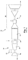
- generator 12 is illustrated as part of a single shaft STAG (steam turbine and gas turbine) combined-cycle system, including generator 12 in axial alignment with a gas turbine 14 and a steam turbine system 16.
- gas turbine 14 includes a compressor 18, a plurality of combustors 20 and a gas turbine section 22 for driving a rotor axially coupled to generator rotor 24.
- Generator rotor 24 at the opposite end of generator 12 is coupled to a series of high, intermediate and low pressure steam turbines 26 which may utilize the high temperature exhaust from the gas turbine and a heat recovery steam generator (not shown) to convert the gas turbine exhaust into useful steam for the bottoming portion of the combined cycle. It will be appreciated that generator rotor 24 is axially aligned with and coupled to the rotors of both gas turbine 14 and steam turbines 26.
- generator 12 includes a body 30 normally supported at a first axial position 112 by opposing feet 32, and at a second axial position 116 by opposing feet 34 (one occluded by body 30) on axially displaced machine foundations 122, 126.
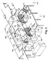
- FIGS. 2 and 3 a perspective view of a system 100 for laterally moving industrial machine 10 ( FIG. 1 ), e.g., generator 12 of a power plant, for maintenance is provided.
- generator 12 is shown separated from turbines 14, 16 ( FIG. 1 ), but the turbines would be located axially adjacent to generator 12, thus preventing removal of generator rotor 24 ( FIG. 1 ).
- system 100 has been installed and generator 12 is in position to be laterally moved; and in FIG. 3 , generator 12 has been laterally moved (illustrated as up on the page) using system 100.
- Generator 12 is shown with rotor generator 24 ( FIG. 1 ) removed, but it would typically still be in place as generator 12 is situated.
- lateral indicates a direction generally perpendicular to a longitudinal axis A of generator 12.
- all mechanical and electrical connections to generator 12 have been removed, including but not limited to foundation anchor bolts; rotor connections to the rotors of turbines 14, 16 ( FIG. 1 ); bus duct; neutral grounding; instrumentation connections; lube oil, seal oil, cooling water, hydrogen and purge piping connections, etc.
- Other industrial machines 10 FIG. 1 ) may have any necessary parts removed to allow for lateral moving in a similar manner.
- System 100 includes a pair of rail elements 104, 106 configured to be positioned laterally below and support generator 12.
- Rail elements 104, 106 allow machine 10 ( FIG. 1 ), e.g., generator 12, to be moved laterally from a first operative position ( FIG. 2 ) to a second, maintenance position ( FIG. 3 ).
- a pair of linear actuators 130, 132 may be configured to laterally move the machine from the first, operative position to the second, maintenance position.
- Rail elements 104, 106 may interact with skids 110, 114 and support rails 120, 124.
- system 100 may include a first skid 110 configured to couple laterally to an underside of generator 12 at first axial position 112, and a second skid 114 configured to couple laterally to an underside of generator 12 at second axial position 116.
- System 100 also includes a first segmented support rail 120 for positioning in sliding, aligned contact with first skid 110 and configured to be supported on a first machine foundation 122; and a second segmented support rail 124 for positioning in sliding, aligned contact with second skid 114 and configured to be positioned on a second machine foundation 126.
- each machine foundation 122, 126 may take a variety of forms, in one embodiment, each machine foundation 122, 126 may include a pair of opposing piers 122A, 122B and 126A, 126B (latter hidden) on opposing sides of generator 12. Similar piers may be employed for different types of machines. As understood, power plant piers are conventionally reinforced concrete slabs engineered to support heavy, vibrating loads. Similar piers may be employed for other types of industrial machines. As understood, during operation of generator 12, feet 32, 34 of generator 12 sit atop piers 122A, 122B, 126A, 126B. As shown in FIG.
- each support rail 120, 124 spans a space or gap 128 between a respective pair of opposing piers 122A, 122B, 126A, 126B in operation.
- each segmented support rail 120, 124 may also extend a distance beyond a periphery of generator 12 on at least one end. That is, rails 120, 124 stick out laterally beyond generator 12.
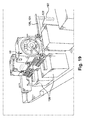
- an optional vertical support column 102 may be provided for supporting a portion of a respective support rail 120, 124 extending beyond a respective machine foundation 122, 126.
- system 100 also includes a pair of linear actuators 130, 132 configured to laterally move generator 12 as each skid 110, 114 slides along a respective segmented support rail 120, 124.
- each segmented support rail 120, 124 may include a number of segments 140 coupled end-to-end to form each rail.
- four segments 140A-D are illustrated. It is understood, however, that any number of segments 140 may be provided in any particular rail 120, 124.
- the number of segments 140 may be determined based on a number of factors such as but not limited to: the overall length required of rails 120, 124 to span gap 128; the available space adjacent generator 12 for staging of system 100; the size of generator 12; the lift capacity of an overhead crane (OHC) used to position rails segments 140; etc.
- OOC overhead crane
- Each segment 140 and thus rails 120, 124 may take the form of any now known or later developed structural element capable of withstanding the loads applied to the rails, such as but not limited to: an H-beam, an I beam, a box beam, etc.
- segments 140 include box beams having access openings 142 ( FIG. 7 ) for accessing end flanges 144.
- End flanges 144 and other parts of segments 140 described herein may be coupled together in any known fashion, e.g., welding, fasteners, etc., capable of withstanding the stresses of operation.
- buttresses 154 may be used where necessary for added strength.
- Segmented support rails 120, 124 are assembled sequentially using segments 140. As illustrated in FIGS. 6 and 8 , segments 140 may be fastened together using removable fasteners such as bolts that extend through mating openings in end flanges 144. In this fashion, rails 120, 124 may be readily assembled, disassembled and moved from location to location. As understood, various other fasteners may be employed, where possible. As shown in FIG. 5 , at least one segment 140A-D of a selected segmented support rail 120, 124 may have a different length than at least one other segment 140A-D of the selected segmented support rail. For example, segment 140A is shown shorter than segment 140B, and segment 140C is shown shorter than all other segments.
- each segment 140A-D may include a plurality of lift rings or eyes 146 for engaging by an OHC hook 148 ( FIG. 7 ), which may be used to lift and position segments.
- Rings or eyes 146 may take a variety of forms, e.g., pivoting hooks, openings in segments 140, etc.
- each segment 140A-D also includes a channel 148 in which a respective skid 110, 114 ( FIGS. 9-10 ) may be guided.
- channel 148 may be formed by upstanding rails 149 on opposing sides of the upper surface of segments 140A-D.
- Upstanding rails 149 may take a variety of forms such as flat plates, or as illustrated best in FIG. 7 , as T-shaped rails set on edge. It is appreciated that channels 148 may also be formed in a variety of other fashions, e.g., machining a groove into a thick upper plate of segments 140, etc. Referring to FIGS.
- each segment 140A-D may include at least one removable skid pad 150 such that each rail 120, 124 includes a plurality of removable skid pads 150 extending along a length thereof.
- Each skid pad 150 may include any now known or later developed material for ensuring smooth movement of skid 110, 114 ( FIGS. 2 and 3 ) therealong.
- skid pad 150 may include a hard plastic such as polytetrafluoroethylene (PTFE).
- PTFE polytetrafluoroethylene
- Each skid pad 150 may be coupled to a respective segment in any fashion such as but not limited to: threaded fasteners (shown), adhesives, tongue-and-groove couplings, etc.
- each segmented support rail 120, 124 may also include a plurality of spaced teeth 152 extending along a length thereof. Teeth 152 are provided for engagement by linear actuators 130, 132 and propulsion thereby, as will be described herein.
- each tooth 152 may extend from a side of upstanding plates 149, and may be formed, for example, from metal plates welded to plates 149.
- upstanding plates 149 include a T-shaped rail positioned on edge
- teeth 152 may extend from an upper edge of the T-shaped rail.
- Buttresses 154 may be employed, where necessary for added strength.
- buttresses 154 are shown below teeth 152, and extending under a base of the T-shaped rail. However, this arrangement is not necessary in all cases as teeth 152 may be arranged in a different location depending on how linear actuators 130, 132 mount to and move along rails 120, 124.
- At least one of the segments, e.g., 140C in FIG. 8 may include a plurality of fastener openings 156 for coupling the at least one segment to a respective machine foundation, e.g., 122A, 122B. Once in position as shown in FIGS. 2 and 3 , selective segments that include fastener openings 156 may be fastened in place on a machine foundation 122, 126 to securely mount segmented rails 120, 124.
- a support rail extender 160 may be provided for temporary coupling to a first segment 140A of a selected segmented support rail 120, 124.
- support rail extender 160 may be used to assist in having each rail 120, 124 span gap 128 between a pair of opposing piers, e.g., 122A, 122B, of one of machine foundations 122, 126 during installation of the selected segmented support rail.
- support rail extender 160 does not actively support generator 12 in operation, it need not be made of the same material as rails 120, 124.
- extender 160 may be made of composite or a light metal such as aluminum.
- skids 110, 114 are configured to mount to an underside of generator 12 and to slidingly support generator 12 on segmented support rails 120, 124.
- FIG. 9 shows a top perspective view of skids 110, 114
- FIG. 10 shows a bottom perspective view of skids 110, 114.
- Each skid 110, 114 includes a beam 170, and a skid member 172 at each end of the beam.
- Beam 170 may be any elongated structural component and may take any of the forms listed herein relative to rails 120, 124.
- Each skid member 172 includes a mount 174 ( FIG.
- Mounts 174 may include, for example, metal plates including fastener openings for, e.g., bolting, to a bottom of generator feet 32, 34.
- Mounts 174 may include, for example, metal plates including fastener openings for, e.g., bolting, to a bottom of generator feet 32, 34.
- a large variety of alternative mechanisms may be employed to mount skids 170 to feet 32, 34, e.g., tongue-and-groove mounts, etc.
- Each skid plate 176 may include any form of skid plate material capable of sliding interaction with skid pads 150 of segmented support rails 120, 124.
- skid members 172 may include metal wear plates made of, for example, stainless steel; however, a large variety of alternatives may be employed such as but not limited to hard plastics such as PTFE. Each skid member 172 may further include an actuator coupling 178 for selective coupling to one of the pair of linear actuators 130, 132 ( FIG. 3 ). Any necessary coupling structure 180 may be provided to properly support and position mount 174 relative to skid member 172 and/or actuator coupling 178, e.g., with backing plates for mount 174 and/or skid member 172, and any necessary buttresses 154 ( FIG. 10 ) for added strength. Skid members 172 may be coupled to beam 170 using any solution, e.g., bolting, welding, etc. Skids 110, 114 may have different structure, coupling points, coupling mechanisms, etc., depending on the type of industrial machine to which they are applied.
- system 100 may also include a lateral support member 184 for coupling opposing feet, e.g., 32A, 32B or 34A, 34B of the industrial machine, e.g., generator (shown in phantom in FIG. 11 ).
- Lateral support member 184 may be provided to add support to feet 32, 34 by preventing bowing of the feet when under lateral movement provided by system 100.
- Lateral support member 184 may include, for example, one or more metal bars or rods that couple to feet 32, 34 in any fashion, e.g., bolting, welding, etc. As also shown in FIG.
- each foot 32, 34 may also include a jacking shelf 186 extending from each axial end thereof for lifting engagement with a climbing jack, as will be described herein.
- Support member(s) 184 may couple to the bodies of feet 32, 34 and/or to jacking shelves 186.
- segmented support rails 120, 124 and skids 110, 114 While rails 120, 124 have been described as including channels 148 into which skid members 172 of skids 110, 114 fits for sliding engagement, it is understood that the channels' position could be switched within the scope of the invention. In this case, skids 110, 114 would include the channel and fit over rails 120, 124.
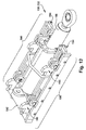
- pair of linear actuators 130, 132 may include a first linear actuator 130 coupled between first segmented support rail 120 and first skid 110, and a second linear actuator 132 coupled between second segmented support rail 124 and second skid 114.
- Each linear actuator may include any now known or later developed linear actuation mechanism 188 capable of applying sufficient force to laterally move industrial machine 10 ( FIG. 1 ), e.g., generator 12, on support rails 120, 124 such as but not limited to a hydraulic cylinder, pneumatic cylinder, etc.
- linear actuators 130, 132 In operation, linear actuators 130, 132 would be positioned in parallel on respective rails 120, 124 and coupled to respective skids 110, 114. Upon activation, linear actuators 130, 132 are synchronized with one another so as to slidingly push industrial machine 10 ( FIG. 1 ), e.g., generator 12, along rails 120, 124 in line with one another, i.e., maintaining the parallel positioning. Any now known or later developed controls may be employed to operate linear actuators 130, 132. In one embodiment, each linear actuator 130, 132 can be activated to stroke to move generator 12 and then be manually re-positioned, after cylinder retraction, relative to each respective rail 120, 124 for re-activation.
- each linear actuator 130, 132 may include a stepper 190 for automatically sequentially moving generator 12 and each linear actuator 130, 132 along rails 120, 124. Details of how stepper 190 functions will be described relative to a method described herein.
- FIGS. 2 and 3 in conjunction with FIGS. 13-18 a method of laterally moving an industrial machine 10 ( FIG. 1 ), such as a generator in a power plant, for maintenance will now be described.
- the method includes steps for installing and using system 100. Although the method is shown applied relative to a generator 12, it may be applied to a variety of other industrial machines as listed herein. Turning to FIGS. 13 and 14 , in preparation for moving of industrial machine 10 ( FIG.
- generator 12 all mechanical and electrical connections to the industrial machine are removed, including but not limited to for generator 12: foundation anchor bolts; rotor connections to the rotors of turbines 14, 16; bus duct; neutral grounding; instrumentation; lube oil, seal oil, cooling water, hydrogen and purge piping connections, etc.
- generator 12 is raised above a pair of machine foundations 122, 126, each machine foundation including a pair of opposing piers 122A, 122B, 126A, 126B ( FIGS. 2-3 ) on opposite lateral sides of the generator. Any bolts or other fasteners mounting generator 12 in place are removed prior to the raising.
- system 100 may also include a plurality of climbing jacks 200 for raising generator 12 in a synchronized manner, maintaining generator 12 horizontally level in both axial and transverse planes as it is moved to a raised position ( FIG. 14 ) above the first and second machine foundations 122, 126.
- generator 12 raising may include using climbing jacks 200 for raising the generator in a synchronized manner to a raised position ( Fig. 14 ) above the first and second machine foundations 122, 126.
- a raised position As will be discussed, installation of first and second skids 110, 114 and first and second segmented support rails 120, 124 may be allowed.
- eight (8) climbing jacks available from Advanced Lifting Equipment of Devon, England or Enerpac of Menomonee Falls, Wisconsin, USA, may be employed.
- Climbing jacks 200 are set under each jacking shelf 186 as shown in the insets of FIGS. 13 and 14 . See also FIG. 11 for locations of jacking shelves 186.
- FIG. 14 For also shown in FIG.
- the method may include coupling opposing feet 32A, 32B and 34A, 34B of generator 12 together with support member(s) 184 prior to the raising.
- Support member(s) 184 may be required for added strength to hold opposing feet together.
- System 100 may also include cribbing 210 for supporting generator 12 during raising thereof to the raised position, and in the raised position. That is, as generator 12 is raised, cribbing 210 can be placed beneath generator 12, e.g., beneath jacking shelves 186, for maintaining the generator in the raised position (or an intermediate position between lowered and raised positions). Once in the raised position and with sufficient cribbing 210 (see FIG. 14 ) in place to support generator 12 in the raised position, climbing jacks 200 may be de-energized.
- first segmented support rail 120 may be installed at first axial position 112 ( FIGS. 2 and 3 ) of generator 12 and supported laterally by the opposing piers 122A, 122B of one of the machine foundations 122, 126.
- second segmented support rail 124 may be installed at second axial position 116 ( FIGS. 2 and 3 ) of generator 12 and supported laterally by opposing piers 126A, 126B ( FIGS. 2 and 3 ) of the other of the machine foundations 126.
- each segmented support rail 120, 124 extends a distance beyond a periphery of the generator on at least one end.
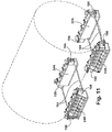
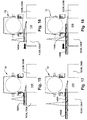
- FIGS. 15-18 show an illustrative embodiment of installing segmented support rails 120, 124.
- generator 12 is in the raised position above piers 122A, 122B, 126A, 126B.
- a first segment 140A of a segmented support rail 120 or 124 is positioned by an overhead crane (OHC) (indicated by triangular lines) coupled by hooks 146 ( FIG. 7 ) on one of the foundation piers 122A, 126A.
- OOC overhead crane
- segments 140 of rails 120, 124 are sequentially installed.
- a preliminary step to segment installation may include temporarily coupling support rail extender 160 to first segment 140A. As shown in FIGS.
- first segment 140A of the rail 122, 124 shown has support rail extender 160 coupled thereto for installation.
- support rail extender 160 assists in having each rail 120, 124 span gap 128 between a pair of opposing piers, e.g., 122A, 122B, of one of machine foundations 122, 126 during installation of the selected segmented support rail.
- FIG. 16 shows initial advancement of first segment 140A under generator 12.
- First segment 140A may be advanced by use of the OHC in a known fashion.
- support rail extender 160 does not span gap 128 at this stage.
- FIG. 17 shows coupling of a second segment 140B to first segment 140A. Segments 140A, 140B may be coupled as described herein, e.g., by bolting flanges 144 ( FIG. 8 ) together.
- the OHC may advance segments 140A, 140B under generator 12.
- support rail extender 160 now allows spanning of gap 128, i.e., extender 160 rests on opposing pier 122B, 126B supporting the portion of the rails already coupled together.
- extender 160 allows grasping by the OHC (from right side of FIG. 18 ) such that segments 140A, 140B may be more readily pulled under generator 12. Additional segments, e.g., segments 140C, 140D ( FIG. 5 ), may then be sequentially added in a similar fashion, until rails 120, 124 are complete and supported on the piers, as shown in FIG. 2 . Although not necessary, once rails 120, 124 are installed, extender 160 may be removed.
- first skid 110 may be coupled laterally to an underside of generator 12 and in alignment with first segmented support rail 120.
- second skid 114 may be coupled laterally to an underside of generator 12 at second axial position 116 and in alignment with second segmented support rail 124.
- the raised position of generator 12 allows skids 110, 114 to be slid under generator 12 in channels 148 ( FIG. 5 ) of rails 120, 124.
- Generator 12 may then be slightly lowered, or skids 110, 114 slightly raised, such that mounts 174 ( FIG. 9 ) may be coupled to respective, axially displaced feet 32, 34 of generator 12, as described herein.
- generator 12 is lowered such that each skid 110, 114 is aligned in contact with a respective support rail 120, 124.
- Generator 12 may be lowered by activation of climbing jacks 200 (see inset FIGS. 13, 14 ) and gradual lowering it with removal of cribbing 210 (see inset FIG. 14 ) until generator 12 is supported by rails 120, 124 and skids 110, 114.
- the jacks and any additional cribbing can be removed. Any necessary leveling of rails 120, 124 and/or skids 110, 114 may be performed as the lowering occurs per conventional rigging practices.
- generator is supported by system 100, i.e., by skids 110, 114 sitting in channels 148 of segmented support rails 120, 124, and the rails being supported on respective opposing piers 122A, 122B and 126A, 126B.
- FIG. 3 shows applying a force to laterally move generator 12 as each skid 110, 114 slides along a respective segmented support rail 120, 124.
- the force applying includes using linear actuators 130, 132 coupled between each segmented support rail 122, 124 and a respective skid 110, 114. More particularly, the force applying may include using first linear actuator 130 coupled between first segmented support rail 122 and first skid 110, and second linear actuator 132 coupled between second segmented support rail 124 and second skid 114. Actuators 130, 132 are synchronized with one another to ensure even movement of each end of generator 12.
- the force applying may include sequentially stepping each linear actuator 130, 132 along a respective segmented support rail.
- Slide pads 150 FIG. 5
- skid plates 176 FIG. 10
- each stepper may engage with plurality of teeth 152 on rails 120, 124 to step the linear actuators in a synchronized manner along the segmented support rail.
- Steppers 190 may be provided on each side of actuation mechanism 188 to ensure actuators correctly align with rails 120, 124.
- a wide variety of steppers 190 may be employed with system 100 ( FIG. 2 ).
- a stepper 190 may include an actuation mechanism mount 192 to mount the stepper to actuation mechanism 188 at one end, and a ratchet system 194 extending along mechanism 192.
- Each ratchet system 194 includes one or more ratchet elements 196, each which engage with a respective tooth 152 ( FIGS. 5 and 6 ) in response to actuation mechanism 188 extending to push generator 12 along rails 120, 124.
- ratchet elements 196 pivot to pass over a respective tooth 152 in response to actuation mechanism 188 retracting.
- ratchets 196 are biased insufficiently to have their position maintained against the frictional force of the weight of generator 12. Consequently, as actuation mechanism 188 retracts, the lateral position of linear actuator 130, 132 relative to a respective rail 122, 124 is advanced.
- ratchets 196 pass over one or more teeth 152 until actuation mechanism 188 is fully retracted. Extension of actuation mechanism 188 again seats at least one ratchet 196 against a respective tooth 152 such that, once again, actuation mechanism 188 pushes generator 12 along support rails 120, 124.
- generator 12 is supported by rails 120, 124 (perhaps with vertical support column 102 ( FIG. 19 ) and a set of piers, e.g., 122A, 126A. In this position, there is nothing blocking access to industrial machine 10 ( FIG. 10 , e.g., generator rotor 24 ( FIG. 1 ), and any repair and/or maintenance can be readily performed. Skids 110, 114 and/or rails 120, 124 may be locked in position per conventional rigging practices so as to not allow movement of industrial machine 10 (e.g., generator 12) during repair and/or maintenance, e.g., removal of generator rotor 24 ( FIG. 1 ).
- the industrial machine can be returned to its original position ( FIG. 2 ) by reversing the order of steps described above. That is, linear actuators 130, 132 can be coupled to rails 120, 124 on the opposite side from that shown in FIG. 3 and generator 12 slidingly forced along rails 120, 124 to the position shown in FIG. 2 . Generator 12 can then be raised such that rails 120, 124 and skids 110, 114 can be removed. Generator 12 is then lowered, remounted to foundations 122, 126 and re-coupled for operation or temporary storage.
- System 100 as described herein provides for laterally moving an industrial machine 10 such as a generator 12 for repair or maintenance.
- System 100 is lower cost compared to conventional gantry systems and can be assembled/disassembled more quickly than gantry systems.
- System 100 is also relatively inexpensive to manufacture compared to conventional permanently mounted movable slabs or heavy duty gantries.
- system 100 is relatively quick to set up due, in part, to the rails being segmented.
- System 100 also may reduce the amount of space necessary for repair and/or maintenance of an industrial machine as only lateral space for the machine adjacent to its normal operation position is necessary. For example, no additional space for cranes, gantries, movable slabs, etc., is necessary.
- many jurisdictions require health and safety certifications of equipment such as system 100. Since system 100 is removable, the certifications can be performed during down time rather than having to be performed in-situ, which reduces set up time and costs.
Landscapes
- Engineering & Computer Science (AREA)
- General Engineering & Computer Science (AREA)
- Mechanical Engineering (AREA)
- Chemical & Material Sciences (AREA)
- Combustion & Propulsion (AREA)
- Manufacture Of Motors, Generators (AREA)
Abstract
Description
- The disclosure relates to a system for moving an industrial machine for maintenance such as a generator from an aligned single shaft gas turbine-generator-steam turbine configuration.
- Large industrial machines such as a gas turbine, generator and steam turbine are often aligned with other structures for operation. For example, the gas turbine, generator and steam turbine may be axially aligned in a single shaft configuration one with the other with the generator located between the gas and steam turbines whereby the turbines drive the generator rotor to produce electric power. This configuration is known as a single shaft STAG (steam and gas) combined-cycle system. In the single shaft STAG combined-cycle system, it will be appreciated that the opposite ends of the generator are mechanically coupled to the gas and steam turbines, respectively. The generators of these systems, similar to other industrial machines, are generally mounted on foundations prepared for supporting these large system generators. Typically, large industrial machines or parts thereof such as the generator rotor, i.e., the generator field, must be removed from the machines for scheduled maintenance or repair. In terms of the generator example, with the three main rotating components of the single shaft combined-cycle system secured to the foundation, and in axial alignment one with the other parts, it is not possible to remove the generator field axially due to the lack of clearance with respect to the turbines at opposite ends of the generator. Maintenance on the gas and steam turbines can typically be performed in situ because the turbine housings are split along a horizontal midline enabling removal of each upper casing, exposing the rotors of the gas and steam turbines. This leaves the lower turbine casings resting on the foundation. However, because the generator is an electromagnetic generator, it is not typically possible to split the generator rotor and casing at the centerline and lift the generator rotor from the generator in a vertical direction. Similar clearance limitations plague maintenance of other industrial machines.
- With regard to generators, prior maintenance has been performed on rotors in single shaft combined-cycle systems, primarily in three ways. Once the generators are mechanically uncoupled from the turbines, the generators are directly lifted (via gantry or crane) from the foundation and moved to a laydown area in the plant where rotor removal in an axial direction is not hindered by the presence of other equipment. Often it is necessary to bring in specialized heavy-duty lifting equipment for these lifts as on-site lift capability is usually inadequate to perform such lifts. Another prior process for maintaining generator rotors requires a movable slab forming part of the foundation for the generator. With the generator located on the movable slab, the generator may be displaced transversely or laterally from between the turbines and thus moved to a position where the turbines do not interfere with axial removal of the generator field. Another prior process mounts the generator on special foundations having removable portions that allow installation of guides that allow rotation of the generator about a vertical axis, thus allowing removal of the generator field. Similar complex configurations are used widely for other forms of large industrial machines.
- A first aspect of the disclosure provides a system for laterally moving an industrial machine for maintenance, the system comprising: a pair of rail elements configured to be positioned laterally below and support the industrial machine, the rail elements allowing the industrial machine to be moved laterally from a first operative position to a second, maintenance position; and a pair of linear actuators configured to laterally move the industrial machine as from the first, operative position to the second, maintenance position.
- A second aspect of the disclosure provides a system for laterally moving an industrial machine of a power plant for maintenance, the system comprising: a first skid configured to couple laterally to an underside of the industrial machine at a first axial position; a second skid configured to couple laterally to an underside of the industrial machine at a second axial position; a first segmented support rail for positioning in sliding, aligned contact with the first skid and configured to be supported on a first machine foundation; a second segmented support rail for positioning in sliding, aligned contact with the second skid and configured to be positioned on a second machine foundation, each segmented support rail extending a distance beyond a periphery of the industrial machine on at least one end; and a pair of linear actuators configured to laterally move the industrial machine as each skid slides along a respective segmented support rail.
- A further embodiment may include a support rail extender for temporary coupling to a first segment of a selected segmented support rail for spanning a gap between a pair of opposing piers of one of the machine foundations during installation of the selected segmented support rail.
- A further embodiment may include each segment of the segmented support rails including at least one removable skid plate.
- A further embodiment may provide at least one segment of a selected segmented support rail having a different length than at least one other segment of the selected segmented support rail.
- An additional embodiment may include each skid including: a beam; and a skid member at each end of the beam, each skid member including a mount for coupling the skid member to a foot of the industrial machine and an opposing, skid plate for sliding engagement with a respective segmented support rail.
- A further embodiment may include each skid member further including an actuator coupling for selective coupling to one of the pair of linear actuators.
- Another further embodiment may provide the pair of linear actuators including a first linear actuator coupled between the first segmented support rail and the first skid, and a second linear actuator coupled between the second segmented support rail and the second skid, and wherein the first and second linear actuator are synchronized with one another.
- A further embodiment may include each segmented support rail including a plurality of spaced teeth extending along a length thereof, and each linear actuator including a linear actuating mechanism and a stepper sequentially engaging with the plurality of teeth to step the linear actuator along the segmented support rail.
- A further embodiment may provide a plurality of climbing jacks for raising the industrial machine in a synchronized manner to a raised position above the first and second machine foundations, allowing installation of the first and second skids and the first and second segmented support rails.
- An additional embodiment may include cribbing for supporting the industrial machine during raising thereof to the raised position.
- Another further embodiment may include each machine foundation including a pair of opposing piers on opposing sides of the industrial machine, each support rail spanning a space between a respective pair of opposing piers in operation.
- A further embodiment may provide a support member for coupling opposing feet of the industrial machine together.
- Another embodiment may include a support rail for supporting a portion of a respective support rail extending beyond a respective machine foundation.
- Another embodiment may include one of the skids and the segmented support rails including a channel into which the other one of the skid and the segmented support rail is engaged.
- Another embodiment may include each segment of the segmented support rails including a plurality of lift rings or eyes.
- Another embodiment may provide at least one of the segments of each segmented support rail including a plurality of fastener openings for coupling the at least one segment to a respective machine foundation.
- A third aspect may include a system for laterally moving an industrial machine for maintenance, the system comprising: a pair of segmented rail elements configured to be positioned laterally below and support the industrial machine, the segmented rail elements allowing the industrial machine to be moved laterally from a first operative position to a second, maintenance position, wherein the pair of segmented rail elements includes: a first skid configured to couple laterally to an underside of the industrial machine at a first axial position; a second skid configured to couple laterally to an underside of the industrial machine at a second axial position; a first segmented support rail for positioning in sliding, aligned contact with the first skid and configured to be supported on a first machine foundation; a second segmented support rail for positioning in sliding, aligned contact with the second skid and configured to be positioned on a second machine foundation, each segmented support rail extending a distance beyond a periphery of the industrial machine on at least one end; and a pair of linear actuators configured to laterally move the industrial machine from the first, operative position to the second, maintenance position, and wherein at least one segment of a selected segmented support rail has a different length than at least one other segment of the selected segmented support rail.
- A fourth aspect of the disclosure provides a method of laterally moving an industrial machine for maintenance, the method comprising: supporting the industrial machine on a pair of rail elements configured to be positioned laterally below and support the industrial machine, the rail elements allowing the industrial machine to be moved laterally from a first operative position to a second, maintenance position; and moving the industrial machine laterally using a pair of linear actuators configured to laterally move the industrial machine from the first, operative position to the second, maintenance position.
- A fifth aspect of the disclosure provides a method of laterally moving an industrial machine for maintenance, the method comprising: raising the industrial machine above a pair of machine foundations, each machine foundation including a pair of opposing piers on opposite lateral sides of the industrial machine; installing a first segmented support rail at a first axial position of the industrial machine and supported laterally by the opposing piers of one of the machine foundations; installing a second segmented support rail at a second axial position of the industrial machine and supported laterally by opposing piers of the other of the machine foundations, each segmented support rail extending a distance beyond a periphery of the industrial machine on at least one end; coupling a first skid laterally to an underside of the industrial machine and in alignment with the first segmented support rail; coupling a second skid laterally to an underside of the industrial machine at a second axial position and in alignment with the second segmented support rail; lowering the industrial machine such that each skid is aligned in contact with a respective support rail; and applying a force to laterally move the industrial machine as each skid slides along a respective segmented support rail.
- In one embodiment, the supporting may include: raising the industrial machine above a pair of machine foundations, each machine foundation including a pair of opposing piers on opposite lateral sides of the industrial machine; installing a first segmented support rail at a first axial position of the industrial machine and supported laterally by the opposing piers of one of the machine foundations; installing a second segmented support rail at a second axial position of the industrial machine and supported laterally by opposing piers of the other of the machine foundations, each segmented support rail extending a distance beyond a periphery of the industrial machine on at least one end; coupling a first skid laterally to an underside of the industrial machine and in alignment with the first segmented support rail; coupling a second skid laterally to an underside of the industrial machine at a second axial position and in alignment with the second segmented support rail; lowering the industrial machine such that each skid is aligned in contact with a respective support rail; and wherein the moving includes applying a force to laterally move the industrial machine as each skid slides along a respective segmented support rail.
- In another embodiment, each skid coupling may include coupling the skid to a respective, axially displaced foot of the industrial machine.
- In yet another embodiment, each segmented support rail installing may include installing the segmented support rail in sequential segments.
- Another embodiment may include temporarily coupling a support rail extender to a first segment of a selected segmented support rail for spanning a gap between a pair of opposing piers of one of the machine foundations during the installing of the selected segmented support rail.
- In another embodiment, the pair of linear actuators may include a first linear actuator coupled between the first segmented support rail and the first skid, and a second linear actuator coupled between the second segmented support rail and the second skid, and wherein the first and second linear actuator are synchronized with one another. Further, the force applying may include sequentially stepping each linear actuator along a respective segmented support rail.
- In another embodiment, the industrial machine raising may include using a plurality of climbing jacks for raising the industrial machine in a synchronized manner to a raised position above the first and second machine foundations.
- Another embodiment may include placing cribbing beneath the industrial machine for maintaining the industrial machine in the raised position.
- Yet another embodiment may include coupling opposing feet of the industrial machine together with a support member prior to the raising.
- A sixth aspect of the invention may provide a method of laterally moving an industrial machine for maintenance, the method comprising: raising the industrial machine above a pair of machine foundations, each machine foundation including a pair of opposing piers on opposite lateral sides of the industrial machine; installing a first segmented support rail at a first axial position of the industrial machine and supported laterally by the opposing piers of one of the machine foundations; installing a second segmented support rail at a second axial position of the industrial machine and supported laterally by opposing piers of the other of the machine foundations, each segmented support rail extending a distance beyond a periphery of the industrial machine on at least one end; coupling a first skid laterally to an underside of the industrial machine and in alignment with the first segmented support rail; coupling a second skid laterally to an underside of the industrial machine at a second axial position and in alignment with the second segmented support rail; lowering the industrial machine such that each skid is aligned in contact with a respective support rail; and moving the industrial machine laterally using a pair of linear actuators, each linear actuator coupled to a respective skid and configured to laterally move the industrial machine from a first, operative position to a second, maintenance position as each skid slides along a respective segmented support rail.
- The illustrative aspects or embodiments of the present disclosure are arranged to solve the problems herein described and/or other problems not discussed.
- These and other features of this disclosure will be more readily understood from the following detailed description of the various aspects of the disclosure taken in conjunction with the accompanying drawings that depict various embodiments of the disclosure, in which:
-
FIG. 1 shows a schematic view of a conventional single shaft STAG combined-cycle system. -
FIG. 2 shows a perspective view of a system for laterally moving an industrial machine such as a generator prior to the lateral moving according to embodiments of the invention. -
FIG. 3 shows a perspective view of the system ofFIG. 2 after the lateral moving. -
FIG. 4 shows a detailed perspective view of a linear actuator of the system for laterally moving an industrial machine according to embodiments of the invention. -
FIG. 5 shows a perspective view of a segmented support rail of the system according to embodiments of the invention. -
FIG. 6 shows an enlarged perspective view of a detail of a segmented support rail ofFIG. 5 . -
FIG. 7 shows a perspective view of a segment of the segmented support rail of the system according to embodiments of the invention. -
FIG. 8 shows a perspective view of a coupling of two segments of the segmented support rail of the system according to embodiments of the invention. -
FIG. 9 shows a top perspective view of a skid of the system for laterally moving an industrial machine according to embodiments of the invention. -
FIG. 10 shows a bottom perspective view of the skid ofFIG. 9 . -
FIG. 11 shows a perspective view of a set of feet for the industrial machine including lateral support members of the system according to embodiments of the invention. -
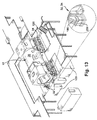
FIG. 12 shows a perspective view of a linear actuator of the system according to embodiments of the invention. -
FIGS. 13 and14 show perspective views of a step of raising the industrial machine using the system according to embodiments of the invention. -
FIGS. 15-18 show end views of the steps of installing a segmented support rail of the system according to embodiments of the invention. -
FIG. 19 shows a perspective view of the system including a vertical support column for one of the segmented support rails. - It is noted that the drawings of the disclosure are not to scale. The drawings are intended to depict only typical aspects of the disclosure, and therefore should not be considered as limiting the scope of the disclosure. In the drawings, like numbering represents like elements between the drawings.
- As indicated above, the disclosure provides a system and method for laterally moving an industrial machine, such as a generator in a power plant, for maintenance.
- Referring now to the drawings, particularly to
FIG. 1 , anindustrial machine 10 in one example may include agenerator 12. In the example shown,generator 12 is illustrated as part of a single shaft STAG (steam turbine and gas turbine) combined-cycle system, includinggenerator 12 in axial alignment with agas turbine 14 and asteam turbine system 16. As illustrated,gas turbine 14 includes acompressor 18, a plurality ofcombustors 20 and agas turbine section 22 for driving a rotor axially coupled togenerator rotor 24.Generator rotor 24 at the opposite end ofgenerator 12 is coupled to a series of high, intermediate and lowpressure steam turbines 26 which may utilize the high temperature exhaust from the gas turbine and a heat recovery steam generator (not shown) to convert the gas turbine exhaust into useful steam for the bottoming portion of the combined cycle. It will be appreciated thatgenerator rotor 24 is axially aligned with and coupled to the rotors of bothgas turbine 14 andsteam turbines 26. Referring toFIGS. 2 and3 ,generator 12 includes abody 30 normally supported at a firstaxial position 112 by opposingfeet 32, and at a secondaxial position 116 by opposing feet 34 (one occluded by body 30) on axially displacedmachine foundations generator 12, it is emphasize that the teachings of the invention are equally applicable to a wide variety ofindustrial machines 10 including but not limited to: gas turbines, steam turbines, compressors, jet engines, water-powered turbines, etc. - With continuing reference to
FIGS. 2 and3 , a perspective view of asystem 100 for laterally moving industrial machine 10 (FIG. 1 ), e.g.,generator 12 of a power plant, for maintenance is provided. InFIGS. 2 and3 ,generator 12 is shown separated fromturbines 14, 16 (FIG. 1 ), but the turbines would be located axially adjacent togenerator 12, thus preventing removal of generator rotor 24 (FIG. 1 ). InFIG. 2 ,system 100 has been installed andgenerator 12 is in position to be laterally moved; and inFIG. 3 ,generator 12 has been laterally moved (illustrated as up on the page) usingsystem 100.Generator 12 is shown with rotor generator 24 (FIG. 1 ) removed, but it would typically still be in place asgenerator 12 is situated. As used herein, "lateral" indicates a direction generally perpendicular to a longitudinal axis A ofgenerator 12. In preparation for moving, all mechanical and electrical connections togenerator 12 have been removed, including but not limited to foundation anchor bolts; rotor connections to the rotors ofturbines 14, 16 (FIG. 1 ); bus duct; neutral grounding; instrumentation connections; lube oil, seal oil, cooling water, hydrogen and purge piping connections, etc. Other industrial machines 10 (FIG. 1 ) may have any necessary parts removed to allow for lateral moving in a similar manner. -
System 100 includes a pair ofrail elements support generator 12.Rail elements FIG. 1 ), e.g.,generator 12, to be moved laterally from a first operative position (FIG. 2 ) to a second, maintenance position (FIG. 3 ). A pair oflinear actuators Rail elements skids support rails system 100 may include afirst skid 110 configured to couple laterally to an underside ofgenerator 12 at firstaxial position 112, and asecond skid 114 configured to couple laterally to an underside ofgenerator 12 at secondaxial position 116.System 100 also includes a firstsegmented support rail 120 for positioning in sliding, aligned contact withfirst skid 110 and configured to be supported on afirst machine foundation 122; and a secondsegmented support rail 124 for positioning in sliding, aligned contact withsecond skid 114 and configured to be positioned on asecond machine foundation 126. Althoughmachine foundation machine foundation piers generator 12. Similar piers may be employed for different types of machines. As understood, power plant piers are conventionally reinforced concrete slabs engineered to support heavy, vibrating loads. Similar piers may be employed for other types of industrial machines. As understood, during operation ofgenerator 12,feet generator 12 sit atoppiers FIG. 3 and as will be described herein, eachsupport rail gap 128 between a respective pair of opposingpiers FIG. 2 , eachsegmented support rail generator 12 on at least one end. That is, rails 120, 124 stick out laterally beyondgenerator 12. Where necessary, as shown inFIG. 19 , an optionalvertical support column 102 may be provided for supporting a portion of arespective support rail respective machine foundation FIGS. 2 and3 , and in an enlarged perspective view inFIG. 4 ,system 100 also includes a pair oflinear actuators generator 12 as eachskid segmented support rail - Referring to
FIGS. 5-8 , details of segmented support rails 120, 124 are illustrated. As shown inFIG. 5 , eachsegmented support rail FIG. 5 , foursegments 140A-D are illustrated. It is understood, however, that any number of segments 140 may be provided in anyparticular rail rails span gap 128; the available spaceadjacent generator 12 for staging ofsystem 100; the size ofgenerator 12; the lift capacity of an overhead crane (OHC) used to position rails segments 140; etc. Each segment 140 and thus rails 120, 124 may take the form of any now known or later developed structural element capable of withstanding the loads applied to the rails, such as but not limited to: an H-beam, an I beam, a box beam, etc. In the example shown, segments 140 include box beams having access openings 142 (FIG. 7 ) for accessingend flanges 144.End flanges 144 and other parts of segments 140 described herein may be coupled together in any known fashion, e.g., welding, fasteners, etc., capable of withstanding the stresses of operation. As shown for example inFIG. 8 , buttresses 154 may be used where necessary for added strength. - Segmented support rails 120, 124 are assembled sequentially using segments 140. As illustrated in
FIGS. 6 and8 , segments 140 may be fastened together using removable fasteners such as bolts that extend through mating openings inend flanges 144. In this fashion, rails 120, 124 may be readily assembled, disassembled and moved from location to location. As understood, various other fasteners may be employed, where possible. As shown inFIG. 5 , at least onesegment 140A-D of a selectedsegmented support rail other segment 140A-D of the selected segmented support rail. For example,segment 140A is shown shorter thansegment 140B, andsegment 140C is shown shorter than all other segments.Different length segments 140A-D allow for assembly ofrails space 128 between foundation piers, e.g., 122A, 122B. As shown best inFIGS. 6 and7 , eachsegment 140A-D may include a plurality of lift rings oreyes 146 for engaging by an OHC hook 148 (FIG. 7 ), which may be used to lift and position segments. Rings oreyes 146 may take a variety of forms, e.g., pivoting hooks, openings in segments 140, etc. - Referring to
FIGS. 5-7 , eachsegment 140A-D also includes achannel 148 in which arespective skid 110, 114 (FIGS. 9-10 ) may be guided. In one embodiment,channel 148 may be formed byupstanding rails 149 on opposing sides of the upper surface ofsegments 140A-D.Upstanding rails 149 may take a variety of forms such as flat plates, or as illustrated best inFIG. 7 , as T-shaped rails set on edge. It is appreciated thatchannels 148 may also be formed in a variety of other fashions, e.g., machining a groove into a thick upper plate of segments 140, etc. Referring toFIGS. 5 and 6 , eachsegment 140A-D may include at least oneremovable skid pad 150 such that eachrail removable skid pads 150 extending along a length thereof. Eachskid pad 150 may include any now known or later developed material for ensuring smooth movement ofskid 110, 114 (FIGS. 2 and3 ) therealong. In one example,skid pad 150 may include a hard plastic such as polytetrafluoroethylene (PTFE). Eachskid pad 150 may be coupled to a respective segment in any fashion such as but not limited to: threaded fasteners (shown), adhesives, tongue-and-groove couplings, etc. - Referring to
FIGS. 6 ,7 and8 , eachsegmented support rail teeth 152 extending along a length thereof.Teeth 152 are provided for engagement bylinear actuators tooth 152 may extend from a side ofupstanding plates 149, and may be formed, for example, from metal plates welded toplates 149. For example, in one embodiment shown inFIG. 8 , whereupstanding plates 149 include a T-shaped rail positioned on edge,teeth 152 may extend from an upper edge of the T-shaped rail.Buttresses 154 may be employed, where necessary for added strength. InFIG. 8 , buttresses 154 are shown belowteeth 152, and extending under a base of the T-shaped rail. However, this arrangement is not necessary in all cases asteeth 152 may be arranged in a different location depending on howlinear actuators rails FIG. 8 , may include a plurality offastener openings 156 for coupling the at least one segment to a respective machine foundation, e.g., 122A, 122B. Once in position as shown inFIGS. 2 and3 , selective segments that includefastener openings 156 may be fastened in place on amachine foundation rails - Referring to
FIGS. 2 ,3 and5 , asupport rail extender 160 may be provided for temporary coupling to afirst segment 140A of a selectedsegmented support rail support rail extender 160 may be used to assist in having eachrail span gap 128 between a pair of opposing piers, e.g., 122A, 122B, of one ofmachine foundations support rail extender 160 does not actively supportgenerator 12 in operation, it need not be made of the same material asrails extender 160 may be made of composite or a light metal such as aluminum. - Referring to
FIGS. 9 and10 , details ofskids Skids generator 12 and to slidinglysupport generator 12 on segmented support rails 120, 124.FIG. 9 shows a top perspective view ofskids FIG. 10 shows a bottom perspective view ofskids skid beam 170, and askid member 172 at each end of the beam.Beam 170 may be any elongated structural component and may take any of the forms listed herein relative torails skid member 172 includes a mount 174 (FIG. 9 ) for coupling the skid member to afoot generator 12 and an opposing, skid plate 176 (FIG. 10 ) for sliding engagement with a respectivesegmented support rail channel 148.Mounts 174 may include, for example, metal plates including fastener openings for, e.g., bolting, to a bottom ofgenerator feet skids 170 tofeet skid plate 176 may include any form of skid plate material capable of sliding interaction withskid pads 150 of segmented support rails 120, 124. In one embodiment,skid members 172 may include metal wear plates made of, for example, stainless steel; however, a large variety of alternatives may be employed such as but not limited to hard plastics such as PTFE. Eachskid member 172 may further include anactuator coupling 178 for selective coupling to one of the pair oflinear actuators 130, 132 (FIG. 3 ). Anynecessary coupling structure 180 may be provided to properly support and position mount 174 relative to skidmember 172 and/oractuator coupling 178, e.g., with backing plates formount 174 and/orskid member 172, and any necessary buttresses 154 (FIG. 10 ) for added strength.Skid members 172 may be coupled tobeam 170 using any solution, e.g., bolting, welding, etc.Skids - Although not part of
skids FIG. 11 ,system 100 may also include alateral support member 184 for coupling opposing feet, e.g., 32A, 32B or 34A, 34B of the industrial machine, e.g., generator (shown in phantom inFIG. 11 ).Lateral support member 184 may be provided to add support tofeet system 100.Lateral support member 184 may include, for example, one or more metal bars or rods that couple tofeet FIG. 11 , eachfoot shelf 186 extending from each axial end thereof for lifting engagement with a climbing jack, as will be described herein. Support member(s) 184 may couple to the bodies offeet shelves 186. - With further regard to segmented support rails 120, 124 and
skids rails channels 148 into whichskid members 172 ofskids rails - Turning to
FIG. 12 , a perspective view of one embodiment of alinear actuator FIGS. 2 and3 , pair oflinear actuators linear actuator 130 coupled between firstsegmented support rail 120 andfirst skid 110, and a secondlinear actuator 132 coupled between secondsegmented support rail 124 andsecond skid 114. Each linear actuator may include any now known or later developedlinear actuation mechanism 188 capable of applying sufficient force to laterally move industrial machine 10 (FIG. 1 ), e.g.,generator 12, onsupport rails linear actuators respective rails respective skids linear actuators FIG. 1 ), e.g.,generator 12, alongrails linear actuators linear actuator generator 12 and then be manually re-positioned, after cylinder retraction, relative to eachrespective rail generator 12, eachlinear actuator stepper 190 for automatically sequentially movinggenerator 12 and eachlinear actuator rails stepper 190 functions will be described relative to a method described herein. - Returning to
FIGS. 2 and3 in conjunction withFIGS. 13-18 , a method of laterally moving an industrial machine 10 (FIG. 1 ), such as a generator in a power plant, for maintenance will now be described. The method includes steps for installing and usingsystem 100. Although the method is shown applied relative to agenerator 12, it may be applied to a variety of other industrial machines as listed herein. Turning toFIGS. 13 and14 , in preparation for moving of industrial machine 10 (FIG. 1 ), e.g.,generator 12, all mechanical and electrical connections to the industrial machine are removed, including but not limited to for generator 12: foundation anchor bolts; rotor connections to the rotors ofturbines - In a first step, shown in
FIGS. 13 and14 ,generator 12 is raised above a pair ofmachine foundations piers FIGS. 2-3 ) on opposite lateral sides of the generator. Any bolts or otherfasteners mounting generator 12 in place are removed prior to the raising. As shown inFIG. 13 ,system 100 may also include a plurality of climbingjacks 200 for raisinggenerator 12 in a synchronized manner, maintaininggenerator 12 horizontally level in both axial and transverse planes as it is moved to a raised position (FIG. 14 ) above the first andsecond machine foundations generator 12 raising may include usingclimbing jacks 200 for raising the generator in a synchronized manner to a raised position (Fig. 14 ) above the first andsecond machine foundations second skids shelf 186 as shown in the insets ofFIGS. 13 and14 . See alsoFIG. 11 for locations of jackingshelves 186. As also shown inFIG. 11 , where necessary, the method may includecoupling opposing feet generator 12 together with support member(s) 184 prior to the raising. Support member(s) 184 may be required for added strength to hold opposing feet together.System 100 may also include cribbing 210 for supportinggenerator 12 during raising thereof to the raised position, and in the raised position. That is, asgenerator 12 is raised, cribbing 210 can be placed beneathgenerator 12, e.g., beneath jackingshelves 186, for maintaining the generator in the raised position (or an intermediate position between lowered and raised positions). Once in the raised position and with sufficient cribbing 210 (seeFIG. 14 ) in place to supportgenerator 12 in the raised position, climbingjacks 200 may be de-energized. - Turning to
FIGS. 2 and3 in conjunction withFIGS. 15-18 , in a next step, firstsegmented support rail 120 may be installed at first axial position 112 (FIGS. 2 and3 ) ofgenerator 12 and supported laterally by the opposingpiers machine foundations segmented support rail 124 may be installed at second axial position 116 (FIGS. 2 and3 ) ofgenerator 12 and supported laterally by opposingpiers FIGS. 2 and3 ) of the other of themachine foundations 126. As noted above, in a final position, eachsegmented support rail -
FIGS. 15-18 show an illustrative embodiment of installing segmented support rails 120, 124. InFIGS. 15-18 ,generator 12 is in the raised position abovepiers FIG. 15 , afirst segment 140A of asegmented support rail FIG. 7 ) on one of thefoundation piers rails support rail extender 160 tofirst segment 140A. As shown inFIGS. 15-18 ,first segment 140A of therail support rail extender 160 coupled thereto for installation. As noted,support rail extender 160 assists in having eachrail span gap 128 between a pair of opposing piers, e.g., 122A, 122B, of one ofmachine foundations -
FIG. 16 shows initial advancement offirst segment 140A undergenerator 12.First segment 140A may be advanced by use of the OHC in a known fashion. As shown,support rail extender 160 does not spangap 128 at this stage.FIG. 17 shows coupling of asecond segment 140B tofirst segment 140A.Segments FIG. 8 ) together. Once coupled, as shown inFIG. 18 , the OHC may advancesegments generator 12. As shown,support rail extender 160 now allows spanning ofgap 128, i.e.,extender 160 rests on opposingpier extender 160 allows grasping by the OHC (from right side ofFIG. 18 ) such thatsegments generator 12. Additional segments, e.g.,segments FIG. 5 ), may then be sequentially added in a similar fashion, untilrails FIG. 2 . Although not necessary, once rails 120, 124 are installed,extender 160 may be removed. - As shown in
FIG. 2 ,first skid 110 may be coupled laterally to an underside ofgenerator 12 and in alignment with firstsegmented support rail 120. In a similar fashion,second skid 114 may be coupled laterally to an underside ofgenerator 12 at secondaxial position 116 and in alignment with secondsegmented support rail 124. Here, the raised position ofgenerator 12 allowsskids generator 12 in channels 148 (FIG. 5 ) ofrails Generator 12 may then be slightly lowered, or skids 110, 114 slightly raised, such that mounts 174 (FIG. 9 ) may be coupled to respective, axially displacedfeet generator 12, as described herein. - Next, as shown in
FIG. 2 ,generator 12 is lowered such that eachskid respective support rail Generator 12 may be lowered by activation of climbing jacks 200 (see insetFIGS. 13, 14 ) and gradual lowering it with removal of cribbing 210 (see insetFIG. 14 ) untilgenerator 12 is supported byrails skids rails skids system 100, i.e., byskids channels 148 of segmented support rails 120, 124, and the rails being supported on respective opposingpiers -
FIG. 3 shows applying a force to laterally movegenerator 12 as eachskid segmented support rail linear actuators segmented support rail respective skid linear actuator 130 coupled between firstsegmented support rail 122 andfirst skid 110, and secondlinear actuator 132 coupled between secondsegmented support rail 124 andsecond skid 114.Actuators generator 12. - As will be described, the force applying may include sequentially stepping each
linear actuator FIG. 5 ) and skid plates 176 (FIG. 10 ) allow sliding motion ofskids generator 12 to which they are mounted as part ofskids FIG. 3 . - Referring again to
FIG. 12 , wherelinear actuators steppers 190, each stepper may engage with plurality ofteeth 152 onrails Steppers 190 may be provided on each side ofactuation mechanism 188 to ensure actuators correctly align withrails steppers 190 may be employed with system 100 (FIG. 2 ). In the example shown, astepper 190 may include anactuation mechanism mount 192 to mount the stepper toactuation mechanism 188 at one end, and aratchet system 194 extending alongmechanism 192. Eachratchet system 194 includes one ormore ratchet elements 196, each which engage with a respective tooth 152 (FIGS. 5 and 6 ) in response toactuation mechanism 188 extending to pushgenerator 12 alongrails elements 196 pivot to pass over arespective tooth 152 in response toactuation mechanism 188 retracting. In this latter movement, ratchets 196 are biased insufficiently to have their position maintained against the frictional force of the weight ofgenerator 12. Consequently, asactuation mechanism 188 retracts, the lateral position oflinear actuator respective rail linear actuators more teeth 152 untilactuation mechanism 188 is fully retracted. Extension ofactuation mechanism 188 again seats at least oneratchet 196 against arespective tooth 152 such that, once again,actuation mechanism 188 pushesgenerator 12 along support rails 120, 124. - Once
generator 12 is in the position shown inFIG. 3 ,generator 12 is supported byrails 120, 124 (perhaps with vertical support column 102 (FIG. 19 ) and a set of piers, e.g., 122A, 126A. In this position, there is nothing blocking access to industrial machine 10 (FIG. 10 , e.g., generator rotor 24 (FIG. 1 ), and any repair and/or maintenance can be readily performed.Skids rails FIG. 1 ). Once repair and/or maintenance is performed, or if generator rotor 24 (FIG. 1 ) is to be removed for a sustained period of time, the industrial machine (generator 12) can be returned to its original position (FIG. 2 ) by reversing the order of steps described above. That is,linear actuators rails FIG. 3 andgenerator 12 slidingly forced alongrails FIG. 2 .Generator 12 can then be raised such thatrails skids Generator 12 is then lowered, remounted tofoundations - The foregoing description and drawings show some of the processing associated according to several embodiments of this disclosure. In this regard, the progression of drawings and their related description represent steps associated with embodiments of the method described. It should also be noted that in some alternative implementations, the acts noted in the drawings or description may occur out of the order noted in the figure or, for example, may in fact be executed substantially concurrently or in the reverse order, depending upon the act involved. For example, in an alternative embodiment, skids 110, 114 may be mounted to
feet generator 12 prior to installation of support rails 120, 124. -
System 100 as described herein provides for laterally moving anindustrial machine 10 such as agenerator 12 for repair or maintenance.System 100 is lower cost compared to conventional gantry systems and can be assembled/disassembled more quickly than gantry systems.System 100 is also relatively inexpensive to manufacture compared to conventional permanently mounted movable slabs or heavy duty gantries. In addition,system 100 is relatively quick to set up due, in part, to the rails being segmented.System 100 also may reduce the amount of space necessary for repair and/or maintenance of an industrial machine as only lateral space for the machine adjacent to its normal operation position is necessary. For example, no additional space for cranes, gantries, movable slabs, etc., is necessary. Furthermore, many jurisdictions require health and safety certifications of equipment such assystem 100. Sincesystem 100 is removable, the certifications can be performed during down time rather than having to be performed in-situ, which reduces set up time and costs. - The terminology used herein is for the purpose of describing particular embodiments only and is not intended to be limiting of the disclosure. As used herein, the singular forms "a", "an" and "the" are intended to include the plural forms as well, unless the context clearly indicates otherwise. It will be further understood that the terms "comprises" and/or "comprising," when used in this specification, specify the presence of stated features, integers, steps, operations, elements, and/or generators, but do not preclude the presence or addition of one or more other features, integers, steps, operations, elements, generators, and/or groups thereof.
- The corresponding structures, materials, acts, and equivalents of all means or step plus function elements in the claims below are intended to include any structure, material, or act for performing the function in combination with other claimed elements as specifically claimed. The description of the present disclosure has been presented for purposes of illustration and description, but is not intended to be exhaustive or limited to the disclosure in the form disclosed. Many modifications and variations will be apparent to those of ordinary skill in the art without departing from the scope and spirit of the disclosure. The embodiment was chosen and described in order to best explain the principles of the disclosure and the practical application, and to enable others of ordinary skill in the art to understand the disclosure for various embodiments with various modifications as are suited to the particular use contemplated.
Claims (10)
- A method of laterally moving an industrial machine (10) for maintenance, the method comprising:supporting the industrial machine (10) on a pair of rail elements (104, 106) configured to be positioned laterally below and support the industrial machine (10), the rail elements (104, 106) allowing the industrial machine (10) to be moved laterally from a first operative position to a second, maintenance position; andmoving the industrial machine (10) laterally using a pair of linear actuators (130, 132), each linear actuator (130, 132) coupled to a respective rail (120) element and configured to laterally move the industrial machine (10) from the first, operative position to the second, maintenance position.
- The method of claim 1, wherein the supporting includes:raising the industrial machine (10) above a pair of machine (10) foundations, each machine (10) foundation including a pair of opposing piers (122A, 122B, 126A, 126B) on opposite lateral sides of the industrial machine (10);installing a first segmented support rail (120) at a first axial position (112) of the industrial machine (10) and supported laterally by the opposing piers (122A, 122B, 126A, 126B) of one of the machine (10) foundations;installing a second segmented support rail (120) at a second axial position (116) of the industrial machine (10) and supported laterally by opposing piers (122A, 122B, 126A, 126B) of the other of the machine (10) foundations, each segmented support rail (120) extending a distance beyond a periphery of the industrial machine (10) on at least one end;coupling a first skid (110) laterally to an underside of the industrial machine (10) and in alignment with the first segmented support rail (120);coupling a second skid (114) laterally to an underside of the industrial machine (10) at a second axial position (116) and in alignment with the second segmented support rail (120);lowering the industrial machine (10) such that each skid (110) is aligned in contact with a respective support rail (120); andwherein the moving includes applying a force using the pair of linear actuators (130, 132) to laterally move the industrial machine (10) as each skid (110) slides along a respective segmented support rail (120).
- The method of claim 2, wherein each skid (110) coupling includes coupling the skid (110) to a respective, axially displaced foot (32, 34) of the industrial machine (10).
- The method of claim 2, wherein each segmented support rail (120) installing includes installing the segmented support rail (120) in sequential segments (140).
- The method of claim 2, further comprising temporarily coupling a support rail (120) extender (160) to a first segment (140A) of a selected segmented support rail (120) for spanning a gap (128) between a pair of opposing piers (122A, 122B, 126A, 126B) of one of the machine (10) foundations during the installing of the selected segmented support rail (120).
- The method of claim 2, wherein the pair of linear actuators (130, 132) includes a first linear actuator (130, 132) coupled between the first segmented support rail (120) and the first skid (110), and a second linear actuator (130, 132) coupled between the second segmented support rail (120) and the second skid (114), and wherein the first and second linear actuator (130, 132) are synchronized with one another.
- The method of claim 6, wherein the force applying includes sequentially stepping each linear actuator (130, 132) along a respective segmented support rail (120).
- The method of claim 2, wherein the industrial machine (10) raising includes using a plurality of climbing jacks (200) for raising the industrial machine (10) in a synchronized manner to a raised position above the first and second machine (10) foundations.
- The method of claim 8, further comprising placing cribbing beneath the industrial machine (10) for maintaining the industrial machine (10) in the raised position.
- The method of claim 2, further comprising coupling opposing feet (32, 34) of the industrial machine (10) together with a support member prior to the raising.
Applications Claiming Priority (1)
| Application Number | Priority Date | Filing Date | Title |
|---|---|---|---|
| US14/737,524 US10054253B2 (en) | 2014-12-05 | 2015-06-12 | System for laterally moving industrial machine |
Publications (2)
| Publication Number | Publication Date |
|---|---|
| EP3103973A1 true EP3103973A1 (en) | 2016-12-14 |
| EP3103973B1 EP3103973B1 (en) | 2019-03-27 |
Family
ID=56615811
Family Applications (1)
| Application Number | Title | Priority Date | Filing Date |
|---|---|---|---|
| EP16173957.8A Active EP3103973B1 (en) | 2015-06-12 | 2016-06-10 | System for laterally moving industrial machine |
Country Status (1)
| Country | Link |
|---|---|
| EP (1) | EP3103973B1 (en) |
Cited By (2)
| Publication number | Priority date | Publication date | Assignee | Title |
|---|---|---|---|---|
| CN109015542A (en) * | 2018-08-13 | 2018-12-18 | 安徽天裕汽车零部件制造有限公司 | A kind of hydraulic controller of vehicle chassis components rotation machine table |
| WO2020162940A1 (en) * | 2019-02-07 | 2020-08-13 | Siemens Energy, Inc. | Foundation for a generator |
Citations (1)
| Publication number | Priority date | Publication date | Assignee | Title |
|---|---|---|---|---|
| US20100150693A1 (en) * | 2008-12-12 | 2010-06-17 | Nuovo Pignone S.P.A. | Method for Moving and Aligning Heavy Device |
Family Cites Families (1)
| Publication number | Priority date | Publication date | Assignee | Title |
|---|---|---|---|---|
| US7281308B2 (en) * | 2004-01-08 | 2007-10-16 | General Electric Company | Methods of generator rotor removal in a combined-cycle stag application |
-
2016
- 2016-06-10 EP EP16173957.8A patent/EP3103973B1/en active Active
Patent Citations (1)
| Publication number | Priority date | Publication date | Assignee | Title |
|---|---|---|---|---|
| US20100150693A1 (en) * | 2008-12-12 | 2010-06-17 | Nuovo Pignone S.P.A. | Method for Moving and Aligning Heavy Device |
Cited By (4)
| Publication number | Priority date | Publication date | Assignee | Title |
|---|---|---|---|---|
| CN109015542A (en) * | 2018-08-13 | 2018-12-18 | 安徽天裕汽车零部件制造有限公司 | A kind of hydraulic controller of vehicle chassis components rotation machine table |
| WO2020162940A1 (en) * | 2019-02-07 | 2020-08-13 | Siemens Energy, Inc. | Foundation for a generator |
| JP2022519363A (en) * | 2019-02-07 | 2022-03-23 | シーメンス エナジー インコーポレイテッド | Foundation for generator |
| US12060688B2 (en) | 2019-02-07 | 2024-08-13 | Siemens Energy, Inc. | Foundation for a generator |
Also Published As
| Publication number | Publication date |
|---|---|
| EP3103973B1 (en) | 2019-03-27 |
Similar Documents
| Publication | Publication Date | Title |
|---|---|---|
| US10415741B2 (en) | System for laterally moving industrial machine | |
| EP3211187B1 (en) | Positioning system for aligning industrial machine coupling elements | |
| EP3211766B1 (en) | Electric generator, foundation pedestal for electric generator and maintenance method for electric generator | |
| EP2221417B1 (en) | Jacking system for a leg of a jack-up platform | |
| CN101827979A (en) | Jacking system | |
| EP3103973B1 (en) | System for laterally moving industrial machine | |
| US20140230216A1 (en) | Method and apparatus for generator stator core separation | |
| JP2016507215A (en) | Method and apparatus for removal and replacement of a wound stator core | |
| JP7555979B2 (en) | System and method for leveling and fastening jacket piers to hollow foundation piles - Patents.com | |
| JP6571520B2 (en) | How to install braceband and gantry | |
| GB2534661A (en) | Method for laterally moving industrial machine | |
| KR101193470B1 (en) | Bearing and constructing method for bridge | |
| JP3727625B2 (en) | Removal work device and removal method | |
| JP5867451B2 (en) | Temporary bridge construction method and precast slab used in the construction method | |
| EP4206513B1 (en) | Device and method for maintaining equipment | |
| EP3477066B1 (en) | Installation apparatus for a load-coupling of a turbine system and method of installing a load-coupling in a turbine system | |
| CN215857164U (en) | Cushion block device capable of adjusting displacement | |
| WO2014167488A1 (en) | System for lifting a roofing structure | |
| CN111997430B (en) | High tower for line spanning in construction of UHV transmission line and its assembly method | |
| CN223442496U (en) | Steel pedestal for assembled precast beam field | |
| CN223675372U (en) | Assembled open caisson anti-sinking device | |
| US7934887B2 (en) | Complementary locking system for locking legs to the deck of an offshore drilling platform and methods for installing one such locking system | |
| CN112900293A (en) | Bridge translation jacking device and method | |
| CN120566772A (en) | Ring motor foundation and stator mounting structure | |
| NO348950B1 (en) | Operating climber crane assemblies on wind turbine towers, adapter devices, and tower construction method |
Legal Events
| Date | Code | Title | Description |
|---|---|---|---|
| PUAI | Public reference made under article 153(3) epc to a published international application that has entered the european phase |
Free format text: ORIGINAL CODE: 0009012 |
|
| STAA | Information on the status of an ep patent application or granted ep patent |
Free format text: STATUS: THE APPLICATION HAS BEEN PUBLISHED |
|
| AK | Designated contracting states |
Kind code of ref document: A1 Designated state(s): AL AT BE BG CH CY CZ DE DK EE ES FI FR GB GR HR HU IE IS IT LI LT LU LV MC MK MT NL NO PL PT RO RS SE SI SK SM TR |
|
| AX | Request for extension of the european patent |
Extension state: BA ME |
|
| STAA | Information on the status of an ep patent application or granted ep patent |
Free format text: STATUS: REQUEST FOR EXAMINATION WAS MADE |
|
| 17P | Request for examination filed |
Effective date: 20170614 |
|
| RBV | Designated contracting states (corrected) |
Designated state(s): AL AT BE BG CH CY CZ DE DK EE ES FI FR GB GR HR HU IE IS IT LI LT LU LV MC MK MT NL NO PL PT RO RS SE SI SK SM TR |
|
| GRAP | Despatch of communication of intention to grant a patent |
Free format text: ORIGINAL CODE: EPIDOSNIGR1 |
|
| STAA | Information on the status of an ep patent application or granted ep patent |
Free format text: STATUS: GRANT OF PATENT IS INTENDED |
|
| INTG | Intention to grant announced |
Effective date: 20181018 |
|
| GRAS | Grant fee paid |
Free format text: ORIGINAL CODE: EPIDOSNIGR3 |
|
| GRAA | (expected) grant |
Free format text: ORIGINAL CODE: 0009210 |
|
| STAA | Information on the status of an ep patent application or granted ep patent |
Free format text: STATUS: THE PATENT HAS BEEN GRANTED |
|
| AK | Designated contracting states |
Kind code of ref document: B1 Designated state(s): AL AT BE BG CH CY CZ DE DK EE ES FI FR GB GR HR HU IE IS IT LI LT LU LV MC MK MT NL NO PL PT RO RS SE SI SK SM TR |
|
| REG | Reference to a national code |
Ref country code: GB Ref legal event code: FG4D |
|
| REG | Reference to a national code |
Ref country code: CH Ref legal event code: EP |
|
| REG | Reference to a national code |
Ref country code: AT Ref legal event code: REF Ref document number: 1113346 Country of ref document: AT Kind code of ref document: T Effective date: 20190415 |
|
| REG | Reference to a national code |
Ref country code: IE Ref legal event code: FG4D |
|
| REG | Reference to a national code |
Ref country code: DE Ref legal event code: R096 Ref document number: 602016011460 Country of ref document: DE |
|
| PG25 | Lapsed in a contracting state [announced via postgrant information from national office to epo] |
Ref country code: LT Free format text: LAPSE BECAUSE OF FAILURE TO SUBMIT A TRANSLATION OF THE DESCRIPTION OR TO PAY THE FEE WITHIN THE PRESCRIBED TIME-LIMIT Effective date: 20190327 Ref country code: SE Free format text: LAPSE BECAUSE OF FAILURE TO SUBMIT A TRANSLATION OF THE DESCRIPTION OR TO PAY THE FEE WITHIN THE PRESCRIBED TIME-LIMIT Effective date: 20190327 Ref country code: FI Free format text: LAPSE BECAUSE OF FAILURE TO SUBMIT A TRANSLATION OF THE DESCRIPTION OR TO PAY THE FEE WITHIN THE PRESCRIBED TIME-LIMIT Effective date: 20190327 Ref country code: NO Free format text: LAPSE BECAUSE OF FAILURE TO SUBMIT A TRANSLATION OF THE DESCRIPTION OR TO PAY THE FEE WITHIN THE PRESCRIBED TIME-LIMIT Effective date: 20190627 |
|
| REG | Reference to a national code |
Ref country code: NL Ref legal event code: MP Effective date: 20190327 |
|
| PG25 | Lapsed in a contracting state [announced via postgrant information from national office to epo] |
Ref country code: LV Free format text: LAPSE BECAUSE OF FAILURE TO SUBMIT A TRANSLATION OF THE DESCRIPTION OR TO PAY THE FEE WITHIN THE PRESCRIBED TIME-LIMIT Effective date: 20190327 Ref country code: GR Free format text: LAPSE BECAUSE OF FAILURE TO SUBMIT A TRANSLATION OF THE DESCRIPTION OR TO PAY THE FEE WITHIN THE PRESCRIBED TIME-LIMIT Effective date: 20190628 Ref country code: HR Free format text: LAPSE BECAUSE OF FAILURE TO SUBMIT A TRANSLATION OF THE DESCRIPTION OR TO PAY THE FEE WITHIN THE PRESCRIBED TIME-LIMIT Effective date: 20190327 Ref country code: RS Free format text: LAPSE BECAUSE OF FAILURE TO SUBMIT A TRANSLATION OF THE DESCRIPTION OR TO PAY THE FEE WITHIN THE PRESCRIBED TIME-LIMIT Effective date: 20190327 Ref country code: NL Free format text: LAPSE BECAUSE OF FAILURE TO SUBMIT A TRANSLATION OF THE DESCRIPTION OR TO PAY THE FEE WITHIN THE PRESCRIBED TIME-LIMIT Effective date: 20190327 Ref country code: BG Free format text: LAPSE BECAUSE OF FAILURE TO SUBMIT A TRANSLATION OF THE DESCRIPTION OR TO PAY THE FEE WITHIN THE PRESCRIBED TIME-LIMIT Effective date: 20190627 |
|
| REG | Reference to a national code |
Ref country code: AT Ref legal event code: MK05 Ref document number: 1113346 Country of ref document: AT Kind code of ref document: T Effective date: 20190327 |
|
| PG25 | Lapsed in a contracting state [announced via postgrant information from national office to epo] |
Ref country code: AL Free format text: LAPSE BECAUSE OF FAILURE TO SUBMIT A TRANSLATION OF THE DESCRIPTION OR TO PAY THE FEE WITHIN THE PRESCRIBED TIME-LIMIT Effective date: 20190327 Ref country code: PT Free format text: LAPSE BECAUSE OF FAILURE TO SUBMIT A TRANSLATION OF THE DESCRIPTION OR TO PAY THE FEE WITHIN THE PRESCRIBED TIME-LIMIT Effective date: 20190727 Ref country code: ES Free format text: LAPSE BECAUSE OF FAILURE TO SUBMIT A TRANSLATION OF THE DESCRIPTION OR TO PAY THE FEE WITHIN THE PRESCRIBED TIME-LIMIT Effective date: 20190327 Ref country code: RO Free format text: LAPSE BECAUSE OF FAILURE TO SUBMIT A TRANSLATION OF THE DESCRIPTION OR TO PAY THE FEE WITHIN THE PRESCRIBED TIME-LIMIT Effective date: 20190327 Ref country code: CZ Free format text: LAPSE BECAUSE OF FAILURE TO SUBMIT A TRANSLATION OF THE DESCRIPTION OR TO PAY THE FEE WITHIN THE PRESCRIBED TIME-LIMIT Effective date: 20190327 Ref country code: EE Free format text: LAPSE BECAUSE OF FAILURE TO SUBMIT A TRANSLATION OF THE DESCRIPTION OR TO PAY THE FEE WITHIN THE PRESCRIBED TIME-LIMIT Effective date: 20190327 Ref country code: IT Free format text: LAPSE BECAUSE OF FAILURE TO SUBMIT A TRANSLATION OF THE DESCRIPTION OR TO PAY THE FEE WITHIN THE PRESCRIBED TIME-LIMIT Effective date: 20190327 Ref country code: SK Free format text: LAPSE BECAUSE OF FAILURE TO SUBMIT A TRANSLATION OF THE DESCRIPTION OR TO PAY THE FEE WITHIN THE PRESCRIBED TIME-LIMIT Effective date: 20190327 |
|
| PG25 | Lapsed in a contracting state [announced via postgrant information from national office to epo] |
Ref country code: PL Free format text: LAPSE BECAUSE OF FAILURE TO SUBMIT A TRANSLATION OF THE DESCRIPTION OR TO PAY THE FEE WITHIN THE PRESCRIBED TIME-LIMIT Effective date: 20190327 Ref country code: SM Free format text: LAPSE BECAUSE OF FAILURE TO SUBMIT A TRANSLATION OF THE DESCRIPTION OR TO PAY THE FEE WITHIN THE PRESCRIBED TIME-LIMIT Effective date: 20190327 |
|
| PG25 | Lapsed in a contracting state [announced via postgrant information from national office to epo] |
Ref country code: IS Free format text: LAPSE BECAUSE OF FAILURE TO SUBMIT A TRANSLATION OF THE DESCRIPTION OR TO PAY THE FEE WITHIN THE PRESCRIBED TIME-LIMIT Effective date: 20190727 Ref country code: AT Free format text: LAPSE BECAUSE OF FAILURE TO SUBMIT A TRANSLATION OF THE DESCRIPTION OR TO PAY THE FEE WITHIN THE PRESCRIBED TIME-LIMIT Effective date: 20190327 |
|
| REG | Reference to a national code |
Ref country code: DE Ref legal event code: R097 Ref document number: 602016011460 Country of ref document: DE |
|
| PG25 | Lapsed in a contracting state [announced via postgrant information from national office to epo] |
Ref country code: MC Free format text: LAPSE BECAUSE OF FAILURE TO SUBMIT A TRANSLATION OF THE DESCRIPTION OR TO PAY THE FEE WITHIN THE PRESCRIBED TIME-LIMIT Effective date: 20190327 Ref country code: DK Free format text: LAPSE BECAUSE OF FAILURE TO SUBMIT A TRANSLATION OF THE DESCRIPTION OR TO PAY THE FEE WITHIN THE PRESCRIBED TIME-LIMIT Effective date: 20190327 |
|
| REG | Reference to a national code |
Ref country code: CH Ref legal event code: PL |
|
| PLBE | No opposition filed within time limit |
Free format text: ORIGINAL CODE: 0009261 |
|
| STAA | Information on the status of an ep patent application or granted ep patent |
Free format text: STATUS: NO OPPOSITION FILED WITHIN TIME LIMIT |
|
| PG25 | Lapsed in a contracting state [announced via postgrant information from national office to epo] |
Ref country code: SI Free format text: LAPSE BECAUSE OF FAILURE TO SUBMIT A TRANSLATION OF THE DESCRIPTION OR TO PAY THE FEE WITHIN THE PRESCRIBED TIME-LIMIT Effective date: 20190327 |
|
| 26N | No opposition filed |
Effective date: 20200103 |
|
| REG | Reference to a national code |
Ref country code: BE Ref legal event code: MM Effective date: 20190630 |
|
| PG25 | Lapsed in a contracting state [announced via postgrant information from national office to epo] |
Ref country code: TR Free format text: LAPSE BECAUSE OF FAILURE TO SUBMIT A TRANSLATION OF THE DESCRIPTION OR TO PAY THE FEE WITHIN THE PRESCRIBED TIME-LIMIT Effective date: 20190327 |
|
| PG25 | Lapsed in a contracting state [announced via postgrant information from national office to epo] |
Ref country code: IE Free format text: LAPSE BECAUSE OF NON-PAYMENT OF DUE FEES Effective date: 20190610 |
|
| PG25 | Lapsed in a contracting state [announced via postgrant information from national office to epo] |
Ref country code: BE Free format text: LAPSE BECAUSE OF NON-PAYMENT OF DUE FEES Effective date: 20190630 Ref country code: CH Free format text: LAPSE BECAUSE OF NON-PAYMENT OF DUE FEES Effective date: 20190630 Ref country code: LU Free format text: LAPSE BECAUSE OF NON-PAYMENT OF DUE FEES Effective date: 20190610 Ref country code: LI Free format text: LAPSE BECAUSE OF NON-PAYMENT OF DUE FEES Effective date: 20190630 |
|
| PG25 | Lapsed in a contracting state [announced via postgrant information from national office to epo] |
Ref country code: CY Free format text: LAPSE BECAUSE OF FAILURE TO SUBMIT A TRANSLATION OF THE DESCRIPTION OR TO PAY THE FEE WITHIN THE PRESCRIBED TIME-LIMIT Effective date: 20190327 |
|
| PG25 | Lapsed in a contracting state [announced via postgrant information from national office to epo] |
Ref country code: MT Free format text: LAPSE BECAUSE OF FAILURE TO SUBMIT A TRANSLATION OF THE DESCRIPTION OR TO PAY THE FEE WITHIN THE PRESCRIBED TIME-LIMIT Effective date: 20190327 Ref country code: HU Free format text: LAPSE BECAUSE OF FAILURE TO SUBMIT A TRANSLATION OF THE DESCRIPTION OR TO PAY THE FEE WITHIN THE PRESCRIBED TIME-LIMIT; INVALID AB INITIO Effective date: 20160610 |
|
| PG25 | Lapsed in a contracting state [announced via postgrant information from national office to epo] |
Ref country code: MK Free format text: LAPSE BECAUSE OF FAILURE TO SUBMIT A TRANSLATION OF THE DESCRIPTION OR TO PAY THE FEE WITHIN THE PRESCRIBED TIME-LIMIT Effective date: 20190327 |
|
| REG | Reference to a national code |
Ref country code: DE Ref legal event code: R081 Ref document number: 602016011460 Country of ref document: DE Owner name: GENERAL ELECTRIC TECHNOLOGY GMBH, CH Free format text: FORMER OWNERS: ABNORMAL LOAD ENGINEERING LIMITED, HIXON, STAFFORDSHIRE, GB; GENERAL ELECTRIC COMPANY, SCHENECTADY, NY, US Ref country code: DE Ref legal event code: R081 Ref document number: 602016011460 Country of ref document: DE Owner name: ABNORMAL LOAD ENGINEERING LIMITED, HIXON, GB Free format text: FORMER OWNERS: ABNORMAL LOAD ENGINEERING LIMITED, HIXON, STAFFORDSHIRE, GB; GENERAL ELECTRIC COMPANY, SCHENECTADY, NY, US |
|
| REG | Reference to a national code |
Ref country code: GB Ref legal event code: 732E Free format text: REGISTERED BETWEEN 20240912 AND 20240918 |
|
| PGFP | Annual fee paid to national office [announced via postgrant information from national office to epo] |
Ref country code: DE Payment date: 20250520 Year of fee payment: 10 |
|
| PGFP | Annual fee paid to national office [announced via postgrant information from national office to epo] |
Ref country code: GB Payment date: 20250520 Year of fee payment: 10 |
|
| PGFP | Annual fee paid to national office [announced via postgrant information from national office to epo] |
Ref country code: FR Payment date: 20250520 Year of fee payment: 10 |