EP3103746A1 - Sheet folding device - Google Patents
Sheet folding device Download PDFInfo
- Publication number
- EP3103746A1 EP3103746A1 EP16169144.9A EP16169144A EP3103746A1 EP 3103746 A1 EP3103746 A1 EP 3103746A1 EP 16169144 A EP16169144 A EP 16169144A EP 3103746 A1 EP3103746 A1 EP 3103746A1
- Authority
- EP
- European Patent Office
- Prior art keywords
- roller
- sheet
- sheet member
- shaft
- gear
- Prior art date
- Legal status (The legal status is an assumption and is not a legal conclusion. Google has not performed a legal analysis and makes no representation as to the accuracy of the status listed.)
- Granted
Links
Images






Classifications
-
- G—PHYSICS
- G03—PHOTOGRAPHY; CINEMATOGRAPHY; ANALOGOUS TECHNIQUES USING WAVES OTHER THAN OPTICAL WAVES; ELECTROGRAPHY; HOLOGRAPHY
- G03G—ELECTROGRAPHY; ELECTROPHOTOGRAPHY; MAGNETOGRAPHY
- G03G15/00—Apparatus for electrographic processes using a charge pattern
- G03G15/65—Apparatus which relate to the handling of copy material
- G03G15/6555—Handling of sheet copy material taking place in a specific part of the copy material feeding path
-
- B—PERFORMING OPERATIONS; TRANSPORTING
- B65—CONVEYING; PACKING; STORING; HANDLING THIN OR FILAMENTARY MATERIAL
- B65H—HANDLING THIN OR FILAMENTARY MATERIAL, e.g. SHEETS, WEBS, CABLES
- B65H45/00—Folding thin material
- B65H45/02—Folding limp material without application of pressure to define or form crease lines
- B65H45/04—Folding sheets
-
- B—PERFORMING OPERATIONS; TRANSPORTING
- B65—CONVEYING; PACKING; STORING; HANDLING THIN OR FILAMENTARY MATERIAL
- B65H—HANDLING THIN OR FILAMENTARY MATERIAL, e.g. SHEETS, WEBS, CABLES
- B65H29/00—Delivering or advancing articles from machines; Advancing articles to or into piles
- B65H29/20—Delivering or advancing articles from machines; Advancing articles to or into piles by contact with rotating friction members, e.g. rollers, brushes, or cylinders
-
- B—PERFORMING OPERATIONS; TRANSPORTING
- B65—CONVEYING; PACKING; STORING; HANDLING THIN OR FILAMENTARY MATERIAL
- B65H—HANDLING THIN OR FILAMENTARY MATERIAL, e.g. SHEETS, WEBS, CABLES
- B65H45/00—Folding thin material
- B65H45/12—Folding articles or webs with application of pressure to define or form crease lines
- B65H45/14—Buckling folders
- B65H45/142—Pocket-type folders
-
- B—PERFORMING OPERATIONS; TRANSPORTING
- B65—CONVEYING; PACKING; STORING; HANDLING THIN OR FILAMENTARY MATERIAL
- B65H—HANDLING THIN OR FILAMENTARY MATERIAL, e.g. SHEETS, WEBS, CABLES
- B65H45/00—Folding thin material
- B65H45/12—Folding articles or webs with application of pressure to define or form crease lines
- B65H45/16—Rotary folders
-
- B—PERFORMING OPERATIONS; TRANSPORTING
- B65—CONVEYING; PACKING; STORING; HANDLING THIN OR FILAMENTARY MATERIAL
- B65H—HANDLING THIN OR FILAMENTARY MATERIAL, e.g. SHEETS, WEBS, CABLES
- B65H45/00—Folding thin material
- B65H45/12—Folding articles or webs with application of pressure to define or form crease lines
- B65H45/18—Oscillating or reciprocating blade folders
-
- F—MECHANICAL ENGINEERING; LIGHTING; HEATING; WEAPONS; BLASTING
- F16—ENGINEERING ELEMENTS AND UNITS; GENERAL MEASURES FOR PRODUCING AND MAINTAINING EFFECTIVE FUNCTIONING OF MACHINES OR INSTALLATIONS; THERMAL INSULATION IN GENERAL
- F16D—COUPLINGS FOR TRANSMITTING ROTATION; CLUTCHES; BRAKES
- F16D1/00—Couplings for rigidly connecting two coaxial shafts or other movable machine elements
- F16D1/06—Couplings for rigidly connecting two coaxial shafts or other movable machine elements for attachment of a member on a shaft or on a shaft-end
- F16D1/08—Couplings for rigidly connecting two coaxial shafts or other movable machine elements for attachment of a member on a shaft or on a shaft-end with clamping hub; with hub and longitudinal key
- F16D1/0894—Couplings for rigidly connecting two coaxial shafts or other movable machine elements for attachment of a member on a shaft or on a shaft-end with clamping hub; with hub and longitudinal key with other than axial keys, e.g. diametral pins, cotter pins and no other radial clamping
-
- B—PERFORMING OPERATIONS; TRANSPORTING
- B65—CONVEYING; PACKING; STORING; HANDLING THIN OR FILAMENTARY MATERIAL
- B65H—HANDLING THIN OR FILAMENTARY MATERIAL, e.g. SHEETS, WEBS, CABLES
- B65H2301/00—Handling processes for sheets or webs
- B65H2301/40—Type of handling process
- B65H2301/45—Folding, unfolding
- B65H2301/452—Folding, unfolding utilising rotary folding means
-
- B—PERFORMING OPERATIONS; TRANSPORTING
- B65—CONVEYING; PACKING; STORING; HANDLING THIN OR FILAMENTARY MATERIAL
- B65H—HANDLING THIN OR FILAMENTARY MATERIAL, e.g. SHEETS, WEBS, CABLES
- B65H2403/00—Power transmission; Driving means
- B65H2403/40—Toothed gearings
- B65H2403/42—Spur gearing
-
- B—PERFORMING OPERATIONS; TRANSPORTING
- B65—CONVEYING; PACKING; STORING; HANDLING THIN OR FILAMENTARY MATERIAL
- B65H—HANDLING THIN OR FILAMENTARY MATERIAL, e.g. SHEETS, WEBS, CABLES
- B65H2403/00—Power transmission; Driving means
- B65H2403/70—Clutches; Couplings
- B65H2403/73—Couplings
-
- B—PERFORMING OPERATIONS; TRANSPORTING
- B65—CONVEYING; PACKING; STORING; HANDLING THIN OR FILAMENTARY MATERIAL
- B65H—HANDLING THIN OR FILAMENTARY MATERIAL, e.g. SHEETS, WEBS, CABLES
- B65H2404/00—Parts for transporting or guiding the handled material
- B65H2404/10—Rollers
- B65H2404/13—Details of longitudinal profile
- B65H2404/131—Details of longitudinal profile shape
- B65H2404/1316—Details of longitudinal profile shape stepped or grooved
-
- B—PERFORMING OPERATIONS; TRANSPORTING
- B65—CONVEYING; PACKING; STORING; HANDLING THIN OR FILAMENTARY MATERIAL
- B65H—HANDLING THIN OR FILAMENTARY MATERIAL, e.g. SHEETS, WEBS, CABLES
- B65H2404/00—Parts for transporting or guiding the handled material
- B65H2404/10—Rollers
- B65H2404/14—Roller pairs
- B65H2404/147—Roller pairs both nip rollers being driven
-
- B—PERFORMING OPERATIONS; TRANSPORTING
- B65—CONVEYING; PACKING; STORING; HANDLING THIN OR FILAMENTARY MATERIAL
- B65H—HANDLING THIN OR FILAMENTARY MATERIAL, e.g. SHEETS, WEBS, CABLES
- B65H2801/00—Application field
- B65H2801/03—Image reproduction devices
-
- B—PERFORMING OPERATIONS; TRANSPORTING
- B65—CONVEYING; PACKING; STORING; HANDLING THIN OR FILAMENTARY MATERIAL
- B65H—HANDLING THIN OR FILAMENTARY MATERIAL, e.g. SHEETS, WEBS, CABLES
- B65H2801/00—Application field
- B65H2801/24—Post -processing devices
- B65H2801/27—Devices located downstream of office-type machines
Definitions
- the present disclosure relates to a sheet folding device.
- the post-processing device that can perform a sheet folding process.
- a sheet member is folded.
- the post-processing device includes a pair of rollers and a plate-like blade for the sheet folding process.
- the pair of rollers rotate in the state where a nip portion is formed by outer circumferential surfaces thereof contacting each other.
- the blade strikes the sheet member toward the nip portion, thereby the sheet member is folded in two and inserted in the nip portion. This allows the sheet members to be conveyed in the state of being folded by the nip portion.
- the sheet members after passing through the nip portion, are conveyed along a path that is deviated toward a roller having a lower peripheral speed.
- the pair of rollers for the sheet folding process receive a driving force via gears respectively attached to shaft portions of the rollers.
- the gears of the pair of rollers are driven by one motor and rotate in conjunction with each other.
- the pair of rollers also rotate in conjunction with each other.
- a sheet folding device includes a first roller and a second roller, a blade, a first parallel pin, a first gear, a second parallel pin, and a second gear.
- the first roller and the second roller are configured to rotate in a state where outer circumferential surfaces thereof contact each other.
- the blade is a plate-like member configured to strike a sheet member toward a nip portion between the first roller and the second roller.
- the first parallel pin is passed through a first pin through-hole that penetrates through a first shaft portion in a direction perpendicular to a longitudinal direction of the first shaft portion, the first shaft portion being a rotation shaft of the first roller.
- the first gear has a first shaft through-hole and a first groove.
- the first shaft portion is passed through the first shaft through-hole.
- the first parallel pin passed through the first shaft portion is inserted in the first groove.
- the second parallel pin is passed through a second pin through-hole that penetrates through a second shaft portion in a direction perpendicular to a longitudinal direction of the second shaft portion, the second shaft portion being a rotation shaft of the second roller.
- the second gear has a second shaft through-hole and a second groove.
- the second shaft portion is passed through the second shaft through-hole.
- the second parallel pin passed through the second shaft portion is inserted in the second groove.
- the blade strikes the sheet member such that the sheet member is folded in two and inserted in the nip portion.
- the first gear and the second gear rotate in conjunction with each other.
- the first roller rotates at a higher peripheral speed than the second roller.
- Projection portions are formed on a side wall which is one of opposite inner side walls of the second groove, in such a way as to project from both sides of the second shaft portion toward the second parallel pin.
- the projection portions cause the second parallel pin to closely contact a side wall that is, in the second groove, opposite to the side wall on which the projection portions are formed, and cause the second parallel pin to closely contact a portion of the second pin through-hole that is on an opposite side with respect to the projection portions.
- the image forming apparatus 10 includes a main body portion 2, a scanner 1, and a post-processing device 7.
- the image forming apparatus 10 shown in FIG. 1 is a multifunction peripheral.
- the image forming apparatus 10 may be a printer, a copier, or a facsimile apparatus.
- the multifunction peripheral has a plurality of functions such as functions of a printer and a copier.
- the scanner 1 is a device that reads an image from a document sheet.
- the main body portion 2 forms an image on a sheet member 9 based on image data of the document sheet, the image data being output from the scanner 1.
- the main body portion 2 performs an electrophotographic image formation.
- the main body portion 2 includes a sheet conveying portion 3, an image forming portion 4, and a fixing portion 5. It is noted that the main body portion 2 may perform an image formation by a method other than the electrophotography, such as an ink jet method.
- the sheet conveying portion 3 includes a sheet receiving portion 30, a sheet feed portion 31, a conveyance roller 32, and a path switching mechanism 33.
- a plurality of sheet members 9 are stored in the sheet receiving portion 30 in a stacked state. It is noted that the sheet member 9 is a sheet-like image formation medium such as a sheet of paper, a sheet of coated paper, a postcard, an envelope, or an OHP sheet.
- the sheet feed portion 31 feeds a sheet member 9 from the sheet receiving portion 30 toward a sheet conveyance path 300.
- the conveyance roller 32 conveys the sheet member 9 fed from the sheet feed portion 31, toward the image forming portion 4. Furthermore, the conveyance roller 32 conveys the sheet member 9, after an image is formed thereon, from the sheet conveyance path 300 onto a discharge tray 303 or to the post-processing device 7.
- the path switching mechanism 33 selectively switches between two conveyance paths along which the sheet member 9 with the image formed thereon is to be conveyed.
- the two conveyance paths are a path from the sheet conveyance path 300 to the discharge tray 303, and a path from the sheet conveyance path 300 to the post-processing device 7.
- the image forming portion 4 forms an image on a surface of the sheet member 9 that is moving in the sheet conveyance path 300.
- a charging portion 42 uniformly charges the surface of a rotating photoconductor 41.
- an optical scanning portion 43 writes an electrostatic latent image on the surface of the photoconductor 41 by scanning the surface with a laser beam.
- a developing porion 44 develops the electrostatic latent image by supplying developer to the photoconductor 41.
- a transfer portion 45 transfers the image of the developer formed on the surface of the photoconductor 41 to the sheet member 9 that is moving along the sheet conveyance path 300.
- the sheet member 9 with an image formed thereon is nipped between a pressure roller and a heating roller containing a heater and is fed to a downstream step. In this operation, the fixing portion 5 heats the image of the developer on the sheet member 9 and fixes the image to the sheet member 9.
- the post-processing device 7 performs sheet processing on the sheet member 9 conveyed from the main body portion 2.
- the sheet processing includes processes to be performed on the sheet member 9 such as a sheet folding process.
- the post-processing device 7 also has a function to perform a stapling process.
- the post-processing device 7 may include a mechanism for conveying a sheet member 9 set in a tray (not shown) to a position where the sheet processing is to be performed. In that case, the post-processing device 7 can perform the sheet processing by itself, without cooperating with the main body portion 2.
- the post-processing device 7 includes a conveyance roller 70, a path switching mechanism 71, a stapling device 72, a sheet folding device 73, a first discharge tray 706, a second discharge tray 708, and a sheet pressing portion 707.
- an inlet conveyance path 700, a first conveyance path 701, and a second conveyance path 702 are formed to convey the sheet member 9. Furthermore, an outlet conveyance path 703, a dead-end conveyance path 704, and a bypass conveyance path 705 are formed in the downstream of the second conveyance path 702 in the post-processing device 7.
- the conveyance roller 70 conveys the sheet member 9 along the inlet conveyance path 700, the first conveyance path 701, and the second conveyance path 702.
- the sheet member 9 sent from the main body portion 2 to the post-processing device 7 enters the inlet conveyance path 700.
- the path switching mechanism 71 selectively switches between two conveyance paths along which the sheet member 9 is to be conveyed after being conveyed along the inlet conveyance path 700.
- the two conveyance paths one is the first conveyance path 701 and the other is the second conveyance path 702.
- the sheet member 9 conveyed along the first conveyance path 701 is directly discharged to the first discharge tray 706 by the conveyance roller 70.
- the stapling device 72 is provided in the second conveyance path 702.
- the stapling device 72 includes a stack tray 721 and a stapling portion 722.
- the stack tray 721 stores a bundle of sheet members 9 in the state of being aligned and positioned with respect to the stapling portion 722.
- the stapling portion 722 performs a stapling process to staple the bundle of sheet members 9 stored in the stack tray 721.
- the stapled bundle of sheet members 9 is conveyed by the conveyance roller 70 along the second conveyance path 702 in a reverse direction to the first conveyance path 701.
- the stapled bundle of sheet members 9 is conveyed by the conveyance roller 70 to the sheet folding device 73 that is on the downstream side.
- the sheet folding device 73 includes an inclined sheet supporting portion 731, a movable sheet supporting portion 732, a blade 733, a first roller 734, and a second roller 735. Furthermore, the sheet folding device 73 of the present embodiment includes a third roller 736.
- the first roller 734, the second roller 735, and the third roller 736 are sheet folding rollers that fold, by nipping, one or more sheet members 9.
- the sheet folding device 73 can fold one or more sheet members 9 after images are formed thereon.
- the first roller 734 and the second roller 735 rotate in the state where their outer circumferential surfaces contact each other.
- the first roller 734 and the third roller 736 rotate in the state where their outer circumferential surfaces contact each other.
- first nip portion 7301 a portion between the first roller 734 and the second roller 735, namely, a portion where the outer circumferential surfaces of the first roller 734 and the second roller 735 contact each other.
- the inclined sheet supporting portion 731 supports a sheet member 9 sent via the second conveyance path 702, in the state where the sheet member 9 is inclined.
- the movable sheet supporting portion 732 includes a lower end supporting portion 7320 configured to support the lower end of the sheet member 9 that is supported by the inclined sheet supporting portion 731 in the inclined state.
- the movable sheet supporting portion 732 includes a mechanism that moves the lower end supporting portion 7320 along a surface of the inclined sheet supporting portion 731 that supports the inclined sheet member 9.
- the sheet member 9 supported by the inclined sheet supporting portion 731 changes in position.
- the blade 733 is a plate-like member made of a metal such as iron or stainless steel. With an operation of a displacement mechanism 7330, the blade 733 is displaced to strike the sheet member 9 supported by the inclined sheet supporting portion 731, toward the first nip portion 7301. The displacement mechanism 7330 causes the blade 733 to be reciprocally displaced between a position where it is nipped in the first nip portion 7301 and a position where it is away from the first nip portion 7301.
- the first roller 734 and the second roller 735 rotate in conjunction with each other in opposite directions.
- the outer circumferential surfaces of the first roller 734 and the second roller 735 move in the same direction.
- the blade 733 strikes the sheet member 9 at a portion between the front end and rear end thereof toward the first nip portion 7301 while the sheet member 9 is supported by the inclined sheet supporting portion 731. This allows the sheet member 9 to be folded in two and inserted into the first nip portion 7301. The sheet member 9 then passes through the first nip portion 7301 in the folded state.
- the sheet member 9 folded by the sheet folding device 73 is sent to the outlet conveyance path 703 and then discharged to the second discharge tray 708 by the conveyance roller 70.
- the sheet pressing portion 707 is supported in the state of hanging down from an upper portion of the exit of the outlet conveyance path 703.
- the sheet pressing portion 707 is configured to press, from above, the sheet member 9 discharged from the outlet conveyance path 703.
- the sheet pressing portion 707 prevents the sheet member 9 discharged from the outlet conveyance path 703 from interfering with the next discharging of a sheet member 9.
- FIG. 5 is a diagram showing the first roller 734, the second roller 735, and the blade 733 individually.
- the first roller 734 includes a large diameter portion 7341 at a center thereof in the longitudical direction, wherein the large diameter portion 7341 is slightly larger in outer diameter than portions on both sides thereof.
- the second roller 735 includes a large diameter portion 7351 at a center thereof in the longitudical direction, wherein the large diameter portion 7351 is slightly larger in outer diameter than portions on both sides thereof.
- the portions of the first roller 734 located on both sides of the large diameter portion 7341 are referred to as small diameter portions 7342.
- the portions of the second roller 735 located on both sides of the large diameter portion 7351 are referred to as small diameter portions 7352.
- the large diameter portion 7341, 7351 is larger, in radius, by approximately 0.1 mm to 0.5 mm than the small diameter portions 7342, 7352.
- the third roller 736 includes a large diameter portion and small diameter portions. Furthermore, as with a second shaft portion 7350, a shaft portion of the third roller 736 is coupled with a gear. When a power is transmitted to the gear, the third roller 736 is rotated in conjunction with the first roller 734.
- the large diameter portion 7341, 7351 and the small diameter portions 7342, 7352 apply a tension that acts from the center towards opposite ends, to the sheet member 9 passing through the first nip portion 7301. As a result, paper wrinkles are less likely to be generated on the sheet member 9 when it passes through the first nip portion 7301.
- the first roller 734 includes a first shaft portion 7340
- the second roller 735 includes a second shaft portion 7350, wherein the first shaft portion 7340 and the second shaft portion 7350 are rotation shafts.
- the first shaft portion 7340 is coupled with a first gear 734g.
- the second shaft portion 7350 is coupled with a second gear 735g.
- the first gear 734g and the second gear 735g receive a driving force from a driving source (not shown) via another gear (not shown). This allows the first gear 734g and the second gear 735g to rotate in conjunction with each other.
- the blade 733 includes a center protruding portion 7331 in a part of a front-end portion of the blade 733 that corresponds to the large diameter portion 7341, 7351 of the first roller 734 and the second roller 735, the center protruding portion 7331 protruding frontward relative to portions on both sides thereof.
- the central portion is the center protruding portion 7331 and the remaining portions are a pair of concave portions 7332.
- the pair of concave portions 7332 are more concave than end portions of the blade 733 that are located on both sides of the pair of concave portions 7332 in the longitudinal direction.
- the pair of concave portions 7332 play a role of reducing friction resistance between the blade 733 and the sheet member 9 nipped between the large diameter portions 7341 and 7351.
- the sheet folding device 73 can execute a two-fold process and a three-fold process, wherein in the two-fold process, the sheet member 9 is folded in two, and in the three-fold process, the sheet member 9 is folded in three.
- the two-fold process and the three-fold process are described with reference to FIG. 6 and FIG. 7 .
- the sheet folding device 73 includes a movable sheet-guiding portion 737 configured to guide the traveling direction of a sheet member 9 fed out from the first nip portion 7301 toward the downstream.
- the movable sheet-guiding portion 737 is movably supported by a displacement mechanism (not shown).
- the movable sheet-guiding portion 737 is positioned to a first position. This allows the entrance of the outlet conveyance path 703 to be opened, and the entrance of the dead-end conveyance path 704 to be closed.
- the movable sheet-guiding portion 737 at the first position guides the sheet member 9 fed out from the first nip portion 7301 to the outlet conveyance path 703. This allows the sheet member 9 folded in two by the first roller 734 and the second roller 735 to be discharged to the second discharge tray 708 from the outlet conveyance path 703.
- the movable sheet-guiding portion 737 is positioned to a second position. This allows the entrance of the outlet conveyance path 703 to be closed, and the entrance of the dead-end conveyance path 704 to be opened.
- the movable sheet-guiding portion 737 at the second position guides the sheet member 9 fed out from the first nip portion 7301 to the dead-end conveyance path 704. This allows the sheet member 9 that has been folded in two to enter the dead-end conveyance path 704, with a first folding line 91 formed by the first nip portion 7301 in front.
- the dead-end conveyance path 704 is provided on an opposite side of the second roller 735 with respect to the blade 733, and forms a dead-end path for the sheet member 9.
- the movable sheet-guiding portion 737 guides a part of the sheet member 9 that has passed through the first nip portion 7301, to the dead-end conveyance path 704. This allows the sheet member 9 folded in two to be conveyed along the dead-end conveyance path 704 until the first folding line 91 reaches the innermost part of the dead-end conveyance path 704.
- the movable sheet-guiding portion 737 guides the remaining part of the sheet member 9 that has passed through the first nip portion 7301, to the second nip portion 7302. It is noted that the movable sheet-guiding portion 737 is an example of the sheet guiding portion of the present disclosure.
- the sheet member 9 guided to the second nip portion 7302 is nipped by the first roller 734 and the third roller 736.
- the sheet member 9 is passed through the second nip portion 7302 while being nipped by the first roller 734 and the third roller 736, and is fed out from the second nip portion 7302 toward the downstream. This allows the first roller 734 and the third roller 736 to form, on the sheet member 9, a second folding line 92 that is different from the first folding line 91.
- the bypass conveyance path 705 is a conveyance path that extends from the downstream of the second nip portion 7302 and merges with the middle of the outlet conveyance path 703.
- the sheet member 9 that has entered the bypass conveyance path 705 is conveyed along the bypass conveyance path 705 and enters the middle of the outlet conveyance path 703 and then discharged to the second discharge tray 708 by the conveyance roller 70. This allows the sheet member 9 folded in three to be discharged to the second discharge tray 708.
- the movable sheet supporting portion 732 sets the position of the lower end supporting portion 7320 based on the size of the sheet member 9 and sets which of the two-fold process or the three-fold process is performed on the sheet member 9.
- the entrance of the outlet conveyance path 703 is approximately located on a line extending from the front end of the blade 733.
- the entrance of the dead-end conveyance path 704 is more on the second roller 735 side than the line extending from the front end of the blade 733.
- the first roller 734 rotates at a peripheral speed slightly higher than that of the second roller 735.
- the gear ratios of the first gear 734g and the second gear 735g to the gear (not shown) of the driving side are the same.
- the rotation speeds of the first roller 734 and the second roller 735 are the same.
- the first roller 734 is slightly larger than the second roller 735 in diameter. This enables the first roller 734 to rotate at a peripheral speed slightly higher than that of the second roller 735.
- a ratio between the peripheral speed of the first roller 734 and the peripheral speed of the second roller 735 is set such that the sheet member 9 fed out from the first nip portion 7301 moves toward the middle of the entrance of the outlet conveyance path 703 and the entrance of the dead-end conveyance path 704. This facilitates the movable sheet-guiding portion 737 to guide the sheet member 9 either to the outlet conveyance path 703 or to the dead-end conveyance path 704.
- a gear coupling mechanism including a parallel pin may be adopted as a mechanism for coupling the first gear 734g and the second gear 735g with the first shaft portion 7340 and the second shaft portion 7350 of the first roller 734 and the second roller 735 for the sheet folding process, respectively.
- a first gear coupling mechanism 81 as shown in FIG. 8 and FIG. 9 may be adopted as a mechanism for coupling the first gear 734g with the first shaft portion 7340 of the first roller 734.
- the first gear coupling mechanism 81 includes a first parallel pin 811; a first pin through-hole 812 formed in the first shaft portion 7340, and a first shaft through-hole 814 and a first groove 815 formed in the first gear 734g.
- the first pin through-hole 812 is a through hole extending in a direction perpendicular to the longitudinal direction of the first shaft portion 7340.
- the first shaft through-hole 814 is a through hole that extends along the rotation center line of the first gear 734g.
- the first parallel pin 811 made of metal is passed through the first pin through-hole 812 of the first shaft portion 7340 and is inserted in the first groove 815 formed in the first gear 734g that is made of synthetic resin.
- a small gap is generated between the first parallel pin 811 and the inner side surface of the first pin through-hole 812 of the first shaft portion 7340, and a small gap is also generated between the first parallel pin 811 and the inner side surface of the first groove 815 of the first gear 734g.
- the configuration of the first gear coupling mechanism 81 is adopted also as a mechanism for coupling the second gear 735g with the second shaft portion 7350 of the second roller 735, a trouble occurs that paper wrinkles are likely to be generated on the sheet member 9, as described in the following.
- the looseness 93 is likely to be generated in a portion on the side of the first roller 734 that has a higher peripheral speed.
- the looseness 93 becomes a cause of the paper wrinkles that are generated when the blade 733 is pulled out from the first nip portion 7301.
- FIG. 12 and FIG. 13 are diagrams showing a pair of rollers 734 and 735 and the blade 733 included in a conventional sheet folding device.
- the first gear coupling mechanism 81 is adopted both as a mechanism for coupling the first gear 734g with the first shaft portion 7340 of the first roller 734, and as a mechanism for coupling the second gear 735g with the second shaft portion 7350 of the second roller 735.
- FIG. 12 shows a state before the blade 733 is inserted in the first nip portion 7301.
- FIG. 13 shows a state immediately before the blade 733 is pulled out from the first nip portion 7301.
- the first gear 734g always rotates prior to the first shaft portion 7340.
- the second gear 735g may or may not rotate prior to the second shaft portion 7350.
- paper wrinkles are likely to be generated on a portion of the sheet member 9 that has been in contact with the blade 733.
- paper wrinkles are likely to be generated on a portion of the sheet member 9 that has been in contact with the center protruding portion 7331 of the blade 733.
- a second gear coupling mechanism 82 described below couples the second gear 735g with the second shaft portion 7350 of the second roller 735. This configuration prevents paper wrinkles from being generated on a sheet member 9 due to a play of the mechanism that couples the gear 734g, 735g with the shaft portion 7340, 7350 of the pair of rollers 734, 735 for folding the sheet member 9.
- FIG. 10 is a disassembled perspective view of the second gear coupling mechanism 82.
- FIG. 11 is a cross-sectional view of the second gear coupling mechanism 82.
- the second gear coupling mechanism 82 includes a second parallel pin 821, a second pin through-hole 822 formed in the second shaft portion 7350, and a second shaft through-hole 824 and a second groove 825 formed in the second gear 735g.
- the second pin through-hole 822 extends in a direction perpendicular to the longitudinal direction of the second shaft portion 7350.
- the second shaft through-hole 824 extends along the rotation center line of the second gear 735g.
- projection portions 826 are formed on a side wall which is one of opposite inner side walls of the second groove 825, such that top parts of the projection portions 826 can closely contact the second parallel pin 821.
- two projection portions 826 are respectively formed on both sides of the second shaft through-hole 824 in the second groove 825. That is, the projection portions 826 provided on one inner side wall of the second groove 825, project from both sides of the second shaft portion 7350 toward the second parallel pin 821.
- the top parts of the projection portions 826 located on both sides of the second shaft portion 7350 closely contact the second parallel pin 821 from the same direction. That is, parallel forces act, in the same direction, on the second parallel pin 821 from the projection portions 826.
- the projection portions 826 are ribs formed along the depth direction of the second groove 825.
- the second parallel pin 821 made of metal is passed through the second pin through-hole 822 of the second shaft portion 7350 and is inserted in the second groove 825 formed in the second gear 735g that is made of synthetic resin.
- the projection portions 826 cause the second parallel pin 821 to closely contact a side wall that is, in the second groove 825, opposite to the side wall on which the projection portions 826 are formed, and cause the second parallel pin 821 to closely contact a portion of the second pin through-hole 822 of the second shaft portion 7350 that is on an opposite side with respect to the projection portions 826.
- first areas 8261 are areas at which the outer circumferential surface of the second parallel pin 821 closely contacts the inner side wall of the second groove 825.
- a second area 8262 is an area at which the outer circumferential surface of the second parallel pin 821 closely contacts the inner surface of the second pin through-hole 822.
- the projection portions 826 made of synthetic resin slightly contract due to a pressure from the second parallel pin 821. This allows the top parts of the projection portions 826 to closely contact the outer circumferential surface of the second parallel pin 821, and further allows the close contact state in the first areas 8261 and the second area 8262 to be maintained.
- the play for the transmission of a rotative force from the second gear 735g to the second roller 735 can be eliminated.
- the looseness 93 is not generated in a portion on the side of the first roller 734 having a higher peripheral speed. This makes it possible to prevent paper wrinkles from being generated on the sheet member 9 when the blade 733 is pulled out from the first nip portion 7301.
- the projection portions 826 have a simple configuration, and it is easy to form the projection portions 826 on the second gear 735g made of synthetic resin.
- the first parallel pin 811 is inserted in the first groove 815 of the first gear 734g with a play therebetween. Furthermore, the first parallel pin 811 is inserted in the first pin through-hole 812 of the first shaft portion 7340 with a play therebetween.
- the play of the first gear coupling mechanism 81 is convenient for removing a paper jam of the sheet member 9 in the first nip portion 7301, for example.
- the sheet member 9 that has passed through the first nip portion 7301 needs to be guided to the dead-end conveyance path 704 that is closer to the second roller 735.
- a plurality of projection portions 826 may be provided on each of both sides of the second shaft through-hole 824 in the second groove 825.
- the gear ratios of the first gear 734g and the second gear 735g to the gear (not shown) of the driving side may be different. This enables the peripheral speed of the first roller 734 to be higher than the peripheral speed of the second roller 735 even when the first roller 734 and the second roller 735 have the same outer diameter.
- the third roller 736 may be formed as a cylinder of uniform diameter, without the large diameter portion and the small diameter portions.
- the sheet folding device, the post-processing device, the image forming apparatus, and the gear coupling mechanism of the present disclosure may be configured by, within the scope of claims, freely combining the above-described embodiments and application examples, or by modifying the embodiment and application examples or omitting a part thereof.
Landscapes
- Engineering & Computer Science (AREA)
- General Engineering & Computer Science (AREA)
- Mechanical Engineering (AREA)
- Physics & Mathematics (AREA)
- General Physics & Mathematics (AREA)
- Folding Of Thin Sheet-Like Materials, Special Discharging Devices, And Others (AREA)
- Delivering By Means Of Belts And Rollers (AREA)
Abstract

Description
- The present disclosure relates to a sheet folding device.
- There is generally known a post-processing device that can perform a sheet folding process. In the sheet folding process, a sheet member is folded. The post-processing device includes a pair of rollers and a plate-like blade for the sheet folding process.
- The pair of rollers rotate in the state where a nip portion is formed by outer circumferential surfaces thereof contacting each other. The blade strikes the sheet member toward the nip portion, thereby the sheet member is folded in two and inserted in the nip portion. This allows the sheet members to be conveyed in the state of being folded by the nip portion.
- In addition, if the pair of rollers have different peripheral speeds, the sheet members, after passing through the nip portion, are conveyed along a path that is deviated toward a roller having a lower peripheral speed.
- The pair of rollers for the sheet folding process receive a driving force via gears respectively attached to shaft portions of the rollers. In addition, the gears of the pair of rollers are driven by one motor and rotate in conjunction with each other. As a result, the pair of rollers also rotate in conjunction with each other.
- A sheet folding device according to an aspect of the present disclosure includes a first roller and a second roller, a blade, a first parallel pin, a first gear, a second parallel pin, and a second gear. The first roller and the second roller are configured to rotate in a state where outer circumferential surfaces thereof contact each other. The blade is a plate-like member configured to strike a sheet member toward a nip portion between the first roller and the second roller. The first parallel pin is passed through a first pin through-hole that penetrates through a first shaft portion in a direction perpendicular to a longitudinal direction of the first shaft portion, the first shaft portion being a rotation shaft of the first roller. The first gear has a first shaft through-hole and a first groove. The first shaft portion is passed through the first shaft through-hole. The first parallel pin passed through the first shaft portion is inserted in the first groove. The second parallel pin is passed through a second pin through-hole that penetrates through a second shaft portion in a direction perpendicular to a longitudinal direction of the second shaft portion, the second shaft portion being a rotation shaft of the second roller. The second gear has a second shaft through-hole and a second groove. The second shaft portion is passed through the second shaft through-hole. The second parallel pin passed through the second shaft portion is inserted in the second groove. The blade strikes the sheet member such that the sheet member is folded in two and inserted in the nip portion. The first gear and the second gear rotate in conjunction with each other. The first roller rotates at a higher peripheral speed than the second roller. Projection portions are formed on a side wall which is one of opposite inner side walls of the second groove, in such a way as to project from both sides of the second shaft portion toward the second parallel pin. The projection portions cause the second parallel pin to closely contact a side wall that is, in the second groove, opposite to the side wall on which the projection portions are formed, and cause the second parallel pin to closely contact a portion of the second pin through-hole that is on an opposite side with respect to the projection portions.
- This Summary is provided to introduce a selection of concepts in a simplified form that are further described below in the Detailed Description with reference where appropriate to the accompanying drawings. This Summary is not intended to identify key features or essential features of the claimed subject matter, nor is it intended to be used to limit the scope of the claimed subject matter. Furthermore, the claimed subject matter is not limited to implementations that solve any or all disadvantages noted in any part of this disclosure.
-
-
FIG. 1 is a schematic diagram showing an outer appearance of an image forming apparatus according to the embodiment. -
FIG. 2 is a diagram showing a configuration of a main body portion of the image forming apparatus according to the embodiment. -
FIG. 3 is a diagram showing a configuration of a post-processing device included in the image forming apparatus according to the embodiment. -
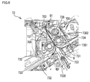
FIG. 4 is a cross-sectional view of a sheet folding device included in the post-processing device. -
FIG. 5 is a top view of a first roller, a second roller, and a blade included in the sheet folding device. -
FIG. 6 is a cross-sectional view of the sheet folding device during a two-fold process. -
FIG. 7 is a cross-sectional view of the sheet folding device during a three-fold process. -
FIG. 8 is a disassembled perspective view of a first gear coupling mechanism in the sheet folding device. -
FIG. 9 is a cross-sectional view of the first gear coupling mechanism in the sheet folding device. -
FIG. 10 is a disassembled perspective view of a second gear coupling mechanism in the sheet folding device. -
FIG. 11 is a cross-sectional view of the second gear coupling mechanism in the sheet folding device. -
FIG. 12 is a diagram showing a pair of rollers and a blade of a conventional sheet folding device in the state before the blade is inserted in a nip portion. -
FIG. 13 is a diagram showing the pair of rollers and the blade of the conventional sheet folding device in the state immediately before the blade is pulled out from the nip portion. - The following describes an embodiment of the present disclusure with reference to the attached drawings. It should be noted that the following embodiment is an example of a specific embodiment of the present disclosure and should not limit the technical scope of the present disclosure.
- First, a description is given of an outlined configuration of an
image forming apparatus 10 according to the embodiment with reference toFIG. 1 . As shown inFIG. 1 , theimage forming apparatus 10 includes amain body portion 2, a scanner 1, and apost-processing device 7. - The
image forming apparatus 10 shown inFIG. 1 is a multifunction peripheral. Theimage forming apparatus 10 may be a printer, a copier, or a facsimile apparatus. The multifunction peripheral has a plurality of functions such as functions of a printer and a copier. - Next, configurations of the scanner 1 and the
main body portion 2 are described with reference toFIG. 2 . The scanner 1 is a device that reads an image from a document sheet. When theimage forming apparatus 10 executes a copy process, themain body portion 2 forms an image on asheet member 9 based on image data of the document sheet, the image data being output from the scanner 1. - The
main body portion 2 performs an electrophotographic image formation. Themain body portion 2 includes asheet conveying portion 3, an image forming portion 4, and a fixing portion 5. It is noted that themain body portion 2 may perform an image formation by a method other than the electrophotography, such as an ink jet method. - The
sheet conveying portion 3 includes asheet receiving portion 30, asheet feed portion 31, aconveyance roller 32, and apath switching mechanism 33. A plurality ofsheet members 9 are stored in thesheet receiving portion 30 in a stacked state. It is noted that thesheet member 9 is a sheet-like image formation medium such as a sheet of paper, a sheet of coated paper, a postcard, an envelope, or an OHP sheet. Thesheet feed portion 31 feeds asheet member 9 from thesheet receiving portion 30 toward asheet conveyance path 300. - The
conveyance roller 32 conveys thesheet member 9 fed from thesheet feed portion 31, toward the image forming portion 4. Furthermore, theconveyance roller 32 conveys thesheet member 9, after an image is formed thereon, from thesheet conveyance path 300 onto adischarge tray 303 or to thepost-processing device 7. - The
path switching mechanism 33 selectively switches between two conveyance paths along which thesheet member 9 with the image formed thereon is to be conveyed. The two conveyance paths are a path from thesheet conveyance path 300 to thedischarge tray 303, and a path from thesheet conveyance path 300 to thepost-processing device 7. - The image forming portion 4 forms an image on a surface of the
sheet member 9 that is moving in thesheet conveyance path 300. In the image forming portion 4, a chargingportion 42 uniformly charges the surface of a rotatingphotoconductor 41. Furthermore, anoptical scanning portion 43 writes an electrostatic latent image on the surface of thephotoconductor 41 by scanning the surface with a laser beam. A developingporion 44 develops the electrostatic latent image by supplying developer to thephotoconductor 41. - Furthermore, in the image forming portion 4, a
transfer portion 45 transfers the image of the developer formed on the surface of thephotoconductor 41 to thesheet member 9 that is moving along thesheet conveyance path 300. - In the fixing portion 5, the
sheet member 9 with an image formed thereon is nipped between a pressure roller and a heating roller containing a heater and is fed to a downstream step. In this operation, the fixing portion 5 heats the image of the developer on thesheet member 9 and fixes the image to thesheet member 9. - Next, the configuration of the
post-processing device 7 is described with reference toFIG. 3 . Thepost-processing device 7 performs sheet processing on thesheet member 9 conveyed from themain body portion 2. The sheet processing includes processes to be performed on thesheet member 9 such as a sheet folding process. In the example shown inFIG. 3 , thepost-processing device 7 also has a function to perform a stapling process. - It is noted that the
post-processing device 7 may include a mechanism for conveying asheet member 9 set in a tray (not shown) to a position where the sheet processing is to be performed. In that case, thepost-processing device 7 can perform the sheet processing by itself, without cooperating with themain body portion 2. - The
post-processing device 7 includes aconveyance roller 70, apath switching mechanism 71, a staplingdevice 72, asheet folding device 73, afirst discharge tray 706, asecond discharge tray 708, and asheet pressing portion 707. - In the
post-processing device 7, aninlet conveyance path 700, afirst conveyance path 701, and asecond conveyance path 702 are formed to convey thesheet member 9. Furthermore, anoutlet conveyance path 703, a dead-end conveyance path 704, and abypass conveyance path 705 are formed in the downstream of thesecond conveyance path 702 in thepost-processing device 7. - The
conveyance roller 70 conveys thesheet member 9 along theinlet conveyance path 700, thefirst conveyance path 701, and thesecond conveyance path 702. Thesheet member 9 sent from themain body portion 2 to thepost-processing device 7 enters theinlet conveyance path 700. - The
path switching mechanism 71 selectively switches between two conveyance paths along which thesheet member 9 is to be conveyed after being conveyed along theinlet conveyance path 700. Of the two conveyance paths, one is thefirst conveyance path 701 and the other is thesecond conveyance path 702. Thesheet member 9 conveyed along thefirst conveyance path 701 is directly discharged to thefirst discharge tray 706 by theconveyance roller 70. - The stapling
device 72 is provided in thesecond conveyance path 702. The staplingdevice 72 includes astack tray 721 and a staplingportion 722. Thestack tray 721 stores a bundle ofsheet members 9 in the state of being aligned and positioned with respect to the staplingportion 722. - The stapling
portion 722 performs a stapling process to staple the bundle ofsheet members 9 stored in thestack tray 721. When the sheet folding process is not performed to thesheet members 9, the stapled bundle ofsheet members 9 is conveyed by theconveyance roller 70 along thesecond conveyance path 702 in a reverse direction to thefirst conveyance path 701. - On the other hand, when the sheet folding process is performed to the
sheet members 9, the stapled bundle ofsheet members 9 is conveyed by theconveyance roller 70 to thesheet folding device 73 that is on the downstream side. - In the following, a description is given of an outlined configuration of the
sheet folding device 73 with reference toFIG. 3 to FIG. 5 . Thesheet folding device 73 includes an inclinedsheet supporting portion 731, a movablesheet supporting portion 732, ablade 733, afirst roller 734, and asecond roller 735. Furthermore, thesheet folding device 73 of the present embodiment includes athird roller 736. - The
first roller 734, thesecond roller 735, and thethird roller 736 are sheet folding rollers that fold, by nipping, one ormore sheet members 9. As a result, thesheet folding device 73 can fold one ormore sheet members 9 after images are formed thereon. - The
first roller 734 and thesecond roller 735 rotate in the state where their outer circumferential surfaces contact each other. Similarly, thefirst roller 734 and thethird roller 736 rotate in the state where their outer circumferential surfaces contact each other. - In the following description, a portion between the
first roller 734 and thesecond roller 735, namely, a portion where the outer circumferential surfaces of thefirst roller 734 and thesecond roller 735 contact each other is referred to as afirst nip portion 7301. In addition, a portion between thefirst roller 734 and thethird roller 736, namely, a portion where the outer circumferential surfaces of thefirst roller 734 and thethird roller 736 contact each other is referred to as asecond nip portion 7302. - The inclined
sheet supporting portion 731 supports asheet member 9 sent via thesecond conveyance path 702, in the state where thesheet member 9 is inclined. The movablesheet supporting portion 732 includes a lowerend supporting portion 7320 configured to support the lower end of thesheet member 9 that is supported by the inclinedsheet supporting portion 731 in the inclined state. - The movable
sheet supporting portion 732 includes a mechanism that moves the lowerend supporting portion 7320 along a surface of the inclinedsheet supporting portion 731 that supports theinclined sheet member 9. When the lowerend supporting portion 7320 changes in position, thesheet member 9 supported by the inclinedsheet supporting portion 731 changes in position. - The
blade 733 is a plate-like member made of a metal such as iron or stainless steel. With an operation of adisplacement mechanism 7330, theblade 733 is displaced to strike thesheet member 9 supported by the inclinedsheet supporting portion 731, toward thefirst nip portion 7301. Thedisplacement mechanism 7330 causes theblade 733 to be reciprocally displaced between a position where it is nipped in thefirst nip portion 7301 and a position where it is away from thefirst nip portion 7301. - The
first roller 734 and thesecond roller 735 rotate in conjunction with each other in opposite directions. As a result, in thefirst nip portion 7301, the outer circumferential surfaces of thefirst roller 734 and thesecond roller 735 move in the same direction. - The
blade 733 strikes thesheet member 9 at a portion between the front end and rear end thereof toward thefirst nip portion 7301 while thesheet member 9 is supported by the inclinedsheet supporting portion 731. This allows thesheet member 9 to be folded in two and inserted into thefirst nip portion 7301. Thesheet member 9 then passes through thefirst nip portion 7301 in the folded state. - The
sheet member 9 folded by thesheet folding device 73 is sent to theoutlet conveyance path 703 and then discharged to thesecond discharge tray 708 by theconveyance roller 70. - The
sheet pressing portion 707 is supported in the state of hanging down from an upper portion of the exit of theoutlet conveyance path 703. Thesheet pressing portion 707 is configured to press, from above, thesheet member 9 discharged from theoutlet conveyance path 703. Thesheet pressing portion 707 prevents thesheet member 9 discharged from theoutlet conveyance path 703 from interfering with the next discharging of asheet member 9. -
FIG. 5 is a diagram showing thefirst roller 734, thesecond roller 735, and theblade 733 individually. - As shown in
FIG. 5 , thefirst roller 734 includes alarge diameter portion 7341 at a center thereof in the longitudical direction, wherein thelarge diameter portion 7341 is slightly larger in outer diameter than portions on both sides thereof. Similarly, thesecond roller 735 includes alarge diameter portion 7351 at a center thereof in the longitudical direction, wherein thelarge diameter portion 7351 is slightly larger in outer diameter than portions on both sides thereof. With this configuration, thelarge diameter portion 7341 of thefirst roller 734 and thelarge diameter portion 7351 of thesecond roller 735 closely contact each other. - Hereinafter, the portions of the
first roller 734 located on both sides of thelarge diameter portion 7341 are referred to assmall diameter portions 7342. Similarly, the portions of thesecond roller 735 located on both sides of thelarge diameter portion 7351 are referred to assmall diameter portions 7352. As one example, thelarge diameter portion small diameter portions - It is noted that although not shown, as with the
second roller 735, thethird roller 736 includes a large diameter portion and small diameter portions. Furthermore, as with asecond shaft portion 7350, a shaft portion of thethird roller 736 is coupled with a gear. When a power is transmitted to the gear, thethird roller 736 is rotated in conjunction with thefirst roller 734. - The
large diameter portion small diameter portions sheet member 9 passing through thefirst nip portion 7301. As a result, paper wrinkles are less likely to be generated on thesheet member 9 when it passes through thefirst nip portion 7301. - The
first roller 734 includes afirst shaft portion 7340, and thesecond roller 735 includes asecond shaft portion 7350, wherein thefirst shaft portion 7340 and thesecond shaft portion 7350 are rotation shafts. Thefirst shaft portion 7340 is coupled with afirst gear 734g. Thesecond shaft portion 7350 is coupled with asecond gear 735g. Thefirst gear 734g and thesecond gear 735g receive a driving force from a driving source (not shown) via another gear (not shown). This allows thefirst gear 734g and thesecond gear 735g to rotate in conjunction with each other. - When the
first gear 734g rotates, thefirst shaft portion 7340 and thefirst roller 734 rotate. Similarly, when thesecond gear 735g rotates, thesecond shaft portion 7350 and thesecond roller 735 rotate. - In addition, the
blade 733 includes acenter protruding portion 7331 in a part of a front-end portion of theblade 733 that corresponds to thelarge diameter portion first roller 734 and thesecond roller 735, thecenter protruding portion 7331 protruding frontward relative to portions on both sides thereof. - In the example shown in
FIG. 5 , in the part of the front-end portion of theblade 733 that corresponds to thelarge diameter portion first roller 734 and thesecond roller 735, the central portion is thecenter protruding portion 7331 and the remaining portions are a pair ofconcave portions 7332. The pair ofconcave portions 7332 are more concave than end portions of theblade 733 that are located on both sides of the pair ofconcave portions 7332 in the longitudinal direction. - When the
blade 733 is pulled out from thefirst nip portion 7301, the pair ofconcave portions 7332 play a role of reducing friction resistance between theblade 733 and thesheet member 9 nipped between thelarge diameter portions - In the present embodiment, the
sheet folding device 73 can execute a two-fold process and a three-fold process, wherein in the two-fold process, thesheet member 9 is folded in two, and in the three-fold process, thesheet member 9 is folded in three. In the following, the two-fold process and the three-fold process are described with reference toFIG. 6 andFIG. 7 . - The
sheet folding device 73 includes a movable sheet-guidingportion 737 configured to guide the traveling direction of asheet member 9 fed out from thefirst nip portion 7301 toward the downstream. The movable sheet-guidingportion 737 is movably supported by a displacement mechanism (not shown). - As shown in
FIG. 6 , in the two-fold process, the movable sheet-guidingportion 737 is positioned to a first position. This allows the entrance of theoutlet conveyance path 703 to be opened, and the entrance of the dead-end conveyance path 704 to be closed. - The movable sheet-guiding
portion 737 at the first position guides thesheet member 9 fed out from thefirst nip portion 7301 to theoutlet conveyance path 703. This allows thesheet member 9 folded in two by thefirst roller 734 and thesecond roller 735 to be discharged to thesecond discharge tray 708 from theoutlet conveyance path 703. - As shown in
FIG. 7 , in the three-fold process, the movable sheet-guidingportion 737 is positioned to a second position. This allows the entrance of theoutlet conveyance path 703 to be closed, and the entrance of the dead-end conveyance path 704 to be opened. - The movable sheet-guiding
portion 737 at the second position guides thesheet member 9 fed out from thefirst nip portion 7301 to the dead-end conveyance path 704. This allows thesheet member 9 that has been folded in two to enter the dead-end conveyance path 704, with afirst folding line 91 formed by thefirst nip portion 7301 in front. - The dead-
end conveyance path 704 is provided on an opposite side of thesecond roller 735 with respect to theblade 733, and forms a dead-end path for thesheet member 9. - First, the movable sheet-guiding
portion 737 guides a part of thesheet member 9 that has passed through thefirst nip portion 7301, to the dead-end conveyance path 704. This allows thesheet member 9 folded in two to be conveyed along the dead-end conveyance path 704 until thefirst folding line 91 reaches the innermost part of the dead-end conveyance path 704. - Next, as shown in
FIG. 7 , after thefirst folding line 91 reaches the innermost part of the dead-end conveyance path 704, the movable sheet-guidingportion 737 guides the remaining part of thesheet member 9 that has passed through thefirst nip portion 7301, to thesecond nip portion 7302. It is noted that the movable sheet-guidingportion 737 is an example of the sheet guiding portion of the present disclosure. - The
sheet member 9 guided to thesecond nip portion 7302 is nipped by thefirst roller 734 and thethird roller 736. Thesheet member 9 is passed through thesecond nip portion 7302 while being nipped by thefirst roller 734 and thethird roller 736, and is fed out from thesecond nip portion 7302 toward the downstream. This allows thefirst roller 734 and thethird roller 736 to form, on thesheet member 9, asecond folding line 92 that is different from thefirst folding line 91. - The
bypass conveyance path 705 is a conveyance path that extends from the downstream of thesecond nip portion 7302 and merges with the middle of theoutlet conveyance path 703. Thesheet member 9, after being fed out from thesecond nip portion 7302, enters thebypass conveyance path 705. - The
sheet member 9 that has entered thebypass conveyance path 705 is conveyed along thebypass conveyance path 705 and enters the middle of theoutlet conveyance path 703 and then discharged to thesecond discharge tray 708 by theconveyance roller 70. This allows thesheet member 9 folded in three to be discharged to thesecond discharge tray 708. - The movable
sheet supporting portion 732 sets the position of the lowerend supporting portion 7320 based on the size of thesheet member 9 and sets which of the two-fold process or the three-fold process is performed on thesheet member 9. - The entrance of the
outlet conveyance path 703 is approximately located on a line extending from the front end of theblade 733. On the other hand, the entrance of the dead-end conveyance path 704 is more on thesecond roller 735 side than the line extending from the front end of theblade 733. In addition, thefirst roller 734 rotates at a peripheral speed slightly higher than that of thesecond roller 735. - In the present embodiment, the gear ratios of the
first gear 734g and thesecond gear 735g to the gear (not shown) of the driving side are the same. As a result, the rotation speeds of thefirst roller 734 and thesecond roller 735 are the same. In addition, thefirst roller 734 is slightly larger than thesecond roller 735 in diameter. This enables thefirst roller 734 to rotate at a peripheral speed slightly higher than that of thesecond roller 735. - A ratio between the peripheral speed of the
first roller 734 and the peripheral speed of thesecond roller 735 is set such that thesheet member 9 fed out from thefirst nip portion 7301 moves toward the middle of the entrance of theoutlet conveyance path 703 and the entrance of the dead-end conveyance path 704. This facilitates the movable sheet-guidingportion 737 to guide thesheet member 9 either to theoutlet conveyance path 703 or to the dead-end conveyance path 704. - Meanwhile, a gear coupling mechanism including a parallel pin may be adopted as a mechanism for coupling the
first gear 734g and thesecond gear 735g with thefirst shaft portion 7340 and thesecond shaft portion 7350 of thefirst roller 734 and thesecond roller 735 for the sheet folding process, respectively. - More specifically, a first
gear coupling mechanism 81 as shown inFIG. 8 andFIG. 9 may be adopted as a mechanism for coupling thefirst gear 734g with thefirst shaft portion 7340 of thefirst roller 734. - The first
gear coupling mechanism 81 includes a firstparallel pin 811; a first pin through-hole 812 formed in thefirst shaft portion 7340, and a first shaft through-hole 814 and afirst groove 815 formed in thefirst gear 734g. The first pin through-hole 812 is a through hole extending in a direction perpendicular to the longitudinal direction of thefirst shaft portion 7340. In addition, the first shaft through-hole 814 is a through hole that extends along the rotation center line of thefirst gear 734g. - The first
parallel pin 811 made of metal is passed through the first pin through-hole 812 of thefirst shaft portion 7340 and is inserted in thefirst groove 815 formed in thefirst gear 734g that is made of synthetic resin. In this case, a small gap is generated between the firstparallel pin 811 and the inner side surface of the first pin through-hole 812 of thefirst shaft portion 7340, and a small gap is also generated between the firstparallel pin 811 and the inner side surface of thefirst groove 815 of thefirst gear 734g. These gaps become plays for transmission of a rotative force from thefirst gear 734g to thefirst roller 734. - In the case where the configuration of the first
gear coupling mechanism 81 is adopted also as a mechanism for coupling thesecond gear 735g with thesecond shaft portion 7350 of thesecond roller 735, a trouble occurs that paper wrinkles are likely to be generated on thesheet member 9, as described in the following. - That is, when the
first roller 734 and thesecond roller 735 have different peripheral speeds,looseness 93 is likely to be generated on a part of thesheet member 9 that has passed through thefirst nip portion 7301, due to a play of the firstgear coupling mechanism 81 including the first parallel pin 811 (seeFIG. 13 ). - More specifically, among portions of the
sheet member 9 folded in two, thelooseness 93 is likely to be generated in a portion on the side of thefirst roller 734 that has a higher peripheral speed. Thelooseness 93 becomes a cause of the paper wrinkles that are generated when theblade 733 is pulled out from thefirst nip portion 7301. -
FIG. 12 andFIG. 13 are diagrams showing a pair ofrollers blade 733 included in a conventional sheet folding device. In the conventional sheet folding device, the firstgear coupling mechanism 81 is adopted both as a mechanism for coupling thefirst gear 734g with thefirst shaft portion 7340 of thefirst roller 734, and as a mechanism for coupling thesecond gear 735g with thesecond shaft portion 7350 of thesecond roller 735. -
FIG. 12 shows a state before theblade 733 is inserted in thefirst nip portion 7301.FIG. 13 shows a state immediately before theblade 733 is pulled out from thefirst nip portion 7301. - As shown in
FIG. 12 andFIG. 13 , in thefirst roller 734 having a higher peripheral speed, thefirst gear 734g always rotates prior to thefirst shaft portion 7340. On the other hand, in thesecond roller 735 having a lower peripheral speed, thesecond gear 735g may or may not rotate prior to thesecond shaft portion 7350. - For example, as shown in
FIG. 12 , in the state before theblade 733 is inserted in thefirst nip portion 7301, since thesecond roller 735 rotates together with thefirst roller 734, thesecond shaft portion 7350 rotates prior to thesecond gear 735g. - On the other hand, in the state where the
sheet member 9 and theblade 733 are inserted in thefirst nip portion 7301, power is not transmitted to the outer circumferential surface of thesecond roller 735 from the outer circumferential surface of thefirst roller 734. As a result, thesecond gear 735g idles due to the play of the firstgear coupling mechanism 81, and during the idling period, the rotation of thesecond roller 735 temporarily stops. As a result, as shown inFIG. 13 , thelooseness 93 is generated in thesheet member 9. - If the
blade 733 is pulled out from thefirst nip portion 7301 in the state where thelooseness 93 is generated in thesheet member 9, paper wrinkles are likely to be generated on a portion of thesheet member 9 that has been in contact with theblade 733. In particular, paper wrinkles are likely to be generated on a portion of thesheet member 9 that has been in contact with thecenter protruding portion 7331 of theblade 733. - In the
sheet folding device 73 of the present embodiment, a secondgear coupling mechanism 82 described below couples thesecond gear 735g with thesecond shaft portion 7350 of thesecond roller 735. This configuration prevents paper wrinkles from being generated on asheet member 9 due to a play of the mechanism that couples thegear shaft portion rollers sheet member 9. -
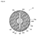
FIG. 10 is a disassembled perspective view of the secondgear coupling mechanism 82.FIG. 11 is a cross-sectional view of the secondgear coupling mechanism 82. - Similar to the first
gear coupling mechanism 81, the secondgear coupling mechanism 82 includes a secondparallel pin 821, a second pin through-hole 822 formed in thesecond shaft portion 7350, and a second shaft through-hole 824 and asecond groove 825 formed in thesecond gear 735g. The second pin through-hole 822 extends in a direction perpendicular to the longitudinal direction of thesecond shaft portion 7350. In addition, the second shaft through-hole 824 extends along the rotation center line of thesecond gear 735g. - In the second
gear coupling mechanism 82,projection portions 826 are formed on a side wall which is one of opposite inner side walls of thesecond groove 825, such that top parts of theprojection portions 826 can closely contact the secondparallel pin 821. This is a different point from the firstgear coupling mechanism 81. In the present embodiment, twoprojection portions 826 are respectively formed on both sides of the second shaft through-hole 824 in thesecond groove 825. That is, theprojection portions 826 provided on one inner side wall of thesecond groove 825, project from both sides of thesecond shaft portion 7350 toward the secondparallel pin 821. The top parts of theprojection portions 826 located on both sides of thesecond shaft portion 7350 closely contact the secondparallel pin 821 from the same direction. That is, parallel forces act, in the same direction, on the secondparallel pin 821 from theprojection portions 826. In the example shown inFIG. 10 , theprojection portions 826 are ribs formed along the depth direction of thesecond groove 825. - The second
parallel pin 821 made of metal is passed through the second pin through-hole 822 of thesecond shaft portion 7350 and is inserted in thesecond groove 825 formed in thesecond gear 735g that is made of synthetic resin. As shown inFIG. 11 , theprojection portions 826 cause the secondparallel pin 821 to closely contact a side wall that is, in thesecond groove 825, opposite to the side wall on which theprojection portions 826 are formed, and cause the secondparallel pin 821 to closely contact a portion of the second pin through-hole 822 of thesecond shaft portion 7350 that is on an opposite side with respect to theprojection portions 826. - As shown in
FIG. 11 ,first areas 8261 are areas at which the outer circumferential surface of the secondparallel pin 821 closely contacts the inner side wall of thesecond groove 825. In addition, asecond area 8262 is an area at which the outer circumferential surface of the secondparallel pin 821 closely contacts the inner surface of the second pin through-hole 822. - When the second
parallel pin 821 is inserted in thesecond groove 825, theprojection portions 826 made of synthetic resin slightly contract due to a pressure from the secondparallel pin 821. This allows the top parts of theprojection portions 826 to closely contact the outer circumferential surface of the secondparallel pin 821, and further allows the close contact state in thefirst areas 8261 and thesecond area 8262 to be maintained. - According to the present embodiment, by the action of the
projection portions 826, the play for the transmission of a rotative force from thesecond gear 735g to thesecond roller 735 can be eliminated. In this case, in thesheet member 9 folded in two by thefirst nip portion 7301, thelooseness 93 is not generated in a portion on the side of thefirst roller 734 having a higher peripheral speed. This makes it possible to prevent paper wrinkles from being generated on thesheet member 9 when theblade 733 is pulled out from thefirst nip portion 7301. - In addition, the
projection portions 826 have a simple configuration, and it is easy to form theprojection portions 826 on thesecond gear 735g made of synthetic resin. - In addition, in the first
gear coupling mechanism 81, the firstparallel pin 811 is inserted in thefirst groove 815 of thefirst gear 734g with a play therebetween. Furthermore, the firstparallel pin 811 is inserted in the first pin through-hole 812 of thefirst shaft portion 7340 with a play therebetween. - As described above, in the
first roller 734 having a higher peripheral speed, if the firstgear coupling mechanism 81 has a play, the play itself does not become a cause of thelooseness 93 or paper wrinkles of thesheet member 9. Rather, the play of the firstgear coupling mechanism 81 is convenient for removing a paper jam of thesheet member 9 in thefirst nip portion 7301, for example. - In addition, in the
sheet folding device 73 that can execute the three-fold process, thesheet member 9 that has passed through thefirst nip portion 7301 needs to be guided to the dead-end conveyance path 704 that is closer to thesecond roller 735. As a result, it is necessary to set the peripheral speed of thefirst roller 734 to be higher than the peripheral speed of thesecond roller 735. In such a case, the effect produced by the secondgear coupling mechanism 82 of preventing paper wrinkles from being generated on thesheet member 9 becomes more evident. - In the second
gear coupling mechanism 82 shown inFIG. 10 andFIG. 11 , a plurality ofprojection portions 826 may be provided on each of both sides of the second shaft through-hole 824 in thesecond groove 825. - In the
sheet folding device 73, the gear ratios of thefirst gear 734g and thesecond gear 735g to the gear (not shown) of the driving side may be different. This enables the peripheral speed of thefirst roller 734 to be higher than the peripheral speed of thesecond roller 735 even when thefirst roller 734 and thesecond roller 735 have the same outer diameter. - In the
sheet folding device 73, thethird roller 736 may be formed as a cylinder of uniform diameter, without the large diameter portion and the small diameter portions. - It is noted that the sheet folding device, the post-processing device, the image forming apparatus, and the gear coupling mechanism of the present disclosure may be configured by, within the scope of claims, freely combining the above-described embodiments and application examples, or by modifying the embodiment and application examples or omitting a part thereof.
- It is to be understood that the embodiments herein are illustrative and not restrictive, since the scope of the disclosure is defined by the appended claims rather than by the description preceding them, and all changes that fall within metes and bounds of the claims, or equivalence of such metes and bounds thereof are therefore intended to be embraced by the claims.
Claims (4)
- A sheet folding device (73) comprising:a first roller (734) and a second roller (735) configured to rotate in a state where outer circumferential surfaces thereof contact each other;a plate-like blade (733) configured to strike a sheet member toward a nip portion (7301, 7302) between the first roller (734) and the second roller (735);a first parallel pin (811) passed through a first pin through-hole (812) that penetrates through a first shaft portion (7340) in a direction perpendicular to a longitudinal direction of the first shaft portion (7340), the first shaft portion (7340) being a rotation shaft of the first roller (734);a first gear (734g) having a first shaft through-hole (814) and a first groove (815), the first shaft portion (7340) being passed through the first shaft through-hole (814), the first parallel pin (811) passed through the first shaft portion (7340) being inserted in the first groove (815);a second parallel pin (821) passed through a second pin through-hole (822) that penetrates through a second shaft portion (7350) in a direction perpendicular to a longitudinal direction of the second shaft portion (7350), the second shaft portion (7350) being a rotation shaft of the second roller (735); anda second gear (735g) having a second shaft through-hole (824) and a second groove (825), the second shaft portion (7350) being passed through the second shaft through-hole (824), the second parallel pin (821) passed through the second shaft portion (7350) being inserted in the second groove (825), whereinthe blade (733) strikes the sheet member such that the sheet member is folded in two and inserted in the nip portion (7301, 7302),the first gear (734g) and the second gear (735g) rotate in conjunction with each other,the first roller (734) rotates at a higher peripheral speed than the second roller (735),projection portions (826) are formed on a side wall which is one of opposite inner side walls of the second groove (825), in such a way as to project from both sides of the second shaft portion (7350) toward the second parallel pin (821), andthe projection portions (826) cause the second parallel pin (821) to closely contact a side wall that is, in the second groove (825), opposite to the side wall on which the projection portions (826) are formed, and cause the second parallel pin (821) to closely contact a portion of the second pin through-hole (822) that is on an opposite side with respect to the projection portions (826).
- The sheet folding device (73) according to claim 1, wherein
the first parallel pin (811) is inserted in the first groove (815) with a play therebetween. - The sheet folding device (73) according to claim 1 or 2, wherein
the first roller (734) and the second roller (735) each include a large diameter portion (7341, 7351) at a center thereof in a longitudical direction, the large diameter portion (7341, 7351) being slightly larger in outer diameter than portions on both sides thereof, and
the blade (733) includes a protruding portion (7331) in a part of a front-end portion of the blade (733) that corresponds to the large diameter portion (7341, 7351), the protruding portion (7331) protruding frontward relative to portions on both sides thereof. - The sheet folding device (73) according to any one of claims 1 to 3 further comprising.
a third roller (736) configured to rotate in a state where an outer circumferential surface thereof contacts an outer circumferential surface of the first roller (734);
a dead-end conveyance path provided on an opposite side of the second roller (735) with respect to the blade (733), and forming a dead-end path for the sheet member; and
a sheet guiding portion (737) configured to guide a part of the sheet member that has passed through a first nip portion (7301, 7302) between the first roller (734) and the second roller (735), to the dead-end conveyance path, and after the sheet member reaches an innermost part of the dead-end conveyance path, guide a remaining part of the sheet member that has passed through the first nip portion (7301, 7302), to a second nip portion (7301, 7302) between the first roller (734) and the third roller (736), wherein
the first roller (734) and the third roller (736) cause the sheet member to be passed through and fed out from the second nip portion (7301, 7302) while being nipped by the first roller (734) and the third roller (736), thereby forming, on the sheet member, a second folding line (92) that is different from a first folding line (91) formed by the first nip portion (7301, 7302).
Applications Claiming Priority (1)
| Application Number | Priority Date | Filing Date | Title |
|---|---|---|---|
| JP2015119068A JP6269584B2 (en) | 2015-06-12 | 2015-06-12 | Sheet folding apparatus, image forming apparatus, and gear coupling mechanism |
Publications (2)
| Publication Number | Publication Date |
|---|---|
| EP3103746A1 true EP3103746A1 (en) | 2016-12-14 |
| EP3103746B1 EP3103746B1 (en) | 2017-10-11 |
Family
ID=56116199
Family Applications (1)
| Application Number | Title | Priority Date | Filing Date |
|---|---|---|---|
| EP16169144.9A Active EP3103746B1 (en) | 2015-06-12 | 2016-05-11 | Sheet folding device |
Country Status (4)
| Country | Link |
|---|---|
| US (1) | US9606492B2 (en) |
| EP (1) | EP3103746B1 (en) |
| JP (1) | JP6269584B2 (en) |
| CN (1) | CN106241478B (en) |
Families Citing this family (2)
| Publication number | Priority date | Publication date | Assignee | Title |
|---|---|---|---|---|
| JP2018184973A (en) * | 2017-04-24 | 2018-11-22 | キヤノン株式会社 | Drive transmission device |
| JP2025019688A (en) * | 2023-07-28 | 2025-02-07 | 京セラドキュメントソリューションズ株式会社 | Gear coupling structure, drive device and image forming device |
Citations (3)
| Publication number | Priority date | Publication date | Assignee | Title |
|---|---|---|---|---|
| JPH07133861A (en) * | 1993-11-10 | 1995-05-23 | Ricoh Co Ltd | Rotation restriction structure of shaft mounting member |
| US20050196210A1 (en) * | 2004-03-02 | 2005-09-08 | Tomoo Suzuki | Recording medium transport device |
| US20150119223A1 (en) * | 2013-10-30 | 2015-04-30 | Kyocera Document Solutions Inc. | Sheet folding apparatus and sheet post-processing apparatus |
Family Cites Families (19)
| Publication number | Priority date | Publication date | Assignee | Title |
|---|---|---|---|---|
| US1273952A (en) * | 1915-10-07 | 1918-07-30 | Packard Motor Car Co | Vibration-damping device. |
| US2060376A (en) * | 1935-12-02 | 1936-11-10 | William A Jex | One-way clutch |
| US3566497A (en) * | 1968-08-19 | 1971-03-02 | Edmund Lorne Hamlen | Conveyor roller |
| JPH063214B2 (en) * | 1985-08-21 | 1994-01-12 | 東京電気株式会社 | Rotation transmission device |
| US4902162A (en) * | 1988-04-19 | 1990-02-20 | Emerson Electric Co. | Shaft and rotatable machine element assembly |
| JPH01158843U (en) * | 1988-04-22 | 1989-11-02 | ||
| US5398618A (en) * | 1991-02-26 | 1995-03-21 | Vfv Polymers Pty. Ltd. | Conveyor trolley wheel assembly |
| US5117970A (en) * | 1991-06-19 | 1992-06-02 | Asgco Manufacturing, Inc. | Idler roller sleeve |
| WO2001032537A1 (en) * | 1999-11-02 | 2001-05-10 | Rollerbrake (Pty) Ltd. | Conveyor idler |
| US7771333B2 (en) * | 2001-02-06 | 2010-08-10 | Advanced Aircraft Roller Systems, Inc. | Conveyor roller system |
| US7871065B2 (en) | 2007-01-31 | 2011-01-18 | Nisca Corporation | Sheet feeding device and post-processing apparatus and image forming system comprising the same |
| JP4861877B2 (en) * | 2007-03-29 | 2012-01-25 | ニスカ株式会社 | Sheet folding apparatus, post-processing apparatus including the same, and image forming system |
| JP4840217B2 (en) * | 2007-03-27 | 2011-12-21 | ブラザー工業株式会社 | bearing |
| US8430801B2 (en) * | 2008-04-22 | 2013-04-30 | Advanced Aircraft Roller Systems, Inc. | Lightweight conveyor roller |
| JP5308964B2 (en) * | 2009-08-31 | 2013-10-09 | 京セラドキュメントソリューションズ株式会社 | Drive transmission mechanism and image forming apparatus having the same |
| JP5805302B2 (en) * | 2012-03-22 | 2015-11-04 | 京セラドキュメントソリューションズ株式会社 | Folding device, post-processing device and image forming apparatus |
| ITRM20120452A1 (en) * | 2012-09-20 | 2014-03-21 | Artecon Sagl D | ROLLER CONVEYOR SYSTEM. |
| JP5798997B2 (en) * | 2012-10-10 | 2015-10-21 | 京セラドキュメントソリューションズ株式会社 | Sheet folding apparatus, sheet post-processing apparatus including the same, and image forming apparatus |
| JP6007742B2 (en) * | 2012-11-16 | 2016-10-12 | 株式会社リコー | Paper processing apparatus, image forming system, and paper folding method |
-
2015
- 2015-06-12 JP JP2015119068A patent/JP6269584B2/en active Active
-
2016
- 2016-05-10 CN CN201610304734.8A patent/CN106241478B/en active Active
- 2016-05-11 EP EP16169144.9A patent/EP3103746B1/en active Active
- 2016-05-17 US US15/157,299 patent/US9606492B2/en active Active
Patent Citations (3)
| Publication number | Priority date | Publication date | Assignee | Title |
|---|---|---|---|---|
| JPH07133861A (en) * | 1993-11-10 | 1995-05-23 | Ricoh Co Ltd | Rotation restriction structure of shaft mounting member |
| US20050196210A1 (en) * | 2004-03-02 | 2005-09-08 | Tomoo Suzuki | Recording medium transport device |
| US20150119223A1 (en) * | 2013-10-30 | 2015-04-30 | Kyocera Document Solutions Inc. | Sheet folding apparatus and sheet post-processing apparatus |
Also Published As
| Publication number | Publication date |
|---|---|
| JP6269584B2 (en) | 2018-01-31 |
| EP3103746B1 (en) | 2017-10-11 |
| CN106241478A (en) | 2016-12-21 |
| CN106241478B (en) | 2018-01-02 |
| US20160363900A1 (en) | 2016-12-15 |
| US9606492B2 (en) | 2017-03-28 |
| JP2017001846A (en) | 2017-01-05 |
Similar Documents
| Publication | Publication Date | Title |
|---|---|---|
| US7794381B2 (en) | Z-folding apparatus and sheet processing apparatus | |
| US9738473B2 (en) | Sheet detecting apparatus, sheet conveying apparatus, and image forming apparatus | |
| JP2009029523A (en) | Folding device, device provided with the same, and folding method | |
| JP6227602B2 (en) | Sheet stacking device | |
| KR102002673B1 (en) | Sheet conveying device and image forming apparatus | |
| US10538411B2 (en) | Sheet conveying device | |
| US7954796B2 (en) | Sheet processing apparatus | |
| JP5306025B2 (en) | Sheet conveying apparatus and electrophotographic apparatus | |
| US9606492B2 (en) | Sheet folding device, image forming apparatus and gear coupling mechanism | |
| JP2011126686A (en) | Sheet supply device and image forming device | |
| JP6984188B2 (en) | Image forming device | |
| EP3219653A1 (en) | Sheet post-processing device and image forming system equipped with same | |
| JP4445899B2 (en) | Paper folding apparatus and image forming apparatus | |
| JP2018052706A (en) | Sheet conveying apparatus, image forming apparatus, and image reading apparatus | |
| JP2017081665A (en) | Post-processing device and image formation apparatus | |
| JP7750675B2 (en) | Sheet processing apparatus and image forming system | |
| JP4239889B2 (en) | Paper post-processing device | |
| JP2023004461A (en) | Sheet processing device and image formation system | |
| JP2023122999A (en) | Sheet processing device and image formation system | |
| JP2017013979A (en) | Sheet post-processing apparatus and image forming system including the same | |
| JP2022137968A (en) | Document reading device and image forming device | |
| JPH11143281A (en) | Image forming device | |
| JP2009035398A (en) | Sheet conveying apparatus and image forming apparatus | |
| JP2001316022A (en) | Curl sheet correction device and image forming apparatus provided with this curl sheet correction device | |
| JP2014043290A (en) | Sheet processing device and image formation device |
Legal Events
| Date | Code | Title | Description |
|---|---|---|---|
| PUAI | Public reference made under article 153(3) epc to a published international application that has entered the european phase |
Free format text: ORIGINAL CODE: 0009012 |
|
| AK | Designated contracting states |
Kind code of ref document: A1 Designated state(s): AL AT BE BG CH CY CZ DE DK EE ES FI FR GB GR HR HU IE IS IT LI LT LU LV MC MK MT NL NO PL PT RO RS SE SI SK SM TR |
|
| AX | Request for extension of the european patent |
Extension state: BA ME |
|
| 17P | Request for examination filed |
Effective date: 20170123 |
|
| RBV | Designated contracting states (corrected) |
Designated state(s): AL AT BE BG CH CY CZ DE DK EE ES FI FR GB GR HR HU IE IS IT LI LT LU LV MC MK MT NL NO PL PT RO RS SE SI SK SM TR |
|
| GRAP | Despatch of communication of intention to grant a patent |
Free format text: ORIGINAL CODE: EPIDOSNIGR1 |
|
| INTG | Intention to grant announced |
Effective date: 20170426 |
|
| GRAS | Grant fee paid |
Free format text: ORIGINAL CODE: EPIDOSNIGR3 |
|
| GRAA | (expected) grant |
Free format text: ORIGINAL CODE: 0009210 |
|
| AK | Designated contracting states |
Kind code of ref document: B1 Designated state(s): AL AT BE BG CH CY CZ DE DK EE ES FI FR GB GR HR HU IE IS IT LI LT LU LV MC MK MT NL NO PL PT RO RS SE SI SK SM TR |
|
| REG | Reference to a national code |
Ref country code: GB Ref legal event code: FG4D |
|
| REG | Reference to a national code |
Ref country code: CH Ref legal event code: EP |
|
| REG | Reference to a national code |
Ref country code: IE Ref legal event code: FG4D |
|
| REG | Reference to a national code |
Ref country code: AT Ref legal event code: REF Ref document number: 935816 Country of ref document: AT Kind code of ref document: T Effective date: 20171115 |
|
| REG | Reference to a national code |
Ref country code: DE Ref legal event code: R096 Ref document number: 602016000539 Country of ref document: DE |
|
| REG | Reference to a national code |
Ref country code: NL Ref legal event code: MP Effective date: 20171011 |
|
| REG | Reference to a national code |
Ref country code: LT Ref legal event code: MG4D |
|
| REG | Reference to a national code |
Ref country code: AT Ref legal event code: MK05 Ref document number: 935816 Country of ref document: AT Kind code of ref document: T Effective date: 20171011 |
|
| PG25 | Lapsed in a contracting state [announced via postgrant information from national office to epo] |
Ref country code: NL Free format text: LAPSE BECAUSE OF FAILURE TO SUBMIT A TRANSLATION OF THE DESCRIPTION OR TO PAY THE FEE WITHIN THE PRESCRIBED TIME-LIMIT Effective date: 20171011 |
|
| REG | Reference to a national code |
Ref country code: FR Ref legal event code: PLFP Year of fee payment: 3 |
|
| PG25 | Lapsed in a contracting state [announced via postgrant information from national office to epo] |
Ref country code: LT Free format text: LAPSE BECAUSE OF FAILURE TO SUBMIT A TRANSLATION OF THE DESCRIPTION OR TO PAY THE FEE WITHIN THE PRESCRIBED TIME-LIMIT Effective date: 20171011 Ref country code: FI Free format text: LAPSE BECAUSE OF FAILURE TO SUBMIT A TRANSLATION OF THE DESCRIPTION OR TO PAY THE FEE WITHIN THE PRESCRIBED TIME-LIMIT Effective date: 20171011 Ref country code: NO Free format text: LAPSE BECAUSE OF FAILURE TO SUBMIT A TRANSLATION OF THE DESCRIPTION OR TO PAY THE FEE WITHIN THE PRESCRIBED TIME-LIMIT Effective date: 20180111 Ref country code: ES Free format text: LAPSE BECAUSE OF FAILURE TO SUBMIT A TRANSLATION OF THE DESCRIPTION OR TO PAY THE FEE WITHIN THE PRESCRIBED TIME-LIMIT Effective date: 20171011 Ref country code: SE Free format text: LAPSE BECAUSE OF FAILURE TO SUBMIT A TRANSLATION OF THE DESCRIPTION OR TO PAY THE FEE WITHIN THE PRESCRIBED TIME-LIMIT Effective date: 20171011 |
|
| PG25 | Lapsed in a contracting state [announced via postgrant information from national office to epo] |
Ref country code: GR Free format text: LAPSE BECAUSE OF FAILURE TO SUBMIT A TRANSLATION OF THE DESCRIPTION OR TO PAY THE FEE WITHIN THE PRESCRIBED TIME-LIMIT Effective date: 20180112 Ref country code: HR Free format text: LAPSE BECAUSE OF FAILURE TO SUBMIT A TRANSLATION OF THE DESCRIPTION OR TO PAY THE FEE WITHIN THE PRESCRIBED TIME-LIMIT Effective date: 20171011 Ref country code: RS Free format text: LAPSE BECAUSE OF FAILURE TO SUBMIT A TRANSLATION OF THE DESCRIPTION OR TO PAY THE FEE WITHIN THE PRESCRIBED TIME-LIMIT Effective date: 20171011 Ref country code: IS Free format text: LAPSE BECAUSE OF FAILURE TO SUBMIT A TRANSLATION OF THE DESCRIPTION OR TO PAY THE FEE WITHIN THE PRESCRIBED TIME-LIMIT Effective date: 20180211 Ref country code: LV Free format text: LAPSE BECAUSE OF FAILURE TO SUBMIT A TRANSLATION OF THE DESCRIPTION OR TO PAY THE FEE WITHIN THE PRESCRIBED TIME-LIMIT Effective date: 20171011 Ref country code: BG Free format text: LAPSE BECAUSE OF FAILURE TO SUBMIT A TRANSLATION OF THE DESCRIPTION OR TO PAY THE FEE WITHIN THE PRESCRIBED TIME-LIMIT Effective date: 20180111 Ref country code: AT Free format text: LAPSE BECAUSE OF FAILURE TO SUBMIT A TRANSLATION OF THE DESCRIPTION OR TO PAY THE FEE WITHIN THE PRESCRIBED TIME-LIMIT Effective date: 20171011 |
|
| REG | Reference to a national code |
Ref country code: DE Ref legal event code: R097 Ref document number: 602016000539 Country of ref document: DE |
|
| PG25 | Lapsed in a contracting state [announced via postgrant information from national office to epo] |
Ref country code: DK Free format text: LAPSE BECAUSE OF FAILURE TO SUBMIT A TRANSLATION OF THE DESCRIPTION OR TO PAY THE FEE WITHIN THE PRESCRIBED TIME-LIMIT Effective date: 20171011 Ref country code: CZ Free format text: LAPSE BECAUSE OF FAILURE TO SUBMIT A TRANSLATION OF THE DESCRIPTION OR TO PAY THE FEE WITHIN THE PRESCRIBED TIME-LIMIT Effective date: 20171011 Ref country code: EE Free format text: LAPSE BECAUSE OF FAILURE TO SUBMIT A TRANSLATION OF THE DESCRIPTION OR TO PAY THE FEE WITHIN THE PRESCRIBED TIME-LIMIT Effective date: 20171011 Ref country code: SK Free format text: LAPSE BECAUSE OF FAILURE TO SUBMIT A TRANSLATION OF THE DESCRIPTION OR TO PAY THE FEE WITHIN THE PRESCRIBED TIME-LIMIT Effective date: 20171011 |
|
| PLBE | No opposition filed within time limit |
Free format text: ORIGINAL CODE: 0009261 |
|
| STAA | Information on the status of an ep patent application or granted ep patent |
Free format text: STATUS: NO OPPOSITION FILED WITHIN TIME LIMIT |
|
| PG25 | Lapsed in a contracting state [announced via postgrant information from national office to epo] |
Ref country code: SM Free format text: LAPSE BECAUSE OF FAILURE TO SUBMIT A TRANSLATION OF THE DESCRIPTION OR TO PAY THE FEE WITHIN THE PRESCRIBED TIME-LIMIT Effective date: 20171011 Ref country code: PL Free format text: LAPSE BECAUSE OF FAILURE TO SUBMIT A TRANSLATION OF THE DESCRIPTION OR TO PAY THE FEE WITHIN THE PRESCRIBED TIME-LIMIT Effective date: 20171011 Ref country code: IT Free format text: LAPSE BECAUSE OF FAILURE TO SUBMIT A TRANSLATION OF THE DESCRIPTION OR TO PAY THE FEE WITHIN THE PRESCRIBED TIME-LIMIT Effective date: 20171011 |
|
| 26N | No opposition filed |
Effective date: 20180712 |
|
| PG25 | Lapsed in a contracting state [announced via postgrant information from national office to epo] |
Ref country code: SI Free format text: LAPSE BECAUSE OF FAILURE TO SUBMIT A TRANSLATION OF THE DESCRIPTION OR TO PAY THE FEE WITHIN THE PRESCRIBED TIME-LIMIT Effective date: 20171011 |
|
| REG | Reference to a national code |
Ref country code: BE Ref legal event code: MM Effective date: 20180531 |
|
| PG25 | Lapsed in a contracting state [announced via postgrant information from national office to epo] |
Ref country code: MC Free format text: LAPSE BECAUSE OF FAILURE TO SUBMIT A TRANSLATION OF THE DESCRIPTION OR TO PAY THE FEE WITHIN THE PRESCRIBED TIME-LIMIT Effective date: 20171011 |
|
| REG | Reference to a national code |
Ref country code: IE Ref legal event code: MM4A |
|
| PG25 | Lapsed in a contracting state [announced via postgrant information from national office to epo] |
Ref country code: LU Free format text: LAPSE BECAUSE OF NON-PAYMENT OF DUE FEES Effective date: 20180511 |
|
| PG25 | Lapsed in a contracting state [announced via postgrant information from national office to epo] |
Ref country code: IE Free format text: LAPSE BECAUSE OF NON-PAYMENT OF DUE FEES Effective date: 20180511 |
|
| PG25 | Lapsed in a contracting state [announced via postgrant information from national office to epo] |
Ref country code: BE Free format text: LAPSE BECAUSE OF NON-PAYMENT OF DUE FEES Effective date: 20180531 |
|
| REG | Reference to a national code |
Ref country code: CH Ref legal event code: PL |
|
| PG25 | Lapsed in a contracting state [announced via postgrant information from national office to epo] |
Ref country code: MT Free format text: LAPSE BECAUSE OF NON-PAYMENT OF DUE FEES Effective date: 20180511 Ref country code: LI Free format text: LAPSE BECAUSE OF NON-PAYMENT OF DUE FEES Effective date: 20190531 Ref country code: CH Free format text: LAPSE BECAUSE OF NON-PAYMENT OF DUE FEES Effective date: 20190531 |
|
| PG25 | Lapsed in a contracting state [announced via postgrant information from national office to epo] |
Ref country code: TR Free format text: LAPSE BECAUSE OF FAILURE TO SUBMIT A TRANSLATION OF THE DESCRIPTION OR TO PAY THE FEE WITHIN THE PRESCRIBED TIME-LIMIT Effective date: 20171011 |
|
| PG25 | Lapsed in a contracting state [announced via postgrant information from national office to epo] |
Ref country code: PT Free format text: LAPSE BECAUSE OF FAILURE TO SUBMIT A TRANSLATION OF THE DESCRIPTION OR TO PAY THE FEE WITHIN THE PRESCRIBED TIME-LIMIT Effective date: 20171011 |
|
| PG25 | Lapsed in a contracting state [announced via postgrant information from national office to epo] |
Ref country code: HU Free format text: LAPSE BECAUSE OF FAILURE TO SUBMIT A TRANSLATION OF THE DESCRIPTION OR TO PAY THE FEE WITHIN THE PRESCRIBED TIME-LIMIT; INVALID AB INITIO Effective date: 20160511 Ref country code: MK Free format text: LAPSE BECAUSE OF NON-PAYMENT OF DUE FEES Effective date: 20171011 Ref country code: CY Free format text: LAPSE BECAUSE OF FAILURE TO SUBMIT A TRANSLATION OF THE DESCRIPTION OR TO PAY THE FEE WITHIN THE PRESCRIBED TIME-LIMIT Effective date: 20171011 Ref country code: RO Free format text: LAPSE BECAUSE OF FAILURE TO SUBMIT A TRANSLATION OF THE DESCRIPTION OR TO PAY THE FEE WITHIN THE PRESCRIBED TIME-LIMIT Effective date: 20171011 |
|
| PG25 | Lapsed in a contracting state [announced via postgrant information from national office to epo] |
Ref country code: AL Free format text: LAPSE BECAUSE OF FAILURE TO SUBMIT A TRANSLATION OF THE DESCRIPTION OR TO PAY THE FEE WITHIN THE PRESCRIBED TIME-LIMIT Effective date: 20171011 |
|
| P01 | Opt-out of the competence of the unified patent court (upc) registered |
Effective date: 20230420 |
|
| PGFP | Annual fee paid to national office [announced via postgrant information from national office to epo] |
Ref country code: GB Payment date: 20260421 Year of fee payment: 11 |
|
| PGFP | Annual fee paid to national office [announced via postgrant information from national office to epo] |
Ref country code: DE Payment date: 20260421 Year of fee payment: 11 |
|
| PGFP | Annual fee paid to national office [announced via postgrant information from national office to epo] |
Ref country code: FR Payment date: 20260421 Year of fee payment: 11 |