EP3103727A1 - Stand-off panel thermal protection system and method of fabricating the same - Google Patents
Stand-off panel thermal protection system and method of fabricating the same Download PDFInfo
- Publication number
- EP3103727A1 EP3103727A1 EP16173036.1A EP16173036A EP3103727A1 EP 3103727 A1 EP3103727 A1 EP 3103727A1 EP 16173036 A EP16173036 A EP 16173036A EP 3103727 A1 EP3103727 A1 EP 3103727A1
- Authority
- EP
- European Patent Office
- Prior art keywords
- ceramic matrix
- matrix composite
- sandwich panel
- facesheet
- brackets
- Prior art date
- Legal status (The legal status is an assumption and is not a legal conclusion. Google has not performed a legal analysis and makes no representation as to the accuracy of the status listed.)
- Granted
Links
Images



Classifications
-
- B—PERFORMING OPERATIONS; TRANSPORTING
- B32—LAYERED PRODUCTS
- B32B—LAYERED PRODUCTS, i.e. PRODUCTS BUILT-UP OF STRATA OF FLAT OR NON-FLAT, e.g. CELLULAR OR HONEYCOMB, FORM
- B32B18/00—Layered products essentially comprising ceramics, e.g. refractory products
-
- B—PERFORMING OPERATIONS; TRANSPORTING
- B32—LAYERED PRODUCTS
- B32B—LAYERED PRODUCTS, i.e. PRODUCTS BUILT-UP OF STRATA OF FLAT OR NON-FLAT, e.g. CELLULAR OR HONEYCOMB, FORM
- B32B3/00—Layered products comprising a layer with external or internal discontinuities or unevennesses, or a layer of non-planar shape; Layered products comprising a layer having particular features of form
- B32B3/02—Layered products comprising a layer with external or internal discontinuities or unevennesses, or a layer of non-planar shape; Layered products comprising a layer having particular features of form characterised by features of form at particular places, e.g. in edge regions
- B32B3/08—Layered products comprising a layer with external or internal discontinuities or unevennesses, or a layer of non-planar shape; Layered products comprising a layer having particular features of form characterised by features of form at particular places, e.g. in edge regions characterised by added members at particular parts
-
- B—PERFORMING OPERATIONS; TRANSPORTING
- B32—LAYERED PRODUCTS
- B32B—LAYERED PRODUCTS, i.e. PRODUCTS BUILT-UP OF STRATA OF FLAT OR NON-FLAT, e.g. CELLULAR OR HONEYCOMB, FORM
- B32B37/00—Methods or apparatus for laminating, e.g. by curing or by ultrasonic bonding
- B32B37/02—Methods or apparatus for laminating, e.g. by curing or by ultrasonic bonding characterised by a sequence of laminating steps, e.g. by adding new layers at consecutive laminating stations
-
- B—PERFORMING OPERATIONS; TRANSPORTING
- B32—LAYERED PRODUCTS
- B32B—LAYERED PRODUCTS, i.e. PRODUCTS BUILT-UP OF STRATA OF FLAT OR NON-FLAT, e.g. CELLULAR OR HONEYCOMB, FORM
- B32B7/00—Layered products characterised by the relation between layers; Layered products characterised by the relative orientation of features between layers, or by the relative values of a measurable parameter between layers, i.e. products comprising layers having different physical, chemical or physicochemical properties; Layered products characterised by the interconnection of layers
- B32B7/04—Interconnection of layers
- B32B7/08—Interconnection of layers by mechanical means
-
- B—PERFORMING OPERATIONS; TRANSPORTING
- B64—AIRCRAFT; AVIATION; COSMONAUTICS
- B64C—AEROPLANES; HELICOPTERS
- B64C1/00—Fuselages; Constructional features common to fuselages, wings, stabilising surfaces or the like
- B64C1/40—Sound or heat insulation, e.g. using insulation blankets
-
- B—PERFORMING OPERATIONS; TRANSPORTING
- B64—AIRCRAFT; AVIATION; COSMONAUTICS
- B64G—COSMONAUTICS; VEHICLES OR EQUIPMENT THEREFOR
- B64G1/00—Cosmonautic vehicles
- B64G1/14—Space shuttles
-
- B—PERFORMING OPERATIONS; TRANSPORTING
- B64—AIRCRAFT; AVIATION; COSMONAUTICS
- B64G—COSMONAUTICS; VEHICLES OR EQUIPMENT THEREFOR
- B64G1/00—Cosmonautic vehicles
- B64G1/22—Parts of, or equipment specially adapted for fitting in or to, cosmonautic vehicles
- B64G1/52—Protection, safety or emergency devices; Survival aids
- B64G1/58—Thermal protection, e.g. heat shields
-
- B—PERFORMING OPERATIONS; TRANSPORTING
- B64—AIRCRAFT; AVIATION; COSMONAUTICS
- B64G—COSMONAUTICS; VEHICLES OR EQUIPMENT THEREFOR
- B64G1/00—Cosmonautic vehicles
- B64G1/22—Parts of, or equipment specially adapted for fitting in or to, cosmonautic vehicles
- B64G1/62—Systems for re-entry into the earth's atmosphere; Retarding or landing devices
-
- F—MECHANICAL ENGINEERING; LIGHTING; HEATING; WEAPONS; BLASTING
- F16—ENGINEERING ELEMENTS AND UNITS; GENERAL MEASURES FOR PRODUCING AND MAINTAINING EFFECTIVE FUNCTIONING OF MACHINES OR INSTALLATIONS; THERMAL INSULATION IN GENERAL
- F16B—DEVICES FOR FASTENING OR SECURING CONSTRUCTIONAL ELEMENTS OR MACHINE PARTS TOGETHER, e.g. NAILS, BOLTS, CIRCLIPS, CLAMPS, CLIPS OR WEDGES; JOINTS OR JOINTING
- F16B33/00—Features common to bolt and nut
- F16B33/006—Non-metallic fasteners using screw-thread
-
- B—PERFORMING OPERATIONS; TRANSPORTING
- B32—LAYERED PRODUCTS
- B32B—LAYERED PRODUCTS, i.e. PRODUCTS BUILT-UP OF STRATA OF FLAT OR NON-FLAT, e.g. CELLULAR OR HONEYCOMB, FORM
- B32B2250/00—Layers arrangement
- B32B2250/03—3 layers
-
- B—PERFORMING OPERATIONS; TRANSPORTING
- B32—LAYERED PRODUCTS
- B32B—LAYERED PRODUCTS, i.e. PRODUCTS BUILT-UP OF STRATA OF FLAT OR NON-FLAT, e.g. CELLULAR OR HONEYCOMB, FORM
- B32B2250/00—Layers arrangement
- B32B2250/40—Symmetrical or sandwich layers, e.g. ABA, ABCBA, ABCCBA
-
- B—PERFORMING OPERATIONS; TRANSPORTING
- B32—LAYERED PRODUCTS
- B32B—LAYERED PRODUCTS, i.e. PRODUCTS BUILT-UP OF STRATA OF FLAT OR NON-FLAT, e.g. CELLULAR OR HONEYCOMB, FORM
- B32B2307/00—Properties of the layers or laminate
- B32B2307/30—Properties of the layers or laminate having particular thermal properties
- B32B2307/306—Resistant to heat
-
- B—PERFORMING OPERATIONS; TRANSPORTING
- B32—LAYERED PRODUCTS
- B32B—LAYERED PRODUCTS, i.e. PRODUCTS BUILT-UP OF STRATA OF FLAT OR NON-FLAT, e.g. CELLULAR OR HONEYCOMB, FORM
- B32B2307/00—Properties of the layers or laminate
- B32B2307/50—Properties of the layers or laminate having particular mechanical properties
- B32B2307/558—Impact strength, toughness
-
- B—PERFORMING OPERATIONS; TRANSPORTING
- B32—LAYERED PRODUCTS
- B32B—LAYERED PRODUCTS, i.e. PRODUCTS BUILT-UP OF STRATA OF FLAT OR NON-FLAT, e.g. CELLULAR OR HONEYCOMB, FORM
- B32B2307/00—Properties of the layers or laminate
- B32B2307/70—Other properties
- B32B2307/718—Weight, e.g. weight per square meter
-
- B—PERFORMING OPERATIONS; TRANSPORTING
- B32—LAYERED PRODUCTS
- B32B—LAYERED PRODUCTS, i.e. PRODUCTS BUILT-UP OF STRATA OF FLAT OR NON-FLAT, e.g. CELLULAR OR HONEYCOMB, FORM
- B32B2307/00—Properties of the layers or laminate
- B32B2307/70—Other properties
- B32B2307/73—Hydrophobic
-
- B—PERFORMING OPERATIONS; TRANSPORTING
- B32—LAYERED PRODUCTS
- B32B—LAYERED PRODUCTS, i.e. PRODUCTS BUILT-UP OF STRATA OF FLAT OR NON-FLAT, e.g. CELLULAR OR HONEYCOMB, FORM
- B32B2605/00—Vehicles
- B32B2605/18—Aircraft
Definitions
- the present disclosure is directed to a stand-off panel thermal protection system for a vehicle and method of fabricating the system.
- Re-usable launch vehicles and hypersonic vehicles employ thermal protection systems to protect the primary structure, fuel, and internal components from high thermal loads experienced in flight.
- thermal protection systems include ablators, integrated hot structures, phase-change materials, and various other parasitic systems, including parasitic stand-off panel systems, bonded ceramic tiles, thermal blankets, and oxide CMC wrapped ceramic tiles.
- superalloy metallic honeycomb stand-off panels have limited temperature capabilities, with peak temperature ranges of around 815,56 °C (1500° F). This makes them not suitable for all acreage areas of a typical launch vehicle, which can experience temperatures up to 1315,56 °C (2400° F) or more.
- Bonded TPS tiles such as those applied on the space shuttle, have proven to be very costly to install and repair. Each tile is a custom part and takes a significant amount of time to install. Additionally, systems of this type require waterproofing between flights, which is time-consuming and expensive. Oxide CMC wrapped tiles also require waterproofing between flights to avoid increases in weight due to water absorption.
- Non-oxide laminate stand-off panel designs proposed in the past do not have the structural efficiency to be competitive with alternate TPS solutions.
- Metallic honeycomb panels also tend to be heavy, which can be problematic in aircraft and other flight vehicle designs.
- the present invention is directed to a stand-off panel thermal protection system.
- the system comprises a sandwich panel comprising: a first ceramic matrix composite facesheet and a second ceramic matrix composite facesheet.
- a ceramic matrix composite core is positioned between the first ceramic matrix composite facesheet and the second ceramic matrix composite facesheet.
- the ceramic matrix composite core has a perimeter.
- the first ceramic matrix composite facesheet and the second ceramic matrix composite facesheet extend past the perimeter to form a gap between the first ceramic matrix composite facesheet and the second ceramic matrix composite facesheet surrounding the ceramic matrix composite core.
- a plurality of orifices are formed through the sandwich panel.
- the thermal protection system further comprises a soft goods seal positioned in the gap; a plurality of insulation components; a plurality of stand-off brackets; and a plurality of fasteners positionable through the plurality of orifices to couple the sandwich panel to the plurality of brackets.
- the present invention is also directed to a method of assembling a stand-off panel thermal protection system.
- the method comprises attaching stand-off brackets to a base structure.
- a plurality of insulation components are positioned between and around the stand-off brackets.
- a sandwich panel is attached to the stand-off brackets with ceramic fasteners.
- the sandwich panel comprises a first ceramic matrix composite facesheet and a second ceramic matrix composite facesheet.
- a ceramic matrix composite core is positioned between the first ceramic matrix composite facesheet and the second ceramic matrix composite facesheet.
- the ceramic matrix composite core has a perimeter.
- the first ceramic matrix composite facesheet and the second ceramic matrix composite facesheet extend past the perimeter to form a gap surrounding the ceramic matrix composite core between the first ceramic matrix composite facesheet and the second ceramic matrix composite facesheet.
- a plurality of orifices are formed through the sandwich panel.
- a soft goods seal is positioned in the gap.
- the present invention is further directed to a flight vehicle.
- the flight vehicle comprises: a base structure; and a stand-off panel thermal protection system.
- the thermal protection system comprises a plurality of sandwich panels. Each sandwich panel comprises a first ceramic matrix composite facesheet and a second ceramic matrix composite facesheet. A ceramic matrix composite core is positioned between the first ceramic matrix composite facesheet and the second ceramic matrix composite facesheet. The ceramic matrix composite core has a perimeter. The first ceramic matrix composite facesheet and the second ceramic matrix composite facesheet extend past the perimeter to form a gap between the first ceramic matrix composite facesheet and the second ceramic matrix composite facesheet surrounding the ceramic matrix composite core. A plurality of orifices are formed through each sandwich panel.
- the thermal protection system further comprises a soft goods seal positioned in the gap of each sandwich panel.
- a plurality of insulation components are positioned between each sandwich panel and the base structure.
- a plurality of stand-off brackets are positioned between each sandwich panel and the base structure, the stand-off brackets being attached to the base structure.
- a plurality of fasteners are positioned through the plurality of orifices to couple each sandwich panel to the plurality of brackets.
- the thermal protection system and method of the present invention can provide one or more of the following benefits: reduced maintenance and/or repair costs, increased damage tolerance, increased temperature capability, reduced weight, increased strength to weight ratio, increased structural efficiency, increased ease of installation, repeated use without the need for re-waterproofing, the ability to withstand high temperatures of up to 1315,56 °C (2400°F) while still providing sufficient strength and stiffness properties.
- the present invention comprises a parasitic, stand-off panel thermal protection system ("TPS") 1, views of which are shown in FIGS. 1 to 7 of the present disclosure.
- the TPS 1 comprises a plurality of sandwich panels 10.
- Each sandwich panel 10 comprises a first ceramic matrix composite facesheet 12 and a second ceramic matrix composite facesheet 14.
- a ceramic matrix composite core 16 is positioned between the first ceramic matrix composite facesheet 12 and the second ceramic matrix composite facesheet 14.
- the ceramic matrix composite core 16 shown in FIG. 1 has an exposed perimeter 16a.
- the first ceramic matrix composite facesheet 12 and the second ceramic matrix composite facesheet 14 extend past the perimeter 16a to form a gap 18 between the first ceramic matrix composite facesheet 12 and the second ceramic matrix composite facesheet 14. Gap 18 extends around the entire edge of the sandwich panel 10.
- a soft goods seal 20 is positioned in the gap as shown in FIGS. 2 , 3A and 3B .
- the seal 20 extends around the entire perimeter of the sandwich panel 10.
- the first ceramic matrix composite facesheet 12 and the second ceramic matrix composite facesheet 14 can comprise any suitable oxide ceramic matrix composite or non-oxide ceramic matrix composite material.
- Suitable oxide ceramic matrix composite or non-oxide ceramic matrix composite materials are well known in the art.
- the materials are non-oxide matrix composite materials comprising silicon carbide fibers, carbon fibers or both, within a silicon carbide matrix.
- the ceramic matrix composite core 16 also comprises any suitable oxide ceramic matrix composite or non-oxide ceramic matrix composite material. This can also be, for example, composite materials comprising silicon carbide fibers, carbon fibers or both, within a silicon carbide matrix.
- the ceramic matrix composite material for the facesheets and the core can be the same type of material (e.g., both oxide CMC or both non-oxide CMC) or a different type of material.
- the sandwich panel 10, including the facesheets and ceramic matrix composite core can be in the form of a C/SiC (e.g., carbon fibers in a silicon carbide matrix) or SiC/SiC (e.g., silicon carbide fibers in a silicon carbide matrix) truss core panel.
- C/SiC e.g., carbon fibers in a silicon carbide matrix
- SiC/SiC e.g., silicon carbide fibers in a silicon carbide matrix
- truss core panel truss core panel.
- Such panels can provide increased structural efficiency and temperature capability compared to alternate stand-off panel designs. Examples of such panels are known in the art.
- the soft goods seal 20 comprises at least one material preferably chosen from alumina, silica, carbon fibers or silicon carbide fibers woven into a desired seal structure. Suitable soft goods seals are generally well known in the art. Examples of such seals include a NEXTELTM woven soft goods seal sock, which comprises a woven ceramic fabric filled with alumina fibrous batting insulation.
- the soft goods seal 20 is capable of withstanding high temperatures of, for example, 1315,56 °C (2400°F), while preventing or reducing plasma flow to areas beneath the seal. Soft goods seal 20 also has enough compliance to deform as the panels undergo thermal expansion. Soft goods seal 20 can be pre-integrated into the gap 18 in any suitable manner prior to assembly of the thermal protection system. For example, the soft goods seal can be sewn into position in the gap 18, or held in position by compression fit.
- the sandwich panels 10 can be fastened to any desired base structure using a fastening system suitable for high temperature applications.
- a plurality of fasteners 24 are positionable through a plurality of orifices 22 formed through the sandwich panel to couple the sandwich panel 10 to a plurality of stand-off brackets 26.
- the stand-off brackets 26 are positioned between each sandwich panel 10 and a base structure 28 to which the TPS is to be attached.
- the stand-off brackets 26 can be attached to the base structure 28; and the plurality of fasteners 24 can be positioned through the plurality of orifices 22 to couple each sandwich panel 10 to the plurality of brackets 26.
- the stand-off brackets 26 can be used to couple the sandwich panels 10 to a base structure 28 so that the sandwich panels 10 are spaced from the base structure by a desired distance, D.
- Any suitable fasteners 24 can be employed, one example of which includes a bolt 24A, washer 24B, nut 24C and nut retainer 24D, as illustrated in FIG. 1 .
- the nut retainer 24D functions to hold the nuts in place during assembly of the thermal protection system.
- Nut retainer 24D can be held in position in any suitable manner, such as by attaching nut retainer 24D to the standoff bracket 26.
- the plurality of fasteners 24 and standoff brackets 26 can be made of any suitable high temperature materials capable of provide the desired structural support for maintaining the sandwich panels 10 in position on the base structure 28. Suitable materials include ceramics, such as alumina, and high temperature metallic material.
- the ceramic fastener materials can be selected so as to be capable of withstanding extreme environments without the need for panel plugs or other features to protect the fasteners.
- the materials can be capable of withstanding high temperatures experienced by a flight vehicle upon reentry into earth's atmosphere and/or at hypersonic speeds without significant degradation in properties or excessive thermal expansion.
- the fasteners 24A, 24B, 24C and the standoff brackets 26 comprise a ceramic material, such as alumina, and the nut retainer 24D is made of a high temperature metal (as described below).
- WG-300 produced by Greeenleaf, which is a whisker-reinforced alumina ceramic matrix composite.
- the nut retainer can be made of any suitable high temperature metal, such as HAYNES 282 produced by Haynes International, which is a nickel superalloy metallic material.
- a reinforcing ceramic matrix composite insert 36 can be positioned to surround each of the plurality of orifices in the sandwich panel 10 so as to reinforce the orifice 22, react loads and/or distribute loads to the facesheets 12,14.
- reinforcing inserts are known for use in low temperature polymer matrix composites.
- reinforcing inserts are not known for use with the ceramic matrix composites employed in the sandwich panels 10 of the present disclosure.
- the reinforcing inserts provide the reinforcement described above, which allows the fasteners 24 to hold the sandwich panels 10 in position while providing for easy access to the fasteners and still allowing for a relatively smooth outer surface due to the fasteners 24 being positioned flush with the outer surface of sandwich panel 10, as described below.
- the reinforcing ceramic inserts 36 comprise, for example, ceramic fiber (e.g., silicon carbide fiber or carbon fiber) in the form of ceramic matrix composite ("CMC") material that can provide the desired reinforcing properties.
- CMC ceramic matrix composite
- the ceramic insert 36 can be made of the same material as the ceramic matrix composite core, and can be co-cured, or laid up, in the panel core. By the term “laid up” is meant that during the process for producing composite parts, the insert can be fabricated as a part of the panel during the same fabrication process, as opposed to being mechanically installed at a separate time.
- the insert 36 can be a two dimensional (2D) or three dimensional (3D) laminate.
- the ceramic insert 36 can have any suitable shape or size that will provide the desired reinforcement of the orifices 22.
- the insert 36 can have a cylindrical, or "puck", shape with a diameter ranging from about 2.5 to about 12.7 cm (1 to about 5 inches), such as about 5 to about 7.5 cm (2 to about 3 inches).
- the insert can be shaped to accept the fastener such that the fastener is flush on the outermost surface of the thermal protection system, as shown in FIG. 4B .
- a cup washer locking mechanism 38 can be positioned to surround each of the plurality of orifices in the sandwich panel.
- the cup washer locking mechanism can include tabs 40 that fold into grooves on the head of fastener 24A, as shown in FIG. 4B . This can prevent the fasteners from rotating and thereby becoming loose in the orifices 22.
- Such cup washer locking mechanisms are generally known in the art.
- the standoff brackets 26 can be designed to flex to accommodate thermal expansion of the panels while maintaining sufficient strength and stiffness to react the high loads experience during launch and in flight.
- the standoff brackets 26 can be positioned in any desired manner. However, orienting the standoff brackets 26 similarly as shown in FIG. 1 , so that panel thermal expansion has a tendency to bend the brackets to reduce angles A and B, as shown in FIG. 5 , can reduce the possibility of interlaminar tension failure of the standoff brackets.
- a plurality of insulation components 30,32 can be positioned around the standoff brackets 26 between each sandwich panel 10 and the base structure 28.
- Insulation components 30,32 can be positioned in thermal communication with the facesheet 12.
- the insulation components can absorb heat and reduce the temperature increase of the base structure 28 caused by a thermal event, thereby providing desired thermal protection.
- Any suitable insulating components that are resistant to water absorption and that can withstand high temperatures while providing the desired insulation properties can be employed.
- each of the insulation components 30,32 comprises a water resistant bag 31 filled with insulation material 33.
- the water resistant bag can comprise a metal foil, such as a superalloy capable of withstanding extreme temperatures.
- the bags can have one or more vents 34 to reduce and/or prevent pressurization.
- the insulating material 33 in the bags can be a relatively low density insulation, for example, a batting having a density of about 16.02 kg/m 3 to about 160.02 kg/m 3 such as about 48.05 kg/m 3 to about 96.11 kg/m 3 . While five insulating components are illustrated in FIG. 6A , any suitable number of insulating components can be employed depending on the size and shape of both the sandwich panel 10 and of the insulating components themselves.
- the present application is also directed to a method of assembling a stand-off panel thermal protection system.
- the method comprises attaching stand-off brackets 26 to a base structure 28, as shown in FIG. 7A .
- a plurality of insulation components 30,32 are positioned between and around the stand-off brackets 26, as shown in FIGS. 7B, 7C and 7D .
- a sandwich panel 10 is attached to the stand-off brackets 26 with fasteners 24, as shown in FIG. 7E , with the soft goods seal 20 positioned in the gap 18, as is described above and shown with respect to FIGS. 3A and 3B . Any of the sandwich panels 10 described herein can be employed in the method of the present disclosure.
- the full thermal protection system comprises an array of sandwich panels 10, as shown for example in FIG. 7F , attached to the base structure 28 of, for example, a flight vehicle, so as to form an outer surface thereof.
- the present disclosure is also directed to a flight vehicle 50.
- the flight vehicle can comprise a vehicle body base structure and any of the stand-off panel thermal protection systems 1 of the present disclosure coupled to the base structure.
- the flight vehicle can be, for example, a rocket, an aircraft or a spacecraft, such as a reusable spacecraft.
- the sandwich panels 10 and the plurality of insulation components positioned between each sandwich panel 10 and the vehicle body base structure can protect the flight vehicle from extreme thermal events, such as may occur upon reentry into the earth's atmosphere or during hypersonic flight.
- each sandwich panel 10 provides a portion of outermost surface 52 (shown in FIG. 8 ) of the flight vehicle.
- the plurality of fasteners 24 for each sandwich panel 10 are externally accessible at the outermost surface portion 52 on the flight vehicle, as shown in FIG. 4B .
- the ability to install fasteners from the outermost surface of the panel can reduce installation time and/or replacement time and costs.
- fasteners that attach the TPS system to the vehicle structure have been concealed below the surface to avoid exposure to high temperatures. This requires an access feature, such as a plug or insert, in the panel that covers the fasteners, which can be complex to integrate into the system.
- An alternative approach involves providing access to fasteners between panels, which makes the integration of a robust sealing concept challenging.
- the TPS system of the present disclosure simplifies installation by providing fastener access from the outer surface, which can improve overall system reliability and/or reduce installation, maintenance, and repair costs.
- pre-installed seals 20 can further simplify installation, as the seals 20 are installed as pre-integrated components with the sandwich panels. This removes an additional installation step that has proven to be challenging in alternative designs.
- the panel design of the present disclosure can also eliminate or reduce the need for certain materials, e.g., waterproofing in some applications.
Landscapes
- Engineering & Computer Science (AREA)
- Remote Sensing (AREA)
- Aviation & Aerospace Engineering (AREA)
- Mechanical Engineering (AREA)
- General Engineering & Computer Science (AREA)
- Thermal Sciences (AREA)
- Physics & Mathematics (AREA)
- Health & Medical Sciences (AREA)
- Critical Care (AREA)
- Emergency Medicine (AREA)
- General Health & Medical Sciences (AREA)
- Ceramic Engineering (AREA)
- Chemical & Material Sciences (AREA)
- Laminated Bodies (AREA)
- Connection Of Plates (AREA)
- Thermal Insulation (AREA)
Abstract
Description
- The present disclosure is directed to a stand-off panel thermal protection system for a vehicle and method of fabricating the system.
- Re-usable launch vehicles and hypersonic vehicles employ thermal protection systems to protect the primary structure, fuel, and internal components from high thermal loads experienced in flight. Various architectures for thermal protection systems have been used in the past, including ablators, integrated hot structures, phase-change materials, and various other parasitic systems, including parasitic stand-off panel systems, bonded ceramic tiles, thermal blankets, and oxide CMC wrapped ceramic tiles.
- Previous parasitic stand-off panel configurations have used superalloy metallic honeycomb panels or non-oxide laminate panels as the structural elements that constitute the exposed surface of the vehicle. The panels are typically attached to stand-off brackets with metallic fasteners, with the fasteners installed such that they are not exposed to the surface to avoid structural issues caused by exposure to high temperatures. This requires that access plugs or similar features be integrated in the panel, or requires that the gap between panels is large enough to provide sufficient access to install the fasteners. Sealing of panel to panel gaps has been previously accomplished with a hard composite or metallic seal, a ceramic cloth soft seal, or a combination of both. The seals are typically installed as separate parts, which can make vehicle integration of a full TPS panel array challenging. Further, superalloy metallic honeycomb stand-off panels have limited temperature capabilities, with peak temperature ranges of around 815,56 °C (1500° F). This makes them not suitable for all acreage areas of a typical launch vehicle, which can experience temperatures up to 1315,56 °C (2400° F) or more.
- Bonded TPS tiles, such as those applied on the space shuttle, have proven to be very costly to install and repair. Each tile is a custom part and takes a significant amount of time to install. Additionally, systems of this type require waterproofing between flights, which is time-consuming and expensive. Oxide CMC wrapped tiles also require waterproofing between flights to avoid increases in weight due to water absorption.
- Non-oxide laminate stand-off panel designs proposed in the past do not have the structural efficiency to be competitive with alternate TPS solutions. Metallic honeycomb panels also tend to be heavy, which can be problematic in aircraft and other flight vehicle designs.
- The present invention is directed to a stand-off panel thermal protection system. The system comprises a sandwich panel comprising: a first ceramic matrix composite facesheet and a second ceramic matrix composite facesheet. A ceramic matrix composite core is positioned between the first ceramic matrix composite facesheet and the second ceramic matrix composite facesheet. The ceramic matrix composite core has a perimeter. The first ceramic matrix composite facesheet and the second ceramic matrix composite facesheet extend past the perimeter to form a gap between the first ceramic matrix composite facesheet and the second ceramic matrix composite facesheet surrounding the ceramic matrix composite core. A plurality of orifices are formed through the sandwich panel. The thermal protection system further comprises a soft goods seal positioned in the gap; a plurality of insulation components; a plurality of stand-off brackets; and a plurality of fasteners positionable through the plurality of orifices to couple the sandwich panel to the plurality of brackets.
- The present invention is also directed to a method of assembling a stand-off panel thermal protection system. The method comprises attaching stand-off brackets to a base structure. A plurality of insulation components are positioned between and around the stand-off brackets. A sandwich panel is attached to the stand-off brackets with ceramic fasteners. The sandwich panel comprises a first ceramic matrix composite facesheet and a second ceramic matrix composite facesheet. A ceramic matrix composite core is positioned between the first ceramic matrix composite facesheet and the second ceramic matrix composite facesheet. The ceramic matrix composite core has a perimeter. The first ceramic matrix composite facesheet and the second ceramic matrix composite facesheet extend past the perimeter to form a gap surrounding the ceramic matrix composite core between the first ceramic matrix composite facesheet and the second ceramic matrix composite facesheet. A plurality of orifices are formed through the sandwich panel. A soft goods seal is positioned in the gap.
- The present invention is further directed to a flight vehicle. The flight vehicle comprises: a base structure; and a stand-off panel thermal protection system. The thermal protection system comprises a plurality of sandwich panels. Each sandwich panel comprises a first ceramic matrix composite facesheet and a second ceramic matrix composite facesheet. A ceramic matrix composite core is positioned between the first ceramic matrix composite facesheet and the second ceramic matrix composite facesheet. The ceramic matrix composite core has a perimeter. The first ceramic matrix composite facesheet and the second ceramic matrix composite facesheet extend past the perimeter to form a gap between the first ceramic matrix composite facesheet and the second ceramic matrix composite facesheet surrounding the ceramic matrix composite core. A plurality of orifices are formed through each sandwich panel. The thermal protection system further comprises a soft goods seal positioned in the gap of each sandwich panel. A plurality of insulation components are positioned between each sandwich panel and the base structure. A plurality of stand-off brackets are positioned between each sandwich panel and the base structure, the stand-off brackets being attached to the base structure. A plurality of fasteners are positioned through the plurality of orifices to couple each sandwich panel to the plurality of brackets.
- The thermal protection system and method of the present invention can provide one or more of the following benefits: reduced maintenance and/or repair costs, increased damage tolerance, increased temperature capability, reduced weight, increased strength to weight ratio, increased structural efficiency, increased ease of installation, repeated use without the need for re-waterproofing, the ability to withstand high temperatures of up to 1315,56 °C (2400°F) while still providing sufficient strength and stiffness properties.
- The accompanying drawings, which are incorporated in and constitute a part of this specification, illustrates aspects of the present teachings and together with the description, serve to explain the principles of the present teachings.
-
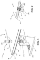
FIG. 1 illustrates a perspective view of a sandwich panel of a thermal protection system attached to base structure, including an exploded view of a fastener and bracket used to attach the sandwich panel to the base structure, according to an aspect of the present disclosure. -
FIG. 2 illustrates a partial cross-sectional view of the sandwich panel and fastener ofFIG. 1 , including a pre-integrated soft goods seal positioned in a gap of the sandwich panel, according to an aspect of the present disclosure. -
FIGS. 3A and 3B show perspective views of a sandwich panel with insulation components positioned between a sandwich panel and a base structure, including a view of a soft goods seal positioned out of a gap inFIG. 3A and a view of the soft goods seal positioned in the gap inFIG. 3B , according to an aspect of the present disclosure. -
FIG. 4A shows a cup washer fastener locking mechanism positioned to surround an orifice in the sandwich panel ofFIG. 1 , according to an aspect of the present disclosure. -
FIG. 4B shows the fastener ofFIG. 1 positioned flush on the outermost surface of the thermal protection system with the cup washer locking mechanism engaged, according to an aspect of the present disclosure. -
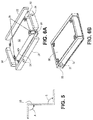
FIG. 5 shows a schematic sideview of a standoff bracket, according to an aspect of the present disclosure. -
FIGS. 6A and 6B show a plurality of insulation components positioned around standoff brackets between each sandwich panel and a base structure, according to an aspect of the present disclosure. -
FIGS. 7A to 7F illustrate a method of assembling a stand-off panel thermal protection system, according to an aspect of the present disclosure. -
FIG. 8 illustrates a perspective view of a flight vehicle, according to an aspect of the present disclosure. - It should be noted that some details of the figures have been simplified and are drawn to facilitate understanding rather than to maintain strict structural accuracy, detail, and scale.
- Reference will now be made in detail to the present teachings, examples of which are illustrated in the accompanying drawings. In the drawings, like reference numerals have been used throughout to designate identical elements. In the following description, reference is made to the accompanying drawings that form a part thereof, and in which is shown by way of illustration specific examples of practicing the present teachings. The following description is, therefore, merely exemplary.
- The present invention comprises a parasitic, stand-off panel thermal protection system ("TPS") 1, views of which are shown in
FIGS. 1 to 7 of the present disclosure. Referring toFIG. 1 , the TPS 1 comprises a plurality ofsandwich panels 10. Eachsandwich panel 10 comprises a first ceramicmatrix composite facesheet 12 and a second ceramicmatrix composite facesheet 14. A ceramicmatrix composite core 16 is positioned between the first ceramicmatrix composite facesheet 12 and the second ceramicmatrix composite facesheet 14. The ceramicmatrix composite core 16 shown inFIG. 1 has an exposed perimeter 16a. The first ceramicmatrix composite facesheet 12 and the second ceramicmatrix composite facesheet 14 extend past the perimeter 16a to form agap 18 between the first ceramicmatrix composite facesheet 12 and the second ceramicmatrix composite facesheet 14.Gap 18 extends around the entire edge of thesandwich panel 10. A soft goods seal 20 is positioned in the gap as shown inFIGS. 2 ,3A and 3B . Theseal 20 extends around the entire perimeter of thesandwich panel 10. - The first ceramic
matrix composite facesheet 12 and the second ceramicmatrix composite facesheet 14 can comprise any suitable oxide ceramic matrix composite or non-oxide ceramic matrix composite material. Suitable oxide ceramic matrix composite or non-oxide ceramic matrix composite materials are well known in the art. In an embodiment, the materials are non-oxide matrix composite materials comprising silicon carbide fibers, carbon fibers or both, within a silicon carbide matrix. The ceramicmatrix composite core 16 also comprises any suitable oxide ceramic matrix composite or non-oxide ceramic matrix composite material. This can also be, for example, composite materials comprising silicon carbide fibers, carbon fibers or both, within a silicon carbide matrix. The ceramic matrix composite material for the facesheets and the core can be the same type of material (e.g., both oxide CMC or both non-oxide CMC) or a different type of material. - The
sandwich panel 10, including the facesheets and ceramic matrix composite core, can be in the form of a C/SiC (e.g., carbon fibers in a silicon carbide matrix) or SiC/SiC (e.g., silicon carbide fibers in a silicon carbide matrix) truss core panel. Such panels can provide increased structural efficiency and temperature capability compared to alternate stand-off panel designs. Examples of such panels are known in the art. - The soft goods seal 20 comprises at least one material preferably chosen from alumina, silica, carbon fibers or silicon carbide fibers woven into a desired seal structure. Suitable soft goods seals are generally well known in the art. Examples of such seals include a NEXTEL™ woven soft goods seal sock, which comprises a woven ceramic fabric filled with alumina fibrous batting insulation. The soft goods seal 20 is capable of withstanding high temperatures of, for example, 1315,56 °C (2400°F), while preventing or reducing plasma flow to areas beneath the seal. Soft goods seal 20 also has enough compliance to deform as the panels undergo thermal expansion. Soft goods seal 20 can be pre-integrated into the
gap 18 in any suitable manner prior to assembly of the thermal protection system. For example, the soft goods seal can be sewn into position in thegap 18, or held in position by compression fit. - The
sandwich panels 10 can be fastened to any desired base structure using a fastening system suitable for high temperature applications. Referring toFIGS. 1 and7E , a plurality offasteners 24 are positionable through a plurality oforifices 22 formed through the sandwich panel to couple thesandwich panel 10 to a plurality of stand-off brackets 26. The stand-off brackets 26 are positioned between eachsandwich panel 10 and abase structure 28 to which the TPS is to be attached. For example, the stand-off brackets 26 can be attached to thebase structure 28; and the plurality offasteners 24 can be positioned through the plurality oforifices 22 to couple eachsandwich panel 10 to the plurality ofbrackets 26. In this manner, the stand-off brackets 26 can be used to couple thesandwich panels 10 to abase structure 28 so that thesandwich panels 10 are spaced from the base structure by a desired distance, D. - Any
suitable fasteners 24 can be employed, one example of which includes abolt 24A,washer 24B,nut 24C andnut retainer 24D, as illustrated inFIG. 1 . Thenut retainer 24D functions to hold the nuts in place during assembly of the thermal protection system.Nut retainer 24D can be held in position in any suitable manner, such as by attachingnut retainer 24D to thestandoff bracket 26. The plurality offasteners 24 andstandoff brackets 26 can be made of any suitable high temperature materials capable of provide the desired structural support for maintaining thesandwich panels 10 in position on thebase structure 28. Suitable materials include ceramics, such as alumina, and high temperature metallic material. The ceramic fastener materials can be selected so as to be capable of withstanding extreme environments without the need for panel plugs or other features to protect the fasteners. For example, the materials can be capable of withstanding high temperatures experienced by a flight vehicle upon reentry into earth's atmosphere and/or at hypersonic speeds without significant degradation in properties or excessive thermal expansion. In one example, thefasteners standoff brackets 26 comprise a ceramic material, such as alumina, and thenut retainer 24D is made of a high temperature metal (as described below). One example of a ceramic material that can be used for thefasteners - As shown in
FIG. 2 , a reinforcing ceramic matrixcomposite insert 36 can be positioned to surround each of the plurality of orifices in thesandwich panel 10 so as to reinforce theorifice 22, react loads and/or distribute loads to thefacesheets sandwich panels 10 of the present disclosure. The reinforcing inserts provide the reinforcement described above, which allows thefasteners 24 to hold thesandwich panels 10 in position while providing for easy access to the fasteners and still allowing for a relatively smooth outer surface due to thefasteners 24 being positioned flush with the outer surface ofsandwich panel 10, as described below. The reinforcingceramic inserts 36 comprise, for example, ceramic fiber (e.g., silicon carbide fiber or carbon fiber) in the form of ceramic matrix composite ("CMC") material that can provide the desired reinforcing properties. In an example, theceramic insert 36 can be made of the same material as the ceramic matrix composite core, and can be co-cured, or laid up, in the panel core. By the term "laid up" is meant that during the process for producing composite parts, the insert can be fabricated as a part of the panel during the same fabrication process, as opposed to being mechanically installed at a separate time. In an example, theinsert 36 can be a two dimensional (2D) or three dimensional (3D) laminate. Theceramic insert 36 can have any suitable shape or size that will provide the desired reinforcement of theorifices 22. For example, theinsert 36 can have a cylindrical, or "puck", shape with a diameter ranging from about 2.5 to about 12.7 cm (1 to about 5 inches), such as about 5 to about 7.5 cm (2 to about 3 inches). The insert can be shaped to accept the fastener such that the fastener is flush on the outermost surface of the thermal protection system, as shown inFIG. 4B . - Referring to
FIG. 4A , a cupwasher locking mechanism 38 can be positioned to surround each of the plurality of orifices in the sandwich panel. The cup washer locking mechanism can includetabs 40 that fold into grooves on the head offastener 24A, as shown inFIG. 4B . This can prevent the fasteners from rotating and thereby becoming loose in theorifices 22. Such cup washer locking mechanisms are generally known in the art. - The
standoff brackets 26 can be designed to flex to accommodate thermal expansion of the panels while maintaining sufficient strength and stiffness to react the high loads experience during launch and in flight. Thestandoff brackets 26 can be positioned in any desired manner. However, orienting thestandoff brackets 26 similarly as shown inFIG. 1 , so that panel thermal expansion has a tendency to bend the brackets to reduce angles A and B, as shown inFIG. 5 , can reduce the possibility of interlaminar tension failure of the standoff brackets. - Referring to
FIGS. 6A and 6B , a plurality ofinsulation components standoff brackets 26 between eachsandwich panel 10 and thebase structure 28.Insulation components facesheet 12. The insulation components can absorb heat and reduce the temperature increase of thebase structure 28 caused by a thermal event, thereby providing desired thermal protection.
Any suitable insulating components that are resistant to water absorption and that can withstand high temperatures while providing the desired insulation properties can be employed. As an example, each of theinsulation components resistant bag 31 filled withinsulation material 33. The water resistant bag can comprise a metal foil, such as a superalloy capable of withstanding extreme temperatures. One example of such a metal material is INCONEL® foil, which is a superalloy comprising nickel, chromium, austenite and one or more other ingredients. The bags can have one ormore vents 34 to reduce and/or prevent pressurization. The insulatingmaterial 33 in the bags can be a relatively low density insulation, for example, a batting having a density of about 16.02 kg/m3 to about 160.02 kg/m3 such as about 48.05 kg/m3 to about 96.11 kg/m3. While five insulating components are illustrated inFIG. 6A , any suitable number of insulating components can be employed depending on the size and shape of both thesandwich panel 10 and of the insulating components themselves. - Referring to
FIGS. 7A to 7F , the present application is also directed to a method of assembling a stand-off panel thermal protection system. The method comprises attaching stand-off brackets 26 to abase structure 28, as shown inFIG. 7A . A plurality ofinsulation components off brackets 26, as shown inFIGS. 7B, 7C and 7D . Asandwich panel 10 is attached to the stand-off brackets 26 withfasteners 24, as shown inFIG. 7E , with the soft goods seal 20 positioned in thegap 18, as is described above and shown with respect toFIGS. 3A and 3B . Any of thesandwich panels 10 described herein can be employed in the method of the present disclosure. Thefasteners 24 can be tightened and then locked in place using the cupwasher locking mechanism 38, as described above. Once completed, the full thermal protection system comprises an array ofsandwich panels 10, as shown for example inFIG. 7F , attached to thebase structure 28 of, for example, a flight vehicle, so as to form an outer surface thereof. - Referring to
FIG. 8 , the present disclosure is also directed to aflight vehicle 50. The flight vehicle can comprise a vehicle body base structure and any of the stand-off panel thermal protection systems 1 of the present disclosure coupled to the base structure. The flight vehicle can be, for example, a rocket, an aircraft or a spacecraft, such as a reusable spacecraft. Thesandwich panels 10 and the plurality of insulation components positioned between eachsandwich panel 10 and the vehicle body base structure can protect the flight vehicle from extreme thermal events, such as may occur upon reentry into the earth's atmosphere or during hypersonic flight. - As can be understood from looking at
FIGS. 1 and8 , thesecond ceramic facesheet 14 of each sandwich panel 10 (shown inFIG. 1 ) provides a portion of outermost surface 52 (shown inFIG. 8 ) of the flight vehicle. The plurality offasteners 24 for eachsandwich panel 10 are externally accessible at theoutermost surface portion 52 on the flight vehicle, as shown inFIG. 4B . - The ability to install fasteners from the outermost surface of the panel can reduce installation time and/or replacement time and costs. Traditionally, fasteners that attach the TPS system to the vehicle structure have been concealed below the surface to avoid exposure to high temperatures. This requires an access feature, such as a plug or insert, in the panel that covers the fasteners, which can be complex to integrate into the system. An alternative approach involves providing access to fasteners between panels, which makes the integration of a robust sealing concept challenging. The TPS system of the present disclosure simplifies installation by providing fastener access from the outer surface, which can improve overall system reliability and/or reduce installation, maintenance, and repair costs. The use of
pre-installed seals 20, as discussed above, can further simplify installation, as theseals 20 are installed as pre-integrated components with the sandwich panels. This removes an additional installation step that has proven to be challenging in alternative designs. The panel design of the present disclosure can also eliminate or reduce the need for certain materials, e.g., waterproofing in some applications. - Notwithstanding that the numerical ranges and parameters setting forth the broad scope of the disclosure are approximations, the numerical values set forth in the specific examples are reported as precisely as possible. Any numerical value, however, inherently contains certain errors necessarily resulting from the standard deviation found in their respective testing measurements. Moreover, all ranges disclosed herein are to be understood to encompass any and all sub-ranges subsumed therein.
- Further, the disclosure comprises embodiments according to the following clauses:
- Clause 1 A stand-off panel thermal protection system, comprising: a sandwich panel comprising: a first ceramic matrix composite facesheet and a second ceramic matrix composite facesheet, a ceramic matrix composite core positioned between the first ceramic matrix composite facesheet and the second ceramic matrix composite facesheet, the ceramic matrix composite core having a perimeter, the first ceramic matrix composite facesheet and the second ceramic matrix composite facesheet extending past the perimeter to form a gap between the first ceramic matrix composite facesheet and the second ceramic matrix composite facesheet surrounding the ceramic matrix composite core, and a plurality of orifices formed through the sandwich panel; a soft goods seal positioned in the gap; a plurality of insulation components; a plurality of stand-off brackets; and a plurality of fasteners positionable through the plurality of orifices to couple the sandwich panel to the plurality of brackets.
- Clause 2. The system of Clause 1, wherein the first ceramic matrix composite facesheet and the second ceramic matrix composite facesheet comprise at least one material chosen from oxide ceramic matrix composites or non-oxide ceramic matrix composites.
- Clause 3. The system of Clause 1 or 2, wherein the ceramic matrix composite core is a truss core comprising at least one material chosen from oxide ceramic matrix composites or non-oxide ceramic matrix composites.
- Clause 4. The system of any of the clauses 1-3, wherein the soft goods seal comprises woven ceramic fabric and alumina fibrous batting insulation.
- Clause 5.The system of any of the clauses 1-4, wherein each of the plurality of standoff brackets comprise a ceramic matrix composite material or high temperature metallic material.
- Clause 6. The system of any of the clauses 1-5 wherein each of the plurality of fasteners comprise a ceramic material.
- Clause 7. The system of any one of Clauses 1-6, further comprising a reinforcing ceramic insert positioned to surround each of the plurality of orifices in the sandwich panel.
- Clause 8. The system of any of the clauses 1-7, further comprising a cup washer locking mechanism positioned to surround each of the plurality of orifices in the sandwich panel.
- Clause 9. A method of assembling a stand-off panel thermal protection system, the method comprising: attaching stand-off brackets to a base structure; positioning a plurality of insulation components between and around the stand-off brackets; attaching a sandwich panel to the stand-off brackets with ceramic fasteners, the sandwich panel comprising: a first ceramic matrix composite facesheet and a second ceramic matrix composite facesheet, a ceramic matrix composite core positioned between the first ceramic matrix composite facesheet and the second ceramic matrix composite facesheet, the ceramic matrix composite core having a perimeter, the first ceramic matrix composite facesheet and the second ceramic matrix composite facesheet extending past the perimeter to form a gap surrounding the ceramic matrix composite core between the first ceramic matrix composite facesheet and the second ceramic matrix composite facesheet, a plurality of orifices formed through the sandwich panel, and a soft goods seal positioned in the gap.
-
Clause 10. The method of Clause 9, wherein the sandwich panel comprises a cup washer locking mechanism positioned to surround each of the plurality of orifices in the sandwich panel, the method further comprising locking the fasteners in place with the cup washer. - Clause 11. The method of
Clause 9 or 10, wherein the base structure is an object chosen from one of a rocket, an aircraft, or a spacecraft. -
Clause 12. A flight vehicle, comprising: a base structure; and a stand-off panel thermal protection system, comprising: a plurality of sandwich panels, each sandwich panel comprising:a first ceramic matrix composite facesheet and a second ceramic matrix composite facesheet, a ceramic matrix composite core positioned between the first ceramic matrix composite facesheet and the second ceramic matrix composite facesheet, the ceramic matrix composite core having a perimeter, the first ceramic matrix composite facesheet and the second ceramic matrix composite facesheet extending past the perimeter to form a gap between the first ceramic matrix composite facesheet and the second ceramic matrix composite facesheet surrounding the ceramic matrix composite core, and a plurality of orifices formed through each sandwich panel; a soft goods seal positioned in the gap of each sandwich panel; a plurality of insulation components positioned between each sandwich panel and the base structure; a plurality of stand-off brackets positioned between each sandwich panel and the base structure, the stand-off brackets being attached to the base structure; and a plurality of fasteners positioned through the plurality of orifices to couple each sandwich panel to the plurality of brackets. - Clause 13. The flight vehicle of
Clause 12, wherein the second ceramic matrix composite facesheet of each sandwich panel provides an outermost surface portion of the flight vehicle, the plurality of fasteners for each sandwich panel being externally accessible at the outermost surface portions. -
Clause 14. The flight vehicle ofClause 12 or 13, wherein the brackets comprise a first angle and a second angle, the brackets being oriented so that if thermal expansion of the sandwich panels occur, the brackets bend so as to reduce the first angle and the second angle. - Clause 15. The flight vehicle of any of the clauses 12-14, wherein the first ceramic matrix composite facesheet and the second ceramic matrix composite facesheet comprise at least one material chosen from oxide ceramic matrix composites or non-oxide ceramic matrix composites.
-
Clause 16. The flight vehicle of any of the clauses 12-15, wherein the ceramic matrix composite core is a truss core comprising at least one material chosen from oxide ceramic matrix composites or non-oxide ceramic matrix composites. - Clause 17. The flight vehicle of of any of the clauses 12-16, wherein the soft goods seal comprises woven ceramic fabric and alumina fibrous batting insulation.
-
Clause 18. The flight vehicle of of any of the clauses 12-17, wherein each of the plurality of standoff brackets comprise a ceramic matrix composite material or high temperature metallic material. - Clause 19. The flight vehicle of of any of the clauses 12-18, wherein each of the plurality of fasteners comprise a ceramic material.
-
Clause 20. The flight vehicle of any one of Clauses 12-19, further comprising a reinforcing ceramic insert positioned to surround each of the plurality of orifices in the sandwich panel. - While the present teachings have been illustrated with respect to one or more implementations, alterations and/or modifications can be made to the illustrated examples without departing from the spirit and scope of the appended claims. In addition, while a particular feature of the present teachings may have been disclosed with respect to only one of several implementations, such feature may be combined with one or more other features of the other implementations as may be desired and advantageous for any given or particular function. Furthermore, to the extent that the terms "including," "includes," "having," "has," "with," or variants thereof are used in either the detailed description and the claims, such terms are intended to be inclusive in a manner similar to the term "comprising." Further, in the discussion and claims herein, the term "about" indicates that the value listed may be somewhat altered, as long as the alteration does not result in nonconformance of the process or structure to the intended purpose described herein. Finally, "exemplary" indicates the description is used as an example, rather than implying that it is an ideal.
- It will be appreciated that variants of the above-disclosed and other features and functions, or alternatives thereof, may be combined into many other different systems or applications. Various presently unforeseen or unanticipated alternatives, modifications, variations, or improvements therein may be subsequently made by those skilled in the art which are also intended to be encompasses by the following claims.
Claims (15)
- A stand-off panel thermal protection system 1, comprising:a sandwich panel (10) comprising:a first ceramic matrix composite facesheet (12) and a second ceramic matrix composite facesheet (14);a ceramic matrix composite core (16) positioned between the first ceramic matrix composite facesheet (12) and the second ceramic matrix composite facesheet (14), the ceramic matrix composite core (16) having a perimeter (16a), the first ceramic matrix composite facesheet (12) and the second ceramic matrix composite facesheet (14) extending past the perimeter (16a) to form a gap (18) between the first ceramic matrix composite facesheet (12) and the second ceramic matrix composite facesheet (14) surrounding the ceramic matrix composite core (16);a plurality of orifices (22) formed through the sandwich panel (10);a soft goods seal (20) positioned in the gap (18);a plurality of insulation components (30, 32);a plurality of stand-off brackets (26); anda plurality of fasteners (24) positionable through the plurality of orifices (22) to couple the sandwich panel (10) to the plurality of brackets (26).
- The system of claim 1, wherein the ceramic matrix composite core (16) is a truss core comprising at least one material chosen from oxide ceramic matrix composites or non-oxide ceramic matrix composites.
- The system of claim 1 or 2, wherein the soft goods seal (20) comprises woven ceramic fabric and alumina fibrous batting insulation.
- The system of any of the preceding claims wherein each of the plurality of standoff brackets (26) comprise a ceramic matrix composite material or high temperature metallic material.
- The system of any of the preceding claims wherein each of the plurality of fasteners (24) comprise a ceramic material.
- The system of any one of claims 1-5, further comprising a reinforcing ceramic insert (36) positioned to surround each of the plurality of orifices (22) in the sandwich panel (10).
- The system of any of the preceding claims further comprising a cup washer looking mechanism (38) positioned to surround each of the plurality of orifices (22) in the sandwich panel (10).
- A method of assembling a stand-off panel thermal protection system according to any of the preceding claims, the method comprising:attaching stand-off brackets (26) to a base structure (28);
positioning a plurality of insulation components (30, 32) between and around the stand-off brackets (26);attaching a sandwich panel (10) to the stand-off brackets (26) with ceramic fasteners (24), the sandwich panel comprising:a first ceramic matrix composite facesheet (12) and a second ceramic matrix composite facesheet (14);a ceramic matrix composite core (16) positioned between the first ceramic matrix composite facesheet (12) and the second ceramic matrix composite facesheet (14), the ceramic matrix composite core (16) having a perimeter (16a), the first ceramic matrix composite facesheet (12) and the second ceramic matrix composite facesheet (14) extending past the perimeter (16a) to form a gap (18) surrounding the ceramic matrix composite core (16) between the first ceramic matrix composite facesheet (12) and the second ceramic matrix composite facesheet (14);a plurality of orifices (22) formed through the sandwich panel (10), anda soft goods (20) seal positioned in the gap (18). - The method of claim 8, wherein the sandwich panel comprises a cup washer locking mechanism (38) positioned to surround each of the plurality of orifices (22) in the sandwich panel (10), the method further comprising locking the fasteners( 24A) in place with the cup washer.
- A flight vehicle, comprising:a base structure (28); anda stand-off panel thermal protection system (1), comprising:a plurality of sandwich panels (10), each sandwich panel comprising:a first ceramic matrix composite facesheet (12) and a second ceramic matrix composite facesheet (14);a ceramic matrix composite core (16) positioned between the first ceramic matrix composite facesheet (12) and the second ceramic matrix composite facesheet (14), the ceramic matrix composite core (16) having a perimeter (16a), the first ceramic matrix composite facesheet (12) and the second ceramic matrix composite facesheet (14) extending past the perimeter (16a) to form a gap (18) between the first ceramic matrix composite facesheet (12) and the second ceramic matrix composite facesheet (14) surrounding the ceramic matrix composite core (16);a plurality of orifices (22) formed through each sandwich panel (10);a soft goods seal (20) positioned in the gap (18) of each sandwich panel (10);a plurality of insulation components (30, 32) positioned between each sandwich panel (10) and the base structure (28);a plurality of stand-off brackets (26) positioned between each sandwich panel (10) and the base structure, the stand-off brackets (26) being attached to the base structure (28); anda plurality of fasteners (24) positioned through the plurality of orifices (22) to couple each sandwich panel (10) to the plurality of brackets (26), preferably wherein the second ceramic matrix composite facesheet (14) of each sandwich panel (10) provides an outermost surface portion of the flight vehicle, the plurality of fasteners (24) for each sandwich panel (10) being externally accessible at the outermost surface portions (52).
- The flight vehicle of claim 10, wherein the brackets (26) comprise a first angle and a second angle, the brackets (26) being oriented so that if thermal expansion of the sandwich panels (10) occur, the brackets (26) bend so as to reduce the first angle and the second angle.
- The flight vehicle of claim 10 or 11, wherein the ceramic matrix composite core (16) is a truss core comprising at least one material chosen from oxide ceramic matrix composites or non-oxide ceramic matrix composites.
- The flight vehicle of any of the claims 10-12 having one or more of the following:wherein the soft goods seal (20) comprises woven ceramic fabric and alumina fibrous batting insulation,wherein each of the plurality of fasteners (24) comprise a ceramic material,a reinforcing ceramic insert (36) positioned to surround each of the plurality of orifices (22) in the sandwich panel (10).
- A flight vehicle according to any of the preceding claims 10-13, comprising a stand-off panel thermal protection system according to any of the preceding claims 1-7.
- A stand-off panel thermal protection system obtainable according to the method of claims 8 or 9.
Priority Applications (1)
| Application Number | Priority Date | Filing Date | Title |
|---|---|---|---|
| EP17203721.0A EP3321191B1 (en) | 2015-06-12 | 2016-06-06 | Fastener and thermal protection system |
Applications Claiming Priority (1)
| Application Number | Priority Date | Filing Date | Title |
|---|---|---|---|
| US14/738,314 US9878809B2 (en) | 2015-06-12 | 2015-06-12 | Stand-off panel thermal protection system and method of fabricating the same |
Related Child Applications (2)
| Application Number | Title | Priority Date | Filing Date |
|---|---|---|---|
| EP17203721.0A Division-Into EP3321191B1 (en) | 2015-06-12 | 2016-06-06 | Fastener and thermal protection system |
| EP17203721.0A Division EP3321191B1 (en) | 2015-06-12 | 2016-06-06 | Fastener and thermal protection system |
Publications (2)
| Publication Number | Publication Date |
|---|---|
| EP3103727A1 true EP3103727A1 (en) | 2016-12-14 |
| EP3103727B1 EP3103727B1 (en) | 2018-04-18 |
Family
ID=56134111
Family Applications (2)
| Application Number | Title | Priority Date | Filing Date |
|---|---|---|---|
| EP17203721.0A Not-in-force EP3321191B1 (en) | 2015-06-12 | 2016-06-06 | Fastener and thermal protection system |
| EP16173036.1A Not-in-force EP3103727B1 (en) | 2015-06-12 | 2016-06-06 | Stand-off panel thermal protection system and method of fabricating the same |
Family Applications Before (1)
| Application Number | Title | Priority Date | Filing Date |
|---|---|---|---|
| EP17203721.0A Not-in-force EP3321191B1 (en) | 2015-06-12 | 2016-06-06 | Fastener and thermal protection system |
Country Status (5)
| Country | Link |
|---|---|
| US (2) | US9878809B2 (en) |
| EP (2) | EP3321191B1 (en) |
| JP (1) | JP6441851B2 (en) |
| CN (1) | CN106240092B (en) |
| RU (1) | RU2708266C2 (en) |
Cited By (2)
| Publication number | Priority date | Publication date | Assignee | Title |
|---|---|---|---|---|
| EP3159321A1 (en) * | 2015-10-21 | 2017-04-26 | The Boeing Company | Whisker reinforced high fracture toughness ceramic threaded fasteners |
| WO2026022194A1 (en) | 2024-07-26 | 2026-01-29 | Saint-Gobain Centre De Recherches Et D'etudes Europeen | Super-insulating and refractory sandwich panel |
Families Citing this family (7)
| Publication number | Priority date | Publication date | Assignee | Title |
|---|---|---|---|---|
| US10266248B2 (en) * | 2016-07-20 | 2019-04-23 | The Boeing Company | Leading edge systems and methods for aerospace vehicles |
| CN108058809B (en) * | 2017-12-27 | 2023-07-14 | 中国航天空气动力技术研究院 | A non-thermal short-circuit reusable non-ablative thermal protection structure and processing method |
| WO2019241221A1 (en) * | 2018-06-12 | 2019-12-19 | Blue Origin, Llc | Metal encapsulated ceramic tile thermal insulation, and associated systems and methods |
| CN110626011B (en) * | 2019-09-11 | 2023-09-26 | 巩义市泛锐熠辉复合材料有限公司 | A kind of thermal protection board |
| CN113800940B (en) * | 2021-09-22 | 2022-07-15 | 中国科学院金属研究所 | Biomimetic lightweight thermal insulation sandwich structure and preparation method thereof |
| FR3129658A1 (en) * | 2021-11-30 | 2023-06-02 | Airbus Operations | Heat shield comprising a main part and at least one secondary part, in particular for a part of an aircraft. |
| FR3139165B1 (en) * | 2022-08-23 | 2024-08-30 | Arianegroup Sas | Shock Absorbed Lashing Stud Separation Device |
Citations (3)
| Publication number | Priority date | Publication date | Assignee | Title |
|---|---|---|---|---|
| WO2003045684A1 (en) * | 2001-11-27 | 2003-06-05 | Composite Optics, Inc. | Method and system of thermal protection |
| US20040091736A1 (en) * | 2002-11-11 | 2004-05-13 | Dichiara Robert A. | Method for secondarily bonding a ceramic matrix composite layer to a flexible insulation blanket and an insulation blanket produced thereby |
| FR2945792A1 (en) * | 2009-05-19 | 2010-11-26 | Snecma Propulsion Solide | Thermal protection device for use in thermal protection system of atmospheric re-entry vehicle, has skirt extending to outer side from stiffening wall whose edges are aligned with edges to delimit drain space between internal face and skirt |
Family Cites Families (37)
| Publication number | Priority date | Publication date | Assignee | Title |
|---|---|---|---|---|
| US490553A (en) * | 1893-01-24 | Nut-lock | ||
| US2151919A (en) * | 1935-03-25 | 1939-03-28 | Illinois Tool Works | Locking device |
| US2154655A (en) * | 1937-04-10 | 1939-04-18 | William H Bahan | Eccentric connection for loom swords |
| US3648749A (en) * | 1970-02-05 | 1972-03-14 | Central Screw Co | Fastener assembly with locking capabilities |
| US3783922A (en) * | 1972-09-05 | 1974-01-08 | Eaton Corp | Blind mounting fastener |
| US4557444A (en) * | 1984-01-09 | 1985-12-10 | The United States Of America As Represented By The Administrator Of The National Aeronautics And Space Administration | Aerospace vehicle |
| US4543345A (en) * | 1984-02-09 | 1985-09-24 | The United States Of America As Represented By The Department Of Energy | Silicon carbide whisker reinforced ceramic composites and method for making same |
| US4906150A (en) * | 1985-07-17 | 1990-03-06 | Bennett Bruce A | Locking fastener |
| FR2586080B1 (en) | 1985-08-12 | 1987-11-27 | Centre Nat Etd Spatiales | THERMAL PROTECTION ELEMENT FOR A MACHINE SUBJECT TO IMPORTANT HEATING |
| FR2586246B1 (en) | 1985-08-19 | 1991-04-05 | Aerospatiale | SINTERED CERAMIC MATERIAL WITH REINFORCING FILAMENTS AND METHOD FOR MANUFACTURING SUCH MATERIAL |
| FR2610921B1 (en) | 1987-02-16 | 1991-10-04 | Aerospatiale | COMPOSITE CERAMIC MATERIAL WITH REINFORCEMENT FILAMENTS, AND METHOD FOR MANUFACTURING SUCH MATERIAL |
| DE3741733A1 (en) * | 1987-12-09 | 1989-06-29 | Messerschmitt Boelkow Blohm | HIGH TEMPERATURE HEAT PROTECTION SYSTEM |
| US4938644A (en) * | 1989-05-22 | 1990-07-03 | Eaton Corporation | Bolt and nut lock assembly |
| US4975014A (en) * | 1989-09-01 | 1990-12-04 | The Boeing Company | High temperature low thermal expansion fastener |
| US5279191A (en) * | 1990-10-10 | 1994-01-18 | Gte Valenite Corporation | Reinforced alumina ceramic-metal bodies |
| FR2692633B1 (en) * | 1992-06-17 | 1995-08-25 | Aerospatiale | HARDWARE IN COMPOSITE MATERIAL CONSISTING OF A CERAMIC MATRIX REINFORCED WITH REFRACTORY FIBERS. |
| JPH10226400A (en) * | 1997-02-18 | 1998-08-25 | Hitachi Ltd | Thermal protection material |
| US6027293A (en) * | 1999-01-15 | 2000-02-22 | Deere & Company | Nut retaining plate |
| US6136418A (en) * | 1999-03-01 | 2000-10-24 | Rotary Rocket Company | Rapidly removable thermal protection system for reusable launch vehicle |
| DE19929874C1 (en) * | 1999-06-29 | 2000-07-27 | Dornier Gmbh | Screw connection for fiber-reinforced ceramic materials is for use in space and air travel in high temperature ranges and comprises bolt, nut and concentric bush |
| US6293496B1 (en) * | 1999-08-06 | 2001-09-25 | The B. F. Goodrich Company | Strain compatible attachment for metallic thermal protection system for a space vehicle |
| USH1981H1 (en) * | 2000-05-18 | 2001-08-07 | The United States Of America As Represented By The United States Department Of Energy | Bearing stress-free locking device |
| US6595732B2 (en) * | 2000-11-03 | 2003-07-22 | Case Corporation | Retainer cage for fastener |
| US7037065B2 (en) * | 2002-03-20 | 2006-05-02 | Alstom Technology Ltd | Flange bolt for turbines |
| US20060137294A1 (en) * | 2004-01-13 | 2006-06-29 | Waits Jr Bobby L | Expanded fastener for a honeycomb structure and method of assembly |
| US8313056B2 (en) * | 2005-07-19 | 2012-11-20 | United Technologies Corporation | Engine heat exchanger with thermoelectric generation |
| US20090004425A1 (en) * | 2007-06-28 | 2009-01-01 | The Boeing Company | Ceramic Matrix Composite Structure having Fluted Core and Method for Making the Same |
| US7943227B2 (en) * | 2007-10-11 | 2011-05-17 | The Boeing Company | Ceramic heat shield |
| CN201163163Y (en) * | 2008-01-02 | 2008-12-10 | 蔡兆文 | Z-shaped side belt |
| JP2009274284A (en) * | 2008-05-13 | 2009-11-26 | Ube Ind Ltd | Heat-resistant sandwich panel comprising polyimide composite material and its method for manufacturing |
| US8291594B2 (en) * | 2008-08-01 | 2012-10-23 | The Boeing Company | Attachment system and method for thermal protection system |
| US9211960B2 (en) * | 2008-10-21 | 2015-12-15 | The Boeing Company | System and method for attaching thermal protection, insulation and secondary structures to sandwich structures |
| US8752350B2 (en) | 2009-01-12 | 2014-06-17 | The Boeing Company | Ceramic composite thermal protection system |
| US9079674B1 (en) * | 2009-09-18 | 2015-07-14 | Blue Origin, Llc | Composite structures for aerospace vehicles, and associated systems and methods |
| HK1137111A2 (en) * | 2010-02-10 | 2010-07-16 | 惠州市显龙建材有限公司 | Composite board for construction and decoration |
| US9447811B2 (en) * | 2011-06-28 | 2016-09-20 | Nicholas Strumbos | Fastener and retainer assembly |
| US10101099B2 (en) * | 2015-03-12 | 2018-10-16 | Airbus Defence And Space Netherlands B.V. | Radiator, as well as space vehicle structure comprising such radiator |
-
2015
- 2015-06-12 US US14/738,314 patent/US9878809B2/en not_active Expired - Fee Related
-
2016
- 2016-04-01 RU RU2016112339A patent/RU2708266C2/en active
- 2016-04-07 JP JP2016077106A patent/JP6441851B2/en not_active Expired - Fee Related
- 2016-05-19 CN CN201610333388.6A patent/CN106240092B/en not_active Expired - Fee Related
- 2016-06-06 EP EP17203721.0A patent/EP3321191B1/en not_active Not-in-force
- 2016-06-06 EP EP16173036.1A patent/EP3103727B1/en not_active Not-in-force
-
2017
- 2017-11-03 US US15/803,625 patent/US10913552B2/en not_active Expired - Fee Related
Patent Citations (3)
| Publication number | Priority date | Publication date | Assignee | Title |
|---|---|---|---|---|
| WO2003045684A1 (en) * | 2001-11-27 | 2003-06-05 | Composite Optics, Inc. | Method and system of thermal protection |
| US20040091736A1 (en) * | 2002-11-11 | 2004-05-13 | Dichiara Robert A. | Method for secondarily bonding a ceramic matrix composite layer to a flexible insulation blanket and an insulation blanket produced thereby |
| FR2945792A1 (en) * | 2009-05-19 | 2010-11-26 | Snecma Propulsion Solide | Thermal protection device for use in thermal protection system of atmospheric re-entry vehicle, has skirt extending to outer side from stiffening wall whose edges are aligned with edges to delimit drain space between internal face and skirt |
Cited By (4)
| Publication number | Priority date | Publication date | Assignee | Title |
|---|---|---|---|---|
| EP3159321A1 (en) * | 2015-10-21 | 2017-04-26 | The Boeing Company | Whisker reinforced high fracture toughness ceramic threaded fasteners |
| US11268560B2 (en) | 2015-10-21 | 2022-03-08 | The Boeing Company | Method of making whisker reinforced high fracture toughness ceramic threaded fasteners |
| WO2026022194A1 (en) | 2024-07-26 | 2026-01-29 | Saint-Gobain Centre De Recherches Et D'etudes Europeen | Super-insulating and refractory sandwich panel |
| FR3164944A1 (en) | 2024-07-26 | 2026-01-30 | Saint-Gobain Centre De Recherches Et D'etudes Europeen | SUPER INSULATING AND REFRACTORY SANDWICH PANEL |
Also Published As
| Publication number | Publication date |
|---|---|
| JP2017001659A (en) | 2017-01-05 |
| US20180057192A1 (en) | 2018-03-01 |
| CN106240092A (en) | 2016-12-21 |
| RU2708266C2 (en) | 2019-12-05 |
| US10913552B2 (en) | 2021-02-09 |
| EP3103727B1 (en) | 2018-04-18 |
| EP3321191B1 (en) | 2022-05-04 |
| RU2016112339A3 (en) | 2019-09-30 |
| RU2016112339A (en) | 2017-10-05 |
| CN106240092B (en) | 2019-02-01 |
| US9878809B2 (en) | 2018-01-30 |
| EP3321191A1 (en) | 2018-05-16 |
| US20160362199A1 (en) | 2016-12-15 |
| JP6441851B2 (en) | 2018-12-19 |
Similar Documents
| Publication | Publication Date | Title |
|---|---|---|
| EP3103727B1 (en) | Stand-off panel thermal protection system and method of fabricating the same | |
| JP5385308B2 (en) | Plate and ring CMC nozzle | |
| JP3431263B2 (en) | Insulation protection device for flying objects | |
| US8047550B2 (en) | Tile gap seal assembly and method | |
| EP3360803B1 (en) | Rigidized hybrid insulating non-oxide thermal protection system and method of producing a non-oxide ceramic composite for making the same | |
| EP1448369B1 (en) | Method and system of thermal protection | |
| US6419189B1 (en) | Hot ruddervator apparatus and method for an aerospacecraft | |
| WO1983003796A1 (en) | Heat insulating blanket | |
| EP0245644A2 (en) | Ceramic/ceramic shell tile thermal protection system and method thereof | |
| US6293496B1 (en) | Strain compatible attachment for metallic thermal protection system for a space vehicle | |
| JP2017001659A5 (en) | ||
| EP2311732B1 (en) | Blanket assembly | |
| US20140332604A1 (en) | Device for Fastening a Hollow Part | |
| US6505794B2 (en) | Large thermal protection system panel | |
| US20220282672A1 (en) | Fire protection structure | |
| US8017213B2 (en) | Temperature tolerant hooks for hook and loop attachment | |
| Antonenko et al. | High Temperature Insulations on the X-38 Re-Entry Vehicle | |
| Pichon et al. | Integrated thermal protection systems and heat resistant structures | |
| JPH0453832B2 (en) | ||
| Fischer | CT v 252c_grid. qxd 8/22/2015 6: 22 PM Page 265 | |
| JPH05221398A (en) | Space shuttle |
Legal Events
| Date | Code | Title | Description |
|---|---|---|---|
| PUAI | Public reference made under article 153(3) epc to a published international application that has entered the european phase |
Free format text: ORIGINAL CODE: 0009012 |
|
| STAA | Information on the status of an ep patent application or granted ep patent |
Free format text: STATUS: REQUEST FOR EXAMINATION WAS MADE |
|
| 17P | Request for examination filed |
Effective date: 20160606 |
|
| AK | Designated contracting states |
Kind code of ref document: A1 Designated state(s): AL AT BE BG CH CY CZ DE DK EE ES FI FR GB GR HR HU IE IS IT LI LT LU LV MC MK MT NL NO PL PT RO RS SE SI SK SM TR |
|
| AX | Request for extension of the european patent |
Extension state: BA ME |
|
| RIC1 | Information provided on ipc code assigned before grant |
Ipc: B64G 1/58 20060101AFI20170426BHEP Ipc: B64G 1/14 20060101ALN20170426BHEP |
|
| GRAP | Despatch of communication of intention to grant a patent |
Free format text: ORIGINAL CODE: EPIDOSNIGR1 |
|
| STAA | Information on the status of an ep patent application or granted ep patent |
Free format text: STATUS: GRANT OF PATENT IS INTENDED |
|
| INTG | Intention to grant announced |
Effective date: 20170607 |
|
| GRAJ | Information related to disapproval of communication of intention to grant by the applicant or resumption of examination proceedings by the epo deleted |
Free format text: ORIGINAL CODE: EPIDOSDIGR1 |
|
| STAA | Information on the status of an ep patent application or granted ep patent |
Free format text: STATUS: REQUEST FOR EXAMINATION WAS MADE |
|
| GRAP | Despatch of communication of intention to grant a patent |
Free format text: ORIGINAL CODE: EPIDOSNIGR1 |
|
| STAA | Information on the status of an ep patent application or granted ep patent |
Free format text: STATUS: GRANT OF PATENT IS INTENDED |
|
| INTC | Intention to grant announced (deleted) | ||
| RIC1 | Information provided on ipc code assigned before grant |
Ipc: B64G 1/14 20060101ALN20170712BHEP Ipc: B64G 1/58 20060101AFI20170712BHEP |
|
| INTG | Intention to grant announced |
Effective date: 20170726 |
|
| GRAJ | Information related to disapproval of communication of intention to grant by the applicant or resumption of examination proceedings by the epo deleted |
Free format text: ORIGINAL CODE: EPIDOSDIGR1 |
|
| STAA | Information on the status of an ep patent application or granted ep patent |
Free format text: STATUS: REQUEST FOR EXAMINATION WAS MADE |
|
| GRAP | Despatch of communication of intention to grant a patent |
Free format text: ORIGINAL CODE: EPIDOSNIGR1 |
|
| STAA | Information on the status of an ep patent application or granted ep patent |
Free format text: STATUS: GRANT OF PATENT IS INTENDED |
|
| INTC | Intention to grant announced (deleted) | ||
| RIC1 | Information provided on ipc code assigned before grant |
Ipc: B64G 1/14 20060101ALN20171030BHEP Ipc: B64G 1/58 20060101AFI20171030BHEP |
|
| INTG | Intention to grant announced |
Effective date: 20171116 |
|
| GRAS | Grant fee paid |
Free format text: ORIGINAL CODE: EPIDOSNIGR3 |
|
| GRAA | (expected) grant |
Free format text: ORIGINAL CODE: 0009210 |
|
| STAA | Information on the status of an ep patent application or granted ep patent |
Free format text: STATUS: THE PATENT HAS BEEN GRANTED |
|
| AK | Designated contracting states |
Kind code of ref document: B1 Designated state(s): AL AT BE BG CH CY CZ DE DK EE ES FI FR GB GR HR HU IE IS IT LI LT LU LV MC MK MT NL NO PL PT RO RS SE SI SK SM TR |
|
| REG | Reference to a national code |
Ref country code: GB Ref legal event code: FG4D |
|
| REG | Reference to a national code |
Ref country code: CH Ref legal event code: EP |
|
| REG | Reference to a national code |
Ref country code: AT Ref legal event code: REF Ref document number: 990173 Country of ref document: AT Kind code of ref document: T Effective date: 20180515 |
|
| REG | Reference to a national code |
Ref country code: IE Ref legal event code: FG4D |
|
| REG | Reference to a national code |
Ref country code: DE Ref legal event code: R096 Ref document number: 602016002514 Country of ref document: DE |
|
| REG | Reference to a national code |
Ref country code: FR Ref legal event code: PLFP Year of fee payment: 3 |
|
| REG | Reference to a national code |
Ref country code: NL Ref legal event code: MP Effective date: 20180418 |
|
| REG | Reference to a national code |
Ref country code: LT Ref legal event code: MG4D |
|
| PG25 | Lapsed in a contracting state [announced via postgrant information from national office to epo] |
Ref country code: NL Free format text: LAPSE BECAUSE OF FAILURE TO SUBMIT A TRANSLATION OF THE DESCRIPTION OR TO PAY THE FEE WITHIN THE PRESCRIBED TIME-LIMIT Effective date: 20180418 |
|
| PG25 | Lapsed in a contracting state [announced via postgrant information from national office to epo] |
Ref country code: LT Free format text: LAPSE BECAUSE OF FAILURE TO SUBMIT A TRANSLATION OF THE DESCRIPTION OR TO PAY THE FEE WITHIN THE PRESCRIBED TIME-LIMIT Effective date: 20180418 Ref country code: FI Free format text: LAPSE BECAUSE OF FAILURE TO SUBMIT A TRANSLATION OF THE DESCRIPTION OR TO PAY THE FEE WITHIN THE PRESCRIBED TIME-LIMIT Effective date: 20180418 Ref country code: NO Free format text: LAPSE BECAUSE OF FAILURE TO SUBMIT A TRANSLATION OF THE DESCRIPTION OR TO PAY THE FEE WITHIN THE PRESCRIBED TIME-LIMIT Effective date: 20180718 Ref country code: SE Free format text: LAPSE BECAUSE OF FAILURE TO SUBMIT A TRANSLATION OF THE DESCRIPTION OR TO PAY THE FEE WITHIN THE PRESCRIBED TIME-LIMIT Effective date: 20180418 Ref country code: PL Free format text: LAPSE BECAUSE OF FAILURE TO SUBMIT A TRANSLATION OF THE DESCRIPTION OR TO PAY THE FEE WITHIN THE PRESCRIBED TIME-LIMIT Effective date: 20180418 Ref country code: ES Free format text: LAPSE BECAUSE OF FAILURE TO SUBMIT A TRANSLATION OF THE DESCRIPTION OR TO PAY THE FEE WITHIN THE PRESCRIBED TIME-LIMIT Effective date: 20180418 Ref country code: AL Free format text: LAPSE BECAUSE OF FAILURE TO SUBMIT A TRANSLATION OF THE DESCRIPTION OR TO PAY THE FEE WITHIN THE PRESCRIBED TIME-LIMIT Effective date: 20180418 Ref country code: BG Free format text: LAPSE BECAUSE OF FAILURE TO SUBMIT A TRANSLATION OF THE DESCRIPTION OR TO PAY THE FEE WITHIN THE PRESCRIBED TIME-LIMIT Effective date: 20180718 |
|
| PG25 | Lapsed in a contracting state [announced via postgrant information from national office to epo] |
Ref country code: RS Free format text: LAPSE BECAUSE OF FAILURE TO SUBMIT A TRANSLATION OF THE DESCRIPTION OR TO PAY THE FEE WITHIN THE PRESCRIBED TIME-LIMIT Effective date: 20180418 Ref country code: GR Free format text: LAPSE BECAUSE OF FAILURE TO SUBMIT A TRANSLATION OF THE DESCRIPTION OR TO PAY THE FEE WITHIN THE PRESCRIBED TIME-LIMIT Effective date: 20180719 Ref country code: LV Free format text: LAPSE BECAUSE OF FAILURE TO SUBMIT A TRANSLATION OF THE DESCRIPTION OR TO PAY THE FEE WITHIN THE PRESCRIBED TIME-LIMIT Effective date: 20180418 Ref country code: HR Free format text: LAPSE BECAUSE OF FAILURE TO SUBMIT A TRANSLATION OF THE DESCRIPTION OR TO PAY THE FEE WITHIN THE PRESCRIBED TIME-LIMIT Effective date: 20180418 |
|
| REG | Reference to a national code |
Ref country code: AT Ref legal event code: MK05 Ref document number: 990173 Country of ref document: AT Kind code of ref document: T Effective date: 20180418 |
|
| PG25 | Lapsed in a contracting state [announced via postgrant information from national office to epo] |
Ref country code: PT Free format text: LAPSE BECAUSE OF FAILURE TO SUBMIT A TRANSLATION OF THE DESCRIPTION OR TO PAY THE FEE WITHIN THE PRESCRIBED TIME-LIMIT Effective date: 20180820 |
|
| REG | Reference to a national code |
Ref country code: DE Ref legal event code: R097 Ref document number: 602016002514 Country of ref document: DE |
|
| PG25 | Lapsed in a contracting state [announced via postgrant information from national office to epo] |
Ref country code: AT Free format text: LAPSE BECAUSE OF FAILURE TO SUBMIT A TRANSLATION OF THE DESCRIPTION OR TO PAY THE FEE WITHIN THE PRESCRIBED TIME-LIMIT Effective date: 20180418 Ref country code: DK Free format text: LAPSE BECAUSE OF FAILURE TO SUBMIT A TRANSLATION OF THE DESCRIPTION OR TO PAY THE FEE WITHIN THE PRESCRIBED TIME-LIMIT Effective date: 20180418 Ref country code: EE Free format text: LAPSE BECAUSE OF FAILURE TO SUBMIT A TRANSLATION OF THE DESCRIPTION OR TO PAY THE FEE WITHIN THE PRESCRIBED TIME-LIMIT Effective date: 20180418 Ref country code: RO Free format text: LAPSE BECAUSE OF FAILURE TO SUBMIT A TRANSLATION OF THE DESCRIPTION OR TO PAY THE FEE WITHIN THE PRESCRIBED TIME-LIMIT Effective date: 20180418 Ref country code: SK Free format text: LAPSE BECAUSE OF FAILURE TO SUBMIT A TRANSLATION OF THE DESCRIPTION OR TO PAY THE FEE WITHIN THE PRESCRIBED TIME-LIMIT Effective date: 20180418 Ref country code: CZ Free format text: LAPSE BECAUSE OF FAILURE TO SUBMIT A TRANSLATION OF THE DESCRIPTION OR TO PAY THE FEE WITHIN THE PRESCRIBED TIME-LIMIT Effective date: 20180418 |
|
| PLBE | No opposition filed within time limit |
Free format text: ORIGINAL CODE: 0009261 |
|
| STAA | Information on the status of an ep patent application or granted ep patent |
Free format text: STATUS: NO OPPOSITION FILED WITHIN TIME LIMIT |
|
| PG25 | Lapsed in a contracting state [announced via postgrant information from national office to epo] |
Ref country code: SM Free format text: LAPSE BECAUSE OF FAILURE TO SUBMIT A TRANSLATION OF THE DESCRIPTION OR TO PAY THE FEE WITHIN THE PRESCRIBED TIME-LIMIT Effective date: 20180418 |
|
| REG | Reference to a national code |
Ref country code: BE Ref legal event code: MM Effective date: 20180630 |
|
| REG | Reference to a national code |
Ref country code: IE Ref legal event code: MM4A |
|
| 26N | No opposition filed |
Effective date: 20190121 |
|
| PG25 | Lapsed in a contracting state [announced via postgrant information from national office to epo] |
Ref country code: LU Free format text: LAPSE BECAUSE OF NON-PAYMENT OF DUE FEES Effective date: 20180606 Ref country code: MC Free format text: LAPSE BECAUSE OF FAILURE TO SUBMIT A TRANSLATION OF THE DESCRIPTION OR TO PAY THE FEE WITHIN THE PRESCRIBED TIME-LIMIT Effective date: 20180418 |
|
| PG25 | Lapsed in a contracting state [announced via postgrant information from national office to epo] |
Ref country code: IE Free format text: LAPSE BECAUSE OF NON-PAYMENT OF DUE FEES Effective date: 20180606 |
|
| PG25 | Lapsed in a contracting state [announced via postgrant information from national office to epo] |
Ref country code: BE Free format text: LAPSE BECAUSE OF NON-PAYMENT OF DUE FEES Effective date: 20180630 Ref country code: SI Free format text: LAPSE BECAUSE OF FAILURE TO SUBMIT A TRANSLATION OF THE DESCRIPTION OR TO PAY THE FEE WITHIN THE PRESCRIBED TIME-LIMIT Effective date: 20180418 |
|
| PG25 | Lapsed in a contracting state [announced via postgrant information from national office to epo] |
Ref country code: MT Free format text: LAPSE BECAUSE OF NON-PAYMENT OF DUE FEES Effective date: 20180606 |
|
| REG | Reference to a national code |
Ref country code: CH Ref legal event code: PL |
|
| PG25 | Lapsed in a contracting state [announced via postgrant information from national office to epo] |
Ref country code: TR Free format text: LAPSE BECAUSE OF FAILURE TO SUBMIT A TRANSLATION OF THE DESCRIPTION OR TO PAY THE FEE WITHIN THE PRESCRIBED TIME-LIMIT Effective date: 20180418 |
|
| PG25 | Lapsed in a contracting state [announced via postgrant information from national office to epo] |
Ref country code: CH Free format text: LAPSE BECAUSE OF NON-PAYMENT OF DUE FEES Effective date: 20190630 Ref country code: LI Free format text: LAPSE BECAUSE OF NON-PAYMENT OF DUE FEES Effective date: 20190630 |
|
| PG25 | Lapsed in a contracting state [announced via postgrant information from national office to epo] |
Ref country code: CY Free format text: LAPSE BECAUSE OF FAILURE TO SUBMIT A TRANSLATION OF THE DESCRIPTION OR TO PAY THE FEE WITHIN THE PRESCRIBED TIME-LIMIT Effective date: 20180418 Ref country code: MK Free format text: LAPSE BECAUSE OF NON-PAYMENT OF DUE FEES Effective date: 20180418 Ref country code: HU Free format text: LAPSE BECAUSE OF FAILURE TO SUBMIT A TRANSLATION OF THE DESCRIPTION OR TO PAY THE FEE WITHIN THE PRESCRIBED TIME-LIMIT; INVALID AB INITIO Effective date: 20160606 |
|
| PG25 | Lapsed in a contracting state [announced via postgrant information from national office to epo] |
Ref country code: IS Free format text: LAPSE BECAUSE OF FAILURE TO SUBMIT A TRANSLATION OF THE DESCRIPTION OR TO PAY THE FEE WITHIN THE PRESCRIBED TIME-LIMIT Effective date: 20180818 |
|
| P01 | Opt-out of the competence of the unified patent court (upc) registered |
Effective date: 20230516 |
|
| PGFP | Annual fee paid to national office [announced via postgrant information from national office to epo] |
Ref country code: FR Payment date: 20230626 Year of fee payment: 8 Ref country code: DE Payment date: 20230626 Year of fee payment: 8 |
|
| PGFP | Annual fee paid to national office [announced via postgrant information from national office to epo] |
Ref country code: IT Payment date: 20230620 Year of fee payment: 8 Ref country code: GB Payment date: 20230627 Year of fee payment: 8 |
|
| REG | Reference to a national code |
Ref country code: DE Ref legal event code: R119 Ref document number: 602016002514 Country of ref document: DE |
|
| GBPC | Gb: european patent ceased through non-payment of renewal fee |
Effective date: 20240606 |
|
| PG25 | Lapsed in a contracting state [announced via postgrant information from national office to epo] |
Ref country code: DE Free format text: LAPSE BECAUSE OF NON-PAYMENT OF DUE FEES Effective date: 20250101 |
|
| PG25 | Lapsed in a contracting state [announced via postgrant information from national office to epo] |
Ref country code: FR Free format text: LAPSE BECAUSE OF NON-PAYMENT OF DUE FEES Effective date: 20240630 |
|
| PG25 | Lapsed in a contracting state [announced via postgrant information from national office to epo] |
Ref country code: IT Free format text: LAPSE BECAUSE OF NON-PAYMENT OF DUE FEES Effective date: 20240606 Ref country code: GB Free format text: LAPSE BECAUSE OF NON-PAYMENT OF DUE FEES Effective date: 20240606 |