EP3103701A1 - Electrostatic capacity sensor and grip detection device - Google Patents
Electrostatic capacity sensor and grip detection device Download PDFInfo
- Publication number
- EP3103701A1 EP3103701A1 EP15746668.1A EP15746668A EP3103701A1 EP 3103701 A1 EP3103701 A1 EP 3103701A1 EP 15746668 A EP15746668 A EP 15746668A EP 3103701 A1 EP3103701 A1 EP 3103701A1
- Authority
- EP
- European Patent Office
- Prior art keywords
- electrode units
- electrostatic capacity
- commonly connected
- rim
- electrode
- Prior art date
- Legal status (The legal status is an assumption and is not a legal conclusion. Google has not performed a legal analysis and makes no representation as to the accuracy of the status listed.)
- Granted
Links
- 238000001514 detection method Methods 0.000 title claims abstract description 183
- 239000000758 substrate Substances 0.000 claims description 32
- 238000010586 diagram Methods 0.000 description 10
- 239000000463 material Substances 0.000 description 5
- 239000010949 copper Substances 0.000 description 4
- 239000011162 core material Substances 0.000 description 4
- 230000002265 prevention Effects 0.000 description 4
- RYGMFSIKBFXOCR-UHFFFAOYSA-N Copper Chemical compound [Cu] RYGMFSIKBFXOCR-UHFFFAOYSA-N 0.000 description 2
- BQCADISMDOOEFD-UHFFFAOYSA-N Silver Chemical compound [Ag] BQCADISMDOOEFD-UHFFFAOYSA-N 0.000 description 2
- 239000003575 carbonaceous material Substances 0.000 description 2
- 229910052802 copper Inorganic materials 0.000 description 2
- 230000003247 decreasing effect Effects 0.000 description 2
- 230000000694 effects Effects 0.000 description 2
- 229910052709 silver Inorganic materials 0.000 description 2
- 239000004332 silver Substances 0.000 description 2
- 239000007787 solid Substances 0.000 description 2
- 239000004642 Polyimide Substances 0.000 description 1
- 239000000853 adhesive Substances 0.000 description 1
- 239000002390 adhesive tape Substances 0.000 description 1
- 230000015572 biosynthetic process Effects 0.000 description 1
- 239000011248 coating agent Substances 0.000 description 1
- 238000000576 coating method Methods 0.000 description 1
- 239000004020 conductor Substances 0.000 description 1
- 239000010985 leather Substances 0.000 description 1
- 229920001721 polyimide Polymers 0.000 description 1
Images



Classifications
-
- B—PERFORMING OPERATIONS; TRANSPORTING
- B62—LAND VEHICLES FOR TRAVELLING OTHERWISE THAN ON RAILS
- B62D—MOTOR VEHICLES; TRAILERS
- B62D1/00—Steering controls, i.e. means for initiating a change of direction of the vehicle
- B62D1/02—Steering controls, i.e. means for initiating a change of direction of the vehicle vehicle-mounted
- B62D1/04—Hand wheels
- B62D1/046—Adaptations on rotatable parts of the steering wheel for accommodation of switches
-
- B—PERFORMING OPERATIONS; TRANSPORTING
- B62—LAND VEHICLES FOR TRAVELLING OTHERWISE THAN ON RAILS
- B62D—MOTOR VEHICLES; TRAILERS
- B62D1/00—Steering controls, i.e. means for initiating a change of direction of the vehicle
- B62D1/02—Steering controls, i.e. means for initiating a change of direction of the vehicle vehicle-mounted
- B62D1/04—Hand wheels
- B62D1/06—Rims, e.g. with heating means; Rim covers
-
- G—PHYSICS
- G01—MEASURING; TESTING
- G01D—MEASURING NOT SPECIALLY ADAPTED FOR A SPECIFIC VARIABLE; ARRANGEMENTS FOR MEASURING TWO OR MORE VARIABLES NOT COVERED IN A SINGLE OTHER SUBCLASS; TARIFF METERING APPARATUS; MEASURING OR TESTING NOT OTHERWISE PROVIDED FOR
- G01D5/00—Mechanical means for transferring the output of a sensing member; Means for converting the output of a sensing member to another variable where the form or nature of the sensing member does not constrain the means for converting; Transducers not specially adapted for a specific variable
- G01D5/12—Mechanical means for transferring the output of a sensing member; Means for converting the output of a sensing member to another variable where the form or nature of the sensing member does not constrain the means for converting; Transducers not specially adapted for a specific variable using electric or magnetic means
- G01D5/14—Mechanical means for transferring the output of a sensing member; Means for converting the output of a sensing member to another variable where the form or nature of the sensing member does not constrain the means for converting; Transducers not specially adapted for a specific variable using electric or magnetic means influencing the magnitude of a current or voltage
- G01D5/24—Mechanical means for transferring the output of a sensing member; Means for converting the output of a sensing member to another variable where the form or nature of the sensing member does not constrain the means for converting; Transducers not specially adapted for a specific variable using electric or magnetic means influencing the magnitude of a current or voltage by varying capacitance
-
- G—PHYSICS
- G01—MEASURING; TESTING
- G01R—MEASURING ELECTRIC VARIABLES; MEASURING MAGNETIC VARIABLES
- G01R27/00—Arrangements for measuring resistance, reactance, impedance, or electric characteristics derived therefrom
- G01R27/02—Measuring real or complex resistance, reactance, impedance, or other two-pole characteristics derived therefrom, e.g. time constant
- G01R27/26—Measuring inductance or capacitance; Measuring quality factor, e.g. by using the resonance method; Measuring loss factor; Measuring dielectric constants ; Measuring impedance or related variables
- G01R27/2605—Measuring capacitance
Definitions
- This invention relates to an electrostatic capacity sensor mounted on a steering wheel of an automobile and to a grip detection device employing the electrostatic capacity sensor.
- a grip detection device that has an electrostatic capacity type sensor mounted on a steering wheel of an automobile and detects gripping of the steering wheel by a driver based on proximity detection of a human body by the electrostatic capacity type sensor, is known (Patent Document 1 and Patent Document 2).
- the present invention was made in view of the above-described problems, and has an object of providing an electrostatic capacity sensor and grip detection device that achieve simplification of structure by reducing the number of wirings and achieve prevention of a lowering of grip detection performance of the steering wheel.
- An electrostatic capacity sensor is an electrostatic capacity sensor mounted on a rim of a steering wheel, includes: a flexible substrate having an insulating property; and a plurality of electrode units comprising an electrostatic capacity detection electrode of elongated shape provided on said flexible substrate, and is characterized in that a plurality of said electrode units are configured so as to be mounted on said rim so as to extend along a direction in which said rim extends, and are configured so as to be provided in parallel along a circumferential direction of said rim having the direction in which said rim extends as its axial center, and in a plurality of said electrode units, at least two electrode units are commonly connected, and at least one electrode unit not commonly connected to the commonly connected two electrode units is disposed between the commonly connected two electrode units.
- a direction in which the rim extends refers to a direction following an outer form shape of the rim, and in the case of an annular shaped rim, for example, refers to a direction following an annular shape.
- a circumferential direction of the rim having the direction in which the rim extends as its axial center refers to a direction following an outer circumference of a rim cross section when the rim is sectioned in a plane perpendicularly crossing the direction in which the rim extends, and in the description below, is sometimes called a circumferential direction of the rim.
- a plurality of electrode units comprising an electrostatic capacity detection electrode of elongated shape are mounted on the rim so as to extend along a direction in which the rim extends, and are configured so as to be provided in parallel along a circumferential direction of the rim, hence a sensor structure is simple.
- at least two electrode units are commonly connected, and at least one electrode unit not commonly connected to the commonly connected two electrode units is disposed between the commonly connected two electrode units, hence each of the electrode units is provided in parallel such that electrode units not commonly connected to each other are disposed in vicinity, and the number of wirings extending from the plurality of electrode units to a detection circuit can be reduced without lowering grip detection performance.
- the plurality of electrode units may be configured such that adjacent electrode units are not commonly connected each other.
- the plurality of electrode units may be formed on a common flexible substrate.
- the flexible substrate may be divided into a plurality of flexible substrate pieces, and commonly connected electrode units may be formed on an identical flexible substrate piece, and an electrode unit not commonly connected to the commonly connected electrode units may be formed on a different flexible substrate piece.
- a grip detection device is a grip detection device, comprising: a steering wheel; an electrostatic capacity sensor mounted on a rim of said steering wheel: and a determination unit that determines whether a driver has gripped the steering wheel or not based on proximity detection of a human body by said electrostatic capacity sensor, the grip detection device being characterized in that the electrostatic capacity sensor includes a plurality of electrode units comprising an electrostatic capacity detection electrode of elongated shape, a plurality of said electrode units extend along a direction in which said rim extends, and are provided in parallel in a circumferential direction of said rim having the direction in which said rim extends as its axial center, in a plurality of said electrode units, at least two electrode units are commonly connected, and at least one electrode unit not commonly connected to the commonly connected two electrode units is disposed between the commonly connected two electrode units, and said determination unit determines that the driver has gripped the steering wheel when proximity of the human body has been detected by each of at least two electrode units not commonly connected to each other
- the sensor structure can be simplified, and the number of wirings extending from the plurality of electrode units to a detection circuit can be reduced without lowering grip detection performance.
- a determination unit determines that a driver has gripped the steering wheel when proximity of a human body has been detected by each of at least two electrode units not commonly connected to each other, hence a gripping misdetection due to inadvertent contact of the driver can be avoided.
- the plurality of electrode units provided in parallel along a circumferential direction of the rim are configured such that at least one electrode unit not commonly connected to commonly connected two electrode units is disposed between the commonly connected two electrode units, and such that electrode units not commonly connected to each other are disposed in vicinity, hence prevention of a lowering of grip detection performance can be achieved.
- the plurality of electrode units may be divided into at least two groups, and electrode units belonging to an identical group may be commonly connected each other, and the determination unit may be configured to determine that the driver has gripped the steering wheel when proximity of the human body has been detected by each of one electrode unit and an electrode unit belonging to a different group from this one electrode unit.
- the plurality of electrode units may be divided into at least three groups, and electrode units belonging to an identical group may be commonly connected each other, and the determination unit may be configured to determine that the driver has gripped the steering wheel when proximity of the human body has been detected by each of at least one electrode unit of all of different groups.
- the plurality of electrode units provided in parallel along a circumferential direction of the rim may be disposed such that adjacent electrode units belong to different groups each other.
- the present invention makes it possible to achieve simplification of structure by reducing the number or wirings and to achieve prevention of a lowering of grip detection performance of the steering wheel.
- Electrostatic capacity sensors and grip detection devices according to embodiments of the present invention will be described below with reference to the drawings.
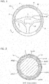
- Fig. 1 is a schematic view of an arrangement example to a steering wheel 1 of an electrostatic capacity sensor 2 according to the first embodiment, and of a grip detection device 10 employing said electrostatic capacity sensor 2.
- Fig. 1 is a front view of the steering wheel 1 attached to a vehicle body as seen from a seat side, and in the present embodiment, three electrostatic capacity sensors 2 are mounted on a rim 11 of the steering wheel 1.
- the grip detection device 10 is a steering wheel with a grip detection function, configured so as to detect gripping of the steering wheel by a driver, based on proximity detection of a human body by the electrostatic capacity sensor 2 mounted on the rim 11 of the steering wheel 1.
- the steering wheel 1 includes: the rim 11 extending annularly; and a center unit 12 disposed at a center of its annulus, and the rim 11 and the center unit 12 are coupled via three spokes.
- the steering wheel 1 is attached in a freely rotatable manner to the vehicle body, but the description below is assumed to describe up-down and right-left directions of the steering wheel 1 (rim 11) with reference to the steering wheel I in a steering state during direct forward motion of the vehicle (state shown in Fig. 1 ).
- an inner circumferential side of the annulus of the annular rim 11 is sometimes called a rim inner circumferential side
- an outer circumferential side of the annulus of the annular rim 11 is sometimes called a rim outer circumferential side.
- the electrostatic capacity sensor 2 is mounted in each of three regions of a right region, an upper region, and a left region of the annular rim 11 of the steering wheel 1.
- the electrostatic capacity sensor 2 includes a plurality of electrode units comprising an electrostatic capacity detection electrode 22 of elongated shape, and the plurality of electrode units (each of the electrostatic capacity detection electrodes 22) extending along a direction in which the rim 11 extends are provided in parallel along a circumferential direction of the rim 11. Moreover, each of the electrode units (electrostatic capacity detection electrodes 22) is configured so as to detect proximity of the human body.
- the grip detection device 10 is a steering wheel with a grip detection function, and comprises: the steering wheel 1; the electrostatic capacity sensor 2 mounted on the rim 11 of the steering wheel 1; and a determination unit 3 that determines whether the driver has gripped the steering wheel or not based on proximity detection of the human body by the electrostatic capacity sensor 2. Moreover, the plurality of electrode units (electrostatic capacity detection electrodes 22) configuring the electrostatic capacity sensor 2 are connected to the determination unit 3 provided within the center unit 12, via a contact wiring 23.
- the right, upper, and left three regions of the annular rim 11 are each mounted with the electrostatic capacity sensor 2, but there may be one electrostatic capacity sensor 2 mounted over these three regions. Moreover, the electrostatic capacity sensor 2 may be mounted over the entire rim including a lower region.
- the determination unit 3 has been provided within the center unit 12 of the steering wheel 1, but may be provided in a place other than the center unit 12, or may be provided in another place separated from the steering wheel 1.
- Fig. 2 is a cross-sectional view taken along the line A-A' of the rim 11 of the steering wheel 1 shown in Fig. 1 .
- the electrostatic capacity sensor 2 including six electrode units 2a-2f (electrostatic capacity detection electrodes 22) is mounted in a periphery of a core material 111 of substantially circular cross section configuring a central frame, on the rim 11 of the steering wheel 1. Moreover, its outer circumference is covered by a steering skin 113 configured from the likes of a leather material, via a cushioning material 112. Moreover, the six electrode units 2a-2f (electrostatic capacity detection electrodes 22) of the electrostatic capacity sensor 2 mounted on the rim 11 are provided in parallel separated at certain intervals (60° intervals) along the circumferential direction of the rim 11.
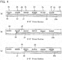
- Fig. 3 is a plan view of the electrostatic capacity sensor 2 according to the first embodiment before steering wheel mounting; and Figs. 4(a), (b), and (c) are respectively a cross-sectional view taken along the line B-B' shown in Fig. 3 looking in the direction of the arrows, a cross-sectional view taken along the line C-C' shown in Fig. 3 looking in the direction of the arrows, and a cross-sectional view taken along the line D-D' shown in Fig. 3 looking in the direction of the arrows.
- the electrostatic capacity sensor 2 includes: a flexible substrate 21 having an insulating property; and the electrostatic capacity detection electrode 22 formed on this flexible substrate 21.
- the flexible substrate 21 can employ a film which is thin and has flexibility, of the likes of polyimide or PET, for example.
- the electrostatic capacity detection electrodes 22 on the flexible substrate 21 are formed by, for example, solid coating a carbon material, or forming the carbon material in a mesh state, on a solid state wiring of silver (Ag) or copper (Cu), a mesh state wiring of silver (Ag) or copper (Cu), or a border wiring due to these conductive materials, and are each formed in an elongated shape.
- the electrostatic capacity sensor 2 includes the electrode units 2a-2f comprising six elongated shaped electrostatic capacity detection electrodes 22 formed on one flexible substrate 21, and these electrode units 2a-2f (electrostatic capacity detection electrodes 22) are provided in parallel along a direction crossing a longitudinal direction of the electrode units. Moreover, when the electrostatic capacity sensor 2 is mounted on the rim 11 of the steering wheel 1, the six elongated shaped electrode units 2a-2f (electrostatic capacity detection electrodes 22) are configured so as to each extend along the direction in which the rim 11 extends, and so as to be provided in parallel along the circumferential direction of the rim 11.
- each of the electrostatic capacity detection electrodes 22 configuring the six electrode units 2a-2f each of the electrostatic capacity detection electrodes 22 configuring the electrode units 2c, 2f disposed on the rim outer circumferential side and the rim inner circumferential side are formed in an elongated shape extending substantially in a straight line, and each of the electrostatic capacity detection electrodes 22 configuring the electrode units 2a, 2b, 2d, 2e disposed between those are formed in an arc shape matching a curvature of the rim 11.
- a radius of curvature of an arc shaped portion should be determined in view of the likes of flexibility and elasticity of the electrode units 2a-2f including the flexible substrate 21.
- Each of the electrode units 2a-2f of the electrostatic capacity sensor 2 are connected to the determination unit 3 via the contact wiring 23.
- the contact wiring 23 includes three wiring layers 23a-23c formed on the flexible substrate 21, and these wiring layers 23a-23c are formed extending in a direction crossing a longitudinal direction of the six electrode units 2a-2f (electrostatic capacity detection electrodes 22).
- each of the wiring layers 23a-23c is formed in a lower layer than each of the electrode units 2a-2f in a state of being insulated from each of the electrode units 2a-2f, at intersection portions with each of the electrode units 2a-2f.
- the electrode units 2a-2f (electrostatic capacity detection electrodes 22) and the wiring layers 23a-23c formed on the flexible substrate 21 are each covered and protected, and moreover, insulated from each other, by an insulating layer 25 of the likes of a resist.
- the wiring layer 23a formed in a lower layer than each of the electrode units 2a-2f is connected to the two electrode units 2a, 2d (electrostatic capacity detection electrodes 22) via a through wiring 24, and commonly connects these two electrode units 2a, 2d.
- the wiring layer 23b is connected to the two electrode units 2b, 2e (electrostatic capacity detection electrodes 22) via a through wiring 24, and commonly connects these two electrode units 2b, 2e.
- the wiring layer 23c is connected to the two electrode units 2c, 2f (electrostatic capacity detection electrodes 22) via a through wiring 24, and commonly connects these two electrode units 2c, 2f.
- the number of wirings of the contact wiring 23 (the number of wiring layers 23a-23c) extending from the electrostatic capacity sensor 2 to the determination unit 3 is reduced (halved) compared to the number of electrodes (the number of electrode units 2a-2f) of the electrostatic capacity sensor 2.
- the six electrode units 2a-2f configuring the electrostatic capacity sensor 2 are arranged one-dimensionally, and the electrode units 2b, 2c not commonly connected to the two electrode units [2a, 2d] commonly connected by the wiring layer 23a, are disposed between these commonly connected two electrodes. Moreover, the electrode units 2c, 2d not commonly connected to the two electrode units [2b, 2e] commonly connected by the wiring layer 23b, are disposed between these commonly connected two electrodes; and the electrode units 2d, 2e not commonly connected to the two electrode units [2c, 2f] commonly connected by the wiring layer 23c, are disposed between these commonly connected two electrodes.
- the electrostatic capacity sensor 2 mounted on the rim 11 has the six electrode units 2a-2f provided in parallel at certain intervals (60° intervals) along the circumferential direction of the rim 11, and commonly connected two electrode units [2a, 2d], [2b, 2e], [2c, 2f] are respectively disposed at facing positions (180° intervals) each other.
- the six electrode units 2a-2f provided in parallel along the circumferential direction of the rim 11 have the electrode units not commonly connected to commonly connected two electrode units respectively disposed between each of (between the two) commonly connected electrodes.
- Fig. 5 is a block diagram of the grip detection device 10 employing the electrostatic capacity sensor 2 of the present embodiment, and shows an electrical configuration of the electrostatic capacity sensor 2 and the determination unit 3.
- the grip detection device 10 comprises: the electrostatic capacity sensor 2 mounted on the rim 11 of the steering wheel 1; and the determination unit 3 that detects gripping of the steering wheel by the driver based on proximity detection of the human body by each of the electrode units 2a-2f of the electrostatic capacity sensor 2, and three wirings extend from the electrostatic capacity sensor 2 to the determination unit 3.
- the six electrode units 2a-2f configuring the electrostatic capacity sensor 2 are provided in parallel at substantially equal intervals (substantially 60° intervals) along the circumferential direction of the rim 11. Moreover, they are divided into three groups (first through third groups) such that one group is configured by electrode units disposed in facing positions each other, and electrode units belonging to an identical group [2a, 2d], [2b, 2e], [2c, 2f] are commonly connected each other. Moreover, adjacent electrode units (for example, 2f, 2a, 2b) are not commonly connected to each other, and respectively belong to different groups each other.
- the determination unit 3 is configured comprising: first through third C-V converting circuits 31a-31c; first through third detection circuits 32a-32c; and an arithmetic circuit 33.
- the commonly connected two electrode units [2a, 2d] are wired to the first detection circuit 32a via the first C-V converting circuit 31 a; the commonly connected two electrode units [2b, 2e] are wired to the second detection circuit 32b via the second C-V converting circuit 31 b; and the commonly connected two electrode units [2c, 2f] are wired to the third detection circuit 32c via the third C-V converting circuit 31 c.
- the first C-V converting circuit 31a connects the mutually commonly connected two electrode units [2a, 2d] as part of an integrating circuit, and by generating a voltage pulse whose duty ratio changes by an electrostatic capacity value detected by the electrode units 2a, 2d, changes the electrostatic capacity value into a voltage pulse.
- the second C-V converting circuit 31b connects the commonly connected two electrode units [2a, 2d] as part of an integrating circuit
- the third C-V converting circuit 31c connects the electrode units belonging to the third group [2c, 2f] as part of an integrating circuit, and by generating voltage pulses whose duty ratios change by electrostatic capacity values detected by the connected electrode units, change the electrostatic capacity values into voltage pulses.
- the first through third detection circuits 32a-32c DC-convert the voltage pulse outputted from the first through third C-V converting circuits 31a-31c to compare with a certain threshold value, thereby detecting the electrostatic capacity value. Moreover, on the basis of the detected electrostatic capacity value, they detect proximity of the human body in the electrode units [2a, 2d], [2b, 2e], [2c, 2f] connected to each of the detection circuits 32a-32c, and, when proximity of the human body has been detected, make output to the arithmetic circuit 33 active.
- the arithmetic circuit 33 is configured such that when only any one of the first through third detection circuits 32a-32c has become active, the driver is determined to have contacted the steering wheel, and when outputs of two or all of the first through third detection circuits 32a-32c have become active, the driver is determined to have gripped the steering wheel, distinguishes inadvertent contact and gripping of the steering wheel by the driver, and prevents a gripping misdetection.
- the arithmetic circuit 33 may be configured such that when outputs of one or two of the first through third detection circuits 32a-32c have become active, the driver is determined to have contacted the steering wheel, and when outputs of all of the first through third detection circuits 32a-32c have become active, the driver is determined to have gripped the steering wheel.
- an angle range for distinguishing gripping can be set large. That is, even if, for example, a limp arm, or the like, contacts the steering wheel and proximity of the human body is detected by adjacent two electrode units (for example, electrode units 2a, 2b), the arithmetic circuit 33 does not determine gripping, and when the driver bends their finger to grip the rim 11 and proximity of the human body has detected by three electrode units (for example, electrode units 2a, 2b, 2c), the arithmetic circuit 33 determines gripping. As a result, a gripping misdetection when an arm or the like has inadvertently contacted can also be prevented.
- the electrostatic capacity sensor 2 has a one-dimensional arrangement structure in which six electrode units 2a-2f of elongated shape are provided in parallel along a direction crossing their longitudinal directions, and has a simple sensor structure.
- the six electrode units 2a-2f have been provided in parallel along the circumferential direction of the rim, such that two electrode units [2a, 2d], [2b, 2e], [2c, 2f] are commonly connected each other and the contact wiring 23 (three wiring layers 23a-23c) is wired from the electrostatic capacity sensor 2 to the determination unit 3, and such that an electrode unit not commonly connected to commonly connected two electrode units is disposed between the commonly connected two electrode units, hence even if the number of wirings is reduced (halved), electrode units not commonly connected mutually to each other are disposed adjacently, and prevention of a lowering of grip detection performance can be achieved.
- the grip detection device 10 according to the first embodiment employs the above-described electrostatic capacity sensor 2 according to the first embodiment, hence simplification of sensor structure and reduction of the number of wirings can be achieved without lowering grip detection performance.
- the determination unit 3 is configured such that when proximity of the human body is detected by at least two electrode units not commonly connected to each other and at least two of the first through third detection circuits 32a-32c have become active, the driver is determined to have gripped the steering wheel. As a result, a gripping misdetection due to inadvertent contact by the driver can be prevented.
- the six electrode units 2a-2f provided in parallel at substantially equal intervals (substantially 60° intervals) along the circumferential direction of the rim 11 are each disposed such that adjacent electrode units belong to different groups each other and are thereby not commonly connected to each other, hence if proximity of the human body is detected by adjacent any two electrode units (any two electrode units disposed at substantially 60° intervals), at least two of the first through third detection circuits 32a-32c become active, and the determination unit 3 can determine that the driver has gripped the steering wheel.
- Fig. 6 is an exploded plan view of the electrostatic capacity sensor 2' according to the second embodiment before steering wheel mounting; and Fig. 7 is a cross-sectional view of the electrostatic capacity sensor 2' according to the second embodiment taken along the line E-E' of Fig. 6(b) and looking in the direction of the arrows.
- the electrostatic capacity sensor 2' of the second embodiment is configured such that the flexible substrate 21 is divided into three flexible substrate pieces 21 a, 21b, 21 c, and commonly connected electrode units (electrostatic capacity detection electrodes 22) of an identical group are formed for each of the flexible substrate pieces 21a-21c.
- the two electrode units 2a, 2d are formed on the flexible substrate piece 21a, and the wiring layer 23a commonly connecting these is formed as a wiring pattern of an identical layer.
- the two electrode units 2b, 2e are formed on the flexible substrate piece 21 b, and the wiring layer 23b commonly connecting these is formed as a wiring pattern of an identical layer.
- the two electrode units 2c, 2f are formed on the flexible substrate piece 21c, and the wiring layer 23c commonly connecting these is formed as a wiring pattern of an identical layer.
- the electrostatic capacity sensor 2' of the second embodiment can be formed by overlaying these three flexible substrate pieces 21a-21c, sequentially, from a lower layer, such that the respective electrode units 2a-2f are provided in parallel at fixed intervals.
- Fig. 7 is a cross-sectional view of the electrostatic capacity sensor 2' according to the second embodiment formed overlaying the three flexible substrate pieces 21 a-21 c, cutting along the line E-E' of Fig. 6(b) and looking in the direction of the arrows.
- the electrostatic capacity sensor 2' has the wiring layers 23a-23c and the two electrode units (electrostatic capacity detection electrodes 22) commonly connected by these wiring layers 23a-23c formed as a wiring pattern of an identical layer, hence does not require the through wiring 24 for connecting the wiring layer and the electrode unit like the electrostatic capacity sensor 2 according to the first embodiment. Therefore, a formation step of the wiring pattern can be simplified.
- a characteristic configuration of the grip detection device of the present embodiment is being configured such that the electrostatic capacity sensor 2 mounted on the rim 11 of the steering wheel 1 includes a plurality of electrode units comprising an electrostatic capacity detection electrode of elongated shape, the plurality of electrode units extend along the direction in which the rim extends and are provided in parallel along the circumferential direction of the rim, and, in the plurality of electrode units, at least two electrode units are commonly connected, and at least one electrode unit not commonly connected to commonly connected two electrode units is disposed between the commonly connected two electrode units.
- a characteristic configuration of the grip detection device of the present embodiment is being configured such that the determination unit that detects gripping of the steering wheel by the driver based on proximity detection of the human body by the electrostatic capacity sensor 2 determines that the driver has gripped the steering wheel when proximity of the human body has been detected by at least two electrode units not commonly connected to each other.
- the number of electrode units configuring the electrostatic capacity sensor the number of commonly connected electrode units, an arrangement interval of each of the electrode units, and an arrangement interval of the commonly connected electrode units can be appropriately changed.
- the electrostatic capacity sensor 2 including six electrode units 2a-2f (electrostatic capacity detection electrodes 22) was mounted on the rim 11, and the six electrode units 2a-2f (electrostatic capacity detection electrodes 22) were commonly connected in pairs, but the number of electrode units (electrostatic capacity detection electrodes 22) or the number of commonly connected electrode units (electrostatic capacity detection electrodes 22) can be appropriately changed according to what kind of range is set for an angle range to distinguish gripping.
- the plurality of electrode units are provided in parallel at substantially equal intervals along the circumferential direction of the rim 11 and commonly connected electrode units are also disposed at substantially equal intervals, but the arrangement interval of the plurality of electrode units or the arrangement interval of the commonly connected electrode units can be appropriately changed according to grip detection performance required at each position in the circumferential direction of the rim.
- the electrostatic capacity sensor 2 includes nine electrode units 2a-2i (electrostatic capacity detection electrodes 22), and three wirings extend from the electrostatic capacity sensor 2 to the determination unit 3.
- the nine electrode units 2a-2i are provided in parallel at substantially equal intervals (substantially 40° intervals) along the circumferential direction of the rim 11, and in those, three electrode units [2a, 2d, 2g], [2b, 2d, 2h], [2c, 2f, 2i] disposed at substantially 120° intervals are commonly connected each other as an identical group.
- the driver when only any one of the first through third detection circuits 32a-32c has become active, the driver is determined to have contacted the steering wheel (rim 11), and when two or all of the first through third detection circuits 32a-32c have become active, the driver is determined to have gripped the steering wheel (rim 11), whereby a gripping misdetection due to inadvertent contact of the steering wheel by the driver can be prevented, but the angle range when performing grip detection is smaller compared to in the first embodiment.
- the electrostatic capacity sensor 2 includes four electrode units 2a-2d (electrostatic capacity detection electrodes 22), and two wirings extend from the electrostatic capacity sensor 2 to the determination unit 3.
- the four electrode units 2a-2d are provided in parallel at substantially equal intervals (substantially 90° intervals) along the circumferential direction of the rim 11, and in those, two electrode units [2a, 2c], [2b, 2d] disposed at facing positions (substantially 180° intervals) are commonly connected each other as an identical group.
- the driver when either one of the first and second detection circuits 32a, 32b has become active, the driver is determined to have contacted the steering wheel (rim 11), and when both of the first and second detection circuits 32a, 32b have become active, the driver is determined to have gripped the steering wheel (rim 11), whereby a gripping misdetection due to inadvertent contact of the steering wheel by the driver can be prevented, but the angle range when performing grip detection is larger compared to in the first embodiment.
- the electrostatic capacity sensor 2 includes four electrode units 2a-2d (electrostatic capacity detection electrodes 22), and three wirings extend from the electrostatic capacity sensor 2 to the determination unit 3.
- the four electrode units 2a-2d are provided in parallel at unequal intervals along the circumferential direction of the rim 11. Moreover, in the four electrodes, two of the electrode units 2a, 2b (electrostatic capacity detection electrodes 22) disposed at positions closely adjacently to each other are commonly connected as an identical group, and are wired to the first detection circuit 32a. Moreover, in each of spaces (two spaces) between the commonly connected two electrode units 2a, 2b, one of the spaces has disposed therein each of the electrode unit 2c wired to the second detection circuit 32b and the electrode unit 2d wired to the third detection circuit 32c.
- the driver when only any one of the detection circuits 32a-32c has become active, the driver is determined to have contacted the steering wheel (rim 11), and when two or all of the detection circuits 32a-32c have become active, the driver is determined to have gripped the steering wheel (rim 11), whereby a gripping misdetection due to inadvertent contact of the steering wheel by the driver can be prevented.
- a grip detection device 10d according to a fourth modified example shown in Fig. 11 , the arrangement interval of the electrode units on the rim inner circumferential side is increased, whereby the number of electrode units is reduced.
- the electrostatic capacity sensor 2 including five electrode units 2a-2e (electrostatic capacity detection electrodes 22) is mounted on the rim 11, and two wirings (wiring layers) extend from the electrostatic capacity sensor 2 to the determination unit 3. Moreover, the five electrode units 2a-2e provided in parallel along the circumferential direction of the rim 11 are provided in parallel at unequal intervals such that the arrangement interval of the electrode units on the rim inner circumferential side increases.
- the three electrode units 2a, 2c, 2e disposed at substantially equal intervals (substantially 120° intervals) along the circumferential direction of the rim 11 are commonly connected as an identical group and wired to the first detection circuit 32a, the electrode unit 2b not commonly connected to the commonly connected electrode units [2a, 2c] is disposed at the center between these commonly connected electrode units [2a, 2c], and the electrode unit 2d not commonly connected to the commonly connected electrode units [2c, 2e] is disposed at the center between these commonly connected electrode units [2c, 2e]. Moreover, an electrode unit is not disposed between the electrode units [2e, 2a] on the rim inner circumferential side. Moreover, the two electrode units 2b, 2d disposed between each of the electrode units [2a, 2c], [2c, 2e] are commonly connected as an identical group to be wired to the second detection circuit 32b.
- the five electrode units 2a-2e are provided in parallel at substantially equal intervals (substantially 60° intervals) along the circumferential direction of the rim 11, and furthermore, the three electrode units 2a, 2c, 2e commonly connected to the first detection circuit 32a and the two electrode units 2b, 2d commonly connected to the second detection circuit 32b are disposed alternately.
- the determination unit 3 determines that the driver has contacted the steering wheel (rim 11). Moreover, when, in a region other than the rim inner circumferential side, proximity of the human body has been detected by adjacent two electrode units, and outputs of both of the first and second detection circuits 32a, 32b have become active, the driver is determined to have gripped the steering wheel (rim 11). As a result, a gripping misdetection due to inadvertent contact of the steering wheel by the driver can be prevented.
- a grip detection device 10e according to a fifth modified example shown in Fig. 12 similarly to in the fourth modified example, the arrangement interval of the electrode units on the rim inner circumferential side is increased, whereby the number of electrode units is reduced.
- the electrostatic capacity sensor 2 including five electrode units 2a-2e (electrostatic capacity detection electrodes 22) is mounted on the rim 11, and three wirings (wiring layers) extend from the electrostatic capacity sensor 2 to the determination unit 3. Moreover, the five electrode units 2a-2e provided in parallel along the circumferential direction of the rim 11 are disposed at unequal intervals such that the arrangement interval of the electrode units on the rim inner circumferential side increases.
- the three electrode units 2a, 2d, 2g disposed at substantially equal intervals (substantially 120° intervals) along the circumferential direction of the rim 11 are commonly connected as an identical group to be wired to the first detection circuit 32a, the electrode unit 2b not commonly connected to the commonly connected electrode units [2a, 2d] is disposed between these commonly connected electrode units [2a, 2d] to be wired to the second detection circuit 32b, and the electrode unit 2d not commonly connected to the commonly connected electrode units [2c, 2e] is disposed at the center between these commonly connected electrode units [2c, 2e] to be wired to the third detection circuit 32c.
- an electrode unit is not disposed between the electrode units [2e, 2a] on the rim inner circumferential side.
- the present modified example differs from the fourth modified example in that the electrode units 2b, 2d are not commonly connected and are respectively wired to the second or third detection circuits 32b, 32c.
- a grip detection device 10f in a grip detection device 10f according to a sixth modified example shown in Fig. 13 , similarly to in the fourth modified example, the arrangement interval of the electrode units on the rim inner circumferential side is increased, whereby the number of electrode units is reduced.
- the electrostatic capacity sensor 2 including seven electrode units 2a-2g (electrostatic capacity detection electrodes 22) is mounted on the rim 11, and three wirings (wiring layers) extend from the electrostatic capacity sensor 2 to the determination unit 3. Moreover, the seven electrode units 2a-2g provided in parallel along the circumferential direction of the rim 11 are disposed at unequal intervals such that the arrangement interval of the electrode units on the rim inner circumferential side increases.
- the three electrode units [2a, 2d, 2g] disposed at substantially equal intervals (substantially 120° intervals) along the circumferential direction of the rim 11 are commonly connected as an identical group to be wired to the first detection circuit 32a, the two electrode units 2b, 2c not commonly connected to the commonly connected electrode units [2a, 2d] are disposed at substantially equal intervals (substantially 40° intervals) between these commonly connected electrode units [2a, 2d], and the two electrode units 2e, 2f not commonly connected to the commonly connected electrode units [2d, 2g] are disposed at substantially equal intervals (substantially 40° intervals) between these commonly connected electrode units [2d, 2g].
- an electrode unit is not disposed between the electrode units [2g, 2a] on the rim inner circumferential side.
- the two electrode units 2b, 2e disposed at substantially 120° intervals are commonly connected to be wired to the second detection circuit 32b, and the two electrode units 2c, 2f disposed at substantially 120° intervals are commonly connected to be wired to the third detection circuit 32c.
- the present modified example differs from the first modified example in that an electrode unit is not disposed between the commonly connected two electrode units [2g, 2a] disposed on the rim inner circumferential side.
- a grip detection device 10g according to a seventh modified example shown in Fig. 14 similarly to in the fourth modified example, the arrangement interval of the electrode units on the rim inner circumferential side is increased, whereby the number of electrode units is reduced.
- the electrostatic capacity sensor 2 including seven electrode units 2a-2g (electrostatic capacity detection electrodes 22) is mounted on the rim 11, and three wirings (wiring layers) extend from the electrostatic capacity sensor 2 to the determination unit 3. Moreover, the seven electrode units 2a-2g provided in parallel along the circumferential direction of the rim 11 are disposed at unequal intervals such that the arrangement interval of the electrode units on the rim inner circumferential side increases.
- the three electrode units [2a, 2d, 2g] disposed at substantially equal intervals (substantially 120° intervals) along the circumferential direction of the rim 11 are commonly connected as an identical group to be wired to the first detection circuit 32a, the two electrode units 2b, 2c not commonly connected to the commonly connected electrode units [2a, 2d] are disposed at substantially equal intervals (substantially 40° intervals) between these commonly connected electrode units [2a, 2d], and the two electrode units 2e, 2f not commonly connected to the commonly connected electrode units [2d, 2g] are disposed at substantially equal intervals (substantially 40° intervals) between these commonly connected electrode units [2d, 2g].
- an electrode unit is not disposed between the electrode units [2g, 2a] on the rim inner circumferential side.
- the two electrode units 2b, 2c disposed between the commonly connected two electrode units [2a, 2d] are commonly connected to be wired to the second detection circuit 32b, and the two electrode units 2e, 2f disposed between the commonly connected two electrode units [2d, 2g] are commonly connected to be wired to the third detection circuit 32c.
- a common wiring of a plurality of the electrode units respectively disposed between two of the electrode units of the commonly connected three electrode units [2a, 2d, 2g], differs from the sixth modified example.
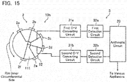
- a grip detection device 10h according to an eighth modified example shown in Fig. 15 similarly to in the fourth modified example, the arrangement interval of the electrode units on the rim inner circumferential side is increased, whereby the number of electrode units is reduced.
- the electrostatic capacity sensor 2 including six electrode units 2a-2f (electrostatic capacity detection electrodes 22) is mounted on the rim 11, and two wirings (wiring layers) extend from the electrostatic capacity sensor 2 to the determination unit 3. Moreover, the six electrode units 2a-2f provided in parallel along the circumferential direction of the rim 11 are disposed at unequal intervals such that the arrangement interval of the electrode units on the rim inner circumferential side increases.
- the six electrode units 2a-2f are provided in parallel along the circumferential direction of the rim so as to be at substantially 45° intervals.
- the three electrode units [2a, 2c, 2e] disposed at substantially 90° intervals along the circumferential direction of the rim 11 are commonly connected as an identical group to be wired to the first detection circuit 32a
- the three electrode units [2b, 2d, 2f] disposed at 90° intervals along the circumferential direction of the rim 11 are commonly connected as an identical group to be wired to the second detection circuit 32b.
- an electrode unit is not disposed between the two electrode units [2f, 2a] on the rim inner circumferential side.
Landscapes
- Engineering & Computer Science (AREA)
- Chemical & Material Sciences (AREA)
- Combustion & Propulsion (AREA)
- Transportation (AREA)
- Mechanical Engineering (AREA)
- Physics & Mathematics (AREA)
- General Physics & Mathematics (AREA)
- Steering Controls (AREA)
- Switches That Are Operated By Magnetic Or Electric Fields (AREA)
Abstract
Description
- This invention relates to an electrostatic capacity sensor mounted on a steering wheel of an automobile and to a grip detection device employing the electrostatic capacity sensor.
- A grip detection device that has an electrostatic capacity type sensor mounted on a steering wheel of an automobile and detects gripping of the steering wheel by a driver based on proximity detection of a human body by the electrostatic capacity type sensor, is known (
Patent Document 1 and Patent Document 2). - In the grip detection device described in
Patent Document 1, by mounting an electrostatic capacity touch panel on an annular shaped rim (gripping part) of the steering wheel, and determining that the driver is gripping the steering wheel when, of a large number of detection electrodes configuring the electrostatic capacity touch panel, the likes of a total area of the detection electrodes that have detected proximity of the human body is a certain value or more, a misdetection of gripping due to inadvertent contact of the driver is avoided. - In the grip detection device described in
Patent Document 2, by disposing one each of detection electrodes on an inner circumferential side and an outer circumferential side of an annular shaped rim (gripping part) of the steering wheel, and determining that the driver is gripping the steering wheel when each of these two detection electrodes has detected proximity of the human body, a misdetection of gripping due to inadvertent contact of the driver is avoided. -
- Patent Document 1:
-
JP 2013-75653 A - Patent Document 2:
-
JP 2014-19355 A - However, in the grip detection device disclosed in
Patent Document 1, an electrostatic capacity touch panel having a large number of two-dimensionally disposed detection electrodes is used, hence the number of wirings to a sensor IC also increases, and a structure is complicated. - On the other hand, in the grip detection device disclosed in
Patent Document 2, although there are only two detection electrodes disposed on the rim hence both the number of wirings to a sensor IC is few and a structure is simple, the driver, when gripping the steering wheel, has to consciously bring their finger close to each of two detection electrodes disposed at distant positions to grip the steering wheel, and grip detection performance is low. - The present invention was made in view of the above-described problems, and has an object of providing an electrostatic capacity sensor and grip detection device that achieve simplification of structure by reducing the number of wirings and achieve prevention of a lowering of grip detection performance of the steering wheel.
- An electrostatic capacity sensor according to the present invention is an electrostatic capacity sensor mounted on a rim of a steering wheel, includes: a flexible substrate having an insulating property; and a plurality of electrode units comprising an electrostatic capacity detection electrode of elongated shape provided on said flexible substrate, and is characterized in that a plurality of said electrode units are configured so as to be mounted on said rim so as to extend along a direction in which said rim extends, and are configured so as to be provided in parallel along a circumferential direction of said rim having the direction in which said rim extends as its axial center, and in a plurality of said electrode units, at least two electrode units are commonly connected, and at least one electrode unit not commonly connected to the commonly connected two electrode units is disposed between the commonly connected two electrode units.
- Note that in the present invention, "a direction in which the rim extends" refers to a direction following an outer form shape of the rim, and in the case of an annular shaped rim, for example, refers to a direction following an annular shape. In addition, "a circumferential direction of the rim having the direction in which the rim extends as its axial center" refers to a direction following an outer circumference of a rim cross section when the rim is sectioned in a plane perpendicularly crossing the direction in which the rim extends, and in the description below, is sometimes called a circumferential direction of the rim.
- Due to the electrostatic capacity sensor according to the present invention, a plurality of electrode units comprising an electrostatic capacity detection electrode of elongated shape are mounted on the rim so as to extend along a direction in which the rim extends, and are configured so as to be provided in parallel along a circumferential direction of the rim, hence a sensor structure is simple. Moreover, in the plurality of electrode units, at least two electrode units are commonly connected, and at least one electrode unit not commonly connected to the commonly connected two electrode units is disposed between the commonly connected two electrode units, hence each of the electrode units is provided in parallel such that electrode units not commonly connected to each other are disposed in vicinity, and the number of wirings extending from the plurality of electrode units to a detection circuit can be reduced without lowering grip detection performance.
- Note that in the above-described electrostatic capacity sensor, the plurality of electrode units may be configured such that adjacent electrode units are not commonly connected each other.
- Moreover, in the above-described electrostatic capacity sensor, the plurality of electrode units may be formed on a common flexible substrate.
- Moreover, in the above-described electrostatic capacity sensor, the flexible substrate may be divided into a plurality of flexible substrate pieces, and commonly connected electrode units may be formed on an identical flexible substrate piece, and an electrode unit not commonly connected to the commonly connected electrode units may be formed on a different flexible substrate piece.
- In addition, a grip detection device according to the present invention is a grip detection device, comprising: a steering wheel; an electrostatic capacity sensor mounted on a rim of said steering wheel: and a determination unit that determines whether a driver has gripped the steering wheel or not based on proximity detection of a human body by said electrostatic capacity sensor, the grip detection device being characterized in that the electrostatic capacity sensor includes a plurality of electrode units comprising an electrostatic capacity detection electrode of elongated shape, a plurality of said electrode units extend along a direction in which said rim extends, and are provided in parallel in a circumferential direction of said rim having the direction in which said rim extends as its axial center, in a plurality of said electrode units, at least two electrode units are commonly connected, and at least one electrode unit not commonly connected to the commonly connected two electrode units is disposed between the commonly connected two electrode units, and said determination unit determines that the driver has gripped the steering wheel when proximity of the human body has been detected by each of at least two electrode units not commonly connected to each other.
- Due to the grip detection device according to the present invention, as mentioned above, the sensor structure can be simplified, and the number of wirings extending from the plurality of electrode units to a detection circuit can be reduced without lowering grip detection performance.
- That is, in the grip detection device according to the present invention, a determination unit determines that a driver has gripped the steering wheel when proximity of a human body has been detected by each of at least two electrode units not commonly connected to each other, hence a gripping misdetection due to inadvertent contact of the driver can be avoided. Moreover, the plurality of electrode units provided in parallel along a circumferential direction of the rim are configured such that at least one electrode unit not commonly connected to commonly connected two electrode units is disposed between the commonly connected two electrode units, and such that electrode units not commonly connected to each other are disposed in vicinity, hence prevention of a lowering of grip detection performance can be achieved.
- Note that in the above-described grip detection device, the plurality of electrode units may be divided into at least two groups, and electrode units belonging to an identical group may be commonly connected each other, and the determination unit may be configured to determine that the driver has gripped the steering wheel when proximity of the human body has been detected by each of one electrode unit and an electrode unit belonging to a different group from this one electrode unit.
- Moreover, in the above-described grip detection device, the plurality of electrode units may be divided into at least three groups, and electrode units belonging to an identical group may be commonly connected each other, and the determination unit may be configured to determine that the driver has gripped the steering wheel when proximity of the human body has been detected by each of at least one electrode unit of all of different groups.
- Moreover, in the above-described grip detection device, the plurality of electrode units provided in parallel along a circumferential direction of the rim may be disposed such that adjacent electrode units belong to different groups each other.
- The present invention makes it possible to achieve simplification of structure by reducing the number or wirings and to achieve prevention of a lowering of grip detection performance of the steering wheel.
-
- [
Fig. 1] Fig. 1 is a schematic view of an arrangement example of an electrostatic capacity sensor and a grip detection device employing the same electrostatic capacity sensor, according to a first embodiment of the present invention. - [
Fig. 2] Fig. 2 is a cross-sectional view taken along the line A-A' inFig. 1 . - [
Fig. 3] Fig. 3 is a plan view of the same electrostatic capacity sensor. - [
Fig. 4] Fig. 4 is a cross-sectional view of the same electrostatic capacity sensor. - [
Fig. 5] Fig. 5 is a block diagram of the grip detection device employing the same electrostatic capacity sensor. - [
Fig. 6] Fig. 6 is a plan view of an electrostatic capacity sensor according to a second embodiment of the present invention. - [
Fig. 7] Fig. 7 is a cross-sectional of the same electrostatic capacity sensor. - [
Fig. 8] Fig. 8 is a block diagram of a grip detection device according to a first modified example. - [
Fig. 9] Fig. 9 is a block diagram of a grip detection device according to a second modified example. - [
Fig. 10] Fig. 10 is a block diagram of a grip detection device according to a third modified example. - [
Fig. 11] Fig. 11 is a block diagram of a grip detection device according to a fourth modified example. - [
Fig. 12] Fig. 12 is a block diagram of a grip detection device according to a fifth modified example. - [
Fig. 13] Fig. 13 is a block diagram of a grip detection device according to a sixth modified example. - [
Fig. 14] Fig. 14 is a block diagram of a grip detection device according to a seventh modified example. - [
Fig. 15] Fig. 15 is a block diagram of a grip detection device according to an eighth modified example. - Electrostatic capacity sensors and grip detection devices according to embodiments of the present invention will be described below with reference to the drawings.
- First, an electrostatic capacity sensor and a grip detection device employing the electrostatic capacity sensor, according to a first embodiment, will be described with reference to
Figs. 1 to 5 . -
Fig. 1 is a schematic view of an arrangement example to asteering wheel 1 of anelectrostatic capacity sensor 2 according to the first embodiment, and of agrip detection device 10 employing saidelectrostatic capacity sensor 2. -
Fig. 1 is a front view of thesteering wheel 1 attached to a vehicle body as seen from a seat side, and in the present embodiment, threeelectrostatic capacity sensors 2 are mounted on arim 11 of thesteering wheel 1. Moreover, thegrip detection device 10 according to the present embodiment is a steering wheel with a grip detection function, configured so as to detect gripping of the steering wheel by a driver, based on proximity detection of a human body by theelectrostatic capacity sensor 2 mounted on therim 11 of thesteering wheel 1. - The
steering wheel 1 includes: therim 11 extending annularly; and a center unit 12 disposed at a center of its annulus, and therim 11 and the center unit 12 are coupled via three spokes. - The
steering wheel 1 is attached in a freely rotatable manner to the vehicle body, but the description below is assumed to describe up-down and right-left directions of the steering wheel 1 (rim 11) with reference to the steering wheel I in a steering state during direct forward motion of the vehicle (state shown inFig. 1 ). Moreover, an inner circumferential side of the annulus of theannular rim 11 is sometimes called a rim inner circumferential side, and an outer circumferential side of the annulus of theannular rim 11 is sometimes called a rim outer circumferential side. - The
electrostatic capacity sensor 2 is mounted in each of three regions of a right region, an upper region, and a left region of theannular rim 11 of thesteering wheel 1. - The
electrostatic capacity sensor 2 according to the first embodiment includes a plurality of electrode units comprising an electrostaticcapacity detection electrode 22 of elongated shape, and the plurality of electrode units (each of the electrostatic capacity detection electrodes 22) extending along a direction in which therim 11 extends are provided in parallel along a circumferential direction of therim 11. Moreover, each of the electrode units (electrostatic capacity detection electrodes 22) is configured so as to detect proximity of the human body. - The
grip detection device 10 according to the first embodiment is a steering wheel with a grip detection function, and comprises: thesteering wheel 1; theelectrostatic capacity sensor 2 mounted on therim 11 of thesteering wheel 1; and adetermination unit 3 that determines whether the driver has gripped the steering wheel or not based on proximity detection of the human body by theelectrostatic capacity sensor 2. Moreover, the plurality of electrode units (electrostatic capacity detection electrodes 22) configuring theelectrostatic capacity sensor 2 are connected to thedetermination unit 3 provided within the center unit 12, via acontact wiring 23. - In the present embodiment, the right, upper, and left three regions of the
annular rim 11 are each mounted with theelectrostatic capacity sensor 2, but there may be oneelectrostatic capacity sensor 2 mounted over these three regions. Moreover, theelectrostatic capacity sensor 2 may be mounted over the entire rim including a lower region. - Moreover, the
determination unit 3 has been provided within the center unit 12 of thesteering wheel 1, but may be provided in a place other than the center unit 12, or may be provided in another place separated from thesteering wheel 1. -
Fig. 2 is a cross-sectional view taken along the line A-A' of therim 11 of thesteering wheel 1 shown inFig. 1 . - The
electrostatic capacity sensor 2 including sixelectrode units 2a-2f (electrostatic capacity detection electrodes 22) is mounted in a periphery of acore material 111 of substantially circular cross section configuring a central frame, on therim 11 of thesteering wheel 1. Moreover, its outer circumference is covered by a steeringskin 113 configured from the likes of a leather material, via acushioning material 112. Moreover, the sixelectrode units 2a-2f (electrostatic capacity detection electrodes 22) of theelectrostatic capacity sensor 2 mounted on therim 11 are provided in parallel separated at certain intervals (60° intervals) along the circumferential direction of therim 11. - Note that by an outer circumference of the
core material 111 mounted with theelectrostatic capacity sensor 2 being covered by the steeringskin 113 via thecushioning material 112, unevenness of anelectrostatic capacity sensor 2 surface can be reduced. Moreover, adhesion of each of layers of thecore material 111, theelectrostatic capacity sensor 2, thecushioning material 112, and thesteering skin 113 can be performed by a double-sided adhesive tape or an adhesive agent, for example. -
Fig. 3 is a plan view of theelectrostatic capacity sensor 2 according to the first embodiment before steering wheel mounting; andFigs. 4(a), (b), and (c) are respectively a cross-sectional view taken along the line B-B' shown inFig. 3 looking in the direction of the arrows, a cross-sectional view taken along the line C-C' shown inFig. 3 looking in the direction of the arrows, and a cross-sectional view taken along the line D-D' shown inFig. 3 looking in the direction of the arrows. - As shown in
Fig. 3 , theelectrostatic capacity sensor 2 includes: aflexible substrate 21 having an insulating property; and the electrostaticcapacity detection electrode 22 formed on thisflexible substrate 21. - The
flexible substrate 21 can employ a film which is thin and has flexibility, of the likes of polyimide or PET, for example. - Moreover, the electrostatic
capacity detection electrodes 22 on theflexible substrate 21 are formed by, for example, solid coating a carbon material, or forming the carbon material in a mesh state, on a solid state wiring of silver (Ag) or copper (Cu), a mesh state wiring of silver (Ag) or copper (Cu), or a border wiring due to these conductive materials, and are each formed in an elongated shape. - The
electrostatic capacity sensor 2 includes theelectrode units 2a-2f comprising six elongated shaped electrostaticcapacity detection electrodes 22 formed on oneflexible substrate 21, and theseelectrode units 2a-2f (electrostatic capacity detection electrodes 22) are provided in parallel along a direction crossing a longitudinal direction of the electrode units. Moreover, when theelectrostatic capacity sensor 2 is mounted on therim 11 of thesteering wheel 1, the six elongated shapedelectrode units 2a-2f (electrostatic capacity detection electrodes 22) are configured so as to each extend along the direction in which therim 11 extends, and so as to be provided in parallel along the circumferential direction of therim 11. - Moreover, in each of the electrostatic
capacity detection electrodes 22 configuring the sixelectrode units 2a-2f, each of the electrostaticcapacity detection electrodes 22 configuring theelectrode units capacity detection electrodes 22 configuring theelectrode units rim 11. A radius of curvature of an arc shaped portion should be determined in view of the likes of flexibility and elasticity of theelectrode units 2a-2f including theflexible substrate 21. - Each of the
electrode units 2a-2f of theelectrostatic capacity sensor 2 are connected to thedetermination unit 3 via thecontact wiring 23. - The
contact wiring 23 includes threewiring layers 23a-23c formed on theflexible substrate 21, and thesewiring layers 23a-23c are formed extending in a direction crossing a longitudinal direction of the sixelectrode units 2a-2f (electrostatic capacity detection electrodes 22). - Moreover, as shown in
Figs. 4(a)-(c) , each of the wiring layers 23a-23c is formed in a lower layer than each of theelectrode units 2a-2f in a state of being insulated from each of theelectrode units 2a-2f, at intersection portions with each of theelectrode units 2a-2f. Note that theelectrode units 2a-2f (electrostatic capacity detection electrodes 22) and the wiring layers 23a-23c formed on theflexible substrate 21 are each covered and protected, and moreover, insulated from each other, by an insulatinglayer 25 of the likes of a resist. - As shown in
Fig. 4(a) , thewiring layer 23a formed in a lower layer than each of theelectrode units 2a-2f is connected to the twoelectrode units wiring 24, and commonly connects these twoelectrode units Fig. 4(b) , thewiring layer 23b is connected to the twoelectrode units wiring 24, and commonly connects these twoelectrode units Fig. 4(c) , thewiring layer 23c is connected to the twoelectrode units wiring 24, and commonly connects these twoelectrode units - Therefore, in the present embodiment, the number of wirings of the contact wiring 23 (the number of
wiring layers 23a-23c) extending from theelectrostatic capacity sensor 2 to thedetermination unit 3 is reduced (halved) compared to the number of electrodes (the number ofelectrode units 2a-2f) of theelectrostatic capacity sensor 2. - Moreover, the six
electrode units 2a-2f configuring theelectrostatic capacity sensor 2 are arranged one-dimensionally, and theelectrode units wiring layer 23a, are disposed between these commonly connected two electrodes. Moreover, theelectrode units wiring layer 23b, are disposed between these commonly connected two electrodes; and theelectrode units wiring layer 23c, are disposed between these commonly connected two electrodes. - Furthermore, as shown in
Fig. 2 , theelectrostatic capacity sensor 2 mounted on therim 11 has the sixelectrode units 2a-2f provided in parallel at certain intervals (60° intervals) along the circumferential direction of therim 11, and commonly connected two electrode units [2a, 2d], [2b, 2e], [2c, 2f] are respectively disposed at facing positions (180° intervals) each other. Moreover, in order that commonly connected electrode units are not disposed adjacently each other, the sixelectrode units 2a-2f provided in parallel along the circumferential direction of therim 11 have the electrode units not commonly connected to commonly connected two electrode units respectively disposed between each of (between the two) commonly connected electrodes. -
Fig. 5 is a block diagram of thegrip detection device 10 employing theelectrostatic capacity sensor 2 of the present embodiment, and shows an electrical configuration of theelectrostatic capacity sensor 2 and thedetermination unit 3. - The
grip detection device 10 comprises: theelectrostatic capacity sensor 2 mounted on therim 11 of thesteering wheel 1; and thedetermination unit 3 that detects gripping of the steering wheel by the driver based on proximity detection of the human body by each of theelectrode units 2a-2f of theelectrostatic capacity sensor 2, and three wirings extend from theelectrostatic capacity sensor 2 to thedetermination unit 3. - The six
electrode units 2a-2f configuring theelectrostatic capacity sensor 2 are provided in parallel at substantially equal intervals (substantially 60° intervals) along the circumferential direction of therim 11. Moreover, they are divided into three groups (first through third groups) such that one group is configured by electrode units disposed in facing positions each other, and electrode units belonging to an identical group [2a, 2d], [2b, 2e], [2c, 2f] are commonly connected each other. Moreover, adjacent electrode units (for example, 2f, 2a, 2b) are not commonly connected to each other, and respectively belong to different groups each other. - The
determination unit 3 is configured comprising: first through thirdC-V converting circuits 31a-31c; first throughthird detection circuits 32a-32c; and anarithmetic circuit 33. - Moreover, the commonly connected two electrode units [2a, 2d] are wired to the
first detection circuit 32a via the firstC-V converting circuit 31 a; the commonly connected two electrode units [2b, 2e] are wired to thesecond detection circuit 32b via the secondC-V converting circuit 31 b; and the commonly connected two electrode units [2c, 2f] are wired to thethird detection circuit 32c via the thirdC-V converting circuit 31 c. - The first
C-V converting circuit 31a connects the mutually commonly connected two electrode units [2a, 2d] as part of an integrating circuit, and by generating a voltage pulse whose duty ratio changes by an electrostatic capacity value detected by theelectrode units C-V converting circuit 31b connects the commonly connected two electrode units [2a, 2d] as part of an integrating circuit, and the thirdC-V converting circuit 31c connects the electrode units belonging to the third group [2c, 2f] as part of an integrating circuit, and by generating voltage pulses whose duty ratios change by electrostatic capacity values detected by the connected electrode units, change the electrostatic capacity values into voltage pulses. - The first through
third detection circuits 32a-32c DC-convert the voltage pulse outputted from the first through thirdC-V converting circuits 31a-31c to compare with a certain threshold value, thereby detecting the electrostatic capacity value. Moreover, on the basis of the detected electrostatic capacity value, they detect proximity of the human body in the electrode units [2a, 2d], [2b, 2e], [2c, 2f] connected to each of thedetection circuits 32a-32c, and, when proximity of the human body has been detected, make output to thearithmetic circuit 33 active. - The
arithmetic circuit 33 is configured such that when only any one of the first throughthird detection circuits 32a-32c has become active, the driver is determined to have contacted the steering wheel, and when outputs of two or all of the first throughthird detection circuits 32a-32c have become active, the driver is determined to have gripped the steering wheel, distinguishes inadvertent contact and gripping of the steering wheel by the driver, and prevents a gripping misdetection. - Note that the
arithmetic circuit 33 may be configured such that when outputs of one or two of the first throughthird detection circuits 32a-32c have become active, the driver is determined to have contacted the steering wheel, and when outputs of all of the first throughthird detection circuits 32a-32c have become active, the driver is determined to have gripped the steering wheel. - In this case, an angle range for distinguishing gripping can be set large. That is, even if, for example, a limp arm, or the like, contacts the steering wheel and proximity of the human body is detected by adjacent two electrode units (for example,
electrode units arithmetic circuit 33 does not determine gripping, and when the driver bends their finger to grip therim 11 and proximity of the human body has detected by three electrode units (for example,electrode units arithmetic circuit 33 determines gripping. As a result, a gripping misdetection when an arm or the like has inadvertently contacted can also be prevented. - As above, the
electrostatic capacity sensor 2 according to the first embodiment has a one-dimensional arrangement structure in which sixelectrode units 2a-2f of elongated shape are provided in parallel along a direction crossing their longitudinal directions, and has a simple sensor structure. - Moreover, in the
electrostatic capacity sensor 2 according to the first embodiment, the sixelectrode units 2a-2f have been provided in parallel along the circumferential direction of the rim, such that two electrode units [2a, 2d], [2b, 2e], [2c, 2f] are commonly connected each other and the contact wiring 23 (threewiring layers 23a-23c) is wired from theelectrostatic capacity sensor 2 to thedetermination unit 3, and such that an electrode unit not commonly connected to commonly connected two electrode units is disposed between the commonly connected two electrode units, hence even if the number of wirings is reduced (halved), electrode units not commonly connected mutually to each other are disposed adjacently, and prevention of a lowering of grip detection performance can be achieved. - Moreover, the
grip detection device 10 according to the first embodiment employs the above-describedelectrostatic capacity sensor 2 according to the first embodiment, hence simplification of sensor structure and reduction of the number of wirings can be achieved without lowering grip detection performance. - That is, in the
grip detection device 10 according to the first embodiment, thedetermination unit 3 is configured such that when proximity of the human body is detected by at least two electrode units not commonly connected to each other and at least two of the first throughthird detection circuits 32a-32c have become active, the driver is determined to have gripped the steering wheel. As a result, a gripping misdetection due to inadvertent contact by the driver can be prevented. Moreover, the sixelectrode units 2a-2f provided in parallel at substantially equal intervals (substantially 60° intervals) along the circumferential direction of therim 11 are each disposed such that adjacent electrode units belong to different groups each other and are thereby not commonly connected to each other, hence if proximity of the human body is detected by adjacent any two electrode units (any two electrode units disposed at substantially 60° intervals), at least two of the first throughthird detection circuits 32a-32c become active, and thedetermination unit 3 can determine that the driver has gripped the steering wheel. - Next, an electrostatic capacity sensor 2' according to a second embodiment of the present invention will be described with reference to
Figs. 6 and7 . -
Fig. 6 is an exploded plan view of the electrostatic capacity sensor 2' according to the second embodiment before steering wheel mounting; andFig. 7 is a cross-sectional view of the electrostatic capacity sensor 2' according to the second embodiment taken along the line E-E' ofFig. 6(b) and looking in the direction of the arrows. - In
Figs. 6 and7 , configuration elements of an identical mode to those of the above-described first embodiment will be assigned with identical reference numerals to those assigned in the first embodiment, and descriptions thereof will be omitted. - As shown in
Fig. 6 , the electrostatic capacity sensor 2' of the second embodiment is configured such that theflexible substrate 21 is divided into threeflexible substrate pieces flexible substrate pieces 21a-21c. - In this example, the two
electrode units flexible substrate piece 21a, and thewiring layer 23a commonly connecting these is formed as a wiring pattern of an identical layer. Moreover, the twoelectrode units flexible substrate piece 21 b, and thewiring layer 23b commonly connecting these is formed as a wiring pattern of an identical layer. Similarly, the twoelectrode units flexible substrate piece 21c, and thewiring layer 23c commonly connecting these is formed as a wiring pattern of an identical layer. - Moreover, the electrostatic capacity sensor 2' of the second embodiment can be formed by overlaying these three
flexible substrate pieces 21a-21c, sequentially, from a lower layer, such that therespective electrode units 2a-2f are provided in parallel at fixed intervals. -
Fig. 7 is a cross-sectional view of the electrostatic capacity sensor 2' according to the second embodiment formed overlaying the threeflexible substrate pieces 21 a-21 c, cutting along the line E-E' ofFig. 6(b) and looking in the direction of the arrows. - As shown in
Fig. 7 , the electrostatic capacity sensor 2' according to the second embodiment has the wiring layers 23a-23c and the two electrode units (electrostatic capacity detection electrodes 22) commonly connected by thesewiring layers 23a-23c formed as a wiring pattern of an identical layer, hence does not require the throughwiring 24 for connecting the wiring layer and the electrode unit like theelectrostatic capacity sensor 2 according to the first embodiment. Therefore, a formation step of the wiring pattern can be simplified. - Modified examples of the grip detection device according to the first embodiment will be described below with reference to
Figs. 8 to 15 . InFigs. 8 to 15 , configuration elements of an identical mode to those of the above-described first embodiment will be assigned with identical reference numerals to those assigned in the first embodiment, and descriptions thereof will be omitted. - Note that a characteristic configuration of the grip detection device of the present embodiment is being configured such that the
electrostatic capacity sensor 2 mounted on therim 11 of thesteering wheel 1 includes a plurality of electrode units comprising an electrostatic capacity detection electrode of elongated shape, the plurality of electrode units extend along the direction in which the rim extends and are provided in parallel along the circumferential direction of the rim, and, in the plurality of electrode units, at least two electrode units are commonly connected, and at least one electrode unit not commonly connected to commonly connected two electrode units is disposed between the commonly connected two electrode units. In addition, a characteristic configuration of the grip detection device of the present embodiment is being configured such that the determination unit that detects gripping of the steering wheel by the driver based on proximity detection of the human body by theelectrostatic capacity sensor 2 determines that the driver has gripped the steering wheel when proximity of the human body has been detected by at least two electrode units not commonly connected to each other. - Therefore, the number of electrode units configuring the electrostatic capacity sensor, the number of commonly connected electrode units, an arrangement interval of each of the electrode units, and an arrangement interval of the commonly connected electrode units can be appropriately changed.
- For example, in the above-described first embodiment, the
electrostatic capacity sensor 2 including sixelectrode units 2a-2f (electrostatic capacity detection electrodes 22) was mounted on therim 11, and the sixelectrode units 2a-2f (electrostatic capacity detection electrodes 22) were commonly connected in pairs, but the number of electrode units (electrostatic capacity detection electrodes 22) or the number of commonly connected electrode units (electrostatic capacity detection electrodes 22) can be appropriately changed according to what kind of range is set for an angle range to distinguish gripping. - Moreover, in the above-described embodiment, the plurality of electrode units are provided in parallel at substantially equal intervals along the circumferential direction of the
rim 11 and commonly connected electrode units are also disposed at substantially equal intervals, but the arrangement interval of the plurality of electrode units or the arrangement interval of the commonly connected electrode units can be appropriately changed according to grip detection performance required at each position in the circumferential direction of the rim. - In a
grip detection device 10a according to a first modified example shown inFig. 8 , theelectrostatic capacity sensor 2 includes nineelectrode units 2a-2i (electrostatic capacity detection electrodes 22), and three wirings extend from theelectrostatic capacity sensor 2 to thedetermination unit 3. - The nine
electrode units 2a-2i (electrostatic capacity detection electrodes 22) are provided in parallel at substantially equal intervals (substantially 40° intervals) along the circumferential direction of therim 11, and in those, three electrode units [2a, 2d, 2g], [2b, 2d, 2h], [2c, 2f, 2i] disposed at substantially 120° intervals are commonly connected each other as an identical group. - In this case, similarly to in the first embodiment, when only any one of the first through
third detection circuits 32a-32c has become active, the driver is determined to have contacted the steering wheel (rim 11), and when two or all of the first throughthird detection circuits 32a-32c have become active, the driver is determined to have gripped the steering wheel (rim 11), whereby a gripping misdetection due to inadvertent contact of the steering wheel by the driver can be prevented, but the angle range when performing grip detection is smaller compared to in the first embodiment. - In a
grip detection device 10b according to a second modified example shown inFig. 9 , theelectrostatic capacity sensor 2 includes fourelectrode units 2a-2d (electrostatic capacity detection electrodes 22), and two wirings extend from theelectrostatic capacity sensor 2 to thedetermination unit 3. - The four
electrode units 2a-2d (electrostatic capacity detection electrodes 22) are provided in parallel at substantially equal intervals (substantially 90° intervals) along the circumferential direction of therim 11, and in those, two electrode units [2a, 2c], [2b, 2d] disposed at facing positions (substantially 180° intervals) are commonly connected each other as an identical group. - In this case, when either one of the first and
second detection circuits second detection circuits - In a
grip detection device 10c according to a third modified example shown inFig. 10 , theelectrostatic capacity sensor 2 includes fourelectrode units 2a-2d (electrostatic capacity detection electrodes 22), and three wirings extend from theelectrostatic capacity sensor 2 to thedetermination unit 3. - The four
electrode units 2a-2d (electrostatic capacity detection electrodes 22) are provided in parallel at unequal intervals along the circumferential direction of therim 11. Moreover, in the four electrodes, two of theelectrode units first detection circuit 32a. Moreover, in each of spaces (two spaces) between the commonly connected twoelectrode units electrode unit 2c wired to thesecond detection circuit 32b and theelectrode unit 2d wired to thethird detection circuit 32c. - In this case, even if proximity of the human body is detected by the two
electrode units first detection circuit 32a becomes active, and by proximity of the human body being detected by a plurality of electrode units (electrostatic capacity detection electrodes 22) including at least one of the twoelectrode units third detection circuits 32a-32c become active. - Even in the present modified example, when only any one of the
detection circuits 32a-32c has become active, the driver is determined to have contacted the steering wheel (rim 11), and when two or all of thedetection circuits 32a-32c have become active, the driver is determined to have gripped the steering wheel (rim 11), whereby a gripping misdetection due to inadvertent contact of the steering wheel by the driver can be prevented. - For example, because the driver grips the
rim 11 from an outer circumferential side of the steering wheel, even if the arrangement interval of the electrode units provided in parallel on the rim inner circumferential side is increased (the electrode arrangement density is decreased), an effect on grip detection performance is small. Accordingly, in agrip detection device 10d according to a fourth modified example shown inFig. 11 , the arrangement interval of the electrode units on the rim inner circumferential side is increased, whereby the number of electrode units is reduced. - In the
grip detection device 10d according to the fourth modified example, theelectrostatic capacity sensor 2 including fiveelectrode units 2a-2e (electrostatic capacity detection electrodes 22) is mounted on therim 11, and two wirings (wiring layers) extend from theelectrostatic capacity sensor 2 to thedetermination unit 3. Moreover, the fiveelectrode units 2a-2e provided in parallel along the circumferential direction of therim 11 are provided in parallel at unequal intervals such that the arrangement interval of the electrode units on the rim inner circumferential side increases. - Specifically, the three
electrode units rim 11 are commonly connected as an identical group and wired to thefirst detection circuit 32a, theelectrode unit 2b not commonly connected to the commonly connected electrode units [2a, 2c] is disposed at the center between these commonly connected electrode units [2a, 2c], and theelectrode unit 2d not commonly connected to the commonly connected electrode units [2c, 2e] is disposed at the center between these commonly connected electrode units [2c, 2e]. Moreover, an electrode unit is not disposed between the electrode units [2e, 2a] on the rim inner circumferential side. Moreover, the twoelectrode units second detection circuit 32b. - That is, in a region excluding a substantially 120° range on the rim inner circumferential side, the five
electrode units 2a-2e are provided in parallel at substantially equal intervals (substantially 60° intervals) along the circumferential direction of therim 11, and furthermore, the threeelectrode units first detection circuit 32a and the twoelectrode units second detection circuit 32b are disposed alternately. - Even in the present modified example, when proximity of the human body has been detected by one electrode unit of the five electrode units provided in parallel along the circumferential direction of the
rim 11, and only either one of the first orsecond detection circuits determination unit 3 determines that the driver has contacted the steering wheel (rim 11). Moreover, when, in a region other than the rim inner circumferential side, proximity of the human body has been detected by adjacent two electrode units, and outputs of both of the first andsecond detection circuits - In a
grip detection device 10e according to a fifth modified example shown inFig. 12 , similarly to in the fourth modified example, the arrangement interval of the electrode units on the rim inner circumferential side is increased, whereby the number of electrode units is reduced. - In the
grip detection device 10e according to the fifth modified example, theelectrostatic capacity sensor 2 including fiveelectrode units 2a-2e (electrostatic capacity detection electrodes 22) is mounted on therim 11, and three wirings (wiring layers) extend from theelectrostatic capacity sensor 2 to thedetermination unit 3. Moreover, the fiveelectrode units 2a-2e provided in parallel along the circumferential direction of therim 11 are disposed at unequal intervals such that the arrangement interval of the electrode units on the rim inner circumferential side increases. - Specifically, the three
electrode units rim 11 are commonly connected as an identical group to be wired to thefirst detection circuit 32a, theelectrode unit 2b not commonly connected to the commonly connected electrode units [2a, 2d] is disposed between these commonly connected electrode units [2a, 2d] to be wired to thesecond detection circuit 32b, and theelectrode unit 2d not commonly connected to the commonly connected electrode units [2c, 2e] is disposed at the center between these commonly connected electrode units [2c, 2e] to be wired to thethird detection circuit 32c. Moreover, similarly to in the fourth modified example, an electrode unit is not disposed between the electrode units [2e, 2a] on the rim inner circumferential side. - That is, the present modified example differs from the fourth modified example in that the
electrode units third detection circuits - In a
grip detection device 10f according to a sixth modified example shown inFig. 13 , similarly to in the fourth modified example, the arrangement interval of the electrode units on the rim inner circumferential side is increased, whereby the number of electrode units is reduced. - In the
grip detection device 10f according to the sixth modified example, theelectrostatic capacity sensor 2 including sevenelectrode units 2a-2g (electrostatic capacity detection electrodes 22) is mounted on therim 11, and three wirings (wiring layers) extend from theelectrostatic capacity sensor 2 to thedetermination unit 3. Moreover, the sevenelectrode units 2a-2g provided in parallel along the circumferential direction of therim 11 are disposed at unequal intervals such that the arrangement interval of the electrode units on the rim inner circumferential side increases. - Specifically, the three electrode units [2a, 2d, 2g] disposed at substantially equal intervals (substantially 120° intervals) along the circumferential direction of the
rim 11 are commonly connected as an identical group to be wired to thefirst detection circuit 32a, the twoelectrode units electrode units electrode units second detection circuit 32b, and the twoelectrode units third detection circuit 32c. - That is, the present modified example differs from the first modified example in that an electrode unit is not disposed between the commonly connected two electrode units [2g, 2a] disposed on the rim inner circumferential side.
- In a
grip detection device 10g according to a seventh modified example shown inFig. 14 , similarly to in the fourth modified example, the arrangement interval of the electrode units on the rim inner circumferential side is increased, whereby the number of electrode units is reduced. - In the
grip detection device 10g according to the seventh modified example, theelectrostatic capacity sensor 2 including sevenelectrode units 2a-2g (electrostatic capacity detection electrodes 22) is mounted on therim 11, and three wirings (wiring layers) extend from theelectrostatic capacity sensor 2 to thedetermination unit 3. Moreover, the sevenelectrode units 2a-2g provided in parallel along the circumferential direction of therim 11 are disposed at unequal intervals such that the arrangement interval of the electrode units on the rim inner circumferential side increases. - Specifically, the three electrode units [2a, 2d, 2g] disposed at substantially equal intervals (substantially 120° intervals) along the circumferential direction of the
rim 11 are commonly connected as an identical group to be wired to thefirst detection circuit 32a, the twoelectrode units electrode units electrode units second detection circuit 32b, and the twoelectrode units third detection circuit 32c. - That is, in the present modified example, a common wiring of a plurality of the electrode units respectively disposed between two of the electrode units of the commonly connected three electrode units [2a, 2d, 2g], differs from the sixth modified example.
- In a
grip detection device 10h according to an eighth modified example shown inFig. 15 , similarly to in the fourth modified example, the arrangement interval of the electrode units on the rim inner circumferential side is increased, whereby the number of electrode units is reduced. - In the
grip detection device 10h according to the eighth modified example, theelectrostatic capacity sensor 2 including sixelectrode units 2a-2f (electrostatic capacity detection electrodes 22) is mounted on therim 11, and two wirings (wiring layers) extend from theelectrostatic capacity sensor 2 to thedetermination unit 3. Moreover, the sixelectrode units 2a-2f provided in parallel along the circumferential direction of therim 11 are disposed at unequal intervals such that the arrangement interval of the electrode units on the rim inner circumferential side increases. - Specifically, in a region other than the rim inner circumferential side, the six
electrode units 2a-2f are provided in parallel along the circumferential direction of the rim so as to be at substantially 45° intervals. Moreover, of the sixelectrode units 2a-2f, the three electrode units [2a, 2c, 2e] disposed at substantially 90° intervals along the circumferential direction of therim 11 are commonly connected as an identical group to be wired to thefirst detection circuit 32a, and the three electrode units [2b, 2d, 2f] disposed at 90° intervals along the circumferential direction of therim 11 are commonly connected as an identical group to be wired to thesecond detection circuit 32b. Moreover, an electrode unit is not disposed between the two electrode units [2f, 2a] on the rim inner circumferential side. - Even in the grip detection device according to any of the fifth through eighth modified examples, similarly to in the grip detection device according to the fourth modified example, a gripping misdetection due to inadvertent contact of the steering wheel by the driver can be prevented. Moreover, since the arrangement interval of the electrode units provided in parallel on the rim inner circumferential side has been increased (the electrode arrangement density has been decreased), the number of electrode units can be reduced.
-
- 1
- steering wheel main body
- 2
- electrostatic capacity sensor
- 2a-2i
- electrode unit
- 23
- contact wiring
- 3
- determination unit
- 10, 10a-1
- 0h grip detection device
- 11
- rim
- 12
- center unit
- 21
- flexible substrate
- 21a-21c
- flexible substrate piece
- 22
- electrostatic capacity detection electrode
- 23a-23c
- wiring layer
- 24
- through wiring
- 25
- insulating layer
- 31a-31c
- C-V converting circuit
- 32a-32c
- detection circuit
- 33
- arithmetic circuit
- 111
- core material
- 112
- cushioning material
- 113
- steering skin
Claims (8)
- An electrostatic capacity sensor mounted on a rim of a steering wheel, the electrostatic capacity sensor including:a flexible substrate having an insulating property; anda plurality of electrode units comprising an electrostatic capacity detection electrode of elongated shape provided on said flexible substrate,the electrostatic capacity sensor being characterized in thata plurality of said electrode units are configured so as to be mounted on said rim so as to extend along a direction in which said rim extends, and are configured so as to be provided in parallel along a circumferential direction of said rim having the direction in which said rim extends as its axial center, andin a plurality of said electrode units, at least two electrode units are commonly connected, and at least one electrode unit not commonly connected to the commonly connected two electrode units is disposed between the commonly connected two electrode units.
- An electrostatic capacity sensor, characterized in that
a plurality of said electrode units have adjacent electrode units not commonly connected each other. - The electrostatic capacity sensor according to claim 1 or 2, characterized in that a plurality of said electrode units are formed on a common said flexible substrate.
- The electrostatic capacity sensor according to claim 1 or 2, characterized in that said flexible substrate is divided into a plurality of flexible substrate pieces, and commonly connected electrode units are formed on an identical said flexible substrate piece, and an electrode unit not commonly connected to the commonly connected electrode units is formed on a different said flexible substrate piece.
- A grip detection device, comprising:a steering wheel;an electrostatic capacity sensor mounted on a rim of said steering wheel: anda determination unit that determines whether a driver has gripped the steering wheel or not based on proximity detection of a human body by said electrostatic capacity sensor,the grip detection device being characterized in thatsaid electrostatic capacity sensor includes a plurality of electrode units comprising an electrostatic capacity detection electrode of elongated shape,a plurality of said electrode units extend along a direction in which said rim extends, and are provided in parallel along a circumferential direction of said rim having the direction in which said rim extends as its axial center,furthermore, in a plurality of said electrode units, at least two electrode units are commonly connected, and at least one electrode unit not commonly connected to the commonly connected two electrode units is disposed between the commonly connected two electrode units, andsaid determination unit determines that the driver has gripped the steering wheel when proximity of the human body has been detected by each of at least two electrode units not commonly connected to each other.
- The grip detection device according to claim 5, characterized in that
a plurality of said electrode units are divided into at least two groups, and electrode units belonging to an identical group are commonly connected each other, and
said determination unit determines that the driver has gripped the steering wheel when proximity of the human body has been detected by each of one electrode unit and an electrode unit belonging to a different group from this one electrode unit. - The grip detection device according to claim 5, characterized in that
a plurality of said electrode units are divided into at least three groups, and electrode units belonging to an identical group are commonly connected each other, and
said determination unit determines that the driver has gripped the steering wheel when proximity of the human body has been detected by each of at least one electrode unit of all of different groups. - The grip detection device according to claim 6 or 7, characterized in that
a plurality of said electrode units are provided in parallel along a circumferential direction of said rim, such that adjacent electrode units belong to different groups each other.
Applications Claiming Priority (2)
| Application Number | Priority Date | Filing Date | Title |
|---|---|---|---|
| JP2014022272A JP6482760B2 (en) | 2014-02-07 | 2014-02-07 | Capacitance sensor, steering and steering system |
| PCT/JP2015/053567 WO2015119285A1 (en) | 2014-02-07 | 2015-02-09 | Electrostatic capacity sensor and grip detection device |
Publications (3)
| Publication Number | Publication Date |
|---|---|
| EP3103701A1 true EP3103701A1 (en) | 2016-12-14 |
| EP3103701A4 EP3103701A4 (en) | 2017-02-22 |
| EP3103701B1 EP3103701B1 (en) | 2018-06-27 |
Family
ID=53778082
Family Applications (1)
| Application Number | Title | Priority Date | Filing Date |
|---|---|---|---|
| EP15746668.1A Not-in-force EP3103701B1 (en) | 2014-02-07 | 2015-02-09 | Electrostatic capacity sensor and grip detection device |
Country Status (4)
| Country | Link |
|---|---|
| US (1) | US10077064B2 (en) |
| EP (1) | EP3103701B1 (en) |
| JP (1) | JP6482760B2 (en) |
| WO (1) | WO2015119285A1 (en) |
Cited By (4)
| Publication number | Priority date | Publication date | Assignee | Title |
|---|---|---|---|---|
| WO2020157032A1 (en) * | 2019-01-31 | 2020-08-06 | Autoliv Development Ab | Detection device for a vehicle steering wheel |
| WO2021005112A1 (en) * | 2019-07-10 | 2021-01-14 | Iee International Electronics & Engineering S.A. | Device and method for detecting a hand grasp with a two-zone sensor in the steering wheel |
| LU101450B1 (en) * | 2019-10-18 | 2021-04-20 | Iee Sa | Device and Method for Detecting a Hand Grasp with a Two-Zone Sensor in the Steering Wheel |
| US20240035860A1 (en) * | 2022-07-28 | 2024-02-01 | Honda Motor Co., Ltd. | Steering device |
Families Citing this family (22)
| Publication number | Priority date | Publication date | Assignee | Title |
|---|---|---|---|---|
| FR3043381B1 (en) * | 2015-11-11 | 2018-04-27 | Autoliv Development Ab | WHEEL OF VEHICLE |
| KR101755913B1 (en) | 2015-12-03 | 2017-07-07 | 현대자동차주식회사 | Apparatus for device control in vehicle using streering wheel and method thereof |
| JP6437480B2 (en) | 2016-03-31 | 2018-12-12 | 本田技研工業株式会社 | Steering device |
| US10634479B2 (en) * | 2016-06-20 | 2020-04-28 | Tokyo Electron Limited | Measuring instrument for measuring electrostatic capacity and method of calibrating transfer position data in processing system by using measuring instrument |
| JP6449832B2 (en) | 2016-10-28 | 2019-01-09 | 本田技研工業株式会社 | Steering wheel unit |
| US10889254B2 (en) | 2016-10-28 | 2021-01-12 | Honda Motor Co., Ltd. | Steering wheel unit |
| TW201821313A (en) * | 2016-12-14 | 2018-06-16 | 鴻海精密工業股份有限公司 | Safety intelligent detection ring and wheel using the same |
| JP6806643B2 (en) | 2017-07-24 | 2021-01-06 | 本田技研工業株式会社 | Steering wheel unit |
| JP6475791B2 (en) * | 2017-07-24 | 2019-02-27 | 本田技研工業株式会社 | Steering wheel unit |
| KR102534668B1 (en) * | 2018-01-05 | 2023-05-22 | 현대자동차주식회사 | Steering wheel |
| KR102504471B1 (en) * | 2018-01-05 | 2023-02-28 | 현대자동차주식회사 | Steering wheel and control method thereof |
| JP7226694B2 (en) | 2018-01-24 | 2023-02-21 | ゲンサーム インコーポレイテッド | A capacitive sensing and heating system for the steering wheel or seat to sense the presence of an occupant's hand on the steering wheel or in the seat |
| JP7055661B2 (en) | 2018-02-22 | 2022-04-18 | 本田技研工業株式会社 | Vehicle control unit |
| EP3951823B1 (en) | 2019-03-25 | 2025-09-03 | Alps Alpine Co., Ltd. | Sensor device and steering wheel |
| DE102019119860A1 (en) * | 2019-07-23 | 2021-01-28 | ZF Automotive Safety Germany GmbH | STEERING DEVICE SENSOR, MEASURING SYSTEM, OPERATING SYSTEM AND STEERING DEVICE |
| KR102692331B1 (en) * | 2019-09-30 | 2024-08-07 | 현대자동차주식회사 | Steering wheel hand detection system |
| DE102020200229A1 (en) * | 2020-01-10 | 2021-07-15 | Volkswagen Aktiengesellschaft | Multifunctional steering wheel |
| CN112706708B (en) * | 2021-01-15 | 2022-12-13 | 安闻汽车技术(天津)有限公司 | Sensor system for partitioned detection of inner shaft and outer shaft of steering wheel and steering wheel |
| JP7510369B2 (en) * | 2021-03-03 | 2024-07-03 | 株式会社東海理化電機製作所 | Contact detection sensor and contact detection device |
| CN117120321A (en) * | 2021-03-29 | 2023-11-24 | 奥托立夫开发公司 | Control judgment system and control judgment method |
| KR102373928B1 (en) * | 2021-08-24 | 2022-03-15 | (주)대림테크 | Steering wheel for a vehicle having a sensor unit disposed on a rim body and method for manufactruing the same |
| JP2023055420A (en) * | 2021-10-06 | 2023-04-18 | 株式会社東海理化電機製作所 | steering |
Family Cites Families (17)
| Publication number | Priority date | Publication date | Assignee | Title |
|---|---|---|---|---|
| JPH0627494Y2 (en) * | 1987-09-26 | 1994-07-27 | 豊田合成株式会社 | Sensor for steering wheel |
| JPH05310130A (en) * | 1991-08-09 | 1993-11-22 | Toyoda Gosei Co Ltd | Steering wheel |
| JP2000228126A (en) * | 1999-02-05 | 2000-08-15 | Matsushita Electric Ind Co Ltd | Steering input device |
| DE10027922A1 (en) | 2000-06-06 | 2002-01-24 | Bosch Gmbh Robert | Method for detecting the position of hands on a steering wheel |
| US20030071738A1 (en) * | 2001-05-10 | 2003-04-17 | Jean-Claude Joly | Seat occupancy sensor incorporated into a substrate and method of incorporating a wiring pattern into a substrate |
| US7439962B2 (en) * | 2005-06-01 | 2008-10-21 | Synaptics Incorporated | Touch pad with flexible substrate |
| JP4676408B2 (en) * | 2006-09-29 | 2011-04-27 | 株式会社デンソーアイティーラボラトリ | Information input device |
| JP5210059B2 (en) | 2008-06-17 | 2013-06-12 | 株式会社ユーシン | Operating device |
| US8816967B2 (en) * | 2008-09-25 | 2014-08-26 | Apple Inc. | Capacitive sensor having electrodes arranged on the substrate and the flex circuit |
| CN102203547A (en) | 2008-10-31 | 2011-09-28 | 株式会社藤仓 | Capacitance-type sensor |
| DE102009058138A1 (en) * | 2009-12-12 | 2011-06-16 | Volkswagen Ag | Method for manufacturing proximity sensor that detects information about hands of driver proximate to steering wheel of motor vehicle, involves changing capacitances depending on object approaching upper fabric layer and lower fabric layer |
| DE102010053354A1 (en) * | 2010-12-03 | 2011-08-25 | Daimler AG, 70327 | Steering wheel for motor car, has textile electrode arranged in grasp region and provided for detecting vital parameters of driver of car and connected with evaluation unit through wire or wirelessly |
| US9267809B2 (en) | 2011-08-11 | 2016-02-23 | JVC Kenwood Corporation | Control apparatus and method for controlling operation target device in vehicle, and steering wheel |
| JP2013075653A (en) | 2011-09-15 | 2013-04-25 | Jvc Kenwood Corp | Control device and control method of operation object device in vehicle |
| JP5919996B2 (en) * | 2012-02-03 | 2016-05-18 | 株式会社デンソー | Input device and operation device |
| LU91942B1 (en) * | 2012-02-10 | 2013-08-12 | Iee Sarl | Capacitive detection device |
| JP2014019355A (en) * | 2012-07-20 | 2014-02-03 | Nec Access Technica Ltd | Contact detection steering wheel and contact detection method for steering wheel |
-
2014
- 2014-02-07 JP JP2014022272A patent/JP6482760B2/en not_active Expired - Fee Related
-
2015
- 2015-02-09 US US15/116,973 patent/US10077064B2/en not_active Expired - Fee Related
- 2015-02-09 WO PCT/JP2015/053567 patent/WO2015119285A1/en not_active Ceased
- 2015-02-09 EP EP15746668.1A patent/EP3103701B1/en not_active Not-in-force
Cited By (8)
| Publication number | Priority date | Publication date | Assignee | Title |
|---|---|---|---|---|
| WO2020157032A1 (en) * | 2019-01-31 | 2020-08-06 | Autoliv Development Ab | Detection device for a vehicle steering wheel |
| FR3092294A1 (en) * | 2019-01-31 | 2020-08-07 | Autoliv Development Ab | DETECTION DEVICE FOR STEERING WHEEL OF A VEHICLE |
| CN113396084A (en) * | 2019-01-31 | 2021-09-14 | 奥托立夫开发公司 | Detection device for vehicle steering wheel |
| US11987282B2 (en) | 2019-01-31 | 2024-05-21 | Autoliv Development Ab | Detection device for a vehicle steering wheel |
| WO2021005112A1 (en) * | 2019-07-10 | 2021-01-14 | Iee International Electronics & Engineering S.A. | Device and method for detecting a hand grasp with a two-zone sensor in the steering wheel |
| LU101450B1 (en) * | 2019-10-18 | 2021-04-20 | Iee Sa | Device and Method for Detecting a Hand Grasp with a Two-Zone Sensor in the Steering Wheel |
| US20240035860A1 (en) * | 2022-07-28 | 2024-02-01 | Honda Motor Co., Ltd. | Steering device |
| US12435999B2 (en) * | 2022-07-28 | 2025-10-07 | Honda Motor Co., Ltd. | Steering device |
Also Published As
| Publication number | Publication date |
|---|---|
| EP3103701A4 (en) | 2017-02-22 |
| JP2015147531A (en) | 2015-08-20 |
| US20170166236A1 (en) | 2017-06-15 |
| WO2015119285A1 (en) | 2015-08-13 |
| US10077064B2 (en) | 2018-09-18 |
| JP6482760B2 (en) | 2019-03-13 |
| EP3103701B1 (en) | 2018-06-27 |
Similar Documents
| Publication | Publication Date | Title |
|---|---|---|
| EP3103701B1 (en) | Electrostatic capacity sensor and grip detection device | |
| EP2955737B1 (en) | Capacitance sensor and steering | |
| US11354003B2 (en) | Arrangement for spatially resolving projected-capacitive touch detection with improved locally deformed electrode structure | |
| US9946397B2 (en) | Sensor design for enhanced touch and gesture decoding | |
| CN105938117B (en) | Humidity sensor | |
| US10322742B2 (en) | Steering device | |
| US10676118B2 (en) | Steering wheel unit | |
| JP2016190570A (en) | Grip detection device and capacitance sensor | |
| CN108981555B (en) | Occupant information detection sensor for steering wheel | |
| JP2017024603A (en) | Grasping detection device and capacitance sensor | |
| US11861112B2 (en) | Touch sensor panel | |
| CN108431750A (en) | The decoded Sensor Design of touch and gesture for reinforcement | |
| US11599232B2 (en) | Touch sensor panel and touch input device | |
| US20230104284A1 (en) | Steering apparatus | |
| US11537248B2 (en) | Touch sensor panel and touch input device with reduced magnitude of low ground mass interference signal | |
| JP2016189037A (en) | Sensor structure and detection method thereof | |
| EP4040459B1 (en) | Capacitance detection sensor, capacitance detection sensor module and state determination method using capacitance detection sensor | |
| JP2021178527A (en) | Touch sensor of steering system | |
| JP2017037756A (en) | Grasping detection device, sensor, and sensor manufacturing method | |
| JP6815105B2 (en) | Electric field sensor | |
| CN115729373B (en) | Touch sensors, touch panels and electronic devices | |
| CN117472218A (en) | Round touch panel and round display device | |
| CN119403720A (en) | Steering wheel components | |
| JP2021077328A (en) | Touch detection apparatus | |
| US20160064166A1 (en) | Switch with user feedback |
Legal Events
| Date | Code | Title | Description |
|---|---|---|---|
| PUAI | Public reference made under article 153(3) epc to a published international application that has entered the european phase |
Free format text: ORIGINAL CODE: 0009012 |
|
| STAA | Information on the status of an ep patent application or granted ep patent |
Free format text: STATUS: REQUEST FOR EXAMINATION WAS MADE |
|
| 17P | Request for examination filed |
Effective date: 20160902 |
|
| AK | Designated contracting states |
Kind code of ref document: A1 Designated state(s): AL AT BE BG CH CY CZ DE DK EE ES FI FR GB GR HR HU IE IS IT LI LT LU LV MC MK MT NL NO PL PT RO RS SE SI SK SM TR |
|
| AX | Request for extension of the european patent |
Extension state: BA ME |
|
| A4 | Supplementary search report drawn up and despatched |
Effective date: 20170119 |
|
| RIC1 | Information provided on ipc code assigned before grant |
Ipc: B62D 1/04 20060101ALI20170113BHEP Ipc: B62D 1/06 20060101AFI20170113BHEP Ipc: H01H 36/00 20060101ALI20170113BHEP Ipc: B60R 16/027 20060101ALI20170113BHEP |
|
| DAX | Request for extension of the european patent (deleted) | ||
| GRAP | Despatch of communication of intention to grant a patent |
Free format text: ORIGINAL CODE: EPIDOSNIGR1 |
|
| STAA | Information on the status of an ep patent application or granted ep patent |
Free format text: STATUS: GRANT OF PATENT IS INTENDED |
|
| INTG | Intention to grant announced |
Effective date: 20180220 |
|
| GRAS | Grant fee paid |
Free format text: ORIGINAL CODE: EPIDOSNIGR3 |
|
| GRAA | (expected) grant |
Free format text: ORIGINAL CODE: 0009210 |
|
| STAA | Information on the status of an ep patent application or granted ep patent |
Free format text: STATUS: THE PATENT HAS BEEN GRANTED |
|
| AK | Designated contracting states |
Kind code of ref document: B1 Designated state(s): AL AT BE BG CH CY CZ DE DK EE ES FI FR GB GR HR HU IE IS IT LI LT LU LV MC MK MT NL NO PL PT RO RS SE SI SK SM TR |
|
| REG | Reference to a national code |
Ref country code: GB Ref legal event code: FG4D |
|
| REG | Reference to a national code |
Ref country code: AT Ref legal event code: REF Ref document number: 1012037 Country of ref document: AT Kind code of ref document: T Effective date: 20180715 |
|
| REG | Reference to a national code |
Ref country code: IE Ref legal event code: FG4D |
|
| REG | Reference to a national code |
Ref country code: DE Ref legal event code: R096 Ref document number: 602015012787 Country of ref document: DE |
|
| PG25 | Lapsed in a contracting state [announced via postgrant information from national office to epo] |
Ref country code: SE Free format text: LAPSE BECAUSE OF FAILURE TO SUBMIT A TRANSLATION OF THE DESCRIPTION OR TO PAY THE FEE WITHIN THE PRESCRIBED TIME-LIMIT Effective date: 20180627 Ref country code: BG Free format text: LAPSE BECAUSE OF FAILURE TO SUBMIT A TRANSLATION OF THE DESCRIPTION OR TO PAY THE FEE WITHIN THE PRESCRIBED TIME-LIMIT Effective date: 20180927 Ref country code: FI Free format text: LAPSE BECAUSE OF FAILURE TO SUBMIT A TRANSLATION OF THE DESCRIPTION OR TO PAY THE FEE WITHIN THE PRESCRIBED TIME-LIMIT Effective date: 20180627 Ref country code: NO Free format text: LAPSE BECAUSE OF FAILURE TO SUBMIT A TRANSLATION OF THE DESCRIPTION OR TO PAY THE FEE WITHIN THE PRESCRIBED TIME-LIMIT Effective date: 20180927 Ref country code: LT Free format text: LAPSE BECAUSE OF FAILURE TO SUBMIT A TRANSLATION OF THE DESCRIPTION OR TO PAY THE FEE WITHIN THE PRESCRIBED TIME-LIMIT Effective date: 20180627 |
|
| REG | Reference to a national code |
Ref country code: NL Ref legal event code: MP Effective date: 20180627 |
|
| REG | Reference to a national code |
Ref country code: LT Ref legal event code: MG4D |
|
| PG25 | Lapsed in a contracting state [announced via postgrant information from national office to epo] |
Ref country code: GR Free format text: LAPSE BECAUSE OF FAILURE TO SUBMIT A TRANSLATION OF THE DESCRIPTION OR TO PAY THE FEE WITHIN THE PRESCRIBED TIME-LIMIT Effective date: 20180928 Ref country code: HR Free format text: LAPSE BECAUSE OF FAILURE TO SUBMIT A TRANSLATION OF THE DESCRIPTION OR TO PAY THE FEE WITHIN THE PRESCRIBED TIME-LIMIT Effective date: 20180627 Ref country code: LV Free format text: LAPSE BECAUSE OF FAILURE TO SUBMIT A TRANSLATION OF THE DESCRIPTION OR TO PAY THE FEE WITHIN THE PRESCRIBED TIME-LIMIT Effective date: 20180627 Ref country code: RS Free format text: LAPSE BECAUSE OF FAILURE TO SUBMIT A TRANSLATION OF THE DESCRIPTION OR TO PAY THE FEE WITHIN THE PRESCRIBED TIME-LIMIT Effective date: 20180627 |
|
| REG | Reference to a national code |
Ref country code: AT Ref legal event code: MK05 Ref document number: 1012037 Country of ref document: AT Kind code of ref document: T Effective date: 20180627 |
|
| PG25 | Lapsed in a contracting state [announced via postgrant information from national office to epo] |
Ref country code: NL Free format text: LAPSE BECAUSE OF FAILURE TO SUBMIT A TRANSLATION OF THE DESCRIPTION OR TO PAY THE FEE WITHIN THE PRESCRIBED TIME-LIMIT Effective date: 20180627 |
|
| PG25 | Lapsed in a contracting state [announced via postgrant information from national office to epo] |
Ref country code: RO Free format text: LAPSE BECAUSE OF FAILURE TO SUBMIT A TRANSLATION OF THE DESCRIPTION OR TO PAY THE FEE WITHIN THE PRESCRIBED TIME-LIMIT Effective date: 20180627 Ref country code: CZ Free format text: LAPSE BECAUSE OF FAILURE TO SUBMIT A TRANSLATION OF THE DESCRIPTION OR TO PAY THE FEE WITHIN THE PRESCRIBED TIME-LIMIT Effective date: 20180627 Ref country code: PL Free format text: LAPSE BECAUSE OF FAILURE TO SUBMIT A TRANSLATION OF THE DESCRIPTION OR TO PAY THE FEE WITHIN THE PRESCRIBED TIME-LIMIT Effective date: 20180627 Ref country code: EE Free format text: LAPSE BECAUSE OF FAILURE TO SUBMIT A TRANSLATION OF THE DESCRIPTION OR TO PAY THE FEE WITHIN THE PRESCRIBED TIME-LIMIT Effective date: 20180627 Ref country code: IS Free format text: LAPSE BECAUSE OF FAILURE TO SUBMIT A TRANSLATION OF THE DESCRIPTION OR TO PAY THE FEE WITHIN THE PRESCRIBED TIME-LIMIT Effective date: 20181027 Ref country code: AT Free format text: LAPSE BECAUSE OF FAILURE TO SUBMIT A TRANSLATION OF THE DESCRIPTION OR TO PAY THE FEE WITHIN THE PRESCRIBED TIME-LIMIT Effective date: 20180627 Ref country code: SK Free format text: LAPSE BECAUSE OF FAILURE TO SUBMIT A TRANSLATION OF THE DESCRIPTION OR TO PAY THE FEE WITHIN THE PRESCRIBED TIME-LIMIT Effective date: 20180627 |
|
| PG25 | Lapsed in a contracting state [announced via postgrant information from national office to epo] |
Ref country code: IT Free format text: LAPSE BECAUSE OF FAILURE TO SUBMIT A TRANSLATION OF THE DESCRIPTION OR TO PAY THE FEE WITHIN THE PRESCRIBED TIME-LIMIT Effective date: 20180627 Ref country code: ES Free format text: LAPSE BECAUSE OF FAILURE TO SUBMIT A TRANSLATION OF THE DESCRIPTION OR TO PAY THE FEE WITHIN THE PRESCRIBED TIME-LIMIT Effective date: 20180627 Ref country code: SM Free format text: LAPSE BECAUSE OF FAILURE TO SUBMIT A TRANSLATION OF THE DESCRIPTION OR TO PAY THE FEE WITHIN THE PRESCRIBED TIME-LIMIT Effective date: 20180627 |
|
| REG | Reference to a national code |
Ref country code: DE Ref legal event code: R097 Ref document number: 602015012787 Country of ref document: DE |
|
| PGFP | Annual fee paid to national office [announced via postgrant information from national office to epo] |
Ref country code: DE Payment date: 20190225 Year of fee payment: 5 |
|
| PLBE | No opposition filed within time limit |
Free format text: ORIGINAL CODE: 0009261 |
|
| STAA | Information on the status of an ep patent application or granted ep patent |
Free format text: STATUS: NO OPPOSITION FILED WITHIN TIME LIMIT |
|
| PG25 | Lapsed in a contracting state [announced via postgrant information from national office to epo] |
Ref country code: DK Free format text: LAPSE BECAUSE OF FAILURE TO SUBMIT A TRANSLATION OF THE DESCRIPTION OR TO PAY THE FEE WITHIN THE PRESCRIBED TIME-LIMIT Effective date: 20180627 |
|
| 26N | No opposition filed |
Effective date: 20190328 |
|
| PG25 | Lapsed in a contracting state [announced via postgrant information from national office to epo] |
Ref country code: SI Free format text: LAPSE BECAUSE OF FAILURE TO SUBMIT A TRANSLATION OF THE DESCRIPTION OR TO PAY THE FEE WITHIN THE PRESCRIBED TIME-LIMIT Effective date: 20180627 |
|
| REG | Reference to a national code |
Ref country code: CH Ref legal event code: PL |
|
| GBPC | Gb: european patent ceased through non-payment of renewal fee |
Effective date: 20190209 |
|
| PG25 | Lapsed in a contracting state [announced via postgrant information from national office to epo] |
Ref country code: MC Free format text: LAPSE BECAUSE OF FAILURE TO SUBMIT A TRANSLATION OF THE DESCRIPTION OR TO PAY THE FEE WITHIN THE PRESCRIBED TIME-LIMIT Effective date: 20180627 Ref country code: LU Free format text: LAPSE BECAUSE OF NON-PAYMENT OF DUE FEES Effective date: 20190209 |
|
| REG | Reference to a national code |
Ref country code: BE Ref legal event code: MM Effective date: 20190228 |
|
| REG | Reference to a national code |
Ref country code: IE Ref legal event code: MM4A |
|
| PG25 | Lapsed in a contracting state [announced via postgrant information from national office to epo] |
Ref country code: AL Free format text: LAPSE BECAUSE OF FAILURE TO SUBMIT A TRANSLATION OF THE DESCRIPTION OR TO PAY THE FEE WITHIN THE PRESCRIBED TIME-LIMIT Effective date: 20180627 |
|
| PG25 | Lapsed in a contracting state [announced via postgrant information from national office to epo] |
Ref country code: CH Free format text: LAPSE BECAUSE OF NON-PAYMENT OF DUE FEES Effective date: 20190228 Ref country code: LI Free format text: LAPSE BECAUSE OF NON-PAYMENT OF DUE FEES Effective date: 20190228 |
|
| PG25 | Lapsed in a contracting state [announced via postgrant information from national office to epo] |
Ref country code: IE Free format text: LAPSE BECAUSE OF NON-PAYMENT OF DUE FEES Effective date: 20190209 Ref country code: GB Free format text: LAPSE BECAUSE OF NON-PAYMENT OF DUE FEES Effective date: 20190209 |
|
| PG25 | Lapsed in a contracting state [announced via postgrant information from national office to epo] |
Ref country code: BE Free format text: LAPSE BECAUSE OF NON-PAYMENT OF DUE FEES Effective date: 20190228 Ref country code: FR Free format text: LAPSE BECAUSE OF NON-PAYMENT OF DUE FEES Effective date: 20190228 |
|
| PG25 | Lapsed in a contracting state [announced via postgrant information from national office to epo] |
Ref country code: TR Free format text: LAPSE BECAUSE OF FAILURE TO SUBMIT A TRANSLATION OF THE DESCRIPTION OR TO PAY THE FEE WITHIN THE PRESCRIBED TIME-LIMIT Effective date: 20180627 |
|
| PG25 | Lapsed in a contracting state [announced via postgrant information from national office to epo] |
Ref country code: PT Free format text: LAPSE BECAUSE OF FAILURE TO SUBMIT A TRANSLATION OF THE DESCRIPTION OR TO PAY THE FEE WITHIN THE PRESCRIBED TIME-LIMIT Effective date: 20181029 Ref country code: MT Free format text: LAPSE BECAUSE OF NON-PAYMENT OF DUE FEES Effective date: 20190209 |
|
| REG | Reference to a national code |
Ref country code: DE Ref legal event code: R119 Ref document number: 602015012787 Country of ref document: DE |
|
| PG25 | Lapsed in a contracting state [announced via postgrant information from national office to epo] |
Ref country code: DE Free format text: LAPSE BECAUSE OF NON-PAYMENT OF DUE FEES Effective date: 20200901 |
|
| PG25 | Lapsed in a contracting state [announced via postgrant information from national office to epo] |
Ref country code: CY Free format text: LAPSE BECAUSE OF FAILURE TO SUBMIT A TRANSLATION OF THE DESCRIPTION OR TO PAY THE FEE WITHIN THE PRESCRIBED TIME-LIMIT Effective date: 20180627 |
|
| PG25 | Lapsed in a contracting state [announced via postgrant information from national office to epo] |
Ref country code: HU Free format text: LAPSE BECAUSE OF FAILURE TO SUBMIT A TRANSLATION OF THE DESCRIPTION OR TO PAY THE FEE WITHIN THE PRESCRIBED TIME-LIMIT; INVALID AB INITIO Effective date: 20150209 |
|
| PG25 | Lapsed in a contracting state [announced via postgrant information from national office to epo] |
Ref country code: MK Free format text: LAPSE BECAUSE OF FAILURE TO SUBMIT A TRANSLATION OF THE DESCRIPTION OR TO PAY THE FEE WITHIN THE PRESCRIBED TIME-LIMIT Effective date: 20180627 |