EP3103564A1 - Slide gate and valve plate for slide gate - Google Patents
Slide gate and valve plate for slide gate Download PDFInfo
- Publication number
- EP3103564A1 EP3103564A1 EP14881865.1A EP14881865A EP3103564A1 EP 3103564 A1 EP3103564 A1 EP 3103564A1 EP 14881865 A EP14881865 A EP 14881865A EP 3103564 A1 EP3103564 A1 EP 3103564A1
- Authority
- EP
- European Patent Office
- Prior art keywords
- valve plate
- long side
- short side
- length
- short
- Prior art date
- Legal status (The legal status is an assumption and is not a legal conclusion. Google has not performed a legal analysis and makes no representation as to the accuracy of the status listed.)
- Granted
Links
Images



Classifications
-
- B—PERFORMING OPERATIONS; TRANSPORTING
- B22—CASTING; POWDER METALLURGY
- B22D—CASTING OF METALS; CASTING OF OTHER SUBSTANCES BY THE SAME PROCESSES OR DEVICES
- B22D41/00—Casting melt-holding vessels, e.g. ladles, tundishes, cups or the like
- B22D41/14—Closures
- B22D41/22—Closures sliding-gate type, i.e. having a fixed plate and a movable plate in sliding contact with each other for selective registry of their openings
- B22D41/28—Plates therefor
Definitions
- the present invention relates to a slide gate positioned between a ladle and a tundish to control a flow rate of molten steel, and more particularly, to a valve plate for a slide gate, which is capable of minimizing generation of stress and cracks.
- molten steel refined in a ladle is transported to a tundish and in this case, a slide gate serving as a valve is mounted between the ladle and tundish in order to control a flow rate of the molten steel.
- the slide gate is constituted by an upper valve plate and a lower valve plate each having an orifice.
- the slide gate becomes an opened state when two orifices are at the same position and a closed state when the lower valve plate becomes a closed state when the lower valve plate slides and the orifice of the upper valve plate is clogged by the lower valve plate.
- an opening degree of the orifice of the upper valve plate is controlled according to a movement degree of the lower valve plate to control the flow rate of the molten steel.
- a peripheral temperature of the orifice of the valve plate reaches 1600°C, while an outer temperature of the valve plate is approximately 400°C. Accordingly, a temperature gradient occurs toward a periphery of the valve plate of the orifice and the crack is generated in the valve plate due to a difference in thermal expansion.
- a method which clamps an exterior of the valve plate by using a tool such as a stopper, or the like in order to suppress the generation of the crack.
- a tool such as a stopper, or the like
- stress generated according to a shape of the valve plate varies when the same clamping force is applied, and as a result, shape enhancement of the valve plate is required for minimizing the generation of the stress.
- the present invention has been made in an effort to provide a slide gate and a valve plate for the slide gate, which are capable of minimizing generation of stress and cracks generated on the valve plate by optimizing a shape of the valve plate.
- An exemplary embodiment of the present invention provides a valve plate for a slide gate, wherein: the valve plate has a heptangular shape including a first long side and a second long side facing each other in parallel, a first short side and a second short side slantly contacting one end of the first long side and one end of the second long side, respectively, a third short side connecting the first short side and the second short side, and a fourth short side and a fifth short side slantly contacting the other ends of the first long side and the second long side, respectively.
- the valve plate for the slide gate is symmetric based on a central line parallel to the first long side and the second long side while maintaining the same distance as the first long side and the second long side and an orifice may be formed on the central line.
- the first long side and the second long side may have the same length, and the lengths of the first long side and the second long side may be larger than the length of each of the first to fifth short sides.
- the first short side and the second short side may have the same length, and the length of the third short side may be smaller than the length of each of the first and second short sides. Corners contacting the fourth short side and the fifth short side may be rounded.
- the orifice may be positioned between the first long side and the second long side, and each of the first long side and the second long side may be bidivded into a first part having a length of ⁇ 1 and a second part having a length of ⁇ 2 by a virtual vertical line which is orthogonal to the central line and meets a center of a shape of the orifice.
- the first long side and the second long side may be formed to satisfy the following condition. 2 ⁇ ⁇ 1 / ⁇ 2 ⁇ 3.5
- a virtual right-angled triangle having each of the fourth short side and the fifth short side as an oblique side may be configured on the valve plate, and the right-angled triangle may have a bottom side having a length k1 and a height having a length of k2.
- the fourth short side and the fifth short side may be formed to satisfy the following condition. 1.5 ⁇ k 1 / k 2 ⁇ 2.75
- a total length D1 of the valve plate may belong to a range of twice to three times larger than the stroke length S and a total width D2 of the valve plate may belong to a range of once to 1.5 times larger than the stroke length S.
- a valve plate for a slide gate has a heptangular shape and slopes and lengths of a first short side, a second short side, a fourth short side, and a fifth short side to which clamping force is applied are optimized to reduce maximum stress generated on the valve plate. As a result, generation of a crack of the valve plate is suppressed to improve a use life-span of the valve plate.
- FIG. 1 is a perspective view illustrating a valve plate for a slide gate according to an exemplary embodiment of the present invention.
- the valve plate 100 according to the exemplary embodiment as a heptangular plate having a predetermined thickness includes a circular orifice 19 for discharging molten steel.
- the valve plate 100 includes a first long side 11 and a second long side 12 facing each other in parallel, a first short side 21 and a second short side 22 slantly contacting one end of the first long side 11 and one end of the second long side 12, respectively, a third short side 23 orthogonal to the first long side 11 and connecting the first short side 21 and the second short side 22, and a fourth short side 24 and a fifth short side 25 slantly contacting the other ends of the first long side 11 and the second long side 12, respectively.
- the first long side 11 and the second long side 12 have the same length and the lengths of the first long side 11 and the second long side 12 are larger than respective lengths of the first to fifth short sides 21 to 25.
- the first short side 21 and the second short side 22 slantly contact left ends of the first long side 11 and the second long side 12, respectively and the third short side 23 connects the first short side 21 and the second short side 22.
- the first short side 21 and the second short side 22 have the same length and the length of the third short side 23 may be smaller than the respective lengths of the first short side 21 and the second short side 22.
- the fourth short side 24 and the fifth short side 25 slantly contact right ends of the first long side 11 and the second long side 12, respectively and the fourth short side 24 and the fifth short side 25 have the same length. Corners contacting the fourth short side 24 and the fifth short side 25 are not formed to be pointed, but may be rounded at a predetermined curvature.
- the valve plate 100 has a heptangular shape in which a diamond shape contacts one side of a central square and a triangular shape contacts the other side of the central square part. In this case, all corners where the first long side 11 and the second long side 12 and the first to fifth short sides 21 to 25 contact each other are rounded to suppress stress concentration on the corners.
- a virtual central line C-C which is parallel to the first long side 11 and the second long side 12 while maintaining the same distance as the first long side 11 and the second long side 12 may be configured on the valve plate 100.
- the valve plate 100 is symmetric based on the central line C-C (vertically symmetric based on FIG. 1 ) and the orifice 19 is positioned on the central line C-C.
- the center of a shape of the orifice 19 is positioned on the central line C-C.
- the orifice 19 does not deviate between the first long side 11 and the second long side 12.
- a virtual vertical line D-D which meets the center of the shape of the orifice 19 and is orthogonal to the central line C-C may be configured on the valve plate 100.
- the first long side 11 and the second long side 12 are bidivided into first parts 11 a and 12a and second parts 11b and 12b based on the vertical line D-D and the first parts 11 a and 12a and the second parts 11b and 12b have lengths of ⁇ 1 and ⁇ 2, respectively.
- the first parts 11 a and 12a contact the first short side 21 and the second short side 22 and the second parts 11b and 12b contact the fourth short side 24 and the fifth short side 25.
- the length ⁇ 1 of the first parts 11 a and 12a is larger than the length ⁇ 2 of the second parts 11b and 12b. That is, the orifice 19 is positioned closer to the fourth short side 24 and the fifth short side 25 than the first short side 21 and the second short side 22.
- the first short side 21 has a slope of an acute angle with respect to the first long side 11 and the second short side 22 has the same slope of the acute angle with respect to the second long side 12.
- the slopes of the first short side 21 and the second short side 22 are represented as ⁇ .
- a virtual right-angled triangle may be configured on the valve plate 100, in which each of the fourth short side 24 and the fifth short side 25 has an oblique side.
- a bottom side k1 of the right-angled triangle is parallel to the central line C-C and a part of the bottom side overlaps with the central line C-C.
- a height k2 of the right-angled triangle is parallel to the vertical line D-D. The slopes of the fourth short side 24 and the fifth short side 25 are determined by k1 and k2 values.
- the first short side 21, the second short side 22, the fourth short side 24, and the fifth short side 25 at the center of the valve plate 100 is a part that contacts a stopper of a clamping device (not illustrated) to receive clamping force from the clamping device.
- a surface pressure depending on a weight of the molten steel is applied onto an entire surface of the valve plate 100.
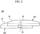
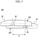
- FIGS. 2 and 3 are cut-away perspective views of the slide gate including the valve plate illustrated in FIG. 1 , and FIG. 2 illustrates an opened state and FIG. 3 illustrates a closed state.
- valve plates 110 and 120 of the exemplary embodiment are stacked on each other to constitute a slide gate 200. That is, the slide gate 200 is constituted by an upper valve plate 110 and a lower valve plate 120 and two valve plates 110 and 120 are configured similarly to the valve plate 100 illustrated in FIG. 1 .
- the upper valve plate 110 is disposed to be opposite to the lower valve plate 120 at left and right sides thereof. That is, when the fourth short side 24 and the fifth short side 25 of the lower valve plate 120 are positioned toward the right side, the fourth short side 24 and the fifth short side 25 of the upper valve plate 110 are positioned toward the left side.
- the orifice 19 of the upper valve plate 110 is connected with an upper nozzle (not illustrated) to maintain a state in which the molten steel continuously flows.
- the slide gate 200 becomes an opened state and when the lower valve plate 120 slides to clog the orifice 19 of the upper valve plate 110, the slide gate 200 is switched to a closed state.
- the valve plate 100 of the exemplary embodiment has the heptangular shape to minimize stress generation as compared with a valve plate having a different shape in the related art.
- a valve plate without the first long side 11 and the second long side 12 has a pentagonal shape and the valve plate 100 of the exemplary embodiment may have a lower maximum stress value than the pentagonal valve plate.
- Table 1 given below shows a numerical analysis result having a maximum stress size depending on a ratio of ⁇ 1 and ⁇ 2 and a change of slopes ⁇ of the first short side 21 and the second short side 22 under a condition in which the same clamp pressure is applied.
- Maximum stress means maximum tensile stress applied to the valve plate 100 and as the size of the maximum stress is smaller, less cracks are generated.
- Maximum stress (MPa) 438.8 421.5 415 398.3 382.5 Sample No.
- sample 1 is the pentagonal valve plate and samples 2 to 9 are the heptangular valve plates. Under a condition in which the same clamping pressure is applied to samples 1 to 9, it can be verified that maximum stress of samples 2 to 9 is reduced as compared with sample 1. In particular, as the lengths of the first long side 11 and the second long side 12 are larger than the length of the entire valve plate 100, it can be seen that the maximum stress is significantly reduced.
- a length ratio ( ⁇ 1: ⁇ 2) of the first part 11 a and the second part 11 b that bidivide the first long side 11 and a ratio (k1:k2) of the bottom side and the height of the right-angled triangle having the fourth short side 24 as the oblique side are associated with the stress of the valve plate 100.
- FIG. 4 is a graph showing a numerical analysis result of a maximum stress size depending on a change of ⁇ 1/ ⁇ 2 with respect to samples 10 to 13.
- Table 2 given below shows shape characteristics of samples 10 to 13. (Table 2) Slope (°) of first short side k1:k2 Diameter (mm) of orifice Length (mm) of third short side Sample 10 22.04 1.55:1 35 90 Sample 11 12.93 1.54:1 60 125 Sample 12 19.54 1.92:1 55 100 Sample 13 19.29 2.29:1 85 135
- a lower limit of the ⁇ 1/ ⁇ 2 value is 2 and the ⁇ 1/ ⁇ 2 value may increase within an implementable range, but as the ⁇ 1/ ⁇ 2 value increases, more materials are used, and as a result, ⁇ 1/ ⁇ 2 may be set to satisfy a range of 2 to 3.5.
- FIG. 5 is a graph showing a numerical analysis result of a maximum stress size depending on a change of k1/k2 with respect to samples 14 to 17.
- Table 3 given below shows shape characteristics of samples 14 to 17. (Table 3) ⁇ 1: ⁇ 2 Slope (°) of first short side Diameter (mm) of orifice Length (mm) of third short side Sample 14 3:1 22.04 35 90 Sample 15 1.17:1 12.93 60 125 Sample 16 2.08:1 19.54 55 100 Sample 17 2.11:1 19.29 85 135
- k1/k2 may be set to satisfy a range of 1.5 to 2.75.
- a total length and a total width and the length ⁇ 1 of the first parts 11 a and 21 a and the length of the third short side 23 are associated with a stroke length which is a movement distance of the lower valve plate 120 when the slide gate 200 is actuated.
- the total length of the valve plate 100 is represented as D1 and the total width is represented as D2.
- the stroke length of the lower valve plate 120 is represented as S.
- the total length D1 of the valve plate 100 may be set to satisfy a range of twice or three times larger than the stroke length S.
- the total length D1 of the valve plate 100 is twice less than the stroke length S, since the length of the valve plate 100 is not sufficient according to an actuation direction of the valve plate 100, the lower valve plate 120 may not clog the orifice 19 of the upper valve plate 110 in the closed state, and as a result, there is a possibility that the molten steel will leak.
- the total length D1 of the valve plate 100 is three times larger than the stroke length S, manufacturing cost of the valve plate 100 may increase due to excessive use of materials.
- the total width D2 of the valve plate 100 may be set to satisfy a range of one to 1.5 times larger than the stroke length S.
- the total width D2 of the valve plate 100 is once less than the stroke length S, since the first and second long sides 11 and 12 and the orifice 19 are positioned excessively close to each other, there is a possibility that the crack will be generated in a vertical direction from the orifice 19. Meanwhile, when the total width D2 of the valve plate 100 is 1.5 times larger than the stroke length S, there is no change in performance of the valve plate 100, but the used materials may be wasted.
- the length ⁇ 1 of the first parts 11 a and 12a may be set to satisfy a range of 0.2 to 0.5 times smaller than the stroke length S.
- the length of the third short side 23 may be set to satisfy a range of 0.5 times or once as large as the stroke length S.
- the valve plate 100 of the exemplary embodiment has the heptangular shape and slopes and lengths of the first short side 21, the second short side 22, the fourth short side 24, and the fifth short side 25 to which the clamping force is applied are optimized to reduce the maximum stress generated on the valve plate 100. As a result, the generation of the crack of the valve plate 100 is suppressed to improve a use life-span of the valve plate 100.
Landscapes
- Engineering & Computer Science (AREA)
- Mechanical Engineering (AREA)
- Casting Support Devices, Ladles, And Melt Control Thereby (AREA)
Abstract
Description
- The present invention relates to a slide gate positioned between a ladle and a tundish to control a flow rate of molten steel, and more particularly, to a valve plate for a slide gate, which is capable of minimizing generation of stress and cracks.
- In continuous casting, molten steel refined in a ladle is transported to a tundish and in this case, a slide gate serving as a valve is mounted between the ladle and tundish in order to control a flow rate of the molten steel. The slide gate is constituted by an upper valve plate and a lower valve plate each having an orifice.
- The slide gate becomes an opened state when two orifices are at the same position and a closed state when the lower valve plate becomes a closed state when the lower valve plate slides and the orifice of the upper valve plate is clogged by the lower valve plate. In addition, an opening degree of the orifice of the upper valve plate is controlled according to a movement degree of the lower valve plate to control the flow rate of the molten steel.
- A peripheral temperature of the orifice of the valve plate reaches 1600°C, while an outer temperature of the valve plate is approximately 400°C. Accordingly, a temperature gradient occurs toward a periphery of the valve plate of the orifice and the crack is generated in the valve plate due to a difference in thermal expansion.
- A method is used, which clamps an exterior of the valve plate by using a tool such as a stopper, or the like in order to suppress the generation of the crack. However, stress generated according to a shape of the valve plate varies when the same clamping force is applied, and as a result, shape enhancement of the valve plate is required for minimizing the generation of the stress.
- The present invention has been made in an effort to provide a slide gate and a valve plate for the slide gate, which are capable of minimizing generation of stress and cracks generated on the valve plate by optimizing a shape of the valve plate.
- An exemplary embodiment of the present invention provides a valve plate for a slide gate, wherein: the valve plate has a heptangular shape including a first long side and a second long side facing each other in parallel, a first short side and a second short side slantly contacting one end of the first long side and one end of the second long side, respectively, a third short side connecting the first short side and the second short side, and a fourth short side and a fifth short side slantly contacting the other ends of the first long side and the second long side, respectively. The valve plate for the slide gate is symmetric based on a central line parallel to the first long side and the second long side while maintaining the same distance as the first long side and the second long side and an orifice may be formed on the central line.
- The first long side and the second long side may have the same length, and the lengths of the first long side and the second long side may be larger than the length of each of the first to fifth short sides. The first short side and the second short side may have the same length, and the length of the third short side may be smaller than the length of each of the first and second short sides. Corners contacting the fourth short side and the fifth short side may be rounded.
- The orifice may be positioned between the first long side and the second long side, and each of the first long side and the second long side may be bidivded into a first part having a length of δ1 and a second part having a length of δ2 by a virtual vertical line which is orthogonal to the central line and meets a center of a shape of the orifice. The first long side and the second long side may be formed to satisfy the following condition.

- A virtual right-angled triangle having each of the fourth short side and the fifth short side as an oblique side may be configured on the valve plate, and the right-angled triangle may have a bottom side having a length k1 and a height having a length of k2. The fourth short side and the fifth short side may be formed to satisfy the following condition.

- Another exemplary embodiment of the present invention provides a slide gate including a valve plate having the aforementioned configuration as an upper valve plate and a lower valve plate, wherein the lower valve plate moves by a stroke length of S to open and close an orifice of the upper valve plate.
- A total length D1 of the valve plate may belong to a range of twice to three times larger than the stroke length S and a total width D2 of the valve plate may belong to a range of once to 1.5 times larger than the stroke length S.
- According to exemplary embodiments of the present invention, a valve plate for a slide gate has a heptangular shape and slopes and lengths of a first short side, a second short side, a fourth short side, and a fifth short side to which clamping force is applied are optimized to reduce maximum stress generated on the valve plate. As a result, generation of a crack of the valve plate is suppressed to improve a use life-span of the valve plate.
-
-
FIG. 1 is a perspective view illustrating a valve plate for a slide gate according to an exemplary embodiment of the present invention. -
FIGS. 2 and3 are cut-away perspective views of the slide gate including the valve plate illustrated inFIG. 1 . -
FIG. 4 is a graph showing a numerical analysis result of a maximum stress size depending on a change of δ1/δ2. -
FIG. 5 is a graph showing a numerical analysis result of a maximum stress size depending on a change of k1/k2. - The present invention will be described more fully hereinafter with reference to the accompanying drawings, in which exemplary embodiments of the invention are shown. As those skilled in the art would realize, the described embodiments may be modified in various different ways, all without departing from the spirit or scope of the present invention.
-
FIG. 1 is a perspective view illustrating a valve plate for a slide gate according to an exemplary embodiment of the present invention. - Referring to
FIG. 1 , thevalve plate 100 according to the exemplary embodiment as a heptangular plate having a predetermined thickness includes acircular orifice 19 for discharging molten steel. - In detail, the
valve plate 100 includes a firstlong side 11 and a secondlong side 12 facing each other in parallel, a firstshort side 21 and a secondshort side 22 slantly contacting one end of the firstlong side 11 and one end of the secondlong side 12, respectively, a thirdshort side 23 orthogonal to the firstlong side 11 and connecting the firstshort side 21 and the secondshort side 22, and a fourthshort side 24 and a fifthshort side 25 slantly contacting the other ends of the firstlong side 11 and the secondlong side 12, respectively. - The first
long side 11 and the secondlong side 12 have the same length and the lengths of the firstlong side 11 and the secondlong side 12 are larger than respective lengths of the first to fifthshort sides 21 to 25. - Based on
FIG. 1 , the firstshort side 21 and the secondshort side 22 slantly contact left ends of the firstlong side 11 and the secondlong side 12, respectively and the thirdshort side 23 connects the firstshort side 21 and the secondshort side 22. The firstshort side 21 and the secondshort side 22 have the same length and the length of the thirdshort side 23 may be smaller than the respective lengths of the firstshort side 21 and the secondshort side 22. - Based on
FIG. 1 , the fourthshort side 24 and the fifthshort side 25 slantly contact right ends of the firstlong side 11 and the secondlong side 12, respectively and the fourthshort side 24 and the fifthshort side 25 have the same length. Corners contacting the fourthshort side 24 and the fifthshort side 25 are not formed to be pointed, but may be rounded at a predetermined curvature. - The
valve plate 100 has a heptangular shape in which a diamond shape contacts one side of a central square and a triangular shape contacts the other side of the central square part. In this case, all corners where the firstlong side 11 and the secondlong side 12 and the first to fifthshort sides 21 to 25 contact each other are rounded to suppress stress concentration on the corners. - A virtual central line C-C which is parallel to the first
long side 11 and the secondlong side 12 while maintaining the same distance as the firstlong side 11 and the secondlong side 12 may be configured on thevalve plate 100. Thevalve plate 100 is symmetric based on the central line C-C (vertically symmetric based onFIG. 1 ) and theorifice 19 is positioned on the central line C-C. In particular, the center of a shape of theorifice 19 is positioned on the central line C-C. Theorifice 19 does not deviate between the firstlong side 11 and the secondlong side 12. - A virtual vertical line D-D which meets the center of the shape of the
orifice 19 and is orthogonal to the central line C-C may be configured on thevalve plate 100. The firstlong side 11 and the secondlong side 12 are bidivided intofirst parts second parts first parts second parts first parts short side 21 and the secondshort side 22 and thesecond parts short side 24 and the fifthshort side 25. - The length δ1 of the
first parts second parts orifice 19 is positioned closer to the fourthshort side 24 and the fifthshort side 25 than the firstshort side 21 and the secondshort side 22. The firstshort side 21 has a slope of an acute angle with respect to the firstlong side 11 and the secondshort side 22 has the same slope of the acute angle with respect to the secondlong side 12. InFIG. 1 , the slopes of the firstshort side 21 and the secondshort side 22 are represented as θ. - Further, a virtual right-angled triangle may be configured on the
valve plate 100, in which each of the fourthshort side 24 and the fifthshort side 25 has an oblique side. A bottom side k1 of the right-angled triangle is parallel to the central line C-C and a part of the bottom side overlaps with the central line C-C. A height k2 of the right-angled triangle is parallel to the vertical line D-D. The slopes of the fourthshort side 24 and the fifthshort side 25 are determined by k1 and k2 values. - The first
short side 21, the secondshort side 22, the fourthshort side 24, and the fifthshort side 25 at the center of thevalve plate 100 is a part that contacts a stopper of a clamping device (not illustrated) to receive clamping force from the clamping device. In addition, a surface pressure depending on a weight of the molten steel is applied onto an entire surface of thevalve plate 100. -
FIGS. 2 and3 are cut-away perspective views of the slide gate including the valve plate illustrated inFIG. 1 , andFIG. 2 illustrates an opened state andFIG. 3 illustrates a closed state. - Referring to
FIGS. 1 to 3 , twovalve plates slide gate 200. That is, theslide gate 200 is constituted by anupper valve plate 110 and alower valve plate 120 and twovalve plates valve plate 100 illustrated inFIG. 1 . - The
upper valve plate 110 is disposed to be opposite to thelower valve plate 120 at left and right sides thereof. That is, when the fourthshort side 24 and the fifthshort side 25 of thelower valve plate 120 are positioned toward the right side, the fourthshort side 24 and the fifthshort side 25 of theupper valve plate 110 are positioned toward the left side. - The
orifice 19 of theupper valve plate 110 is connected with an upper nozzle (not illustrated) to maintain a state in which the molten steel continuously flows. When theorifice 19 of thelower valve plate 120 overlaps with theorifice 19 of theupper valve plate 110, theslide gate 200 becomes an opened state and when thelower valve plate 120 slides to clog theorifice 19 of theupper valve plate 110, theslide gate 200 is switched to a closed state. - Referring back to
FIG. 1 , thevalve plate 100 of the exemplary embodiment has the heptangular shape to minimize stress generation as compared with a valve plate having a different shape in the related art. For example, a valve plate without the firstlong side 11 and the secondlong side 12 has a pentagonal shape and thevalve plate 100 of the exemplary embodiment may have a lower maximum stress value than the pentagonal valve plate. - Table 1 given below shows a numerical analysis result having a maximum stress size depending on a ratio of δ1 and δ2 and a change of slopes θ of the first
short side 21 and the secondshort side 22 under a condition in which the same clamp pressure is applied. Maximum stress means maximum tensile stress applied to thevalve plate 100 and as the size of the maximum stress is smaller, less cracks are generated.(Table 1) Sample No. 1 2 3 4 5 δ1:δ2 0:0 0:1 1:1 1:3.1 1.5:1 θ(°) 8 11 13 15 16 Maximum stress (MPa) 438.8 421.5 415 398.3 382.5 Sample No. 6 7 8 9 δ1:δ2 2:1 2.5:1 3:1 3.3:1 θ(°) 20 25 30 35 Maximum stress (MPa) 360.8 358.6 358.6 357.3 sample 1 is the pentagonal valve plate andsamples 2 to 9 are the heptangular valve plates. Under a condition in which the same clamping pressure is applied tosamples 1 to 9, it can be verified that maximum stress ofsamples 2 to 9 is reduced as compared withsample 1. In particular, as the lengths of the firstlong side 11 and the secondlong side 12 are larger than the length of theentire valve plate 100, it can be seen that the maximum stress is significantly reduced. - It is appreciated that such a result is that as the lengths of the first long side and the second long side are larger than the length of the valve plate, a horizontal component of the clamping pressure increases under the condition in which the same clamping pressure is applied, and as a result, stress generated due to thermal expansion is more suppressed.
- Further, in the
valve plate 100 of the exemplary embodiment, a length ratio (δ1:δ2) of thefirst part 11 a and thesecond part 11 b that bidivide the firstlong side 11 and a ratio (k1:k2) of the bottom side and the height of the right-angled triangle having the fourthshort side 24 as the oblique side are associated with the stress of thevalve plate 100. -
FIG. 4 is a graph showing a numerical analysis result of a maximum stress size depending on a change of δ1/δ2 with respect tosamples 10 to 13. Table 2 given below shows shape characteristics ofsamples 10 to 13.(Table 2) Slope (°) of first short side k1:k2 Diameter (mm) of orifice Length (mm) of third short side Sample 10 22.04 1.55:1 35 90 Sample 1112.93 1.54:1 60 125 Sample 1219.54 1.92:1 55 100 Sample 1319.29 2.29:1 85 135 - As shown in
FIG. 4 , as the δ1/δ2 value increases with respect to all ofsamples 10 to 13, it can be seen that the maximum stress generated on thevalve plate 100 decreases. An effect may be acquired, in which the maximum stress of thevalve plate 100 decreases when the δ1/δ2 value is 2 or more and in particular, the maximum stress does not show a large variation when the δ1/δ2 value is 2 or more insamples 11 to 13. - In the
valve plate 100, a lower limit of the δ1/δ2 value is 2 and the δ1/δ2 value may increase within an implementable range, but as the δ1/δ2 value increases, more materials are used, and as a result, δ1/δ2 may be set to satisfy a range of 2 to 3.5. -
FIG. 5 is a graph showing a numerical analysis result of a maximum stress size depending on a change of k1/k2 with respect tosamples 14 to 17. Table 3 given below shows shape characteristics ofsamples 14 to 17.(Table 3) δ1:δ2 Slope (°) of first short side Diameter (mm) of orifice Length (mm) of third short side Sample 14 3:1 22.04 35 90 Sample 151.17:1 12.93 60 125 Sample 162.08:1 19.54 55 100 Sample 172.11:1 19.29 85 135 - As shown in
FIG. 5 , as the k1/k2 value decreases with respect to all ofsamples 14 to 17, it can be seen that the maximum stress generated on thevalve plate 100 decreases. An effect may be acquired, in which when the k1/k2 value is 2.75 or less, the maximum stress of thevalve plate 100 decreases and it is impossible to manufacture a sample having k1/k2 of 1.5 or less. Accordingly, k1/k2 may be set to satisfy a range of 1.5 to 2.75. - Meanwhile, in the
valve plate 100 of the exemplary embodiment, a total length and a total width and the length δ1 of thefirst parts 11 a and 21 a and the length of the thirdshort side 23 are associated with a stroke length which is a movement distance of thelower valve plate 120 when theslide gate 200 is actuated. InFIG. 1 , the total length of thevalve plate 100 is represented as D1 and the total width is represented as D2. In addition, inFIG. 3 , the stroke length of thelower valve plate 120 is represented as S. - The total length D1 of the
valve plate 100 may be set to satisfy a range of twice or three times larger than the stroke length S. When the total length D1 of thevalve plate 100 is twice less than the stroke length S, since the length of thevalve plate 100 is not sufficient according to an actuation direction of thevalve plate 100, thelower valve plate 120 may not clog theorifice 19 of theupper valve plate 110 in the closed state, and as a result, there is a possibility that the molten steel will leak. Meanwhile, when the total length D1 of thevalve plate 100 is three times larger than the stroke length S, manufacturing cost of thevalve plate 100 may increase due to excessive use of materials. - The total width D2 of the
valve plate 100 may be set to satisfy a range of one to 1.5 times larger than the stroke length S. When the total width D2 of thevalve plate 100 is once less than the stroke length S, since the first and secondlong sides orifice 19 are positioned excessively close to each other, there is a possibility that the crack will be generated in a vertical direction from theorifice 19. Meanwhile, when the total width D2 of thevalve plate 100 is 1.5 times larger than the stroke length S, there is no change in performance of thevalve plate 100, but the used materials may be wasted. - The length δ1 of the
first parts short side 23 may be set to satisfy a range of 0.5 times or once as large as the stroke length S. - As described above, the
valve plate 100 of the exemplary embodiment has the heptangular shape and slopes and lengths of the firstshort side 21, the secondshort side 22, the fourthshort side 24, and the fifthshort side 25 to which the clamping force is applied are optimized to reduce the maximum stress generated on thevalve plate 100. As a result, the generation of the crack of thevalve plate 100 is suppressed to improve a use life-span of thevalve plate 100. - While this invention has been described in connection with what is presently considered to be practical exemplary embodiments, it is to be understood that the invention is not limited to the disclosed embodiments, but, on the contrary, is intended to cover various modifications and equivalent arrangements included within the spirit and scope of the appended claims.
Claims (11)
- A valve plate for a slide gate, wherein:the valve plate has a heptangular shape including a first long side and a second long side facing each other in parallel, a first short side and a second short side slantly contacting one end of the first long side and one end of the second long side, respectively, a third short side connecting the first short side and the second short side, and a fourth short side and a fifth short side slantly contacting the other ends of the first long side and the second long side, respectively, andthe valve plate is symmetric based on a central line parallel to the first long side and the second long side while maintaining the same distance as the first long side and the second long side and an orifice is formed on the central line.
- The valve plate of claim 1, wherein:the first long side and the second long side have the same length, andthe lengths of the first long side and the second long side are larger than the length of each of the first to fifth short sides.
- The valve plate of claim 2, wherein:the first short side and the second short side have the same length, andthe length of the third short side is smaller than the length of each of the first and second short sides.
- The valve plate of claim 3, wherein:corners contacting the fourth short side and the fifth short side are rounded.
- The valve plate of claim 1, wherein:the orifice is positioned between the first long side and the second long side, andeach of the first long side and the second long side is bidivded into a first part having a length of δ1 and a second part having a length of δ2 by a virtual vertical line which is orthogonal to the central line and meets a center of a shape of the orifice.
- The valve plate of claim 5, wherein:the first long side and the second long side are formed to satisfy the following condition.

- The valve plate of claim 1, wherein:a virtual right-angled triangle having each of the fourth short side and the fifth short side as an oblique side is configured on the valve plate, andthe right-angled triangle has a bottom side having a length k1 and a height having a length of k2.
- The valve plate of claim 7, wherein:the fourth short side and the fifth short side are formed to satisfy the following condition.

- A slide gate including a valve plate of any one of claim 1 to claim 8 as an upper valve plate and a lower valve plate, wherein:the lower valve plate moves by a stroke length of S to open and close an orifice of the upper valve plate.
- The slide gate of claim 9, wherein:a total length D1 of the valve plate belongs to a range of twice to three times larger than the stroke length S.
- The slide gate of claim 10, wherein:a total width D2 of the valve plate belongs to a range of once to 1.5 times larger than the stroke length S.
Applications Claiming Priority (2)
| Application Number | Priority Date | Filing Date | Title |
|---|---|---|---|
| KR1020140013850A KR101520038B1 (en) | 2014-02-06 | 2014-02-06 | Slide gate and valve plate for slide gate |
| PCT/KR2014/008778 WO2015119351A1 (en) | 2014-02-06 | 2014-09-22 | Slide gate and valve plate for slide gate |
Publications (3)
| Publication Number | Publication Date |
|---|---|
| EP3103564A1 true EP3103564A1 (en) | 2016-12-14 |
| EP3103564A4 EP3103564A4 (en) | 2017-08-30 |
| EP3103564B1 EP3103564B1 (en) | 2019-11-06 |
Family
ID=53394651
Family Applications (1)
| Application Number | Title | Priority Date | Filing Date |
|---|---|---|---|
| EP14881865.1A Active EP3103564B1 (en) | 2014-02-06 | 2014-09-22 | Slide gate and valve plate for slide gate |
Country Status (5)
| Country | Link |
|---|---|
| EP (1) | EP3103564B1 (en) |
| KR (1) | KR101520038B1 (en) |
| CN (1) | CN105980085A (en) |
| BR (1) | BR112016018017B1 (en) |
| WO (1) | WO2015119351A1 (en) |
Families Citing this family (3)
| Publication number | Priority date | Publication date | Assignee | Title |
|---|---|---|---|---|
| KR102066791B1 (en) * | 2018-05-18 | 2020-01-15 | 서광공업 주식회사 | Gate valve |
| KR102622383B1 (en) * | 2022-04-20 | 2024-01-10 | 조선내화 주식회사 | Automatic clamping device for valve plate for slide gate using cam |
| KR102608857B1 (en) | 2022-04-20 | 2023-12-04 | 조선내화 주식회사 | Valve plate for slide gate with improved structure and slide gate using them |
Family Cites Families (13)
| Publication number | Priority date | Publication date | Assignee | Title |
|---|---|---|---|---|
| JP2605079Y2 (en) * | 1993-01-28 | 2000-06-19 | 品川白煉瓦株式会社 | Plate brick of slide valve for molten metal flow control |
| JP2954493B2 (en) * | 1994-12-12 | 1999-09-27 | 品川白煉瓦株式会社 | Plate brick fixing mechanism for slide valve |
| JPH10137922A (en) * | 1996-10-31 | 1998-05-26 | Kawasaki Refract Co Ltd | Metal frame for sliding nozzle plate |
| JP2001062560A (en) * | 1999-08-26 | 2001-03-13 | Shinagawa Refract Co Ltd | Cushion material for plate for sliding gate type valve device |
| UA72568C2 (en) * | 1999-12-10 | 2005-03-15 | Везувіус Крусібл Компані | Refractory plate for a slide gate valve controlling the melt flow |
| TW526315B (en) * | 2001-03-06 | 2003-04-01 | Vesuvius Crucible Co | Process for repairing a crack resistant valve plate and plate so repaired |
| JP2004174582A (en) * | 2002-11-28 | 2004-06-24 | Tokyo Yogyo Co Ltd | Plate for sliding nozzle |
| JP4456363B2 (en) * | 2003-12-16 | 2010-04-28 | 東京窯業株式会社 | Sliding nozzle plate |
| KR20100046726A (en) * | 2008-10-28 | 2010-05-07 | 조선내화 주식회사 | Sliding plate for molten metal molding |
| CN201333522Y (en) * | 2008-12-16 | 2009-10-28 | 阳泉市下千耐火材料有限公司 | Sliding brick for controlling flowing speed of molten steel |
| JP4801222B1 (en) * | 2010-12-03 | 2011-10-26 | 黒崎播磨株式会社 | Sliding nozzle plate |
| CN102649645A (en) * | 2011-02-23 | 2012-08-29 | 武汉武钢维苏威高级陶瓷有限公司 | Refractory material |
| CN202185582U (en) * | 2011-07-18 | 2012-04-11 | 卫辉熔金高温材料有限责任公司 | Sliding plate brick with positioning slots |
-
2014
- 2014-02-06 KR KR1020140013850A patent/KR101520038B1/en active Active
- 2014-09-22 EP EP14881865.1A patent/EP3103564B1/en active Active
- 2014-09-22 WO PCT/KR2014/008778 patent/WO2015119351A1/en not_active Ceased
- 2014-09-22 CN CN201480074861.2A patent/CN105980085A/en active Pending
- 2014-09-22 BR BR112016018017-8A patent/BR112016018017B1/en active IP Right Grant
Also Published As
| Publication number | Publication date |
|---|---|
| CN105980085A (en) | 2016-09-28 |
| EP3103564A4 (en) | 2017-08-30 |
| WO2015119351A1 (en) | 2015-08-13 |
| KR101520038B1 (en) | 2015-05-13 |
| EP3103564B1 (en) | 2019-11-06 |
| BR112016018017B1 (en) | 2020-03-17 |
Similar Documents
| Publication | Publication Date | Title |
|---|---|---|
| EP3103564B1 (en) | Slide gate and valve plate for slide gate | |
| KR101360564B1 (en) | Mold in continuous casting | |
| KR20180073378A (en) | Sealing Device for Secondary Battery | |
| WO2009128282A1 (en) | Immersion nozzle for continuous casting | |
| BR112019013288A2 (en) | tempered limb and tempered limb manufacturing method | |
| KR101030886B1 (en) | Molding Mold for Curved Tempered Glass | |
| EP2380681A1 (en) | Nozzle for discharging molten metal | |
| EP3408043B1 (en) | Sliding gate valve plate | |
| WO2017133349A1 (en) | Reinforcer used for plate heat exchanger and plate heat exchanger | |
| US5961874A (en) | Flat formed submerged entry nozzle for continuous casting of steel | |
| CN103476520B (en) | Latch plate and comprising the slip dead lock at outlet place of container of metal bath | |
| DE112012002560T5 (en) | Liquid steel caster | |
| US2433803A (en) | Sectional hot top | |
| KR20020064338A (en) | Crack resistant valve plate for a slide gate valve | |
| US7290685B2 (en) | Nozzle plate for a sliding nozzle apparatus | |
| US5626164A (en) | Crack resistant valve plate assembly for a molten metal slide gate valve | |
| MX2022006833A (en) | Refractory casting nozzle for a changing device arranged at the outlet of a metallurgical vessel. | |
| EP2478980A1 (en) | Nozzle for discharging molten metal | |
| US20150266025A1 (en) | Liquid feed device and valve system | |
| CN216917045U (en) | Section bar with protection architecture | |
| KR20200035551A (en) | Refractory for sliding gate member of tundish | |
| CN205362580U (en) | Combination casting die utensil | |
| JP7712562B2 (en) | Submerged Entry Nozzle | |
| CN202968365U (en) | Auxiliary limiting system | |
| JP6862657B2 (en) | Sliding gate plate |
Legal Events
| Date | Code | Title | Description |
|---|---|---|---|
| PUAI | Public reference made under article 153(3) epc to a published international application that has entered the european phase |
Free format text: ORIGINAL CODE: 0009012 |
|
| STAA | Information on the status of an ep patent application or granted ep patent |
Free format text: STATUS: REQUEST FOR EXAMINATION WAS MADE |
|
| 17P | Request for examination filed |
Effective date: 20160802 |
|
| AK | Designated contracting states |
Kind code of ref document: A1 Designated state(s): AL AT BE BG CH CY CZ DE DK EE ES FI FR GB GR HR HU IE IS IT LI LT LU LV MC MK MT NL NO PL PT RO RS SE SI SK SM TR |
|
| AX | Request for extension of the european patent |
Extension state: BA ME |
|
| DAX | Request for extension of the european patent (deleted) | ||
| A4 | Supplementary search report drawn up and despatched |
Effective date: 20170728 |
|
| RIC1 | Information provided on ipc code assigned before grant |
Ipc: B22D 41/22 20060101AFI20170724BHEP Ipc: B22D 41/28 20060101ALI20170724BHEP |
|
| GRAP | Despatch of communication of intention to grant a patent |
Free format text: ORIGINAL CODE: EPIDOSNIGR1 |
|
| STAA | Information on the status of an ep patent application or granted ep patent |
Free format text: STATUS: GRANT OF PATENT IS INTENDED |
|
| RIC1 | Information provided on ipc code assigned before grant |
Ipc: B22D 41/22 20060101AFI20190307BHEP Ipc: B22D 41/28 20060101ALI20190307BHEP |
|
| INTG | Intention to grant announced |
Effective date: 20190402 |
|
| GRAS | Grant fee paid |
Free format text: ORIGINAL CODE: EPIDOSNIGR3 |
|
| GRAA | (expected) grant |
Free format text: ORIGINAL CODE: 0009210 |
|
| STAA | Information on the status of an ep patent application or granted ep patent |
Free format text: STATUS: THE PATENT HAS BEEN GRANTED |
|
| AK | Designated contracting states |
Kind code of ref document: B1 Designated state(s): AL AT BE BG CH CY CZ DE DK EE ES FI FR GB GR HR HU IE IS IT LI LT LU LV MC MK MT NL NO PL PT RO RS SE SI SK SM TR |
|
| REG | Reference to a national code |
Ref country code: GB Ref legal event code: FG4D |
|
| REG | Reference to a national code |
Ref country code: CH Ref legal event code: EP Ref country code: AT Ref legal event code: REF Ref document number: 1198077 Country of ref document: AT Kind code of ref document: T Effective date: 20191115 |
|
| REG | Reference to a national code |
Ref country code: IE Ref legal event code: FG4D |
|
| REG | Reference to a national code |
Ref country code: DE Ref legal event code: R096 Ref document number: 602014056565 Country of ref document: DE |
|
| REG | Reference to a national code |
Ref country code: NL Ref legal event code: MP Effective date: 20191106 |
|
| REG | Reference to a national code |
Ref country code: LT Ref legal event code: MG4D |
|
| PG25 | Lapsed in a contracting state [announced via postgrant information from national office to epo] |
Ref country code: NO Free format text: LAPSE BECAUSE OF FAILURE TO SUBMIT A TRANSLATION OF THE DESCRIPTION OR TO PAY THE FEE WITHIN THE PRESCRIBED TIME-LIMIT Effective date: 20200206 Ref country code: GR Free format text: LAPSE BECAUSE OF FAILURE TO SUBMIT A TRANSLATION OF THE DESCRIPTION OR TO PAY THE FEE WITHIN THE PRESCRIBED TIME-LIMIT Effective date: 20200207 Ref country code: PT Free format text: LAPSE BECAUSE OF FAILURE TO SUBMIT A TRANSLATION OF THE DESCRIPTION OR TO PAY THE FEE WITHIN THE PRESCRIBED TIME-LIMIT Effective date: 20200306 Ref country code: FI Free format text: LAPSE BECAUSE OF FAILURE TO SUBMIT A TRANSLATION OF THE DESCRIPTION OR TO PAY THE FEE WITHIN THE PRESCRIBED TIME-LIMIT Effective date: 20191106 Ref country code: BG Free format text: LAPSE BECAUSE OF FAILURE TO SUBMIT A TRANSLATION OF THE DESCRIPTION OR TO PAY THE FEE WITHIN THE PRESCRIBED TIME-LIMIT Effective date: 20200206 Ref country code: LV Free format text: LAPSE BECAUSE OF FAILURE TO SUBMIT A TRANSLATION OF THE DESCRIPTION OR TO PAY THE FEE WITHIN THE PRESCRIBED TIME-LIMIT Effective date: 20191106 Ref country code: SE Free format text: LAPSE BECAUSE OF FAILURE TO SUBMIT A TRANSLATION OF THE DESCRIPTION OR TO PAY THE FEE WITHIN THE PRESCRIBED TIME-LIMIT Effective date: 20191106 Ref country code: PL Free format text: LAPSE BECAUSE OF FAILURE TO SUBMIT A TRANSLATION OF THE DESCRIPTION OR TO PAY THE FEE WITHIN THE PRESCRIBED TIME-LIMIT Effective date: 20191106 Ref country code: LT Free format text: LAPSE BECAUSE OF FAILURE TO SUBMIT A TRANSLATION OF THE DESCRIPTION OR TO PAY THE FEE WITHIN THE PRESCRIBED TIME-LIMIT Effective date: 20191106 Ref country code: NL Free format text: LAPSE BECAUSE OF FAILURE TO SUBMIT A TRANSLATION OF THE DESCRIPTION OR TO PAY THE FEE WITHIN THE PRESCRIBED TIME-LIMIT Effective date: 20191106 |
|
| PG25 | Lapsed in a contracting state [announced via postgrant information from national office to epo] |
Ref country code: IS Free format text: LAPSE BECAUSE OF FAILURE TO SUBMIT A TRANSLATION OF THE DESCRIPTION OR TO PAY THE FEE WITHIN THE PRESCRIBED TIME-LIMIT Effective date: 20200306 Ref country code: HR Free format text: LAPSE BECAUSE OF FAILURE TO SUBMIT A TRANSLATION OF THE DESCRIPTION OR TO PAY THE FEE WITHIN THE PRESCRIBED TIME-LIMIT Effective date: 20191106 Ref country code: RS Free format text: LAPSE BECAUSE OF FAILURE TO SUBMIT A TRANSLATION OF THE DESCRIPTION OR TO PAY THE FEE WITHIN THE PRESCRIBED TIME-LIMIT Effective date: 20191106 |
|
| PG25 | Lapsed in a contracting state [announced via postgrant information from national office to epo] |
Ref country code: AL Free format text: LAPSE BECAUSE OF FAILURE TO SUBMIT A TRANSLATION OF THE DESCRIPTION OR TO PAY THE FEE WITHIN THE PRESCRIBED TIME-LIMIT Effective date: 20191106 |
|
| PG25 | Lapsed in a contracting state [announced via postgrant information from national office to epo] |
Ref country code: DK Free format text: LAPSE BECAUSE OF FAILURE TO SUBMIT A TRANSLATION OF THE DESCRIPTION OR TO PAY THE FEE WITHIN THE PRESCRIBED TIME-LIMIT Effective date: 20191106 Ref country code: ES Free format text: LAPSE BECAUSE OF FAILURE TO SUBMIT A TRANSLATION OF THE DESCRIPTION OR TO PAY THE FEE WITHIN THE PRESCRIBED TIME-LIMIT Effective date: 20191106 Ref country code: EE Free format text: LAPSE BECAUSE OF FAILURE TO SUBMIT A TRANSLATION OF THE DESCRIPTION OR TO PAY THE FEE WITHIN THE PRESCRIBED TIME-LIMIT Effective date: 20191106 Ref country code: RO Free format text: LAPSE BECAUSE OF FAILURE TO SUBMIT A TRANSLATION OF THE DESCRIPTION OR TO PAY THE FEE WITHIN THE PRESCRIBED TIME-LIMIT Effective date: 20191106 Ref country code: CZ Free format text: LAPSE BECAUSE OF FAILURE TO SUBMIT A TRANSLATION OF THE DESCRIPTION OR TO PAY THE FEE WITHIN THE PRESCRIBED TIME-LIMIT Effective date: 20191106 |
|
| REG | Reference to a national code |
Ref country code: DE Ref legal event code: R097 Ref document number: 602014056565 Country of ref document: DE |
|
| REG | Reference to a national code |
Ref country code: AT Ref legal event code: MK05 Ref document number: 1198077 Country of ref document: AT Kind code of ref document: T Effective date: 20191106 |
|
| PG25 | Lapsed in a contracting state [announced via postgrant information from national office to epo] |
Ref country code: SM Free format text: LAPSE BECAUSE OF FAILURE TO SUBMIT A TRANSLATION OF THE DESCRIPTION OR TO PAY THE FEE WITHIN THE PRESCRIBED TIME-LIMIT Effective date: 20191106 Ref country code: SK Free format text: LAPSE BECAUSE OF FAILURE TO SUBMIT A TRANSLATION OF THE DESCRIPTION OR TO PAY THE FEE WITHIN THE PRESCRIBED TIME-LIMIT Effective date: 20191106 |
|
| PLBE | No opposition filed within time limit |
Free format text: ORIGINAL CODE: 0009261 |
|
| STAA | Information on the status of an ep patent application or granted ep patent |
Free format text: STATUS: NO OPPOSITION FILED WITHIN TIME LIMIT |
|
| 26N | No opposition filed |
Effective date: 20200807 |
|
| PG25 | Lapsed in a contracting state [announced via postgrant information from national office to epo] |
Ref country code: AT Free format text: LAPSE BECAUSE OF FAILURE TO SUBMIT A TRANSLATION OF THE DESCRIPTION OR TO PAY THE FEE WITHIN THE PRESCRIBED TIME-LIMIT Effective date: 20191106 Ref country code: SI Free format text: LAPSE BECAUSE OF FAILURE TO SUBMIT A TRANSLATION OF THE DESCRIPTION OR TO PAY THE FEE WITHIN THE PRESCRIBED TIME-LIMIT Effective date: 20191106 |
|
| PG25 | Lapsed in a contracting state [announced via postgrant information from national office to epo] |
Ref country code: IT Free format text: LAPSE BECAUSE OF FAILURE TO SUBMIT A TRANSLATION OF THE DESCRIPTION OR TO PAY THE FEE WITHIN THE PRESCRIBED TIME-LIMIT Effective date: 20191106 |
|
| REG | Reference to a national code |
Ref country code: DE Ref legal event code: R119 Ref document number: 602014056565 Country of ref document: DE |
|
| PG25 | Lapsed in a contracting state [announced via postgrant information from national office to epo] |
Ref country code: MC Free format text: LAPSE BECAUSE OF FAILURE TO SUBMIT A TRANSLATION OF THE DESCRIPTION OR TO PAY THE FEE WITHIN THE PRESCRIBED TIME-LIMIT Effective date: 20191106 |
|
| REG | Reference to a national code |
Ref country code: CH Ref legal event code: PL |
|
| GBPC | Gb: european patent ceased through non-payment of renewal fee |
Effective date: 20200922 |
|
| REG | Reference to a national code |
Ref country code: BE Ref legal event code: MM Effective date: 20200930 |
|
| PG25 | Lapsed in a contracting state [announced via postgrant information from national office to epo] |
Ref country code: LU Free format text: LAPSE BECAUSE OF NON-PAYMENT OF DUE FEES Effective date: 20200922 |
|
| PG25 | Lapsed in a contracting state [announced via postgrant information from national office to epo] |
Ref country code: DE Free format text: LAPSE BECAUSE OF NON-PAYMENT OF DUE FEES Effective date: 20210401 Ref country code: FR Free format text: LAPSE BECAUSE OF NON-PAYMENT OF DUE FEES Effective date: 20200930 |
|
| PG25 | Lapsed in a contracting state [announced via postgrant information from national office to epo] |
Ref country code: CH Free format text: LAPSE BECAUSE OF NON-PAYMENT OF DUE FEES Effective date: 20200930 Ref country code: BE Free format text: LAPSE BECAUSE OF NON-PAYMENT OF DUE FEES Effective date: 20200930 Ref country code: LI Free format text: LAPSE BECAUSE OF NON-PAYMENT OF DUE FEES Effective date: 20200930 Ref country code: IE Free format text: LAPSE BECAUSE OF NON-PAYMENT OF DUE FEES Effective date: 20200922 Ref country code: GB Free format text: LAPSE BECAUSE OF NON-PAYMENT OF DUE FEES Effective date: 20200922 |
|
| PG25 | Lapsed in a contracting state [announced via postgrant information from national office to epo] |
Ref country code: MT Free format text: LAPSE BECAUSE OF FAILURE TO SUBMIT A TRANSLATION OF THE DESCRIPTION OR TO PAY THE FEE WITHIN THE PRESCRIBED TIME-LIMIT Effective date: 20191106 Ref country code: CY Free format text: LAPSE BECAUSE OF FAILURE TO SUBMIT A TRANSLATION OF THE DESCRIPTION OR TO PAY THE FEE WITHIN THE PRESCRIBED TIME-LIMIT Effective date: 20191106 |
|
| PG25 | Lapsed in a contracting state [announced via postgrant information from national office to epo] |
Ref country code: MK Free format text: LAPSE BECAUSE OF FAILURE TO SUBMIT A TRANSLATION OF THE DESCRIPTION OR TO PAY THE FEE WITHIN THE PRESCRIBED TIME-LIMIT Effective date: 20191106 |
|
| PGFP | Annual fee paid to national office [announced via postgrant information from national office to epo] |
Ref country code: TR Payment date: 20250917 Year of fee payment: 12 |