EP3103375A1 - Endoscope - Google Patents
Endoscope Download PDFInfo
- Publication number
- EP3103375A1 EP3103375A1 EP15843376.3A EP15843376A EP3103375A1 EP 3103375 A1 EP3103375 A1 EP 3103375A1 EP 15843376 A EP15843376 A EP 15843376A EP 3103375 A1 EP3103375 A1 EP 3103375A1
- Authority
- EP
- European Patent Office
- Prior art keywords
- bending
- section
- degrees
- bending section
- center
- Prior art date
- Legal status (The legal status is an assumption and is not a legal conclusion. Google has not performed a legal analysis and makes no representation as to the accuracy of the status listed.)
- Withdrawn
Links
- 238000005452 bending Methods 0.000 claims abstract description 402
- 238000003780 insertion Methods 0.000 claims abstract description 22
- 230000037431 insertion Effects 0.000 claims abstract description 22
- 238000010586 diagram Methods 0.000 description 36
- 230000009471 action Effects 0.000 description 27
- 230000008859 change Effects 0.000 description 15
- 210000003811 finger Anatomy 0.000 description 10
- 230000007935 neutral effect Effects 0.000 description 6
- 230000007423 decrease Effects 0.000 description 5
- 239000000470 constituent Substances 0.000 description 4
- 230000000694 effects Effects 0.000 description 2
- 230000007246 mechanism Effects 0.000 description 2
- 230000007704 transition Effects 0.000 description 2
- 230000008901 benefit Effects 0.000 description 1
- 238000012986 modification Methods 0.000 description 1
- 230000004048 modification Effects 0.000 description 1
- 230000001537 neural effect Effects 0.000 description 1
- 210000003813 thumb Anatomy 0.000 description 1
Images







Classifications
-
- A—HUMAN NECESSITIES
- A61—MEDICAL OR VETERINARY SCIENCE; HYGIENE
- A61B—DIAGNOSIS; SURGERY; IDENTIFICATION
- A61B1/00—Instruments for performing medical examinations of the interior of cavities or tubes of the body by visual or photographical inspection, e.g. endoscopes; Illuminating arrangements therefor
- A61B1/005—Flexible endoscopes
- A61B1/0051—Flexible endoscopes with controlled bending of insertion part
- A61B1/0052—Constructional details of control elements, e.g. handles
-
- A—HUMAN NECESSITIES
- A61—MEDICAL OR VETERINARY SCIENCE; HYGIENE
- A61B—DIAGNOSIS; SURGERY; IDENTIFICATION
- A61B1/00—Instruments for performing medical examinations of the interior of cavities or tubes of the body by visual or photographical inspection, e.g. endoscopes; Illuminating arrangements therefor
-
- A—HUMAN NECESSITIES
- A61—MEDICAL OR VETERINARY SCIENCE; HYGIENE
- A61B—DIAGNOSIS; SURGERY; IDENTIFICATION
- A61B1/00—Instruments for performing medical examinations of the interior of cavities or tubes of the body by visual or photographical inspection, e.g. endoscopes; Illuminating arrangements therefor
- A61B1/005—Flexible endoscopes
-
- A—HUMAN NECESSITIES
- A61—MEDICAL OR VETERINARY SCIENCE; HYGIENE
- A61B—DIAGNOSIS; SURGERY; IDENTIFICATION
- A61B1/00—Instruments for performing medical examinations of the interior of cavities or tubes of the body by visual or photographical inspection, e.g. endoscopes; Illuminating arrangements therefor
- A61B1/005—Flexible endoscopes
- A61B1/0051—Flexible endoscopes with controlled bending of insertion part
- A61B1/0057—Constructional details of force transmission elements, e.g. control wires
Definitions
- the present invention relates to an endoscope in which a bending operation knob for bending a bending section of an insertion section is provided in an operation section.
- An endoscope including an insertion section insertable into a subject for observing a subject that an observer cannot directly view has been used.
- the endoscope there is an endoscope in which a bending section bent by hand operation is provided in order to improve insertability of the insertion section.
- the bending section of the endoscope is bent in an up-down direction or a left-right direction by a bending operation knob provided in an operation section.
- Such an endoscope is disclosed in, for example, Japanese Patent Application Laid-Open Publication No. 2008-142199 .
- a pulley that winds an operation wire and tows and loosens the operation wire according to turning operation of the bending operation knob is provided. Positions of a center of the pulley and a turning center are shifted to prevent slack from occurring in the operation wire when the bending section is operated and make it possible to obtain satisfactory feeling in operation.
- an object of the present invention is to provide an endoscope in which, when a bending section is bent, the bending section reduces an operation force amount of a bending operation knob from a linear state and can be easily bent with a light force.
- An endoscope includes: an operation section provided on a hand side, which is a proximal end side; an insertion section extending to a distal end side from the operation section, a bending section being disposed in the insertion section; a plurality of towing members disposed in the insertion section and in the operation section from the bending section; a disk member turnably provided in the operation section and configured to turn to tow and loosen the plurality of towing members, the plurality of towing members being suspended in an outer circumference of the disk member; an operation member turnably disposed in the operation section and configured to turn the disk member to bend the bending section; and a turning shaft configured to turnably axially support the disk member and the operation member with respect to the operation section in a position decentered to the distal end side by a predetermined distance with respect to a center of the disk member in an initial state in which the bending section is linear.
- the endoscope in which, when the bending section is bent, the bending section reduces an operation force amount of a bending operation knob from the linear state and can be easily bent with a light force.
- Fig. 1 to Fig. 9 relate to a first embodiment of the present invention.
- Fig. 1 is a diagram showing an overall configuration of an endoscope.
- Fig. 2 is a schematic diagram of the endoscope showing a configuration in which a bending section is bent by a turning mechanism that turns in association with a bending operation knob.
- Fig. 3 is a schematic diagram showing a turning position of the bending operation knob at a time when the bending section is bent upward from an initial state.
- Fig. 4 is a schematic diagram showing a turning position of the bending operation knob at a time when the bending section is bent 90 degrees upward.
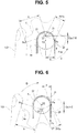
- Fig. 5 is a schematic diagram showing a turning position of the bending operation knob at a time when the bending section is bent 180 degrees upward.
- Fig. 1 is a diagram showing an overall configuration of an endoscope.
- Fig. 2 is a schematic diagram of the endoscope showing a configuration in which a bending section is bent by a turning mechanism that
- FIG. 6 is a schematic diagram showing a turning position of the bending operation knob at a time when the bending section is bent downward from the initial position.
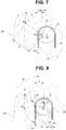
- Fig. 7 is a schematic diagram showing a turning position of the bending operation knob at a time when the bending section is bent 90 degrees downward.
- Fig. 8 is a schematic diagram showing a turning position of the bending operation knob at a time when the bending section is bent 180 degrees downward.
- Fig. 9 is a graph showing a change in an operation force amount of the bending operation knob with respect to a bending angle of the bending section.
- an endoscope 1 configured to include an insertion section 2 inserted into a subject, an operation section 3 consecutively connected to a hand side, which is a proximal end side of the insertion section 2, a universal cord 8 extended from the operation section 3, and a connector 9 provided at an extending end of the universal cord 8.
- the endoscope 1 is electrically connected to not-shown external apparatuses such as a video processor and a light source apparatus via the connector 9.
- an up-down bending operation knob 4 functioning as an operation member that is turned to bend a bending section 12 of the insertion section 2 in an up-down direction and a left-right bending operation knob 5 functioning as an operation member that is turned to bend the bending section 12 to a left-right direction are provided.
- the up-down bending operation knob 4 and the left-right bending operation knob 5 are disk-like members in which five protrusion sections (4a) for finger hook are radially provided from a center (a turning center).
- a fixing lever 6 that fixes a turning position of the up-down bending operation knob 4 and a fixing knob 7 that fixes a turning position of the left-right bending operation knob 5 are provided.
- a distal end portion 11, the bending section 12, and a flexible tube section 13 are jointly provided in order from a distal end side.
- the insertion section 2 is formed thin and long to be easily inserted into a subject.
- the bending section 12 is bent in, for example, upward, downward, left, and right four directions by turning operation of the up-down bending operation knob 4 and the left-right bending operation knob 5 to thereby change an observation direction of an image pickup unit 30 explained below provided in the distal end portion 11 and improve insertability of the distal end portion 11 in the subject.
- a sprocket 21 functioning as a disk member, which is a chain wheel, connected via a turning shaft 22 coupled to a center (a turning center) O1 of the up-down bending operation knob 4 to axially support the up-down bending operation knob 4 is disposed in the operation section 3.
- the disk member may be a pulley rather than the sprocket 21.
- the sprocket 21 is axially supported by the turning shaft 22 such that, when the bending section 12 is linear, a center 02 is decentered in a predetermined direction, in the figure, an upward side of the operation section 3 at a predetermined distance d from the turning center O1 of the up-down bending operation knob 4.
- the turning center O1 is decentered by the predetermined distance d to the distal end side along a longitudinal direction of the operation section 3 with respect to the center 02.
- center (the turning center) O1 of the turning shaft 22 and the up-down bending operation knob 4 and the center 02 of the sprocket 21 are juxtaposed along a center axis of the insertion section 2 when the bending section 12 is in a neutral linear state (a neutral initial state).
- the operation wires 25 are disposed to be inserted through the insertion section 2 from the operation section 3. Distal ends of the operation wires 25 are connected to a most-distal-end bending piece provided at a not-shown distal end in the bending section 12.
- a not-shown plurality of bending pieces are turnably coupled on an inside of the bending section 12.
- the bending section 12 is configured to bend in the up-down direction.
- the sprocket 21, the chain 23, the operation wires 25, and the like corresponding to the left-right bending operation knob 5 are provided. Therefore, when the operation wires 25 are towed and loosened according to the turning of the left-right bending operation knob 5, the bending section 12 is configured to bend in the left-right direction.
- Such a bending structure in which the plurality of bending pieces are provided in the bending section 12 is well known. Therefore, explanation of the bending structure is omitted.
- a bending angle of the bending section 12 is set to an angle same as a rotation angle of the respective bending operation knobs 4 and 5.
- a relation between a rotation angle and an operation force amount of the up-down bending operation knob 4 is illustrated.
- a relation between a rotation angle and an operation force amount of the left-right bending operation knob 5 is the same as the relation of the rotation angle and operation force amount of the up-down bending operation knob 4. Therefore, explanation concerning the left-right bending operation knob 5 is omitted without illustrating the relation.
- a point where a finger (a thumb) F of a user is hooked to the protrusion sections 4a of the up-down bending operation knob 4 is represented as an action point Pe
- a distance from the action point Pe to the turning center O1 is represented as a predetermined distance b
- a point on an extended line in a lateral direction (a horizontal direction) of the center 02 of the sprocket 21 is represented as a power point Pa.
- an operation force amount necessary for an operation force amount F 0 which is a towing force of the operation wires 25 for bending the bending section 12 at a time when the bending section 12 is further bent to the upward side from the bending angle of 0 degrees, is the following Equation (1) from a relation between a distance ⁇ 5/2 ⁇ a from the turning center O1 to the power point Pa and the distance b from the turning center O1 to the action point Pe.
- Operation force amount F 0 F 0 ⁇ ⁇ 5 / 2 ⁇ a / b
- the distance from the turning center O1 to the power point Pa can be calculated by a Pythagorean Theorem.
- the up-down bending operation knob 4 is turned 90 degrees around the turning center O1 in the counterclockwise direction.
- the sprocket 21 turns 90 degrees around the turning center O1 to approach a finger 100 of the user.
- the up-down bending operation knob 4 is turned 180 degrees around the turning center O1 counterclockwise.
- an operation force amount F90 necessary for a bending force amount F 90 for bending the bending section 12 at a time when the bending section 12 is further bent upward from the bending angle of 90 degrees is the following Equation (2) from a relation between a distance 1/2 ⁇ a from the turning center O1 to the power point Pa and the distance b from the turning center O1 to the action point Pe.
- Operation force amount F 90 F 90 ⁇ 1 / 2 ⁇ a / b
- an operation force amount F180 necessary for a bending force amount F 180 at a time when the bending angle of the bending section 12 is changed to 180 degrees shown in Fig. 5 is the following Equation (3) from the relation between the distance ⁇ 5/2 ⁇ a from the turning center O1 to the power point Pa and the distance b from the turning center O1 to the action point Pe.
- Operation force amount F 180 F 180 ⁇ ⁇ 5 / 2 ⁇ a / b
- an operation force amount F0 necessary for an operation force amount F 0 which is a towing force of the operation wires 25 for bending the bending section 12 at a time when the bending section 12 is further bent to the downward side from the bending angle of 0 degrees, is the following Equation (4) from the relation between the distance ⁇ 5/2 ⁇ a from the turning center O1 to the power point Pa and the distance b from the turning center O1 to the action point Pe.
- Operation force amount F 0 F 0 ⁇ ⁇ 5 / 2 ⁇ a / b
- the up-down bending operation knob 4 is further turned 90 degrees (-90 degrees) around the turning center O1 in the counterclockwise direction.
- the sprocket 21 turns 90 degrees (-90 degrees) around the turning center O1 to move away from the finger 100 of the user.
- the up-down bending operation knob 4 is turned 180 degrees (-180 degrees) around the turning center O1 counterclockwise.
- an operation force amount F90 (F-90) necessary for the bending force amount F 90 for bending the bending section 12 at a time when the bending section 12 is further bent downward from the bending angle of 90 degrees (-90 degrees) is the following Equation (5) from a relation between the distance a from the turning center O1 to the power point Pa and the distance b from the turning center O1 to the action point Pe.
- Operation force amount F 90 F 90 ⁇ 1 / 2 ⁇ a / b
- an operation force amount F180 (F-180) necessary for the bending force amount F 180 at a time when the bending angle of the bending section 12 is changed to 180 degrees (-180 degrees) shown in Fig. 8 is the following Equation (6) from the relation between the distance ⁇ 5/2 ⁇ a from the turning center O1 to the power point Pa and the distance b from the turning center O1 to the action point Pe.
- Operation force amount F 180 F 180 ⁇ ⁇ 5 / 2 ⁇ a / b
- the center O1 of the up-down bending operation knob 4 and the center 02 of the sprocket 21 coincide with each other and are not decentered. Therefore, the relation between the distance a from the turning center O1 to the power point Pa and the distance b from the turning center O1 to the action point Pe is invariable.
- the operation force amount F0 necessary for the operation force amount F 0 which is a towing force of the operation wires 25 for bending the bending section 12 at a time when the bending section 12 is further bent to the upward/downward sides from the bending angle of 0 degrees, in the conventional endoscope is the following Equation (7) from the relation between the distance a from the turning center O1 to the power point Pa and the distance b from the turning center O1 to the action point Pe in both the upward and downward directions.
- Operation force amount F 0 F 0 ⁇ a / b
- the operation force amount F90 (F-90) necessary for the bending force amount F 90 for bending the bending section 12 at a time when the bending section 12 is further bent upward/downward from the bending angle of 90 degrees (-90 degrees) in the conventional endoscope is the following Equation (8) because the distance a from the turning center O1 to the power point Pa and the distance b from the turning center O1 to the action point Pe do not change in both the upward and downward directions.
- Operation force amount F 90 F ⁇ 90 F 90 ⁇ a / b
- the operation force amount F180 (F-180) necessary for the bending force amount F 180 at a time when the bending angle of the bending section 12 is changed to 180 degrees (-180 degrees) in the conventional endoscope is, from the relationship, the following Equation (9) because the distance a from the turning center O1 to the power point Pa and the distance b from the turning center O1 to the action point Pe do not change in both the upward and downward directions.
- Operation force amount F 180 F ⁇ 180 F 180 ⁇ a / b
- Table 1 Transition of an operation force amount of the bending operation knob Bending angle of the bending section (Rotation angle of the bending operation knob) and operation force amount 0°/F0 90°/F90 180°/F180 Decentering is absent (general endoscope) F 0 ⁇ a/b F 90 ⁇ a/b F 180 ⁇ a/b Decentering is present in an UP direction F 0 ⁇ 5/2 ⁇ a/b F 90 ⁇ 1/2 ⁇ a/b F 180 ⁇ 5/2 ⁇ a/b Decentering is present in a DOWN direction F 0 ⁇ 5/2 ⁇ a/b F 90 ⁇ 1/2 ⁇ a/b F 180 ⁇ 5/2 ⁇ a/b
- An operation force amount at the time when the bending section 12 is bent from the bending angle of 0 degrees to the bending angle of 180 degrees (-180 degrees) changes to draw an arc to be reduced. Since the operation force amount changes to drawn an arc, the endoscope 1 does not give a sense of awkwardness to operation by the user.
- an operation force amount of an initial motion for turning the respective bending operation knobs 4 and 5 at the time when the bending section 12 is bent from the linear state (the neutral initial state) slightly increases from an operation force amount in the conventional general endoscope.
- the operation force amount immediately decreases compared with the conventional endoscope, even a surgeon with less strength can comfortably and easily bend the bending section 12.
- the endoscope 1 is configured such that, when the bending section 12 is bend from the linear state, the operation force amounts of the respective bending operation knobs 4 and 5 immediately decrease from the initial motion and the bending section 12 can be easily bent with a light force.
- the operation force amount immediately decreases. Therefore, even a surgeon with less strength can easily perform bending operation of the bending section 12.
- the endoscope 1 when the bending section 12 is bent, the operation force amount of the bending operation knob from the linear state of the bending section 12 is reduced, the bending section 12 can be easily bent with a light force, and bending operability is improved.
- the turning amounts of the respective bending operation knobs 4 and 5 are set the same as the turning amounts of the general endoscope in which the bending angle is set to 180 degrees (-180 degrees). This is for clearly explanation in terms of calculation.
- the turning amounts of the respective bending operation knobs 4 and 5 may be set to be smaller than the turning amounts in the general endoscope, that is, smaller than 180 degrees.
- Fig. 10 to Fig. 20 relate to the second embodiment of the present invention.
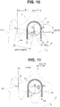
- Fig. 10 is a schematic diagram showing a turning position of a bending operation knob at a time when a bending section is bent upward from an initial state.
- Fig. 11 is a schematic diagram showing a turning position of the bending operation knob at a time when the bending section is bent 90 degrees upward.
- Fig. 12 is a schematic diagram showing a turning position of the bending operation knob at a time when the bending section is bent 180 degrees upward.
- Fig. 13 is a schematic diagram showing a turning position of the bending operation knob at a time when the bending section is bent downward from the initial state.
- Fig. 10 is a schematic diagram showing a turning position of a bending operation knob at a time when a bending section is bent upward from an initial state.
- Fig. 11 is a schematic diagram showing a turning position of the bending operation knob at a time when the bending section is bent 90 degrees upward.
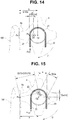
- FIG. 14 is a schematic diagram showing a turning position of the bending operation knob at a time when the bending section is bent 90 degrees downward.
- Fig. 15 is a schematic diagram showing a turning position of the bending operation knob at a time when the bending section is bent 180 degrees downward.
- Fig. 16 is a graph showing a change in an operation force amount of the bending operation knob with respect to a bending angle of the bending section.
- Fig. 17 is a schematic diagram for explaining a movement of the bending operation knob at a time when the bending section is bent 90 degrees upward from the initial state.
- Fig. 18 is a schematic diagram for explaining a movement of the bending operation knob at a time when the bending section is bent 180 degrees upward from a 90 degree state.
- Fig. 15 is a schematic diagram showing a turning position of the bending operation knob at a time when the bending section is bent 180 degrees downward.
- Fig. 16 is a graph showing a change in an operation force amount of the bending
- FIG. 19 is a schematic diagram for explaining a movement of the bending operation knob at a time when the bending section is bent 90 degrees downward from the initial state.
- Fig. 20 is a schematic diagram for explaining a movement of the bending operation knob at a time when the bending section is bent 180 degrees downward from the 90 degree state.
- the sprocket 21 and the respective bending operation knobs 4 and 5 are disposed such that centers (02 in the figure) coincide with each other. Note that, in Fig. 10 , only the up-down bending operation knob 4 is illustrated.
- the up-down bending operation knob 4 (and the left-right bending operation knob 5) is a disk-like member in which four protrusion sections 4a for finger hook are radially provided from a center (a turning center). Note that, in the respective bending operation knobs 4 and 5, the number of protrusion sections 4a is not limited to four but may be five as in the first embodiment or may be any number equal to or more than two.
- the up-down bending operation knob 4 and the sprocket 21 are axially supported such that, when the bending section 12 is linear, the center 02 is decentered in a predetermined direction, in the figure, an upward side, which is a proximal end side, of the operation section 3 by the predetermined distance d from the turning center O1 of the turning shaft 22.
- the turning center O1 is decentered by the predetermined distance d to the distal end side along the longitudinal direction of the operation section 3 with respect to the center 02 of the up-down bending operation knob 4 and the sprocket 21.
- center (the turning center) O1 of the turning shaft 22 and the center 02 of the sprocket 21 and the up-down bending operation knob 4 are juxtaposed along the center axis of the insertion section 2 when the bending section 12 is in the linear state (the neutral initial state).
- the up-down bending operation knob 4 is turned 90 degrees around the turning center O1 in the counterclockwise direction.
- an operation force amount necessary for the operation force amount F 0 which is a towing force of the operation wires 25 for bending the bending section 12 at a time when the bending section 12 is further bent to the upward side from the bending angle of 0 degrees, is the following Equation (10) from a relation between a distance ⁇ 5/2 ⁇ a from the turning center O1 to the power point Pa and a distance ⁇ (b ⁇ 2+(1/2 ⁇ a) ⁇ 2) from the turning center O1 to the action point Pe.
- Operation force amount F 0 F 0 ⁇ ⁇ 5 / 2 ⁇ a / ⁇ b ⁇ 2 + 1 / 2 ⁇ a ⁇ 2
- the distance from the turning center O1 to the power point Pa and the distance from the turning center O1 to the action point Pe can be calculated by a Pythagorean Theorem.
- the up-down bending operation knob 4 is turned 90 degrees around the turning center O1 in the counterclockwise direction.
- the up-down bending operation knob 4 and the sprocket 21 turn 90 degrees around the turning center O1 to approach the finger 100 of the user.
- the up-down bending operation knob 4 is turned 180 degrees around the turning center O1 counterclockwise.
- the operation force amount F90 necessary for the bending force amount F 90 for bending the bending section 12 at a time when the bending section 12 is further bent upward from the bending angle of 90 degrees is the following Equation (11) from a relation between the distance 1/2 ⁇ a from the turning center O1 to the power point Pa and a distance b+1/2 ⁇ a from the turning center O1 to the action point Pe.
- Operation force amount F 90 F 90 ⁇ 1 / 2 ⁇ a / b + 1 / 2 ⁇ a
- the operation force amount F180 necessary for the bending force amount F 180 at a time when the bending angle of the bending section 12 is changed to 180 degrees shown in Fig. 12 is the following Equation (12) from the relation between the distance ⁇ 5/2 ⁇ a from the turning center O1 to the power point Pa and the distance ⁇ (b ⁇ 2+(1/2 ⁇ a) ⁇ 2) from the turning center O1 to the action point Pe.
- Operation force amount F 180 F 180 ⁇ ⁇ 5 / 2 ⁇ a / ⁇ b ⁇ 2 + 1 / 2 ⁇ a ⁇ 2
- the up-down bending operation knob 4 is turned 90 degrees (-90 degrees) around the turning center O1 in the counterclockwise direction.
- the operation force amount F0 necessary for the operation force amount F 0 which is a towing force of the operation wires 25 for bending the bending section 12 at a time when the bending section 12 is further bent to the downward side from the bending angle of 0 degrees, is the following Equation (13) from the relation between the distance ⁇ 5/2 ⁇ a from the turning center O1 to the power point Pa and the distance ⁇ (b ⁇ 2+(1/2 ⁇ a) ⁇ 2) from the turning center O1 to the action point Pe.
- Operation force amount F 0 F 0 ⁇ ⁇ 5 / 2 ⁇ a / ⁇ b ⁇ 2 + 1 / 2 ⁇ a ⁇ 2
- the up-down bending operation knob 4 is further turned 90 degrees (-90 degrees) around the turning center O1 in the counterclockwise direction.
- the up-down bending operation knob 4 and the sprocket 21 turn 90 degrees (-90 degrees) around the turning center O1 to move away from the finger 100 of the user.
- the up-down bending operation knob 4 is turned 180 degrees (-180 degrees) around the turning center O1 counterclockwise.
- the operation force amount F90 (F-90) necessary for the bending force amount F 90 for bending the bending section 12 at a time when the bending section 12 is further bent downward from the bending angle of 90 degrees (-90 degrees) is the following Equation (14) from a relation between the distance 1/2 ⁇ a from the turning center O1 to the power point Pa and a distance b-1/2 ⁇ a from the turning center O1 to the action point Pe.
- Operation force amount F 90 F 90 ⁇ 1 / 2 ⁇ a / b + 1 / 2 ⁇ a
- the operation force amount F180 necessary for the bending force amount F 180 at a time when the bending angle of the bending section 12 is changed to 180 degrees (-180 degrees) shown in Fig. 15 is the following Equation (15) from the relation between the distance ⁇ 5/2 ⁇ a from the turning center O1 to the power point Pa and the distance ⁇ (b ⁇ 2+(1/2 ⁇ a) ⁇ 2) from the turning center O1 to the action point Pe.
- Operation force amount F 180 F 180 ⁇ ⁇ 5 / 2 ⁇ a / ⁇ b ⁇ 2 + 1 / 2 ⁇ a ⁇ 2
- the operation force amount F0 necessary for the operation force amount F 0 which is a towing force of the operation wires 25 for bending the bending section 12 at a time when the bending section 12 is further bent to the upward/downward sides from the bending angle of 0 degrees, in the conventional endoscope is the following Equation (16) from the relation between the distance a from the turning center O1 to the power point Pa and the distance b from the turning center O1 to the action point Pe in both the upward and downward directions.
- Operation force amount F 0 F 0 ⁇ a / b
- the operation force amount F90 necessary for the bending force amount F 90 for bending the bending section 12 at a time when the bending section 12 is further bent upward/downward from the bending angle of 90 degrees (-90 degrees) in the conventional endoscope is the following Equation (17) because the distance a from the turning center O1 to the power point Pa and the distance b from the turning center O1 to the action point Pe do not change in both the upward and downward directions.
- Operation force amount F 90 F 90 ⁇ a / b
- the operation force amount F180 necessary for the bending force amount F 180 at a time when the bending angle of the bending section 12 is changed to 180 degrees (-180 degrees) in the conventional endoscope is the following Equation (18) because the distance a from the turning center O1 to the power point Pa and the distance b from the turning center O1 to the action point Pe do not change in both the upward and downward directions.
- Operation force amount F 180 F 180 ⁇ a / b
- An operation force amount at the time when the bending section 12 is bent from the bending angle of 0 degrees to the bending angle of 180 degrees (-180 degrees) changes to draw an arc to be reduced.
- the endoscope 1 since the operation force amount changes to draw an arc, the endoscope 1 does not give a sense of awkwardness to operation by the user.
- the operation force amount immediately decreases compared with the conventional endoscope, even a surgeon with less strength can comfortably and easily bend the bending section 12.
- the endoscope 1 is configured such that, when the bending section 12 is bend from the linear state, the operation force amounts of the respective bending operation knobs 4 and 5 immediately decrease from the initial motion and the bending section 12 can be easily bent with a light force.
- the operation force amount F90 for bending the frequently-used bending section 12 to the bending angle of 90 degrees upward is reduced to 0.4 times. It is possible to easily bend the bending section 12 with an extremely light force. The bending operability is further improved.
- the turning center O1 of the turning shaft 22 is decentered by the predetermined distance d to the distal end side along the longitudinal direction of the operation section 3 with respect to the center 02. Therefore, as shown in Fig. 17 and Fig. 18 , during bending operation for bending the bending section 12 upward from the bending angle of 0 degrees to 180 degrees, the protrusion sections 4a of the up-down bending operation knob 4 turn around the turning center O1 to approach the finger 100 of the user at a predetermined distance L.
- the protrusion sections 4a of the up-down bending operation knob 4 turn around the turning center O1 to move away from the finger 100 of the user at the predetermined distance L.
Landscapes
- Health & Medical Sciences (AREA)
- Life Sciences & Earth Sciences (AREA)
- Surgery (AREA)
- Biomedical Technology (AREA)
- Medical Informatics (AREA)
- Optics & Photonics (AREA)
- Pathology (AREA)
- Radiology & Medical Imaging (AREA)
- Biophysics (AREA)
- Engineering & Computer Science (AREA)
- Physics & Mathematics (AREA)
- Heart & Thoracic Surgery (AREA)
- Nuclear Medicine, Radiotherapy & Molecular Imaging (AREA)
- Molecular Biology (AREA)
- Animal Behavior & Ethology (AREA)
- General Health & Medical Sciences (AREA)
- Public Health (AREA)
- Veterinary Medicine (AREA)
- Instruments For Viewing The Inside Of Hollow Bodies (AREA)
- Endoscopes (AREA)
Abstract
Description
- The present invention relates to an endoscope in which a bending operation knob for bending a bending section of an insertion section is provided in an operation section.
- An endoscope including an insertion section insertable into a subject for observing a subject that an observer cannot directly view has been used. As the endoscope, there is an endoscope in which a bending section bent by hand operation is provided in order to improve insertability of the insertion section. The bending section of the endoscope is bent in an up-down direction or a left-right direction by a bending operation knob provided in an operation section.
- Such an endoscope is disclosed in, for example, Japanese Patent Application Laid-Open Publication No.
2008-142199 - However, in the endoscope disclosed in Japanese Patent Application Laid-Open Publication No.
2008-142199 - Therefore, the present invention has been devised in view of the circumstances and an object of the present invention is to provide an endoscope in which, when a bending section is bent, the bending section reduces an operation force amount of a bending operation knob from a linear state and can be easily bent with a light force.
- An endoscope according to an aspect of the present invention includes: an operation section provided on a hand side, which is a proximal end side; an insertion section extending to a distal end side from the operation section, a bending section being disposed in the insertion section; a plurality of towing members disposed in the insertion section and in the operation section from the bending section; a disk member turnably provided in the operation section and configured to turn to tow and loosen the plurality of towing members, the plurality of towing members being suspended in an outer circumference of the disk member; an operation member turnably disposed in the operation section and configured to turn the disk member to bend the bending section; and a turning shaft configured to turnably axially support the disk member and the operation member with respect to the operation section in a position decentered to the distal end side by a predetermined distance with respect to a center of the disk member in an initial state in which the bending section is linear.
- According to the present invention described above, it is possible to provide the endoscope in which, when the bending section is bent, the bending section reduces an operation force amount of a bending operation knob from the linear state and can be easily bent with a light force.
-
-
Fig. 1 is a diagram showing an overall configuration of an endoscope in a first embodiment of the present invention; -
Fig. 2 is a schematic diagram of the endoscope showing a configuration in which a bending section is bent by a turning mechanism that turns in association with a bending operation knob in the first embodiment of the present invention; -
Fig. 3 is a schematic diagram showing a turning position of the bending operation knob at a time when the bending section is bent upward from an initial state in the first embodiment of the present invention; -
Fig. 4 is a schematic diagram showing a turning position of the bending operation knob at a time when the bending section is bent 90 degrees upward in the first embodiment of the present invention; -
Fig. 5 is a schematic diagram showing a turning position of the bending operation knob at a time when the bending section is bent 180 degrees upward in the first embodiment of the present invention; -
Fig. 6 is a schematic diagram showing a turning position of the bending operation knob at a time when the bending section is bent downward from the initial position in the first embodiment of the present invention; -
Fig. 7 is a schematic diagram showing a turning position of the bending operation knob at a time when the bending section is bent 90 degrees downward in the first embodiment of the present invention; -
Fig. 8 is a schematic diagram showing a turning position of the bending operation knob at a time when the bending section is bent 180 degrees downward in the first embodiment of the present invention; -
Fig. 9 is a graph showing a change in an operation force amount of the bending operation knob with respect to a bending angle of the bending section in the first embodiment of the present invention; -
Fig. 10 is a schematic diagram showing a turning position of a bending operation knob at a time when a bending section is bent upward from an initial state in a second embodiment of the present invention; -
Fig. 11 is a schematic diagram showing a turning position of the bending operation knob at a time when the bending section is bent 90 degrees upward in the second embodiment of the present invention; -
Fig. 12 is a schematic diagram showing a turning position of the bending operation knob at a time when the bending section is bent 180 degrees upward in the second embodiment of the present invention; -
Fig. 13 is a schematic diagram showing a turning position of the bending operation knob at a time when the bending section is bent downward from the initial state in the second embodiment of the present invention; -
Fig. 14 is a schematic diagram showing a turning position of the bending operation knob at a time when the bending section is bent 90 degrees downward in the second embodiment of the present invention; -
Fig. 15 is a schematic diagram showing a turning position of the bending operation knob at a time when the bending section is bent 180 degrees downward in the second embodiment of the present invention; -
Fig. 16 is a graph showing a change in an operation force amount of the bending operation knob with respect to a bending angle of the bending section in the second embodiment of the present invention; -
Fig. 17 is a schematic diagram for explaining a movement of the bending operation knob at a time when the bending section is bent 90 degrees upward from the initial state in the second embodiment of the present invention; -
Fig. 18 is a schematic diagram for explaining a movement of the bending operation knob at a time when the bending section is bent 180 degrees upward from a 90 degree state in the second embodiment of the present invention; -
Fig. 19 is a schematic diagram for explaining a movement of the bending operation knob at a time when the bending section is bent 90 degrees downward from the initial state in the second embodiment of the present invention; and -
Fig. 20 is a schematic diagram for explaining a movement of the bending operation knob at a time when the bending section is bent 180 degrees downward from the 90 degree state in the second embodiment of the present invention. - The present invention is explained below with reference to the drawings. Note that, in the respective figures referred to in the following explanation, scales are differentiated for each of components in order to show the respective components in sizes recognizable on the drawings. The present invention is not limited to only numbers of components, shapes of the components, ratios of sizes of the components, and relative positional relations of the respective components described in the figures.
-
Fig. 1 to Fig. 9 relate to a first embodiment of the present invention.Fig. 1 is a diagram showing an overall configuration of an endoscope.Fig. 2 is a schematic diagram of the endoscope showing a configuration in which a bending section is bent by a turning mechanism that turns in association with a bending operation knob.Fig. 3 is a schematic diagram showing a turning position of the bending operation knob at a time when the bending section is bent upward from an initial state.Fig. 4 is a schematic diagram showing a turning position of the bending operation knob at a time when the bending section is bent 90 degrees upward.Fig. 5 is a schematic diagram showing a turning position of the bending operation knob at a time when the bending section is bent 180 degrees upward.Fig. 6 is a schematic diagram showing a turning position of the bending operation knob at a time when the bending section is bent downward from the initial position.Fig. 7 is a schematic diagram showing a turning position of the bending operation knob at a time when the bending section is bent 90 degrees downward.Fig. 8 is a schematic diagram showing a turning position of the bending operation knob at a time when the bending section is bent 180 degrees downward.Fig. 9 is a graph showing a change in an operation force amount of the bending operation knob with respect to a bending angle of the bending section. - As shown in
Fig. 1 , anendoscope 1 configured to include aninsertion section 2 inserted into a subject, anoperation section 3 consecutively connected to a hand side, which is a proximal end side of theinsertion section 2, auniversal cord 8 extended from theoperation section 3, and a connector 9 provided at an extending end of theuniversal cord 8. Note that theendoscope 1 is electrically connected to not-shown external apparatuses such as a video processor and a light source apparatus via the connector 9. - In the
operation section 3, an up-downbending operation knob 4 functioning as an operation member that is turned to bend abending section 12 of theinsertion section 2 in an up-down direction and a left-rightbending operation knob 5 functioning as an operation member that is turned to bend thebending section 12 to a left-right direction are provided. - The up-down
bending operation knob 4 and the left-rightbending operation knob 5 are disk-like members in which five protrusion sections (4a) for finger hook are radially provided from a center (a turning center). - Further, in the
operation section 3, afixing lever 6 that fixes a turning position of the up-downbending operation knob 4 and afixing knob 7 that fixes a turning position of the left-rightbending operation knob 5 are provided. - In the
insertion section 2, adistal end portion 11, thebending section 12, and aflexible tube section 13 are jointly provided in order from a distal end side. Theinsertion section 2 is formed thin and long to be easily inserted into a subject. - The
bending section 12 is bent in, for example, upward, downward, left, and right four directions by turning operation of the up-downbending operation knob 4 and the left-rightbending operation knob 5 to thereby change an observation direction of an image pickup unit 30 explained below provided in thedistal end portion 11 and improve insertability of thedistal end portion 11 in the subject. - In the
endoscope 1, as shown inFig. 2 , asprocket 21 functioning as a disk member, which is a chain wheel, connected via a turningshaft 22 coupled to a center (a turning center) O1 of the up-downbending operation knob 4 to axially support the up-downbending operation knob 4 is disposed in theoperation section 3. Note that the disk member may be a pulley rather than thesprocket 21. - The
sprocket 21 is axially supported by the turningshaft 22 such that, when thebending section 12 is linear, acenter 02 is decentered in a predetermined direction, in the figure, an upward side of theoperation section 3 at a predetermined distance d from the turning center O1 of the up-downbending operation knob 4. - In other words, in the
sprocket 21, the turning center O1 is decentered by the predetermined distance d to the distal end side along a longitudinal direction of theoperation section 3 with respect to thecenter 02. - Note that the center (the turning center) O1 of the turning
shaft 22 and the up-downbending operation knob 4 and thecenter 02 of thesprocket 21 are juxtaposed along a center axis of theinsertion section 2 when thebending section 12 is in a neutral linear state (a neutral initial state). - Only an upper semicircular portion of a
chain 23, which is a part of a towing member, is suspended and meshed with thesprocket 21. A pair ofoperation wires 25, which is a part of the towing member, is connected to both end portions of thechain 23 via connectingmembers 24. - The
operation wires 25 are disposed to be inserted through theinsertion section 2 from theoperation section 3. Distal ends of theoperation wires 25 are connected to a most-distal-end bending piece provided at a not-shown distal end in thebending section 12. - A not-shown plurality of bending pieces are turnably coupled on an inside of the
bending section 12. When theoperation wires 25 are towed and loosened according to turning of the up-downbending operation knob 4, the bendingsection 12 is configured to bend in the up-down direction. - Note that, although not shown in the figure, in the
operation section 3, as in the up-downbending operation knob 4, thesprocket 21, thechain 23, theoperation wires 25, and the like corresponding to the left-rightbending operation knob 5 are provided. Therefore, when theoperation wires 25 are towed and loosened according to the turning of the left-rightbending operation knob 5, the bendingsection 12 is configured to bend in the left-right direction. Such a bending structure in which the plurality of bending pieces are provided in thebending section 12 is well known. Therefore, explanation of the bending structure is omitted. - A relation between rotation angles and operation force amounts of the respective
bending operation knobs endoscope 1 configured as explained above is explained in detail below with reference to the drawings. - Note that, for convenience of explanation, a bending angle of the
bending section 12 is set to an angle same as a rotation angle of the respectivebending operation knobs - Further, in the following explanation, a relation between a rotation angle and an operation force amount of the up-down
bending operation knob 4 is illustrated. A relation between a rotation angle and an operation force amount of the left-rightbending operation knob 5 is the same as the relation of the rotation angle and operation force amount of the up-downbending operation knob 4. Therefore, explanation concerning the left-rightbending operation knob 5 is omitted without illustrating the relation. - In the
endoscope 1, as shown inFig. 3 to Fig. 8 , thecenter 02 of thesprocket 21 is decentered on an upward side along a longitudinal direction of theoperation section 3 while having a predetermined distance d (d=1/2a), which is ahalf 1/2a of a radius a of thesprocket 21, with respect to the center (the turning center) O1 of the up-downbending operation knob 4 provided in theoperation section 3, that is, the center (the turning center) O1 of the turningshaft 22. - That is, in the
sprocket 21, the turning center O1 is decentered with respect to thecenter 02 by apredetermined distance 1/2a (=d) to the distal end side along the longitudinal direction of theoperation section 3. - Note that, in the following explanation, a point where a finger (a thumb) F of a user is hooked to the
protrusion sections 4a of the up-downbending operation knob 4 is represented as an action point Pe, a distance from the action point Pe to the turning center O1 is represented as a predetermined distance b, and a point on an extended line in a lateral direction (a horizontal direction) of thecenter 02 of thesprocket 21 is represented as a power point Pa. - First, a relation between a rotation angle of the up-down
bending operation knob 4 and a turning force amount of the operation knob at a time when thebending section 12 bends in an upward direction is explained below with reference toFig. 3 to Fig. 5 . - When a bending angle of the
bending section 12 to be bent to an upward side is changed from 0 (zero) degrees in an initial state of the bending angle, in which thebending section 12 is linear, shown inFig. 3 to 90 degrees, as shown inFig. 4 , the up-downbending operation knob 4 is turned 90 degrees around the turning center O1 in a counterclockwise direction. - In this state, an operation force amount necessary for an operation force amount F0, which is a towing force of the
operation wires 25 for bending thebending section 12 at a time when thebending section 12 is further bent to the upward side from the bending angle of 0 degrees, is the following Equation (1) from a relation between a distance √5/2·a from the turning center O1 to the power point Pa and the distance b from the turning center O1 to the action point Pe.
- Note that the distance from the turning center O1 to the power point Pa can be calculated by a Pythagorean Theorem.
- When the
bending section 12 is further bent to the upward side from the state of the bending angle of 90 degrees shown inFig. 4 to change the bending angle of thebending section 12 to 180 degrees, as shown inFig. 5 , the up-downbending operation knob 4 is turned 90 degrees around the turning center O1 in the counterclockwise direction. At this point, thesprocket 21 turns 90 degrees around the turning center O1 to approach afinger 100 of the user. - That is, when the bending angle of the
bending section 12 is changed to 180 degrees to the upward side from the state of the bending angle of 0 (zero) degrees of thebending section 12 shown inFig. 3 , the up-downbending operation knob 4 is turned 180 degrees around the turning center O1 counterclockwise. - In this state, an operation force amount F90 necessary for a bending force amount F90 for bending the
bending section 12 at a time when thebending section 12 is further bent upward from the bending angle of 90 degrees is the following Equation (2) from a relation between adistance 1/2·a from the turning center O1 to the power point Pa and the distance b from the turning center O1 to the action point Pe.
- Note that an operation force amount F180 necessary for a bending force amount F180 at a time when the bending angle of the
bending section 12 is changed to 180 degrees shown inFig. 5 is the following Equation (3) from the relation between the distance √5/2·a from the turning center O1 to the power point Pa and the distance b from the turning center O1 to the action point Pe.
- A relation between a rotation angle and an operation force amount of the up-down
bending operation knob 4 at a time when thebending section 12 bends in a downward direction is explained below with reference toFig. 6 to Fig. 8 . - When a bending angle of the
bending section 12 to be bent to a downward side is changed from 0 (zero) degrees in the initial state of the bending angle, in which thebending section 12 is linear, shown inFig. 6 to 90 degrees (-90 degrees), as shown inFig. 7 , the up-downbending operation knob 4 is turned 90 degrees (-90 degrees) around the turning center O1 in the counterclockwise direction. - In this state, an operation force amount F0 necessary for an operation force amount F0, which is a towing force of the
operation wires 25 for bending thebending section 12 at a time when thebending section 12 is further bent to the downward side from the bending angle of 0 degrees, is the following Equation (4) from the relation between the distance √5/2·a from the turning center O1 to the power point Pa and the distance b from the turning center O1 to the action point Pe.
- When the
bending section 12 is further bent to the downward side from the state of the bending angle of 90 degrees (-90 degrees) shown inFig. 7 to change the bending angle of thebending section 12 to 180 degrees (-180 degrees), as shown inFig. 8 , the up-downbending operation knob 4 is further turned 90 degrees (-90 degrees) around the turning center O1 in the counterclockwise direction. At this point, thesprocket 21 turns 90 degrees (-90 degrees) around the turning center O1 to move away from thefinger 100 of the user. - That is, when the bending angle of the
bending section 12 is changed to 180 degrees (-180 degrees) to the downward side from the state of the bending angle of 0 (zero) degrees of thebending section 12 shown inFig. 6 , the up-downbending operation knob 4 is turned 180 degrees (-180 degrees) around the turning center O1 counterclockwise. - In this state, an operation force amount F90 (F-90) necessary for the bending force amount F90 for bending the
bending section 12 at a time when thebending section 12 is further bent downward from the bending angle of 90 degrees (-90 degrees) is the following Equation (5) from a relation between the distance a from the turning center O1 to the power point Pa and the distance b from the turning center O1 to the action point Pe.
- Note that an operation force amount F180 (F-180) necessary for the bending force amount F180 at a time when the bending angle of the
bending section 12 is changed to 180 degrees (-180 degrees) shown inFig. 8 is the following Equation (6) from the relation between the distance √5/2·a from the turning center O1 to the power point Pa and the distance b from the turning center O1 to the action point Pe.
- On the other hand, in a general endoscope, the center O1 of the up-down
bending operation knob 4 and thecenter 02 of thesprocket 21 coincide with each other and are not decentered. Therefore, the relation between the distance a from the turning center O1 to the power point Pa and the distance b from the turning center O1 to the action point Pe is invariable. - Therefore, the operation force amount F0 necessary for the operation force amount F0, which is a towing force of the
operation wires 25 for bending thebending section 12 at a time when thebending section 12 is further bent to the upward/downward sides from the bending angle of 0 degrees, in the conventional endoscope is the following Equation (7) from the relation between the distance a from the turning center O1 to the power point Pa and the distance b from the turning center O1 to the action point Pe in both the upward and downward directions.
- The operation force amount F90 (F-90) necessary for the bending force amount F90 for bending the
bending section 12 at a time when thebending section 12 is further bent upward/downward from the bending angle of 90 degrees (-90 degrees) in the conventional endoscope is the following Equation (8) because the distance a from the turning center O1 to the power point Pa and the distance b from the turning center O1 to the action point Pe do not change in both the upward and downward directions.
- Further, the operation force amount F180 (F-180) necessary for the bending force amount F180 at a time when the bending angle of the
bending section 12 is changed to 180 degrees (-180 degrees) in the conventional endoscope is, from the relationship, the following Equation (9) because the distance a from the turning center O1 to the power point Pa and the distance b from the turning center O1 to the action point Pe do not change in both the upward and downward directions.
- A table summarizing the above is shown below.
[Table 1]Table 1: Transition of an operation force amount of the bending operation knob Bending angle of the bending section (Rotation angle of the bending operation knob) and operation force amount 0°/ F0 90°/ F90 180°/F180 Decentering is absent (general endoscope) F0·a/b F90·a/b F180·a/b Decentering is present in an UP direction F0·√5/2·a/b F90·1/2·a/b F180·√5/2·a/b Decentering is present in a DOWN direction F0·√5/2·a/b F90·1/2·a/b F180·√5/2·a/b - In the
endoscope 1, when the distance a from the turning center O1 to the power point Pa is a half (b=2a) of the distance b from the turning center O1 to the action point Pe, the respective equations (1) to (6) are calculated as follows.


- Note that, in the conventional endoscope, when the distance a from the turning center O1 to the power point Pa is a half (b=2a) of the distance b from the turning center O1 to the action point Pe, the respective equations (7) to (9) are calculated as follows.


- A table summarizing the above is shown below.
[Table 2]Table 2: Transition of an operation force amount of the bending operation knob (b=2a) Bending angle of the bending section (Rotation angle of the bending operation knob) and operation force amount 0°/ F0 90°/ F90 180°/F180 Decentering is absent (general endoscope) F0·1/2 F90·1/2 F180·1/2 Decentering is present in an UP direction F0·√5/4 F90·1/4 F180·√5/4 Decentering is present in a DOWN direction F0·√5/4 F90·1/4 F180·√5/4 - The above is the explanation of the operation force amount of the up-down
bending operation knob 4 with respect to the bending angle for bending thebending section 12. The same applies to the left-rightbending operation knob 5. Therefore, explanation is omitted concerning the left-rightbending operation knob 5. - In the
endoscope 1 in the present embodiment, as shown in a graph ofFig. 9 , when compared with a linear change indicated by a broken line in the figure due to an operation force amount of a conventional (existing) general endoscope, the operation force amount F0 in an initial motion from the bending angle of 0 degrees at a time when thebending section 12 is bent and the operation force amount F180 (F-180) at the bending angle of 180 degrees (-180 degrees) are approximately 1.12 {=(F0·√5/2)/(F0·1/2)} times. The operation force amounts slightly increase. - However, in the
endoscope 1, the operation force amount F90 (F-90) for bending thebending section 12 to the bending angle of 90 degrees (-90 degrees) only has to be a force amount of ahalf 1/2{=(F90·1/4)/(F0·1/2)}. An operation force amount at the time when thebending section 12 is bent from the bending angle of 0 degrees to the bending angle of 180 degrees (-180 degrees) changes to draw an arc to be reduced. Since the operation force amount changes to drawn an arc, theendoscope 1 does not give a sense of awkwardness to operation by the user. - Further, in the endoscope, an operation force amount of an initial motion for turning the respective
bending operation knobs bending section 12 is bent from the linear state (the neutral initial state) slightly increases from an operation force amount in the conventional general endoscope. However, since the operation force amount immediately decreases compared with the conventional endoscope, even a surgeon with less strength can comfortably and easily bend thebending section 12. - Therefore, the
endoscope 1 is configured such that, when thebending section 12 is bend from the linear state, the operation force amounts of the respectivebending operation knobs bending section 12 can be easily bent with a light force. - According to the above explanation, in the endoscope in the present embodiment, after the bending operation knob at the time when the
bending section 12 is bent from the linear state (the neutral initial state) is turned, the operation force amount immediately decreases. Therefore, even a surgeon with less strength can easily perform bending operation of thebending section 12. - Therefore, in the
endoscope 1, when thebending section 12 is bent, the operation force amount of the bending operation knob from the linear state of thebending section 12 is reduced, the bendingsection 12 can be easily bent with a light force, and bending operability is improved. - Note that, in the
endoscope 1 in the present embodiment, when the bending angle of thebending section 12 is set to 180 degrees (-180 degrees), turning amounts of the respectivebending operation knobs endoscope 1, for example, when the bending angle of thebending section 12 is set to 180 degrees (-180 degrees), the turning amounts of the respectivebending operation knobs - An endoscope in a second embodiment of the present invention is explained below with reference to the drawings.
- Note that, in the following explanation, components same as the components described in the first embodiment are denoted by the same reference numerals and signs. Detailed explanation of the components is omitted.
-
Fig. 10 to Fig. 20 relate to the second embodiment of the present invention.Fig. 10 is a schematic diagram showing a turning position of a bending operation knob at a time when a bending section is bent upward from an initial state.Fig. 11 is a schematic diagram showing a turning position of the bending operation knob at a time when the bending section is bent 90 degrees upward.Fig. 12 is a schematic diagram showing a turning position of the bending operation knob at a time when the bending section is bent 180 degrees upward.Fig. 13 is a schematic diagram showing a turning position of the bending operation knob at a time when the bending section is bent downward from the initial state.Fig. 14 is a schematic diagram showing a turning position of the bending operation knob at a time when the bending section is bent 90 degrees downward.Fig. 15 is a schematic diagram showing a turning position of the bending operation knob at a time when the bending section is bent 180 degrees downward.Fig. 16 is a graph showing a change in an operation force amount of the bending operation knob with respect to a bending angle of the bending section.Fig. 17 is a schematic diagram for explaining a movement of the bending operation knob at a time when the bending section is bent 90 degrees upward from the initial state.Fig. 18 is a schematic diagram for explaining a movement of the bending operation knob at a time when the bending section is bent 180 degrees upward from a 90 degree state.Fig. 19 is a schematic diagram for explaining a movement of the bending operation knob at a time when the bending section is bent 90 degrees downward from the initial state.Fig. 20 is a schematic diagram for explaining a movement of the bending operation knob at a time when the bending section is bent 180 degrees downward from the 90 degree state. - In the
endoscope 1 in the present embodiment, as shown inFig. 10 , thesprocket 21 and the respectivebending operation knobs Fig. 10 , only the up-downbending operation knob 4 is illustrated. - The up-down bending operation knob 4 (and the left-right bending operation knob 5) is a disk-like member in which four
protrusion sections 4a for finger hook are radially provided from a center (a turning center). Note that, in the respectivebending operation knobs protrusion sections 4a is not limited to four but may be five as in the first embodiment or may be any number equal to or more than two. - In the
endoscope 1, the up-downbending operation knob 4 and thesprocket 21 are axially supported such that, when thebending section 12 is linear, thecenter 02 is decentered in a predetermined direction, in the figure, an upward side, which is a proximal end side, of theoperation section 3 by the predetermined distance d from the turning center O1 of the turningshaft 22. - In other words, in the up-down
bending operation knob 4 and thesprocket 21, the turning center O1 is decentered by the predetermined distance d to the distal end side along the longitudinal direction of theoperation section 3 with respect to thecenter 02 of the up-downbending operation knob 4 and thesprocket 21. - Note that the center (the turning center) O1 of the turning
shaft 22 and thecenter 02 of thesprocket 21 and the up-downbending operation knob 4 are juxtaposed along the center axis of theinsertion section 2 when thebending section 12 is in the linear state (the neutral initial state). - Further, the same applies to the left-right
bending operation knob 5. Explanation of components of the left-rightbending operation knob 5 is omitted. - A relation between rotation angles and operation force amounts of the respective
bending operation knobs endoscope 1 configured as explained above is explained in detail below with reference to the drawings. - When the bending angle of the
bending section 12 to be bent to an upward side is changed from 0 (zero) degrees in the initial state of the bending angle, in which thebending section 12 is linear, shown inFig. 10 to 90 degrees, as shown inFig. 11 , the up-downbending operation knob 4 is turned 90 degrees around the turning center O1 in the counterclockwise direction. - In this state, an operation force amount necessary for the operation force amount F0, which is a towing force of the
operation wires 25 for bending thebending section 12 at a time when thebending section 12 is further bent to the upward side from the bending angle of 0 degrees, is the following Equation (10) from a relation between a distance √5/2·a from the turning center O1 to the power point Pa and a distance √(b^2+(1/2·a)^2) from the turning center O1 to the action point Pe.
- Note that the distance from the turning center O1 to the power point Pa and the distance from the turning center O1 to the action point Pe can be calculated by a Pythagorean Theorem.
- When the
bending section 12 is further bent to the upward side from the state of the bending angle of 90 degrees shown inFig. 11 to change the bending angle of thebending section 12 to 180 degrees, as shown inFig. 12 , the up-downbending operation knob 4 is turned 90 degrees around the turning center O1 in the counterclockwise direction. At this point, the up-downbending operation knob 4 and thesprocket 21turn 90 degrees around the turning center O1 to approach thefinger 100 of the user. - That is, when the bending angle of the
bending section 12 is changed to 180 degrees to the upward side from the state of the bending angle of 0 (zero) degrees of thebending section 12 shown inFig. 10 , the up-downbending operation knob 4 is turned 180 degrees around the turning center O1 counterclockwise. - In this state, the operation force amount F90 necessary for the bending force amount F90 for bending the
bending section 12 at a time when thebending section 12 is further bent upward from the bending angle of 90 degrees is the following Equation (11) from a relation between thedistance 1/2·a from the turning center O1 to the power point Pa and a distance b+1/2·a from the turning center O1 to the action point Pe.
- Note that the operation force amount F180 necessary for the bending force amount F180 at a time when the bending angle of the
bending section 12 is changed to 180 degrees shown inFig. 12 is the following Equation (12) from the relation between the distance √5/2·a from the turning center O1 to the power point Pa and the distance √(b^2+(1/2·a)^2) from the turning center O1 to the action point Pe.
- A relation between a rotation angle and an operation force amount of the up-down
bending operation knob 4 at a time when thebending section 12 bends in a downward direction is explained below with reference toFig. 13 to Fig. 15 . - When the bending angle of the
bending section 12 to be bent to a downward side is changed from 0 (zero) degrees in the initial state of the bending angle, in which thebending section 12 is linear, shown inFig. 13 to 90 degrees (-90 degrees), as shown inFig. 14 , the up-downbending operation knob 4 is turned 90 degrees (-90 degrees) around the turning center O1 in the counterclockwise direction. - In this state, the operation force amount F0 necessary for the operation force amount F0, which is a towing force of the
operation wires 25 for bending thebending section 12 at a time when thebending section 12 is further bent to the downward side from the bending angle of 0 degrees, is the following Equation (13) from the relation between the distance √5/2·a from the turning center O1 to the power point Pa and the distance √(b^2+(1/2·a)^2) from the turning center O1 to the action point Pe.
- When the
bending section 12 is further bent to the downward side from the state of the bending angle of 90 degrees (-90 degrees) shown inFig. 14 to change the bending angle of thebending section 12 to 180 degrees (-180 degrees), as shown inFig. 15 , the up-downbending operation knob 4 is further turned 90 degrees (-90 degrees) around the turning center O1 in the counterclockwise direction. At this point, the up-downbending operation knob 4 and thesprocket 21turn 90 degrees (-90 degrees) around the turning center O1 to move away from thefinger 100 of the user. - That is, when the bending angle of the
bending section 12 is changed to 180 degrees (-180 degrees) to the downward side from the state of the bending angle of 0 (zero) degrees of thebending section 12 shown inFig. 13 , the up-downbending operation knob 4 is turned 180 degrees (-180 degrees) around the turning center O1 counterclockwise. - In this state, the operation force amount F90 (F-90) necessary for the bending force amount F90 for bending the
bending section 12 at a time when thebending section 12 is further bent downward from the bending angle of 90 degrees (-90 degrees) is the following Equation (14) from a relation between thedistance 1/2·a from the turning center O1 to the power point Pa and a distance b-1/2·a from the turning center O1 to the action point Pe.
- Note that the operation force amount F180 necessary for the bending force amount F180 at a time when the bending angle of the
bending section 12 is changed to 180 degrees (-180 degrees) shown inFig. 15 is the following Equation (15) from the relation between the distance √5/2·a from the turning center O1 to the power point Pa and the distance √(b^2+(1/2·a)^2) from the turning center O1 to the action point Pe.
- On the other hand, in a general endoscope, as explained in the first embodiment, the relation between the distance a from the turning center O1 to the power point Pa and the distance b from the turning center O1 to the action point Pe is invariable.
- Therefore, the operation force amount F0 necessary for the operation force amount F0, which is a towing force of the
operation wires 25 for bending thebending section 12 at a time when thebending section 12 is further bent to the upward/downward sides from the bending angle of 0 degrees, in the conventional endoscope is the following Equation (16) from the relation between the distance a from the turning center O1 to the power point Pa and the distance b from the turning center O1 to the action point Pe in both the upward and downward directions.
- The operation force amount F90 necessary for the bending force amount F90 for bending the
bending section 12 at a time when thebending section 12 is further bent upward/downward from the bending angle of 90 degrees (-90 degrees) in the conventional endoscope is the following Equation (17) because the distance a from the turning center O1 to the power point Pa and the distance b from the turning center O1 to the action point Pe do not change in both the upward and downward directions.
- Further, the operation force amount F180 necessary for the bending force amount F180 at a time when the bending angle of the
bending section 12 is changed to 180 degrees (-180 degrees) in the conventional endoscope is the following Equation (18) because the distance a from the turning center O1 to the power point Pa and the distance b from the turning center O1 to the action point Pe do not change in both the upward and downward directions.
- A table summarizing the above is shown below.
[Table 3] Bending angle of the bending section (Rotation angle of the bending operation knob) and operation force amount 0°/ F0 90°/ F90 180°/F180 Decentering is absent (existing endoscope) F0·a/b F90·a/b F180·a/b Decentering is present in an UP direction 


Decentering is present in a DOWN direction 


- In the
endoscope 1, when the distance a from the turning center O1 to the power point Pa is a half (b=2a) of the distance b from the turning center O1 to the action point Pe, the respective equations (11) to (15) are calculated as follows.


- Note that, in the conventional endoscope, when the distance a from the turning center O1 to the power point Pa is a half (b=2a) of the distance b from the turning center O1 to the action point Pe, the respective equations (16) to (18) are calculated as follows.


- A table summarizing the above is shown below.
[Table 4] Bending angle of the bending section (Rotation angle of the bending operation knob) and operation force amount 0°/ F0 90°/ F90 180°/F180 Decentering is absent (existing endoscope) F0·1/2 F90·1/2 F180·1/2 Decentering is present in an UP direction F0·√5/√17 F90·1/5 F180·√5/√17 Decentering is present in a DOWN direction F0·√5/√17 F90·1/3 F180·√5/√17 - The above is the explanation of the operation force amount of the up-down
bending operation knob 4 with respect to the bending angle for bending thebending section 12. The same applies to the left-rightbending operation knob 5. Therefore, explanation is omitted concerning the left-rightbending operation knob 5. - In the
endoscope 1 in the present embodiment, as shown in a graph ofFig. 16 , when compared with a linear change indicated by a broken line in the figure due to an operation force amount of the conventional (existing) general endoscope, the operation force amount F0 in an initial motion from the bending angle of 0 degrees at a time when thebending section 12 is bent and the operation force amount F180 at the bending angle of 180 degrees (-180 degrees) are approximately 1.08 {=(F0·√5/√17)/(F0·1/2)=(F180·√5)/(√17/F180·1/2)} times. The operation force amounts slightly increase. - However, in the
endoscope 1, as indicated by a solid line inFig. 16 , the operation force amount F90 for bending thebending section 12 to the bending angle of 90 degrees upward is a force amount of 0.4{=(F90·1/5)/(F90·1/2)} times. As indicated by an alternate long and short dash line inFig. 16 , in theendoscope 1, the operation force amount F90 (F-90) for bending thebending section 12 downward to the bending angle of 90 degrees only has to be a force amount of approximately 0.67{=(F90·1/3)/(F90·1/2)} times. An operation force amount at the time when thebending section 12 is bent from the bending angle of 0 degrees to the bending angle of 180 degrees (-180 degrees) changes to draw an arc to be reduced. - As in the first embodiment, since the operation force amount changes to draw an arc, the
endoscope 1 does not give a sense of awkwardness to operation by the user. - Therefore, as in the first embodiment, in the endoscope, an operation force amount of an initial motion for turning the respective
bending operation knobs bending section 12 is bent from the linear state (the neutral initial state) slightly increases from an operation force amount in the conventional general endoscope. However, since the operation force amount immediately decreases compared with the conventional endoscope, even a surgeon with less strength can comfortably and easily bend thebending section 12. - Therefore, the
endoscope 1 is configured such that, when thebending section 12 is bend from the linear state, the operation force amounts of the respectivebending operation knobs bending section 12 can be easily bent with a light force. - In the
endoscope 1 in the present embodiment, in addition to the effects in the first embodiment, in particular, the operation force amount F90 for bending the frequently-usedbending section 12 to the bending angle of 90 degrees upward is reduced to 0.4 times. It is possible to easily bend thebending section 12 with an extremely light force. The bending operability is further improved. - Note that, in the
endoscope 1, in the up-downbending operation knob 4, the turning center O1 of the turningshaft 22 is decentered by the predetermined distance d to the distal end side along the longitudinal direction of theoperation section 3 with respect to thecenter 02. Therefore, as shown inFig. 17 and Fig. 18 , during bending operation for bending thebending section 12 upward from the bending angle of 0 degrees to 180 degrees, theprotrusion sections 4a of the up-downbending operation knob 4 turn around the turning center O1 to approach thefinger 100 of the user at a predetermined distance L. - On the other hand, in the
endoscope 1, as shown inFig. 19 and Fig. 20 , during bending operation for bending thebending section 12 downward from the bending angle of 0 degrees to 180 degrees, theprotrusion sections 4a of the up-downbending operation knob 4 turn around the turning center O1 to move away from thefinger 100 of the user at the predetermined distance L. - However, in the
endoscope 1, as explained above, there are a lot of opportunities to bend thebending section 12 in the upward direction. In particular, for a surgeon having a small hand, there is an advantage that operation is easy when theprotrusion sections 4a of the up bendingoperation knob 4 approach thefinger 100. - The invention described in the respective embodiments explained above is not limited to the embodiments and the modifications and, besides, can be variously modified and implemented without departing from the spirit of the invention in an implementation stage. Further, the embodiments include inventions in various stages. Various inventions can be extracted by appropriate combinations in a disclosed plurality of constituent elements.
- For example, when the described problems can be solved and the described effects can be obtained even if several constituent elements are deleted from all the constituent elements described in the embodiments, a configuration from which the constituent elements are deleted can be extracted as an invention.
- The present application is based upon and claims priority from Japanese Patent Application No.
2014-196842
Claims (6)
- An endoscope comprising:an operation section provided on a hand side, which is a proximal end side;an insertion section extending to a distal end side from the operation section, a bending section being disposed in the insertion section;a plurality of towing members disposed in the insertion section and in the operation section from the bending section;a disk member turnably provided in the operation section and configured to turn to tow and loosen the plurality of towing members, the plurality of towing members being suspended in an outer circumference of the disk member;an operation member turnably disposed in the operation section and configured to turn the disk member to bend the bending section; anda turning shaft configured to turnably axially support the disk member and the operation member with respect to the operation section in a position decentered to the distal end side by a predetermined distance with respect to a center of the disk member in an initial state in which the bending section is linear.
- The endoscope according to claim 1, wherein a center of the turning shaft and a center of the operation member coincide with each other.
- The endoscope according to claim 2, wherein, when the bending section is in the initial state, the center of the turning shaft and the operation member and the center of the disk member are juxtaposed along a center axis of the insertion section.
- The endoscope according to claim 1, wherein the center of the disk member and a center of the operation member coincide with each other.
- The endoscope according to claim 4, wherein, when the bending section is in the initial state, the center of the turning shaft and the center of the disk member and the operation member are juxtaposed along a center axis of the insertion section.
- The endoscope according to any one of claims 1 to 5, wherein
the disk member is a chain wheel, and
the towing members are a chain that meshes with the chain wheel and a pair of wires connected to both ends of the chain.
Applications Claiming Priority (2)
| Application Number | Priority Date | Filing Date | Title |
|---|---|---|---|
| JP2014196842 | 2014-09-26 | ||
| PCT/JP2015/058039 WO2016047171A1 (en) | 2014-09-26 | 2015-03-18 | Endoscope |
Publications (2)
| Publication Number | Publication Date |
|---|---|
| EP3103375A1 true EP3103375A1 (en) | 2016-12-14 |
| EP3103375A4 EP3103375A4 (en) | 2017-12-06 |
Family
ID=55580713
Family Applications (1)
| Application Number | Title | Priority Date | Filing Date |
|---|---|---|---|
| EP15843376.3A Withdrawn EP3103375A4 (en) | 2014-09-26 | 2015-03-18 | Endoscope |
Country Status (5)
| Country | Link |
|---|---|
| US (1) | US10117567B2 (en) |
| EP (1) | EP3103375A4 (en) |
| JP (1) | JP5948526B1 (en) |
| CN (1) | CN106061362B (en) |
| WO (1) | WO2016047171A1 (en) |
Families Citing this family (3)
| Publication number | Priority date | Publication date | Assignee | Title |
|---|---|---|---|---|
| AU2020206791B2 (en) | 2019-01-11 | 2025-08-14 | Dragonfly Endoscopy Llc | Endoscopic device and methods of use thereof |
| EP3938859A1 (en) | 2019-03-11 | 2022-01-19 | Boston Scientific Limited | Knobs for endoscopes with improved usability and ergonomics |
| CN119235235B (en) * | 2024-12-06 | 2025-03-04 | 湖南省华芯医疗器械有限公司 | Pulley assembly, traction mechanism, endoscope and traction rope tensioning method |
Family Cites Families (7)
| Publication number | Priority date | Publication date | Assignee | Title |
|---|---|---|---|---|
| JP4554804B2 (en) * | 2000-12-05 | 2010-09-29 | Hoya株式会社 | Endoscope bending operation device |
| JP4754905B2 (en) * | 2005-08-29 | 2011-08-24 | オリンパスメディカルシステムズ株式会社 | Endoscope |
| JP2008142199A (en) * | 2006-12-07 | 2008-06-26 | Olympus Corp | Endoscope and curve operation device of endoscope |
| CN103327874B (en) * | 2011-02-28 | 2016-03-09 | 奥林巴斯株式会社 | Endoscope and armarium |
| WO2012173082A1 (en) * | 2011-06-16 | 2012-12-20 | オリンパスメディカルシステムズ株式会社 | Endoscope |
| EP2732750B1 (en) * | 2011-07-11 | 2017-05-10 | Olympus Corporation | Endoscope |
| WO2013154048A1 (en) * | 2012-04-12 | 2013-10-17 | オリンパスメディカルシステムズ株式会社 | Endoscope |
-
2015
- 2015-03-18 WO PCT/JP2015/058039 patent/WO2016047171A1/en not_active Ceased
- 2015-03-18 CN CN201580011539.XA patent/CN106061362B/en active Active
- 2015-03-18 JP JP2016505641A patent/JP5948526B1/en active Active
- 2015-03-18 EP EP15843376.3A patent/EP3103375A4/en not_active Withdrawn
-
2016
- 2016-08-31 US US15/252,767 patent/US10117567B2/en active Active
Also Published As
| Publication number | Publication date |
|---|---|
| US10117567B2 (en) | 2018-11-06 |
| WO2016047171A1 (en) | 2016-03-31 |
| CN106061362A (en) | 2016-10-26 |
| JP5948526B1 (en) | 2016-07-06 |
| CN106061362B (en) | 2018-04-06 |
| EP3103375A4 (en) | 2017-12-06 |
| JPWO2016047171A1 (en) | 2017-04-27 |
| US20160367111A1 (en) | 2016-12-22 |
Similar Documents
| Publication | Publication Date | Title |
|---|---|---|
| CN105682529B (en) | Endoscope | |
| US11596296B2 (en) | Endoscope | |
| EP2668887B1 (en) | Endoscope | |
| US20160360949A1 (en) | Slack correction mechanism, manipulator, and manipulator system | |
| US9872607B2 (en) | Endoscope | |
| JP2016059571A (en) | Endoscope bending operation mechanism | |
| US20160353975A1 (en) | Bending operation mechanism for endoscope | |
| US10117567B2 (en) | Endoscope | |
| EP3087898A1 (en) | Endoscope | |
| JP6180679B2 (en) | Endoscope | |
| WO2013031280A1 (en) | Endsoscope | |
| US20190175001A1 (en) | Endoscope | |
| CN105377107B (en) | Coil structure for endoscope, endoscope having same coil structure, and treatment instrument | |
| US20110288375A1 (en) | Endoscope | |
| EP3020320A1 (en) | Introduction device | |
| US20200000312A1 (en) | Bending portion of endoscope and endoscope | |
| WO2017002423A1 (en) | Endoscope | |
| US9775493B2 (en) | Endoscope, and endoscope system provided with the endoscope | |
| JP2012014130A (en) | Endoscope guide device | |
| US20200178762A1 (en) | Insertion device | |
| JPS6351687B2 (en) |
Legal Events
| Date | Code | Title | Description |
|---|---|---|---|
| STAA | Information on the status of an ep patent application or granted ep patent |
Free format text: STATUS: THE INTERNATIONAL PUBLICATION HAS BEEN MADE |
|
| PUAI | Public reference made under article 153(3) epc to a published international application that has entered the european phase |
Free format text: ORIGINAL CODE: 0009012 |
|
| STAA | Information on the status of an ep patent application or granted ep patent |
Free format text: STATUS: REQUEST FOR EXAMINATION WAS MADE |
|
| 17P | Request for examination filed |
Effective date: 20160831 |
|
| AK | Designated contracting states |
Kind code of ref document: A1 Designated state(s): AL AT BE BG CH CY CZ DE DK EE ES FI FR GB GR HR HU IE IS IT LI LT LU LV MC MK MT NL NO PL PT RO RS SE SI SK SM TR |
|
| AX | Request for extension of the european patent |
Extension state: BA ME |
|
| A4 | Supplementary search report drawn up and despatched |
Effective date: 20171107 |
|
| RIC1 | Information provided on ipc code assigned before grant |
Ipc: A61B 1/005 20060101ALI20171031BHEP Ipc: A61B 1/00 20060101AFI20171031BHEP |
|
| DAV | Request for validation of the european patent (deleted) | ||
| DAX | Request for extension of the european patent (deleted) | ||
| STAA | Information on the status of an ep patent application or granted ep patent |
Free format text: STATUS: THE APPLICATION IS DEEMED TO BE WITHDRAWN |
|
| 18D | Application deemed to be withdrawn |
Effective date: 20181002 |