EP3102484B1 - A magnetically geared electric drive - Google Patents
A magnetically geared electric drive Download PDFInfo
- Publication number
- EP3102484B1 EP3102484B1 EP15746809.1A EP15746809A EP3102484B1 EP 3102484 B1 EP3102484 B1 EP 3102484B1 EP 15746809 A EP15746809 A EP 15746809A EP 3102484 B1 EP3102484 B1 EP 3102484B1
- Authority
- EP
- European Patent Office
- Prior art keywords
- motor
- encapsulated
- central shaft
- coupled
- magnetic gear
- Prior art date
- Legal status (The legal status is an assumption and is not a legal conclusion. Google has not performed a legal analysis and makes no representation as to the accuracy of the status listed.)
- Active
Links
- 230000005291 magnetic effect Effects 0.000 claims description 98
- 230000005294 ferromagnetic effect Effects 0.000 claims description 18
- 238000004382 potting Methods 0.000 claims description 12
- 150000001875 compounds Chemical class 0.000 claims description 10
- 230000004907 flux Effects 0.000 claims description 10
- 230000004888 barrier function Effects 0.000 claims description 8
- 230000007613 environmental effect Effects 0.000 claims description 7
- XLYOFNOQVPJJNP-UHFFFAOYSA-N water Substances O XLYOFNOQVPJJNP-UHFFFAOYSA-N 0.000 claims description 2
- 125000006850 spacer group Chemical group 0.000 claims 3
- 238000013461 design Methods 0.000 description 15
- 230000008901 benefit Effects 0.000 description 8
- 230000007797 corrosion Effects 0.000 description 5
- 238000005260 corrosion Methods 0.000 description 5
- 238000012423 maintenance Methods 0.000 description 5
- 238000005516 engineering process Methods 0.000 description 4
- 239000012141 concentrate Substances 0.000 description 3
- 238000005538 encapsulation Methods 0.000 description 3
- CWYNVVGOOAEACU-UHFFFAOYSA-N Fe2+ Chemical compound [Fe+2] CWYNVVGOOAEACU-UHFFFAOYSA-N 0.000 description 2
- 230000005534 acoustic noise Effects 0.000 description 2
- 239000002131 composite material Substances 0.000 description 2
- 239000000470 constituent Substances 0.000 description 2
- 230000007423 decrease Effects 0.000 description 2
- 238000002955 isolation Methods 0.000 description 2
- 238000003475 lamination Methods 0.000 description 2
- 230000007774 longterm Effects 0.000 description 2
- 238000000034 method Methods 0.000 description 2
- 238000012986 modification Methods 0.000 description 2
- 230000004048 modification Effects 0.000 description 2
- 230000001141 propulsive effect Effects 0.000 description 2
- 230000009467 reduction Effects 0.000 description 2
- 230000004043 responsiveness Effects 0.000 description 2
- 230000003068 static effect Effects 0.000 description 2
- 208000027534 Emotional disease Diseases 0.000 description 1
- 241001349589 Tethys Species 0.000 description 1
- 238000004458 analytical method Methods 0.000 description 1
- 230000009286 beneficial effect Effects 0.000 description 1
- 230000005540 biological transmission Effects 0.000 description 1
- 238000006243 chemical reaction Methods 0.000 description 1
- 230000001419 dependent effect Effects 0.000 description 1
- 238000011161 development Methods 0.000 description 1
- 230000009189 diving Effects 0.000 description 1
- 230000000694 effects Effects 0.000 description 1
- 239000011888 foil Substances 0.000 description 1
- 238000007689 inspection Methods 0.000 description 1
- 238000004519 manufacturing process Methods 0.000 description 1
- 239000000463 material Substances 0.000 description 1
- 238000012544 monitoring process Methods 0.000 description 1
- 230000002028 premature Effects 0.000 description 1
- 230000008569 process Effects 0.000 description 1
- 230000001681 protective effect Effects 0.000 description 1
- 238000010200 validation analysis Methods 0.000 description 1
- 238000004804 winding Methods 0.000 description 1
Images




Classifications
-
- B—PERFORMING OPERATIONS; TRANSPORTING
- B63—SHIPS OR OTHER WATERBORNE VESSELS; RELATED EQUIPMENT
- B63H—MARINE PROPULSION OR STEERING
- B63H21/00—Use of propulsion power plant or units on vessels
- B63H21/12—Use of propulsion power plant or units on vessels the vessels being motor-driven
- B63H21/17—Use of propulsion power plant or units on vessels the vessels being motor-driven by electric motor
-
- B—PERFORMING OPERATIONS; TRANSPORTING
- B63—SHIPS OR OTHER WATERBORNE VESSELS; RELATED EQUIPMENT
- B63H—MARINE PROPULSION OR STEERING
- B63H23/00—Transmitting power from propulsion power plant to propulsive elements
- B63H23/22—Transmitting power from propulsion power plant to propulsive elements with non-mechanical gearing
- B63H23/24—Transmitting power from propulsion power plant to propulsive elements with non-mechanical gearing electric
-
- B—PERFORMING OPERATIONS; TRANSPORTING
- B63—SHIPS OR OTHER WATERBORNE VESSELS; RELATED EQUIPMENT
- B63G—OFFENSIVE OR DEFENSIVE ARRANGEMENTS ON VESSELS; MINE-LAYING; MINE-SWEEPING; SUBMARINES; AIRCRAFT CARRIERS
- B63G8/00—Underwater vessels, e.g. submarines; Equipment specially adapted therefor
- B63G8/08—Propulsion
-
- B—PERFORMING OPERATIONS; TRANSPORTING
- B63—SHIPS OR OTHER WATERBORNE VESSELS; RELATED EQUIPMENT
- B63H—MARINE PROPULSION OR STEERING
- B63H5/00—Arrangements on vessels of propulsion elements directly acting on water
- B63H5/07—Arrangements on vessels of propulsion elements directly acting on water of propellers
- B63H5/14—Arrangements on vessels of propulsion elements directly acting on water of propellers characterised by being mounted in non-rotating ducts or rings, e.g. adjustable for steering purpose
-
- H—ELECTRICITY
- H02—GENERATION; CONVERSION OR DISTRIBUTION OF ELECTRIC POWER
- H02K—DYNAMO-ELECTRIC MACHINES
- H02K49/00—Dynamo-electric clutches; Dynamo-electric brakes
- H02K49/10—Dynamo-electric clutches; Dynamo-electric brakes of the permanent-magnet type
- H02K49/102—Magnetic gearings, i.e. assembly of gears, linear or rotary, by which motion is magnetically transferred without physical contact
-
- H—ELECTRICITY
- H02—GENERATION; CONVERSION OR DISTRIBUTION OF ELECTRIC POWER
- H02K—DYNAMO-ELECTRIC MACHINES
- H02K5/00—Casings; Enclosures; Supports
-
- H—ELECTRICITY
- H02—GENERATION; CONVERSION OR DISTRIBUTION OF ELECTRIC POWER
- H02K—DYNAMO-ELECTRIC MACHINES
- H02K5/00—Casings; Enclosures; Supports
- H02K5/04—Casings or enclosures characterised by the shape, form or construction thereof
- H02K5/12—Casings or enclosures characterised by the shape, form or construction thereof specially adapted for operating in liquid or gas
- H02K5/132—Submersible electric motors
-
- H—ELECTRICITY
- H02—GENERATION; CONVERSION OR DISTRIBUTION OF ELECTRIC POWER
- H02K—DYNAMO-ELECTRIC MACHINES
- H02K51/00—Dynamo-electric gears, i.e. dynamo-electric means for transmitting mechanical power from a driving shaft to a driven shaft and comprising structurally interrelated motor and generator parts
-
- H—ELECTRICITY
- H02—GENERATION; CONVERSION OR DISTRIBUTION OF ELECTRIC POWER
- H02K—DYNAMO-ELECTRIC MACHINES
- H02K7/00—Arrangements for handling mechanical energy structurally associated with dynamo-electric machines, e.g. structural association with mechanical driving motors or auxiliary dynamo-electric machines
- H02K7/08—Structural association with bearings
- H02K7/083—Structural association with bearings radially supporting the rotary shaft at both ends of the rotor
-
- H—ELECTRICITY
- H02—GENERATION; CONVERSION OR DISTRIBUTION OF ELECTRIC POWER
- H02K—DYNAMO-ELECTRIC MACHINES
- H02K7/00—Arrangements for handling mechanical energy structurally associated with dynamo-electric machines, e.g. structural association with mechanical driving motors or auxiliary dynamo-electric machines
- H02K7/10—Structural association with clutches, brakes, gears, pulleys or mechanical starters
- H02K7/11—Structural association with clutches, brakes, gears, pulleys or mechanical starters with dynamo-electric clutches
-
- H—ELECTRICITY
- H02—GENERATION; CONVERSION OR DISTRIBUTION OF ELECTRIC POWER
- H02K—DYNAMO-ELECTRIC MACHINES
- H02K16/00—Machines with more than one rotor or stator
-
- H—ELECTRICITY
- H02—GENERATION; CONVERSION OR DISTRIBUTION OF ELECTRIC POWER
- H02K—DYNAMO-ELECTRIC MACHINES
- H02K5/00—Casings; Enclosures; Supports
- H02K5/04—Casings or enclosures characterised by the shape, form or construction thereof
- H02K5/12—Casings or enclosures characterised by the shape, form or construction thereof specially adapted for operating in liquid or gas
- H02K5/124—Sealing of shafts
-
- H—ELECTRICITY
- H02—GENERATION; CONVERSION OR DISTRIBUTION OF ELECTRIC POWER
- H02K—DYNAMO-ELECTRIC MACHINES
- H02K5/00—Casings; Enclosures; Supports
- H02K5/04—Casings or enclosures characterised by the shape, form or construction thereof
- H02K5/12—Casings or enclosures characterised by the shape, form or construction thereof specially adapted for operating in liquid or gas
- H02K5/128—Casings or enclosures characterised by the shape, form or construction thereof specially adapted for operating in liquid or gas using air-gap sleeves or air-gap discs
- H02K5/1285—Casings or enclosures characterised by the shape, form or construction thereof specially adapted for operating in liquid or gas using air-gap sleeves or air-gap discs of the submersible type
Definitions
- the present invention relates to an electric drive, and more particularly to a magnetically geared electric drive. Specifically, the present invention relates to an encapsulated magnetically geared brushless electric drive arranged around a central shaft or external shell.
- Autonomous underwater vehicle propulsion systems typically use electric motors with mechanical gearing to reduce the rotational speed, such that it is well matched to the peak operating point of a propeller [see, for e.g., B. Claus, R. Bachmayer, and C. D. Williams, "Development of an auxiliary propulsion module for an autonomous underwater glider," Proceedings of the Institution of Mechanical Engineers, Part M: Journal of Engineering for the Maritime Environment, vol. 224, no. 4, pp. 255-266, 2010. [Online]. Available: http://pim.sagepub.com/content/224/4/255.abstract ; and M. E. Furlong, D. Paxton, and P.
- a magnetically coupled gearing system has several significant advantages compared to classical mechanical gear reduction methods. For one, the lack of physical contact between rotating parts - other than engineered bearing surfaces - eliminates excessive mechanical wear and greatly reduces the effect of load disturbances. In addition, inherent overload protection resulting from the physical isolation of input and output rotors, prevents premature failure of components in the event of a sudden torque application. The lack of mechanical contact also leads to a reduction in vibrations and acoustic noise.
- a magnetic gear can eliminate the need for rotary shaft seals by isolating the motor and drive electronics from the environment with a barrier in the air gap.
- a magnetic gear system is well suited for underwater vehicle propulsion systems where long term, maintenance-free application is an asset.
- Magnetic gearing itself has been the subject of curiosity for well over one hundred years with patents on the subject first showing up as early as 1913 [see, for e.g., A. H. Neuland, "Apparatus for transmitting power," U.S. Patent 1171351, 1916 ].
- These early gears were often complex machines with low torque density and did not see wide spread use [see, for e.g., H. T.
- an apparatus comprising the features of appended claim 1 is provided.
- an apparatus comprising the features of appended claim 7 is provided.
- the present invention provides an environmentally sealed, magnetically geared electric drive that combines several distinct technical components into a single compact solution to be used for underwater vehicles, such as remotely operated vehicles (ROV), autonomous underwater vehicles (AUV) and human occupied underwater vehicles (HOV).
- the device consists essentially of a motor stator, motor rotor, high-speed inner magnetic gear rotor, encapsulated pole pieces, and encapsulated low-speed outer magnetic gear rotor, all arranged around a central shaft.
- the combination of these elements into a single underwater electric drive device provides a low maintenance, reliable, and efficient configuration for underwater drive applications.
- An advantage of this system is the simplified arrangement around a central shaft which allows for multiple stages of gearing.
- Another advantage of this system is that by combining encapsulation technology with magnetic gear technology, the entire device can be made smaller and lighter, and thereby improving the power density of the device.
- the propulsion system design of the present invention is intended to increase the overall efficiency and reliability of current marine propulsion systems, and also has general ease of assembly and maintenance. It is powered by an environmentally isolated brushless DC motor driven by a high efficiency motor controller. Environmental isolation is made possible through the use of an environmental barrier which doubles as a portion of the magnetic gearing system or through encapsulation. Sensitive magnetic and ferrous components which remain outside of the barrier are encapsulated for environmental protection. All of the thruster components are arranged on a central shaft serving as a mechanical ground, thereby forming an elegant assembly. A static O-ring seal within the environmental barrier allows passage of the ground shaft between dry and wet sections. Thrust output is maximized through the use of a purpose-built propeller and shroud along with hydro-dynamically faired struts and nosecone.
- magnetic gearing and encapsulated motors are known concepts, combining them and arranging them around a central shaft in the manner disclosed herein is novel, and provides several key advantages that are particularly useful and applicable to the marine propulsion technology sector.
- magnetic gears themselves have been shown to be more efficient than their mechanical counterparts with demonstrated efficiencies often above 95%.
- An arrangement around a central shaft as disclosed herein allows for the stacking of magnetic gear elements to form a multistage magnetic gear, thereby increasing the gearing ratio dramatically.
- marine propulsors achieve peak performance at relatively low rotational speeds and high torques, while ungeared electric motors generally operate at higher speeds and lower torques.
- the solution of the present invention which decreases the speed of electric motors and increases the torque while maintaining a high efficiency energy conversion, is desirable in the marine propulsion technology sector. Additionally, by encapsulating the parts as disclosed herein, there is reduced need for pressure chambers or shaft seals, and the power density and reliability of the device is accordingly increased. Specifically, because the magnetic gearing system has no sliding contact - other than from engineered bearing surfaces - there are reduced frictional losses, leading to a boost in efficiency. This also means they do not wear, leading to longer mean time between failures than mechanical gears. In addition, in the event that one of the rotors becomes jammed, the magnetic gear will ratchet or slip, preventing damage to other system components. Reduced acoustic noise is an additional feature of the magnetic gear discussed herein.
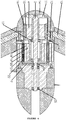
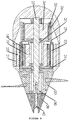
- FIGURES 1 and 4 show isometric and cross-sectional views, respectively, of one embodiment of the thruster design of the present invention.
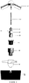
- FIGURES 2 and 3 are exploded isometric and plan views, respectively, of this embodiment of the thruster to show the constituent parts of the thruster.
- the thruster essentially comprises 8 parts (seven of which are arranged on a central shaft to form an elegant assembly as discussed below).
- Motor mounting system 1 comprises a water proof shell 11 with a rigid flange 12 that forms the watertight enclosure for the DC motor (shown generally at 3 ) and control electronics (not shown).
- the rigid flange 12 serves as a connection point for the struts 13 which secure the shroud 10.
- the motor mounting system 1 receives one end of the central shaft 2 , and includes water-tight ports (not shown) for receiving power and command input for the DC motor 3 .
- a spherical fairing 14 improves hydrodynamic performance.
- the central ground shaft 2 is a hard, rigid, corrosion resistant shaft with grooves for O-rings 24 , on which all stationary and rotating components are arranged. In particular, fixed components are held in place using keys (not shown), while rotating components utilize precision ball bearings 17 or bearing surfaces 25 . The components are fixed axially through the use of mechanical stops, set screws and retaining rings (not indicated).
- the use of a central shaft 2 ensures concentricity, minimizes losses due to eccentric bearing rotation and radial loads and therefore improves bearing life.
- the central shaft 2 has the added benefit of ease of assembly and maintenance.
- the DC motor 3 comprises a motor stator 4 that is custom wound to maximize efficiency throughout the desired range of output torques and rotational velocities, and motor rotor 5 comprised of motor magnets 15 that are fixed within ferromagnetic backing 16 , coupled to ground shaft 2 using precision ball bearings 17 to minimize power loss and constrained axially using a retaining ring (not indicated).
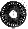
- the motor rotor 5 couples directly to the high-speed inner magnetic gear rotor 6 . More particularly, and with reference to Figure 5 , the magnetic gear system has three main components.
- the first component is a high-speed inner magnetic gear rotor 6 consisting of a number of alternating permanent magnetic pole pairs 18 . These are fixed to a ferromagnetic backing 19 in an effort to concentrate and contain magnetic flux.
- the second component is the low-speed outer magnetic gear rotor 8 which is similar to the high-speed inner magnetic gear rotor 6 , except it has a greater number of permanent magnetic pole pairs 20 fixed to a ferromagnetic backing 21 .
- the ratio of magnetic pole pairs 18 on high-speed inner magnetic gear rotor 6 to magnetic pole pairs 20 on low speed outer magnetic gear rotor 8 is what determines the gearing ratio. Between high-speed inner magnetic gear rotor 6 and low-speed outer magnetic gear rotor 8 lies the pole pieces 22 fixed within the pole piece fixture 23 .
- the pole pieces 22 modulate the flux between the high-speed inner magnetic gear rotor 6 and low-speed outer magnetic gear rotor 8 and establish a flux harmony, allowing the magnetic gear rotors to "mesh".
- the pole pieces 22 are composed of sintered magnetic composite or laminations to reduce eddy current losses.
- the pole piece fixture 23 is integral to the environmental barrier 7 and forms the stationary component of the magnetic gearing system.
- the environmental barrier 7 couples mechanically to the motor mounting system 1 and seals against the flange 12 and central shaft 2 through the use of static O-ring seals 24 , and houses the pole pieces 22 used to modulate magnetic flux and achieve the required flux harmony.
- the pole pieces 22 are encapsulated with potting compound to secure their placement and prevent corrosion.
- the low-speed magnetic gear rotor 8 is coupled to the central shaft 2 on bearing surfaces 25 , and comprises an alternating array of permanent magnet pairs 20 fixed to a ferromagnetic backing 21 to concentrate the magnetic flux.
- the permanent magnetic pole pairs 20 and ferromagnetic backing 21 in the low-speed outer magnetic gear rotor 8 are encapsulated using potting compound to protect from corrosive marine environment.
- the propeller 9 is a marine propeller, custom sized to provide maximum efficiency throughout the desired range of thrust and speeds.
- the propeller 9 is secured to the low speed magnetic gear rotor 8 using mechanical fasteners (not shown).
- a retaining ring (not indicated) axially constrains the low-speed magnetic gear rotor 8 , while bearing surfaces 25 constrain the low speed rotor 8 radially.
- the shroud 10 is a hydrodynamic foil that serves two main purposes. Firstly, it adds to the output thrust of the propeller 9 by creating a lifting surface, and minimizes the losses resulting from blade tip vortices. Secondly, it encloses and protects the propeller 9 from debris. In one embodiment, the shroud may also serve as the mounting point of the thruster. Propeller 9 is optimized for use within the shroud 10 .
- FIGURES 6 to 9 show another embodiment of the present invention.
- the thruster is powered by a brushless DC motor (shown generally at 28 ) which has an encapsulated stator 34 and motor magnets 35 fixed to a ferromagnetic backing 36 .
- the high-speed inner magnetic gear rotor 30 is fixed to motor rotor 29 .
- the low-speed outer magnetic gear rotor 32 couples to the propeller 33 .
- the intermediate magnetic gear-ring 31 houses the pole piece fixture 23 required for the operation of the magnetic gear system.
- All magnetic and ferrous components are encapsulated to prevent corrosion. All of the thruster components are arranged on a central shaft 27 forming an elegant assembly. Any non-rotating components are keyed to the shaft.
- the central shaft 27 allows the user to stack components allowing for multiple gear stages.
- the thruster essentially comprises 8 parts, seven of which are arranged on a central shaft 27 to form an elegant assembly as discussed below.
- Motor enclosure system 26 mainly serves as a protective covering for the DC motor 28 and holds one end of the central shaft 27 .
- Central shaft 27 is a hard, rigid, corrosion resistant shaft on which all stationary and rotating components are arranged. Fixed components are held using keys (not shown) and rotating components sit on precision ball bearings 37 or bearing surfaces 38 .
- the DC motor stator 34 is custom wound to maximize efficiency throughout the desired range of output torque and rotational velocity.
- the motor stator 34 and its windings (not shown) are encapsulated with a potting compound to protect them from the corrosive marine environment.
- the DC motor rotor 29 is lightweight and houses the motor magnets 35 and ferromagnetic backing 36 , and transmits the rotational power of the motor.
- the motor magnets 35 and ferromagnetic backing 36 are encapsulated with a potting compound to protect them from the corrosive marine environment.
- the motor rotor 29 is coupled to the central shaft 27 using precision ball bearings 37 to minimize power loss.
- the motor rotor 29 is fixed directly to the high-speed inner magnetic gear rotor 30 . More particularly, and once again with reference to Figure 5 , the magnetic gear system has three main components.
- the first component is a high-speed inner magnetic gear rotor 30 consisting of a number of alternating permanent magnetic pole pairs 18 . These are fixed to a ferromagnetic backing 19 in an effort to concentrate and contain magnetic flux.
- the second component is the low-speed outer magnetic gear rotor 32 which is similar to the high-speed inner magnetic gear rotor 30 , except it has a greater number of permanent magnetic pole pairs 20 fixed to a ferromagnetic backing 21 .
- the ratio of magnetic pole pairs 18 on high-speed inner magnetic gear rotor 30 to magnetic pole pairs 20 on low-speed outer magnetic gear rotor 32 is what determines the gearing ratio.
- Between high-speed inner magnetic gear rotor 30 and low-speed outer magnetic gear rotor 32 are the pole pieces 22 fixed within a pole piece fixture 23 .
- the pole pieces 22 modulate the flux between the high-speed inner magnetic gear rotor 30 and low-speed outer magnetic gear rotor 32 and establish a flux harmony, allowing the magnetic gear rotors to "mesh".
- the pole pieces 22 are composed of sintered magnetic composite or laminations to reduce eddy current losses.
- the pole piece fixture 23 is integral to the intermediate magnetic gear-ring 31 and forms the stationary component of the magnetic gearing system. Pole pieces 22 are encapsulated with potting material to secure their placement and prevent corrosion.
- the intermediate magnetic gear-ring 31 is keyed to the central shaft 27 .
- the low-speed outer magnetic gear rotor 32 is coupled to the central shaft 27 through the use of bearing surfaces 38 .
- the permanent magnetic pole pairs 20 and ferromagnetic backing 21 are encapsulated using potting compound to protect them from the corrosive marine environment.
- the propeller 33 is a marine propeller that is custom sized to provide maximum efficiency throughout the desired range of thrust and speeds.
- the low-speed outer magnetic gear rotor 32 is secured to the central shaft 27 using an end cap 39 and retaining screw 40 .
- the efficiency boost from a shroud can often be minor, and if the thruster is not expected to experience any debris a shroud may not be considered necessary as it adds to the overall size and weight of the thruster.
- an exterior shell could be used.
- an interior rotor brushless motor would be coupled to the high speed inner magnetic gear rotor consisting of alternating permanent magnetic pole pairs 18 and ferromagnetic ring 19 .
- the outer permanent magnetic pole pairs 20 and ferromagnetic backing 21 would be held stationary and the intermediate pole piece fixture 23 would serve as the low-speed output and would couple to the propeller.
- ROVs benefit from increased power density as a result of the increase in the thrust to weight ratio of vehicles designed in accordance with the present invention, which leads to improved responsiveness.
- This increase in responsiveness can translate to increased operator performance and can decrease task completion times, which makes the improved ROVs attractive for use as inspection, intervention and survey class vehicles.
- AUVs designed in accordance with the present invention benefit from increased propulsive efficiency.
- an AUVs mission endurance is directly proportional to the amount of power used by all the systems on board.
- Optimal mission plans typically try to balance the power used by the propulsion system and the payload sensors in an attempt to traverse the maximum distance with the payload sensors in use.
Landscapes
- Engineering & Computer Science (AREA)
- Power Engineering (AREA)
- Mechanical Engineering (AREA)
- Chemical & Material Sciences (AREA)
- Combustion & Propulsion (AREA)
- Ocean & Marine Engineering (AREA)
- Aviation & Aerospace Engineering (AREA)
- Connection Of Motors, Electrical Generators, Mechanical Devices, And The Like (AREA)
Description
- The present invention relates to an electric drive, and more particularly to a magnetically geared electric drive. Specifically, the present invention relates to an encapsulated magnetically geared brushless electric drive arranged around a central shaft or external shell.
- Autonomous underwater vehicle propulsion systems typically use electric motors with mechanical gearing to reduce the rotational speed, such that it is well matched to the peak operating point of a propeller [see, for e.g., B. Claus, R. Bachmayer, and C. D. Williams, "Development of an auxiliary propulsion module for an autonomous underwater glider," Proceedings of the Institution of Mechanical Engineers, Part M: Journal of Engineering for the Maritime Environment, vol. 224, no. 4, pp. 255-266, 2010. [Online]. Available: http://pim.sagepub.com/content/224/4/255.abstract; and M. E. Furlong, D. Paxton, and P. Stevenson, "Autosub long range: A long range deep diving AUV for ocean monitoring," in Autonomous Underwater Vehicles (AUV), 2012 IEEE/OES, sept. 2012, pp. 1 -7]. Alternative designs use a custom built direct drive brushless motor for reliability reasons but unfortunately they have higher losses and are significantly larger than their geared counterparts [see, for e.g., J. Bellingham, Y. Zhang, J. Kerwin, J. Erikson, B. Hobson, B. Kieft, M. Godin, R. McEwen, T. Hoover, J. Paul, A. Hamilton, J. Franklin, and A. Banka, "Efficient propulsion for the Tethys long-range autonomous underwater vehicle," in Autonomous Underwater Vehicles (AUV), 2010 IEEE/OES, sept. 2010, pp. 1 -7]. A magnetically coupled gearing system, however, has several significant advantages compared to classical mechanical gear reduction methods. For one, the lack of physical contact between rotating parts - other than engineered bearing surfaces - eliminates excessive mechanical wear and greatly reduces the effect of load disturbances. In addition, inherent overload protection resulting from the physical isolation of input and output rotors, prevents premature failure of components in the event of a sudden torque application. The lack of mechanical contact also leads to a reduction in vibrations and acoustic noise. Furthermore, a magnetic gear can eliminate the need for rotary shaft seals by isolating the motor and drive electronics from the environment with a barrier in the air gap. As a result, one can appreciate that a magnetic gear system is well suited for underwater vehicle propulsion systems where long term, maintenance-free application is an asset. Magnetic gearing itself has been the subject of fascination for well over one hundred years with patents on the subject first showing up as early as 1913 [see, for e.g., A. H. Neuland, "Apparatus for transmitting power,"
U.S. Patent 1171351, 1916 ]. These early gears, however, were often complex machines with low torque density and did not see wide spread use [see, for e.g., H. T. Faus, "Magnet gearing,"U.S. Patent 2243555, 1941 ; K. Tsurumoto and S. Kikuchi, "A new magnetic gear using permanent magnet," Magnetics, IEEE Transactions on, vol. 23, no. 5, pp. 3622 - 3624, sep 1987; and S. Kikuchi and K. Tsurumoto, "Design and characteristics of a new magnetic worm gear using permanent magnet," Magnetics, IEEE Transactions on, vol. 29, no. 6, pp. 2923 -2925, nov 1993]. More recently, in 2001 Atallah et al. presented an initial concept for a high torque density magnetic gear comprising three rotors, namely a high speed, low speed and modulating rotor containing ferromagnetic pole pieces [see K. Atallah and D. Howe, "A novel high-performance magnetic gear," Magnetics, IEEE Transactions on, vol. 37, no. 4, pp. 2844 - 2846, jul 2001]. A follow up paper presented the experimental validation in which torque densities of up to 100 kNm/m3 with up to 97% efficiency and gear ratios of 2-12 were demonstrated [see K. Atallah, S. Calverley, and D. Howe, "Design, analysis and realisation of a high-performance magnetic gear," Electric Power Applications, IEEE Proceedings -, vol. 151, no. 2, pp. 135 - 143, mar 2004].US8512084 B1 provides a thruster. A magnetic core unit rotates. Several magnetic intermediate units are arranged around the magnetic core unit. Each magnetic intermediate unit rotates about its own central axis. A cover body is placed outside the magnetic intermediate units.TW201240879 A US2011/127864 A1 provide other known arrangements. - What is needed, however, is a magnetically geared electric drive having a design that is intended and well suited for reliable, long term application in an underwater vehicle where efficiency of energy transmission is useful.
- In accordance with a first aspect of the invention, an apparatus comprising the features of appended
claim 1 is provided. In accordance with a second aspect of the invention, an apparatus comprising the features of appendedclaim 7 is provided. The dependent claims provide further details of embodiments of the invention. - The present invention provides an environmentally sealed, magnetically geared electric drive that combines several distinct technical components into a single compact solution to be used for underwater vehicles, such as remotely operated vehicles (ROV), autonomous underwater vehicles (AUV) and human occupied underwater vehicles (HOV). The device consists essentially of a motor stator, motor rotor, high-speed inner magnetic gear rotor, encapsulated pole pieces, and encapsulated low-speed outer magnetic gear rotor, all arranged around a central shaft. The combination of these elements into a single underwater electric drive device provides a low maintenance,
reliable, and efficient configuration for underwater drive applications. An advantage of this system is the simplified arrangement around a central shaft which allows for multiple stages of gearing. Another advantage of this system is that by combining encapsulation technology with magnetic gear technology, the entire device can be made smaller and lighter, and thereby improving the power density of the device. -
-
FIGURE 1 is an isometric view of one embodiment of the thruster design of the present invention; -
FIGURE 2 is an exploded isometric view of the embodiment of the thruster design shown inFigure 1 ; -
FIGURE 3 is an exploded plan view of the embodiment of the thruster design shown inFigure 1 ; -
FIGURE 4 is a cross-sectional view of the embodiment of the thruster design shown inFigure 1 ; -
FIGURE 5 is a schematic of an embodiment of the magnetic gear used in the thruster design of the present invention; -
FIGURE 6 is an isometric view of a second embodiment of the thruster design of the present invention; -
FIGURE 7 is an exploded isometric view of the embodiment of the thruster design shown inFigure 6 ; -
FIGURE 8 is an exploded plan view of the embodiment of the thruster design shown inFigure 6 ; and -
FIGURE 9 is a cross-sectional view of the embodiment of the thruster design shown inFigure 6 ; - The propulsion system design of the present invention is intended to increase the overall efficiency and reliability of current marine propulsion systems, and also has general ease of assembly and maintenance. It is powered by an environmentally isolated brushless DC motor driven by a high efficiency motor controller. Environmental isolation is made possible through the use of an environmental barrier which doubles as a portion of the magnetic gearing system or through encapsulation. Sensitive magnetic and ferrous components which remain outside of the barrier are encapsulated for environmental protection. All of the thruster components are arranged on a central shaft serving as a mechanical ground, thereby forming an elegant assembly. A static O-ring seal within the environmental barrier allows passage of the ground shaft between dry and wet sections. Thrust output is maximized through the use of a purpose-built propeller and shroud along with hydro-dynamically faired struts and nosecone.
- While magnetic gearing and encapsulated motors are known concepts, combining them and arranging them around a central shaft in the manner disclosed herein is novel, and provides several key advantages that are particularly useful and applicable to the marine propulsion technology sector. First of all, magnetic gears themselves have been shown to be more efficient than their mechanical counterparts with demonstrated efficiencies often above 95%. An arrangement around a central shaft as disclosed herein allows for the stacking of magnetic gear elements to form a multistage magnetic gear, thereby increasing the gearing ratio dramatically. Secondly, marine propulsors achieve peak performance at relatively low rotational speeds and high torques, while ungeared electric motors generally operate at higher speeds and lower torques. Therefore, the solution of the present invention, which decreases the speed of electric motors and increases the torque while maintaining a high efficiency energy conversion, is desirable in the marine propulsion technology sector. Additionally, by encapsulating the parts as disclosed herein, there is reduced need for pressure chambers or shaft seals, and the power density and reliability of the device is accordingly increased. Specifically, because the magnetic gearing system has no sliding contact - other than from engineered bearing surfaces - there are reduced frictional losses, leading to a boost in efficiency. This also means they do not wear, leading to longer mean time between failures than mechanical gears. In addition, in the event that one of the rotors becomes jammed, the magnetic gear will ratchet or slip, preventing damage to other system components. Reduced acoustic noise is an additional feature of the magnetic gear discussed herein.
- The invention of the present disclosure is more fully explained with reference to the Figures and the description that follows.
FIGURES 1 and4 show isometric and cross-sectional views, respectively, of one embodiment of the thruster design of the present invention.FIGURES 2 and3 are exploded isometric and plan views, respectively, of this embodiment of the thruster to show the constituent parts of the thruster. With reference toFigures 2 and3 , the thruster essentially comprises 8 parts (seven of which are arranged on a central shaft to form an elegant assembly as discussed below).Motor mounting system 1 comprises a waterproof shell 11 with arigid flange 12 that forms the watertight enclosure for the DC motor (shown generally at 3) and control electronics (not shown). Therigid flange 12 serves as a connection point for thestruts 13 which secure theshroud 10. Themotor mounting system 1 receives one end of thecentral shaft 2, and includes water-tight ports (not shown) for receiving power and command input for theDC motor 3. Aspherical fairing 14 improves hydrodynamic performance. Thecentral ground shaft 2 is a hard, rigid, corrosion resistant shaft with grooves for O-rings 24, on which all stationary and rotating components are arranged. In particular, fixed components are held in place using keys (not shown), while rotating components utilizeprecision ball bearings 17 or bearing surfaces 25. The components are fixed axially through the use of mechanical stops, set screws and retaining rings (not indicated). The use of acentral shaft 2 ensures concentricity, minimizes losses due to eccentric bearing rotation and radial loads and therefore improves bearing life. Thecentral shaft 2 has the added benefit of ease of assembly and maintenance. TheDC motor 3 comprises amotor stator 4 that is custom wound to maximize efficiency throughout the desired range of output torques and rotational velocities, andmotor rotor 5 comprised ofmotor magnets 15 that are fixed withinferromagnetic backing 16, coupled toground shaft 2 usingprecision ball bearings 17 to minimize power loss and constrained axially using a retaining ring (not indicated). Themotor rotor 5 couples directly to the high-speed innermagnetic gear rotor 6. More particularly, and with reference toFigure 5 , the magnetic gear system has three main components. The first component is a high-speed innermagnetic gear rotor 6 consisting of a number of alternating permanent magnetic pole pairs 18. These are fixed to aferromagnetic backing 19 in an effort to concentrate and contain magnetic flux. The second component is the low-speed outermagnetic gear rotor 8 which is similar to the high-speed innermagnetic gear rotor 6, except it has a greater number of permanent magnetic pole pairs 20 fixed to aferromagnetic backing 21. The ratio of magnetic pole pairs 18 on high-speed innermagnetic gear rotor 6 to magnetic pole pairs 20 on low speed outermagnetic gear rotor 8 is what determines the gearing ratio. Between high-speed innermagnetic gear rotor 6 and low-speed outermagnetic gear rotor 8 lies thepole pieces 22 fixed within thepole piece fixture 23. Thepole pieces 22 modulate the flux between the high-speed innermagnetic gear rotor 6 and low-speed outermagnetic gear rotor 8 and establish a flux harmony, allowing the magnetic gear rotors to "mesh". Thepole pieces 22 are composed of sintered magnetic composite or laminations to reduce eddy current losses. With reference toFigures 2 ,3 and4 , thepole piece fixture 23 is integral to theenvironmental barrier 7 and forms the stationary component of the magnetic gearing system. Theenvironmental barrier 7 couples mechanically to themotor mounting system 1 and seals against theflange 12 andcentral shaft 2 through the use of static O-ring seals 24, and houses thepole pieces 22 used to modulate magnetic flux and achieve the required flux harmony. Thepole pieces 22 are encapsulated with potting compound to secure their placement and prevent corrosion. The low-speedmagnetic gear rotor 8 is coupled to thecentral shaft 2 on bearingsurfaces 25, and comprises an alternating array of permanent magnet pairs 20 fixed to aferromagnetic backing 21 to concentrate the magnetic flux. The permanent magnetic pole pairs 20 andferromagnetic backing 21 in the low-speed outermagnetic gear rotor 8 are encapsulated using potting compound to protect from corrosive marine environment. Thepropeller 9 is a marine propeller, custom sized to provide maximum efficiency throughout the desired range of thrust and speeds. Thepropeller 9 is secured to the low speedmagnetic gear rotor 8 using mechanical fasteners (not shown). A retaining ring (not indicated) axially constrains the low-speedmagnetic gear rotor 8, while bearingsurfaces 25 constrain thelow speed rotor 8 radially. Theshroud 10 is a hydrodynamic foil that serves two main purposes. Firstly, it adds to the output thrust of thepropeller 9 by creating a lifting surface, and minimizes the losses resulting from blade tip vortices. Secondly, it encloses and protects thepropeller 9 from debris. In one embodiment, the shroud may also serve as the mounting point of the thruster.Propeller 9 is optimized for use within theshroud 10. -
FIGURES 6 to 9 show another embodiment of the present invention. As seen inFIGURES 6 and9 which show isometric and cross-sectional views, respectively, the use of additional encapsulation in this embodiment further increases simplicity and allows for the "stacking" of components without the use of barriers. In this embodiment, the thruster is powered by a brushless DC motor (shown generally at 28) which has an encapsulatedstator 34 andmotor magnets 35 fixed to aferromagnetic backing 36. The high-speed innermagnetic gear rotor 30 is fixed tomotor rotor 29. The low-speed outermagnetic gear rotor 32 couples to thepropeller 33. The intermediate magnetic gear-ring 31 houses thepole piece fixture 23 required for the operation of the magnetic gear system. All magnetic and ferrous components are encapsulated to prevent corrosion. All of the thruster components are arranged on acentral shaft 27 forming an elegant assembly. Any non-rotating components are keyed to the shaft. Thecentral shaft 27 allows the user to stack components allowing for multiple gear stages. - This embodiment of the present invention is more fully explained with reference to
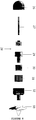
Figures 7 ,8 and9 , which show exploded isometric, plan view and cross sectional views of this alternative embodiment of the thruster to show the constituent parts of the thruster. With particular reference toFigures 7 and8 , the thruster essentially comprises 8 parts, seven of which are arranged on acentral shaft 27 to form an elegant assembly as discussed below.Motor enclosure system 26 mainly serves as a protective covering for theDC motor 28 and holds one end of thecentral shaft 27.Central shaft 27 is a hard, rigid, corrosion resistant shaft on which all stationary and rotating components are arranged. Fixed components are held using keys (not shown) and rotating components sit onprecision ball bearings 37 or bearing surfaces 38. Using acentral shaft 27 for all components ensures concentricity and minimizes losses due to eccentric bearing rotation and radial loads. Thecentral shaft 27 has the added benefit of ease of assembly and maintenance. By extending thecentral shaft 27, additional gear stages can be stacked. With reference toFigures 7 to 9 , theDC motor stator 34 is custom wound to maximize efficiency throughout the desired range of output torque and rotational velocity. Themotor stator 34 and its windings (not shown) are encapsulated with a potting compound to protect them from the corrosive marine environment. TheDC motor rotor 29 is lightweight and houses themotor magnets 35 andferromagnetic backing 36, and transmits the rotational power of the motor. Themotor magnets 35 andferromagnetic backing 36 are encapsulated with a potting compound to protect them from the corrosive marine environment. Themotor rotor 29 is coupled to thecentral shaft 27 usingprecision ball bearings 37 to minimize power loss. Themotor rotor 29 is fixed directly to the high-speed innermagnetic gear rotor 30. More particularly, and once again with reference toFigure 5 , the magnetic gear system has three main components. The first component is a high-speed innermagnetic gear rotor 30 consisting of a number of alternating permanent magnetic pole pairs 18. These are fixed to aferromagnetic backing 19 in an effort to concentrate and contain magnetic flux. The second component is the low-speed outermagnetic gear rotor 32 which is similar to the high-speed innermagnetic gear rotor 30, except it has a greater number of permanent magnetic pole pairs 20 fixed to aferromagnetic backing 21. The ratio of magnetic pole pairs 18 on high-speed innermagnetic gear rotor 30 to magnetic pole pairs 20 on low-speed outermagnetic gear rotor 32 is what determines the gearing ratio. Between high-speed innermagnetic gear rotor 30 and low-speed outermagnetic gear rotor 32 are thepole pieces 22 fixed within apole piece fixture 23. Thepole pieces 22 modulate the flux between the high-speed innermagnetic gear rotor 30 and low-speed outermagnetic gear rotor 32 and establish a flux harmony, allowing the magnetic gear rotors to "mesh". Thepole pieces 22 are composed of sintered magnetic composite or laminations to reduce eddy current losses. With reference toFigures 7 to 9 , thepole piece fixture 23 is integral to the intermediate magnetic gear-ring 31 and forms the stationary component of the magnetic gearing system.Pole pieces 22 are encapsulated with potting material to secure their placement and prevent corrosion. The intermediate magnetic gear-ring 31 is keyed to thecentral shaft 27. The low-speed outermagnetic gear rotor 32 is coupled to thecentral shaft 27 through the use of bearing surfaces 38. The permanent magnetic pole pairs 20 andferromagnetic backing 21 are encapsulated using potting compound to protect them from the corrosive marine environment. Thepropeller 33 is a marine propeller that is custom sized to provide maximum efficiency throughout the desired range of thrust and speeds. The low-speed outermagnetic gear rotor 32 is secured to thecentral shaft 27 using anend cap 39 and retainingscrew 40. - In addition to the foregoing, there are a number of additional configurations and modifications that can be made to the aforementioned thruster configuration embodiments described above that could potentially result in a performance boost, increased reliability, or ease of fabrication / assembly / maintenance. In particular, regarding the
pole pieces 22, because they are held in a plastic fixture, it could be beneficial to permanently mold them into the fixture rather than have them encapsulated. This would remove the need for an additional potting process and would ensure that thepole pieces 22 never come loose from their housing. In addition, the use of ashroud 8 with an underwater thruster is not a requirement. In this respect, the efficiency boost from a shroud can often be minor, and if the thruster is not expected to experience any debris a shroud may not be considered necessary as it adds to the overall size and weight of the thruster. Furthermore, in addition to using a central shaft as a mechanical ground, an exterior shell could be used. In this configuration, an interior rotor brushless motor would be coupled to the high speed inner magnetic gear rotor consisting of alternating permanent magnetic pole pairs 18 andferromagnetic ring 19. The outer permanent magnetic pole pairs 20 andferromagnetic backing 21 would be held stationary and the intermediatepole piece fixture 23 would serve as the low-speed output and would couple to the propeller. - ROVs benefit from increased power density as a result of the increase in the thrust to weight ratio of vehicles designed in accordance with the present invention, which leads to improved responsiveness. This increase in responsiveness can translate to increased operator performance and can decrease task completion times, which makes the improved ROVs attractive for use as inspection, intervention and survey class vehicles. Similarly, AUVs designed in accordance with the present invention benefit from increased propulsive efficiency. In particular, since AUVs must be self-contained with respect to their energy (usually in the form of batteries), an AUVs mission endurance is directly proportional to the amount of power used by all the systems on board. Optimal mission plans typically try to balance the power used by the propulsion system and the payload sensors in an attempt to traverse the maximum distance with the payload sensors in use. By increasing the propulsive efficiency, the thrust to the vehicle is increased for the same payload specifications, thereby increasing the overall speed with which an AUV completes a mission. Similarly, by maintaining the same speed for the same payload, the endurance of the AUV is extended, thereby increasing the amount of potential area covered by a survey. In view of the foregoing, operators of ROV and AUV systems comprising the new propulsion systems of the present invention can see increased efficiencies and cost-savings.
- Although specific embodiments of the invention have been described, it will be apparent to one skilled in the art that variations and modifications to the embodiments may be made within the scope of the following claims.
Claims (10)
- An encapsulated magnetically geared brushless electric drive comprising the following components:a motor mounting system (1) coupled to a first distal end of a central shaft (2), said mounting system comprising a water proof shell with a rigid flange (12) connected to struts (13), and including water-tight ports for receiving power and command input;a DC motor (3) coupled to the motor mounting system (1), comprising a motor stator (4) fixed to the central shaft (2) and motor magnets fixed within a motor rotor (5) which is coupled to the central shaft using ball bearings (17);a high-speed inner magnetic gear rotor (6) coupled to the motor rotor (5) comprising an alternating array of magnets fixed to a ferromagnetic backing (16);an environmental barrier (7) coupled to the motor mounting system (1) that seals against the motor mounting system (1) and central shaft (2) by means of O-ring seals (24), and that further houses pole pieces (22) to modulate magnetic flux;a low-speed outer magnetic gear rotor (8) coupled to a second distal end of the central shaft (2) comprising an alternating array of magnets fixed to a ferromagnetic backing (21);a propeller (9) coupled to the low-speed outer magnetic gear rotor (8); anda shroud (10) coupled to the struts (13) of the motor mounting system (1),wherein each of said components are arranged axially around the central shaft (2) using spacers and mechanical stops, and wherein said components are held in place by means of one of keys or bearings (17).
- The encapsulated magnetically geared brushless electric drive of claim 1, wherein the low-speed outer magnetic gear rotor (8) is constrained radially by use of bearing surfaces (25).
- The encapsulated magnetically geared brushless electric drive of claim 1 or claim 2, wherein:each of said components is constrained axially by use of the spacers and mechanical stops; andnon-rotating components are keyed to the central shaft (2).
- A remotely operated vehicle (ROV) comprising the encapsulated magnetically geared brushless electric drive of claim 1.
- An autonomous underwater vehicle (AUV) comprising the encapsulated magnetically geared brushless electric drive of claim 1.
- A human occupied underwater vehicle (HOV) comprising the encapsulated magnetically geared brushless electric drive of claim 1.
- An encapsulated magnetically geared brushless electric drive comprising the following components:a motor enclosure system that is fixed to a first distal end of a central shaft (27);a DC motor stator (34) fixed to the motor enclosure system, said stator (34) encapsulated with potting compound;a DC motor rotor (29) coupled to the DC motor stator (34), said motor rotor (29) housing motor magnets, said motor magnets encapsulated with potting compound;a high-speed inner magnetic gear rotor (30) coupled to the motor rotor (29) comprising an alternating array of magnets (18) fixed to a ferromagnetic backing (19), said high-speed inner magnetic gear rotor (30) encapsulated with potting compound;an intermediate magnetic gear-ring (31) coupled to the central shaft and housing pole pieces, wherein said pole pieces are encapsulated with potting compound and contained within a pole piece fixture (23);a low-speed outer magnetic gear rotor (32) coupled to the central shaft (27) comprising an alternating array of magnets (20) fixed to a ferromagnetic backing (21), said low-speed outer magnetic gear rotor (32) encapsulated with potting compound; anda propeller (33) coupled to the low-speed outer magnetic gear rotor,wherein each of said components are arranged axially around the central shaft (27) using spacers and mechanical stops, and wherein said components are held in place by means of one of keys or bearings (37).
- A remotely operated vehicle (ROV) comprising the encapsulated magnetically geared brushless electric drive of claim 7.
- An autonomous underwater vehicle (AUV) comprising the encapsulated magnetically geared brushless electric drive of claim 7.
- A human occupied underwater vehicle (HOV) comprising the encapsulated magnetically geared brushless electric drive of claim 7.
Applications Claiming Priority (2)
| Application Number | Priority Date | Filing Date | Title |
|---|---|---|---|
| US201461936656P | 2014-02-06 | 2014-02-06 | |
| PCT/CA2015/000070 WO2015117231A1 (en) | 2014-02-06 | 2015-02-06 | A magnetically geared electric drive |
Publications (3)
| Publication Number | Publication Date |
|---|---|
| EP3102484A1 EP3102484A1 (en) | 2016-12-14 |
| EP3102484A4 EP3102484A4 (en) | 2017-11-22 |
| EP3102484B1 true EP3102484B1 (en) | 2019-05-01 |
Family
ID=53777092
Family Applications (1)
| Application Number | Title | Priority Date | Filing Date |
|---|---|---|---|
| EP15746809.1A Active EP3102484B1 (en) | 2014-02-06 | 2015-02-06 | A magnetically geared electric drive |
Country Status (5)
| Country | Link |
|---|---|
| US (1) | US9908603B2 (en) |
| EP (1) | EP3102484B1 (en) |
| CN (1) | CN106061835B (en) |
| CA (1) | CA2938534C (en) |
| WO (1) | WO2015117231A1 (en) |
Families Citing this family (25)
| Publication number | Priority date | Publication date | Assignee | Title |
|---|---|---|---|---|
| US20180229825A1 (en) * | 2014-05-01 | 2018-08-16 | Blue Robotics Inc. | Submersible electric thruster |
| US20160281679A1 (en) * | 2015-01-29 | 2016-09-29 | Donald Wichers | Fluid driven electric power generation system |
| WO2017062654A1 (en) * | 2015-10-09 | 2017-04-13 | The Texas A&M University System | Method and apparatus for compact axial flux magnetically geared machines |
| CN105235844A (en) * | 2015-11-17 | 2016-01-13 | 天津深之蓝海洋设备科技有限公司 | Magnetic coupling underwater propeller |
| CN206968956U (en) | 2017-05-05 | 2018-02-06 | 天津深之蓝海洋设备科技有限公司 | Underwater propeller and submersible |
| FR3068330B1 (en) * | 2017-06-29 | 2020-12-04 | Maarten Mostert | HYDRAULIC PROPULSION DEVICE FORMING PROPELLER PUMP AND SHIP EQUIPPED WITH SUCH A DEVICE |
| CN107792322A (en) * | 2017-10-24 | 2018-03-13 | 深圳乐智机器人有限公司 | Magnetic coupling bionic coatings device and underwater robot |
| CN108173389A (en) * | 2018-02-09 | 2018-06-15 | 周隆祥 | A kind of underwater propeller |
| DE102018110151A1 (en) * | 2018-04-26 | 2019-10-31 | Linz Center Of Mechatronics Gmbh | Electric machine with electric motor and magnetic gear |
| CN108394538A (en) * | 2018-04-28 | 2018-08-14 | 巨浪创新(深圳)科技有限公司 | A kind of integrated small underwater robot propeller |
| CN108639298A (en) * | 2018-07-16 | 2018-10-12 | 常州高尔登科技有限公司 | A kind of direct drive electric shipboard |
| CN109292063B (en) * | 2018-11-23 | 2023-11-03 | 上海晟钧节能科技有限公司 | Power device for deep sea diving device |
| CN109474109B (en) * | 2019-01-11 | 2024-03-29 | 苏州优德通力科技有限公司 | Sealed external rotor motor structure |
| CN111699611B (en) * | 2019-02-14 | 2023-03-14 | 苏州微孚智能科技有限公司 | Full-immersion type underwater propeller and electric floating plate |
| CN110395377A (en) * | 2019-08-02 | 2019-11-01 | 武汉札古海洋科技有限公司 | an underwater thruster |
| JP7600564B2 (en) * | 2020-08-24 | 2024-12-17 | ニデック株式会社 | Motors and Drive Units |
| CN113501115A (en) * | 2021-07-30 | 2021-10-15 | 上海交通大学 | Underwater vehicle magnetic gear coupling propulsion system, working method and underwater vehicle |
| CN113978669A (en) * | 2021-11-07 | 2022-01-28 | 天津大学 | Autonomous underwater vehicle propulsion device based on magnetic gear composite motor |
| CN114013619B (en) * | 2021-11-10 | 2022-09-27 | 国家深海基地管理中心 | Deep sea magnetic coupling isolation oil compensation propeller |
| CN114337187A (en) * | 2021-12-31 | 2022-04-12 | 广东美的白色家电技术创新中心有限公司 | In-wheel motor and vehicle |
| CN116142437A (en) * | 2022-12-28 | 2023-05-23 | 天津大学 | A variable magnetic force magnetic coupling propulsion device for an underwater vehicle |
| US12117094B1 (en) | 2023-05-01 | 2024-10-15 | Magdrive Technologies, Inc. | Magnetically actuated pipe valve with torque-limiting clutch and position indication |
| US12460738B2 (en) | 2023-05-01 | 2025-11-04 | Magdrive Technologies, Inc. | Magnetically actuated pipe valve with torque-limiting clutch and position indication |
| JP2025028560A (en) * | 2023-08-18 | 2025-03-03 | 三菱重工業株式会社 | MOBILE BODY CONTROL DEVICE, MOBILE BODY ... CONTROL METHOD, AND PROGRAM |
| CN119210086B (en) * | 2024-11-29 | 2025-04-11 | 华东交通大学 | Monotone magnetic ring double modulation type magnetic gear and wheel hub motor for new energy vehicles |
Family Cites Families (15)
| Publication number | Priority date | Publication date | Assignee | Title |
|---|---|---|---|---|
| US3914629A (en) * | 1974-12-13 | 1975-10-21 | William P Gardiner | Centerless brushless DC motor |
| US5306183A (en) * | 1993-02-25 | 1994-04-26 | Harbor Branch Oceanographic Institute Inc. | Propulsion systems for submarine vessels |
| JPH1066293A (en) * | 1996-08-12 | 1998-03-06 | Ebara Corp | Canned motor |
| JP4631382B2 (en) * | 2004-10-04 | 2011-02-16 | 日本電産株式会社 | Brushless motor |
| US8358044B2 (en) * | 2006-02-14 | 2013-01-22 | General Electric Company | Electric machine apparatus with integrated, high torque density magnetic gearing |
| JP2007336699A (en) * | 2006-06-15 | 2007-12-27 | Sony Corp | DC motor and DC motor mounting structure |
| GB2468888B (en) * | 2009-03-26 | 2013-11-06 | Magnomatics Ltd | Marine propulsion device with an electrical machine having integral magnetic gearing |
| EP2330725B1 (en) * | 2009-12-02 | 2014-02-26 | Grundfos Management A/S | Flow generation unit |
| US8299669B2 (en) * | 2010-10-18 | 2012-10-30 | Hamilton Sundstrand Corporation | Rim driven thruster having transverse flux motor |
| TWI402201B (en) * | 2011-04-01 | 2013-07-21 | Chieng Ming Ind Co Ltd | Underwater propeller |
| EP2594477A1 (en) * | 2011-11-18 | 2013-05-22 | Hamilton Sundstrand Corporation | Rim driven thruster having transverse flux motor |
| DE102012008802A1 (en) * | 2012-05-07 | 2013-11-07 | Weier Antriebe und Energietechnik GmbH | Electrical machine has rotor and stator provided on adjacent annular surfaces and acted upon by surrounding water, and metallic casing whose adjacent annular surfaces are connected with respective sheet stack ring by elastomer |
| US8512084B1 (en) * | 2012-05-21 | 2013-08-20 | Nai-Jen Chang | Underwater thruster |
| CN202923877U (en) * | 2012-09-21 | 2013-05-08 | 哈尔滨工程大学 | Small-size underwater magnetic coupling propeller device |
| CN203246580U (en) * | 2013-03-21 | 2013-10-23 | 国家海洋技术中心 | Deep-sea high-temperature mini underwater propeller propelling device adopting magnetic transmission and pressure compensation |
-
2015
- 2015-02-06 WO PCT/CA2015/000070 patent/WO2015117231A1/en not_active Ceased
- 2015-02-06 CA CA2938534A patent/CA2938534C/en not_active Expired - Fee Related
- 2015-02-06 EP EP15746809.1A patent/EP3102484B1/en active Active
- 2015-02-06 CN CN201580012312.7A patent/CN106061835B/en not_active Expired - Fee Related
- 2015-02-06 US US15/117,028 patent/US9908603B2/en not_active Expired - Fee Related
Non-Patent Citations (1)
| Title |
|---|
| None * |
Also Published As
| Publication number | Publication date |
|---|---|
| CA2938534A1 (en) | 2015-08-13 |
| US9908603B2 (en) | 2018-03-06 |
| CA2938534C (en) | 2017-10-24 |
| US20170166288A1 (en) | 2017-06-15 |
| CN106061835A (en) | 2016-10-26 |
| CN106061835B (en) | 2018-06-15 |
| WO2015117231A1 (en) | 2015-08-13 |
| EP3102484A1 (en) | 2016-12-14 |
| EP3102484A4 (en) | 2017-11-22 |
Similar Documents
| Publication | Publication Date | Title |
|---|---|---|
| CA2938534C (en) | A magnetically geared electric drive | |
| US5306183A (en) | Propulsion systems for submarine vessels | |
| Yan et al. | A review of progress and applications of ship shaft-less rim-driven thrusters | |
| US12291319B2 (en) | Marine vehicle with submersible electric thruster | |
| EP3218259B1 (en) | Underwater propelling device for underwater vehicle | |
| US7385303B2 (en) | Integrated fluid power conversion system | |
| CN103026600B (en) | Electric drives for aircraft | |
| CN103818535B (en) | Integrate motor propelling unit | |
| CN112737255B (en) | Disc type double rotor contra-rotating motor and aircraft | |
| WO2015200557A1 (en) | Improved-efficiency submersible thruster | |
| EP2594477A1 (en) | Rim driven thruster having transverse flux motor | |
| US20230113435A1 (en) | Submerged electrical machines | |
| JP2022548201A (en) | Electric motor with intrinsic cooling system | |
| CN113955063A (en) | A rim thruster driven by an ironless permanent magnet motor | |
| CN113978669A (en) | Autonomous underwater vehicle propulsion device based on magnetic gear composite motor | |
| JPS626892A (en) | Water jet generating device | |
| CN112406434A (en) | Electric water-air dual-purpose propeller | |
| RU2670364C1 (en) | Propulsion-steering column | |
| Holt et al. | High efficiency, counter-rotating ring thruster for underwater vehicles | |
| US20070046131A1 (en) | Boat drive | |
| CN109229320A (en) | A kind of underwater propeller | |
| RU2583125C1 (en) | Marine propulsion installation | |
| CN220010062U (en) | Propeller driven by shaftless radial flux motor | |
| CN119253962B (en) | A shaftless rim propeller with axial magnetic flux | |
| CN216468387U (en) | An autonomous underwater vehicle propulsion device based on magnetic gear composite motor |
Legal Events
| Date | Code | Title | Description |
|---|---|---|---|
| PUAI | Public reference made under article 153(3) epc to a published international application that has entered the european phase |
Free format text: ORIGINAL CODE: 0009012 |
|
| STAA | Information on the status of an ep patent application or granted ep patent |
Free format text: STATUS: REQUEST FOR EXAMINATION WAS MADE |
|
| 17P | Request for examination filed |
Effective date: 20160906 |
|
| AK | Designated contracting states |
Kind code of ref document: A1 Designated state(s): AL AT BE BG CH CY CZ DE DK EE ES FI FR GB GR HR HU IE IS IT LI LT LU LV MC MK MT NL NO PL PT RO RS SE SI SK SM TR |
|
| AX | Request for extension of the european patent |
Extension state: BA ME |
|
| DAX | Request for extension of the european patent (deleted) | ||
| A4 | Supplementary search report drawn up and despatched |
Effective date: 20171023 |
|
| RIC1 | Information provided on ipc code assigned before grant |
Ipc: H02K 7/14 20060101ALI20171016BHEP Ipc: H02K 5/124 20060101ALN20171016BHEP Ipc: H02K 49/10 20060101ALI20171016BHEP Ipc: H02K 5/128 20060101ALN20171016BHEP Ipc: H02K 7/11 20060101ALI20171016BHEP Ipc: H02K 16/00 20060101ALN20171016BHEP Ipc: B63H 5/14 20060101ALI20171016BHEP Ipc: B63H 23/24 20060101AFI20171016BHEP Ipc: B63H 21/17 20060101ALI20171016BHEP Ipc: B63G 8/08 20060101ALI20171016BHEP Ipc: H02K 51/00 20060101ALI20171016BHEP Ipc: H02K 5/00 20060101ALI20171016BHEP Ipc: H02K 5/132 20060101ALI20171016BHEP Ipc: H02K 7/08 20060101ALI20171016BHEP |
|
| RIC1 | Information provided on ipc code assigned before grant |
Ipc: B63H 5/14 20060101ALI20181003BHEP Ipc: H02K 5/132 20060101ALI20181003BHEP Ipc: H02K 7/08 20060101ALI20181003BHEP Ipc: H02K 16/00 20060101ALN20181003BHEP Ipc: H02K 5/00 20060101ALI20181003BHEP Ipc: H02K 7/14 20060101ALI20181003BHEP Ipc: H02K 5/124 20060101ALN20181003BHEP Ipc: H02K 5/128 20060101ALN20181003BHEP Ipc: B63G 8/08 20060101ALI20181003BHEP Ipc: B63H 23/24 20060101AFI20181003BHEP Ipc: H02K 49/10 20060101ALI20181003BHEP Ipc: H02K 51/00 20060101ALI20181003BHEP Ipc: B63H 21/17 20060101ALI20181003BHEP Ipc: H02K 7/11 20060101ALI20181003BHEP |
|
| GRAP | Despatch of communication of intention to grant a patent |
Free format text: ORIGINAL CODE: EPIDOSNIGR1 |
|
| STAA | Information on the status of an ep patent application or granted ep patent |
Free format text: STATUS: GRANT OF PATENT IS INTENDED |
|
| INTG | Intention to grant announced |
Effective date: 20181123 |
|
| GRAS | Grant fee paid |
Free format text: ORIGINAL CODE: EPIDOSNIGR3 |
|
| GRAA | (expected) grant |
Free format text: ORIGINAL CODE: 0009210 |
|
| STAA | Information on the status of an ep patent application or granted ep patent |
Free format text: STATUS: THE PATENT HAS BEEN GRANTED |
|
| AK | Designated contracting states |
Kind code of ref document: B1 Designated state(s): AL AT BE BG CH CY CZ DE DK EE ES FI FR GB GR HR HU IE IS IT LI LT LU LV MC MK MT NL NO PL PT RO RS SE SI SK SM TR |
|
| REG | Reference to a national code |
Ref country code: GB Ref legal event code: FG4D |
|
| REG | Reference to a national code |
Ref country code: CH Ref legal event code: EP Ref country code: AT Ref legal event code: REF Ref document number: 1126577 Country of ref document: AT Kind code of ref document: T Effective date: 20190515 |
|
| REG | Reference to a national code |
Ref country code: DE Ref legal event code: R096 Ref document number: 602015029333 Country of ref document: DE |
|
| REG | Reference to a national code |
Ref country code: IE Ref legal event code: FG4D |
|
| REG | Reference to a national code |
Ref country code: NL Ref legal event code: MP Effective date: 20190501 |
|
| REG | Reference to a national code |
Ref country code: LT Ref legal event code: MG4D |
|
| PG25 | Lapsed in a contracting state [announced via postgrant information from national office to epo] |
Ref country code: PT Free format text: LAPSE BECAUSE OF FAILURE TO SUBMIT A TRANSLATION OF THE DESCRIPTION OR TO PAY THE FEE WITHIN THE PRESCRIBED TIME-LIMIT Effective date: 20190901 Ref country code: AL Free format text: LAPSE BECAUSE OF FAILURE TO SUBMIT A TRANSLATION OF THE DESCRIPTION OR TO PAY THE FEE WITHIN THE PRESCRIBED TIME-LIMIT Effective date: 20190501 Ref country code: ES Free format text: LAPSE BECAUSE OF FAILURE TO SUBMIT A TRANSLATION OF THE DESCRIPTION OR TO PAY THE FEE WITHIN THE PRESCRIBED TIME-LIMIT Effective date: 20190501 Ref country code: NL Free format text: LAPSE BECAUSE OF FAILURE TO SUBMIT A TRANSLATION OF THE DESCRIPTION OR TO PAY THE FEE WITHIN THE PRESCRIBED TIME-LIMIT Effective date: 20190501 Ref country code: NO Free format text: LAPSE BECAUSE OF FAILURE TO SUBMIT A TRANSLATION OF THE DESCRIPTION OR TO PAY THE FEE WITHIN THE PRESCRIBED TIME-LIMIT Effective date: 20190801 Ref country code: LT Free format text: LAPSE BECAUSE OF FAILURE TO SUBMIT A TRANSLATION OF THE DESCRIPTION OR TO PAY THE FEE WITHIN THE PRESCRIBED TIME-LIMIT Effective date: 20190501 Ref country code: FI Free format text: LAPSE BECAUSE OF FAILURE TO SUBMIT A TRANSLATION OF THE DESCRIPTION OR TO PAY THE FEE WITHIN THE PRESCRIBED TIME-LIMIT Effective date: 20190501 Ref country code: SE Free format text: LAPSE BECAUSE OF FAILURE TO SUBMIT A TRANSLATION OF THE DESCRIPTION OR TO PAY THE FEE WITHIN THE PRESCRIBED TIME-LIMIT Effective date: 20190501 Ref country code: HR Free format text: LAPSE BECAUSE OF FAILURE TO SUBMIT A TRANSLATION OF THE DESCRIPTION OR TO PAY THE FEE WITHIN THE PRESCRIBED TIME-LIMIT Effective date: 20190501 |
|
| PG25 | Lapsed in a contracting state [announced via postgrant information from national office to epo] |
Ref country code: RS Free format text: LAPSE BECAUSE OF FAILURE TO SUBMIT A TRANSLATION OF THE DESCRIPTION OR TO PAY THE FEE WITHIN THE PRESCRIBED TIME-LIMIT Effective date: 20190501 Ref country code: LV Free format text: LAPSE BECAUSE OF FAILURE TO SUBMIT A TRANSLATION OF THE DESCRIPTION OR TO PAY THE FEE WITHIN THE PRESCRIBED TIME-LIMIT Effective date: 20190501 Ref country code: GR Free format text: LAPSE BECAUSE OF FAILURE TO SUBMIT A TRANSLATION OF THE DESCRIPTION OR TO PAY THE FEE WITHIN THE PRESCRIBED TIME-LIMIT Effective date: 20190802 Ref country code: BG Free format text: LAPSE BECAUSE OF FAILURE TO SUBMIT A TRANSLATION OF THE DESCRIPTION OR TO PAY THE FEE WITHIN THE PRESCRIBED TIME-LIMIT Effective date: 20190801 |
|
| REG | Reference to a national code |
Ref country code: AT Ref legal event code: MK05 Ref document number: 1126577 Country of ref document: AT Kind code of ref document: T Effective date: 20190501 |
|
| PG25 | Lapsed in a contracting state [announced via postgrant information from national office to epo] |
Ref country code: IS Free format text: LAPSE BECAUSE OF FAILURE TO SUBMIT A TRANSLATION OF THE DESCRIPTION OR TO PAY THE FEE WITHIN THE PRESCRIBED TIME-LIMIT Effective date: 20190901 |
|
| PG25 | Lapsed in a contracting state [announced via postgrant information from national office to epo] |
Ref country code: AT Free format text: LAPSE BECAUSE OF FAILURE TO SUBMIT A TRANSLATION OF THE DESCRIPTION OR TO PAY THE FEE WITHIN THE PRESCRIBED TIME-LIMIT Effective date: 20190501 Ref country code: RO Free format text: LAPSE BECAUSE OF FAILURE TO SUBMIT A TRANSLATION OF THE DESCRIPTION OR TO PAY THE FEE WITHIN THE PRESCRIBED TIME-LIMIT Effective date: 20190501 Ref country code: CZ Free format text: LAPSE BECAUSE OF FAILURE TO SUBMIT A TRANSLATION OF THE DESCRIPTION OR TO PAY THE FEE WITHIN THE PRESCRIBED TIME-LIMIT Effective date: 20190501 Ref country code: SK Free format text: LAPSE BECAUSE OF FAILURE TO SUBMIT A TRANSLATION OF THE DESCRIPTION OR TO PAY THE FEE WITHIN THE PRESCRIBED TIME-LIMIT Effective date: 20190501 Ref country code: EE Free format text: LAPSE BECAUSE OF FAILURE TO SUBMIT A TRANSLATION OF THE DESCRIPTION OR TO PAY THE FEE WITHIN THE PRESCRIBED TIME-LIMIT Effective date: 20190501 Ref country code: DK Free format text: LAPSE BECAUSE OF FAILURE TO SUBMIT A TRANSLATION OF THE DESCRIPTION OR TO PAY THE FEE WITHIN THE PRESCRIBED TIME-LIMIT Effective date: 20190501 |
|
| REG | Reference to a national code |
Ref country code: DE Ref legal event code: R097 Ref document number: 602015029333 Country of ref document: DE |
|
| PG25 | Lapsed in a contracting state [announced via postgrant information from national office to epo] |
Ref country code: IT Free format text: LAPSE BECAUSE OF FAILURE TO SUBMIT A TRANSLATION OF THE DESCRIPTION OR TO PAY THE FEE WITHIN THE PRESCRIBED TIME-LIMIT Effective date: 20190501 Ref country code: SM Free format text: LAPSE BECAUSE OF FAILURE TO SUBMIT A TRANSLATION OF THE DESCRIPTION OR TO PAY THE FEE WITHIN THE PRESCRIBED TIME-LIMIT Effective date: 20190501 |
|
| PLBE | No opposition filed within time limit |
Free format text: ORIGINAL CODE: 0009261 |
|
| STAA | Information on the status of an ep patent application or granted ep patent |
Free format text: STATUS: NO OPPOSITION FILED WITHIN TIME LIMIT |
|
| PG25 | Lapsed in a contracting state [announced via postgrant information from national office to epo] |
Ref country code: TR Free format text: LAPSE BECAUSE OF FAILURE TO SUBMIT A TRANSLATION OF THE DESCRIPTION OR TO PAY THE FEE WITHIN THE PRESCRIBED TIME-LIMIT Effective date: 20190501 |
|
| 26N | No opposition filed |
Effective date: 20200204 |
|
| PG25 | Lapsed in a contracting state [announced via postgrant information from national office to epo] |
Ref country code: PL Free format text: LAPSE BECAUSE OF FAILURE TO SUBMIT A TRANSLATION OF THE DESCRIPTION OR TO PAY THE FEE WITHIN THE PRESCRIBED TIME-LIMIT Effective date: 20190501 |
|
| PGFP | Annual fee paid to national office [announced via postgrant information from national office to epo] |
Ref country code: GB Payment date: 20200227 Year of fee payment: 6 |
|
| PG25 | Lapsed in a contracting state [announced via postgrant information from national office to epo] |
Ref country code: SI Free format text: LAPSE BECAUSE OF FAILURE TO SUBMIT A TRANSLATION OF THE DESCRIPTION OR TO PAY THE FEE WITHIN THE PRESCRIBED TIME-LIMIT Effective date: 20190501 |
|
| REG | Reference to a national code |
Ref country code: DE Ref legal event code: R119 Ref document number: 602015029333 Country of ref document: DE |
|
| REG | Reference to a national code |
Ref country code: CH Ref legal event code: PL |
|
| REG | Reference to a national code |
Ref country code: BE Ref legal event code: MM Effective date: 20200229 |
|
| PG25 | Lapsed in a contracting state [announced via postgrant information from national office to epo] |
Ref country code: MC Free format text: LAPSE BECAUSE OF FAILURE TO SUBMIT A TRANSLATION OF THE DESCRIPTION OR TO PAY THE FEE WITHIN THE PRESCRIBED TIME-LIMIT Effective date: 20190501 Ref country code: LU Free format text: LAPSE BECAUSE OF NON-PAYMENT OF DUE FEES Effective date: 20200206 |
|
| PG25 | Lapsed in a contracting state [announced via postgrant information from national office to epo] |
Ref country code: CH Free format text: LAPSE BECAUSE OF NON-PAYMENT OF DUE FEES Effective date: 20200229 Ref country code: LI Free format text: LAPSE BECAUSE OF NON-PAYMENT OF DUE FEES Effective date: 20200229 |
|
| PG25 | Lapsed in a contracting state [announced via postgrant information from national office to epo] |
Ref country code: DE Free format text: LAPSE BECAUSE OF NON-PAYMENT OF DUE FEES Effective date: 20200901 Ref country code: IE Free format text: LAPSE BECAUSE OF NON-PAYMENT OF DUE FEES Effective date: 20200206 Ref country code: FR Free format text: LAPSE BECAUSE OF NON-PAYMENT OF DUE FEES Effective date: 20200229 |
|
| PG25 | Lapsed in a contracting state [announced via postgrant information from national office to epo] |
Ref country code: BE Free format text: LAPSE BECAUSE OF NON-PAYMENT OF DUE FEES Effective date: 20200229 |
|
| GBPC | Gb: european patent ceased through non-payment of renewal fee |
Effective date: 20210206 |
|
| PG25 | Lapsed in a contracting state [announced via postgrant information from national office to epo] |
Ref country code: GB Free format text: LAPSE BECAUSE OF NON-PAYMENT OF DUE FEES Effective date: 20210206 |
|
| PG25 | Lapsed in a contracting state [announced via postgrant information from national office to epo] |
Ref country code: MT Free format text: LAPSE BECAUSE OF FAILURE TO SUBMIT A TRANSLATION OF THE DESCRIPTION OR TO PAY THE FEE WITHIN THE PRESCRIBED TIME-LIMIT Effective date: 20190501 Ref country code: CY Free format text: LAPSE BECAUSE OF FAILURE TO SUBMIT A TRANSLATION OF THE DESCRIPTION OR TO PAY THE FEE WITHIN THE PRESCRIBED TIME-LIMIT Effective date: 20190501 |
|
| PG25 | Lapsed in a contracting state [announced via postgrant information from national office to epo] |
Ref country code: MK Free format text: LAPSE BECAUSE OF FAILURE TO SUBMIT A TRANSLATION OF THE DESCRIPTION OR TO PAY THE FEE WITHIN THE PRESCRIBED TIME-LIMIT Effective date: 20190501 |