EP3101784A1 - Electric pump - Google Patents
Electric pump Download PDFInfo
- Publication number
- EP3101784A1 EP3101784A1 EP16172158.4A EP16172158A EP3101784A1 EP 3101784 A1 EP3101784 A1 EP 3101784A1 EP 16172158 A EP16172158 A EP 16172158A EP 3101784 A1 EP3101784 A1 EP 3101784A1
- Authority
- EP
- European Patent Office
- Prior art keywords
- shaft
- yoke
- pump
- rotor
- bearing portion
- Prior art date
- Legal status (The legal status is an assumption and is not a legal conclusion. Google has not performed a legal analysis and makes no representation as to the accuracy of the status listed.)
- Withdrawn
Links
- 230000002093 peripheral effect Effects 0.000 claims abstract description 14
- 239000011347 resin Substances 0.000 claims description 19
- 229920005989 resin Polymers 0.000 claims description 19
- 239000000463 material Substances 0.000 claims description 8
- CWYNVVGOOAEACU-UHFFFAOYSA-N Fe2+ Chemical compound [Fe+2] CWYNVVGOOAEACU-UHFFFAOYSA-N 0.000 claims description 6
- 229910000831 Steel Inorganic materials 0.000 description 8
- 239000010959 steel Substances 0.000 description 8
- 238000005452 bending Methods 0.000 description 4
- 230000000694 effects Effects 0.000 description 2
- 239000012530 fluid Substances 0.000 description 2
- 238000010030 laminating Methods 0.000 description 2
- 239000007769 metal material Substances 0.000 description 2
- 230000010355 oscillation Effects 0.000 description 2
- 230000002265 prevention Effects 0.000 description 2
- 239000000758 substrate Substances 0.000 description 2
- 238000005461 lubrication Methods 0.000 description 1
- 239000000203 mixture Substances 0.000 description 1
- 238000003466 welding Methods 0.000 description 1
Images

Classifications
-
- F—MECHANICAL ENGINEERING; LIGHTING; HEATING; WEAPONS; BLASTING
- F04—POSITIVE - DISPLACEMENT MACHINES FOR LIQUIDS; PUMPS FOR LIQUIDS OR ELASTIC FLUIDS
- F04C—ROTARY-PISTON, OR OSCILLATING-PISTON, POSITIVE-DISPLACEMENT MACHINES FOR LIQUIDS; ROTARY-PISTON, OR OSCILLATING-PISTON, POSITIVE-DISPLACEMENT PUMPS
- F04C2/00—Rotary-piston machines or pumps
- F04C2/08—Rotary-piston machines or pumps of intermeshing-engagement type, i.e. with engagement of co-operating members similar to that of toothed gearing
- F04C2/10—Rotary-piston machines or pumps of intermeshing-engagement type, i.e. with engagement of co-operating members similar to that of toothed gearing of internal-axis type with the outer member having more teeth or tooth-equivalents, e.g. rollers, than the inner member
- F04C2/102—Rotary-piston machines or pumps of intermeshing-engagement type, i.e. with engagement of co-operating members similar to that of toothed gearing of internal-axis type with the outer member having more teeth or tooth-equivalents, e.g. rollers, than the inner member the two members rotating simultaneously around their respective axes
-
- F—MECHANICAL ENGINEERING; LIGHTING; HEATING; WEAPONS; BLASTING
- F04—POSITIVE - DISPLACEMENT MACHINES FOR LIQUIDS; PUMPS FOR LIQUIDS OR ELASTIC FLUIDS
- F04C—ROTARY-PISTON, OR OSCILLATING-PISTON, POSITIVE-DISPLACEMENT MACHINES FOR LIQUIDS; ROTARY-PISTON, OR OSCILLATING-PISTON, POSITIVE-DISPLACEMENT PUMPS
- F04C15/00—Component parts, details or accessories of machines, pumps or pumping installations, not provided for in groups F04C2/00 - F04C14/00
- F04C15/0057—Driving elements, brakes, couplings, transmission specially adapted for machines or pumps
- F04C15/0061—Means for transmitting movement from the prime mover to driven parts of the pump, e.g. clutches, couplings, transmissions
-
- F—MECHANICAL ENGINEERING; LIGHTING; HEATING; WEAPONS; BLASTING
- F04—POSITIVE - DISPLACEMENT MACHINES FOR LIQUIDS; PUMPS FOR LIQUIDS OR ELASTIC FLUIDS
- F04C—ROTARY-PISTON, OR OSCILLATING-PISTON, POSITIVE-DISPLACEMENT MACHINES FOR LIQUIDS; ROTARY-PISTON, OR OSCILLATING-PISTON, POSITIVE-DISPLACEMENT PUMPS
- F04C15/00—Component parts, details or accessories of machines, pumps or pumping installations, not provided for in groups F04C2/00 - F04C14/00
- F04C15/0057—Driving elements, brakes, couplings, transmission specially adapted for machines or pumps
- F04C15/008—Prime movers
-
- F—MECHANICAL ENGINEERING; LIGHTING; HEATING; WEAPONS; BLASTING
- F04—POSITIVE - DISPLACEMENT MACHINES FOR LIQUIDS; PUMPS FOR LIQUIDS OR ELASTIC FLUIDS
- F04C—ROTARY-PISTON, OR OSCILLATING-PISTON, POSITIVE-DISPLACEMENT MACHINES FOR LIQUIDS; ROTARY-PISTON, OR OSCILLATING-PISTON, POSITIVE-DISPLACEMENT PUMPS
- F04C2/00—Rotary-piston machines or pumps
- F04C2/08—Rotary-piston machines or pumps of intermeshing-engagement type, i.e. with engagement of co-operating members similar to that of toothed gearing
- F04C2/082—Details specially related to intermeshing engagement type machines or pumps
- F04C2/084—Toothed wheels
-
- F—MECHANICAL ENGINEERING; LIGHTING; HEATING; WEAPONS; BLASTING
- F04—POSITIVE - DISPLACEMENT MACHINES FOR LIQUIDS; PUMPS FOR LIQUIDS OR ELASTIC FLUIDS
- F04C—ROTARY-PISTON, OR OSCILLATING-PISTON, POSITIVE-DISPLACEMENT MACHINES FOR LIQUIDS; ROTARY-PISTON, OR OSCILLATING-PISTON, POSITIVE-DISPLACEMENT PUMPS
- F04C2/00—Rotary-piston machines or pumps
- F04C2/08—Rotary-piston machines or pumps of intermeshing-engagement type, i.e. with engagement of co-operating members similar to that of toothed gearing
- F04C2/10—Rotary-piston machines or pumps of intermeshing-engagement type, i.e. with engagement of co-operating members similar to that of toothed gearing of internal-axis type with the outer member having more teeth or tooth-equivalents, e.g. rollers, than the inner member
- F04C2/103—Rotary-piston machines or pumps of intermeshing-engagement type, i.e. with engagement of co-operating members similar to that of toothed gearing of internal-axis type with the outer member having more teeth or tooth-equivalents, e.g. rollers, than the inner member one member having simultaneously a rotational movement about its own axis and an orbital movement
-
- H—ELECTRICITY
- H02—GENERATION; CONVERSION OR DISTRIBUTION OF ELECTRIC POWER
- H02K—DYNAMO-ELECTRIC MACHINES
- H02K5/00—Casings; Enclosures; Supports
- H02K5/04—Casings or enclosures characterised by the shape, form or construction thereof
- H02K5/16—Means for supporting bearings, e.g. insulating supports or means for fitting bearings in the bearing-shields
- H02K5/167—Means for supporting bearings, e.g. insulating supports or means for fitting bearings in the bearing-shields using sliding-contact or spherical cap bearings
- H02K5/1675—Means for supporting bearings, e.g. insulating supports or means for fitting bearings in the bearing-shields using sliding-contact or spherical cap bearings radially supporting the rotary shaft at only one end of the rotor
-
- H—ELECTRICITY
- H02—GENERATION; CONVERSION OR DISTRIBUTION OF ELECTRIC POWER
- H02K—DYNAMO-ELECTRIC MACHINES
- H02K7/00—Arrangements for handling mechanical energy structurally associated with dynamo-electric machines, e.g. structural association with mechanical driving motors or auxiliary dynamo-electric machines
- H02K7/08—Structural association with bearings
- H02K7/085—Structural association with bearings radially supporting the rotary shaft at only one end of the rotor
-
- F—MECHANICAL ENGINEERING; LIGHTING; HEATING; WEAPONS; BLASTING
- F04—POSITIVE - DISPLACEMENT MACHINES FOR LIQUIDS; PUMPS FOR LIQUIDS OR ELASTIC FLUIDS
- F04C—ROTARY-PISTON, OR OSCILLATING-PISTON, POSITIVE-DISPLACEMENT MACHINES FOR LIQUIDS; ROTARY-PISTON, OR OSCILLATING-PISTON, POSITIVE-DISPLACEMENT PUMPS
- F04C2210/00—Fluid
- F04C2210/20—Fluid liquid, i.e. incompressible
- F04C2210/206—Oil
-
- F—MECHANICAL ENGINEERING; LIGHTING; HEATING; WEAPONS; BLASTING
- F04—POSITIVE - DISPLACEMENT MACHINES FOR LIQUIDS; PUMPS FOR LIQUIDS OR ELASTIC FLUIDS
- F04C—ROTARY-PISTON, OR OSCILLATING-PISTON, POSITIVE-DISPLACEMENT MACHINES FOR LIQUIDS; ROTARY-PISTON, OR OSCILLATING-PISTON, POSITIVE-DISPLACEMENT PUMPS
- F04C2240/00—Components
- F04C2240/20—Rotors
-
- F—MECHANICAL ENGINEERING; LIGHTING; HEATING; WEAPONS; BLASTING
- F04—POSITIVE - DISPLACEMENT MACHINES FOR LIQUIDS; PUMPS FOR LIQUIDS OR ELASTIC FLUIDS
- F04C—ROTARY-PISTON, OR OSCILLATING-PISTON, POSITIVE-DISPLACEMENT MACHINES FOR LIQUIDS; ROTARY-PISTON, OR OSCILLATING-PISTON, POSITIVE-DISPLACEMENT PUMPS
- F04C2240/00—Components
- F04C2240/40—Electric motor
-
- F—MECHANICAL ENGINEERING; LIGHTING; HEATING; WEAPONS; BLASTING
- F04—POSITIVE - DISPLACEMENT MACHINES FOR LIQUIDS; PUMPS FOR LIQUIDS OR ELASTIC FLUIDS
- F04C—ROTARY-PISTON, OR OSCILLATING-PISTON, POSITIVE-DISPLACEMENT MACHINES FOR LIQUIDS; ROTARY-PISTON, OR OSCILLATING-PISTON, POSITIVE-DISPLACEMENT PUMPS
- F04C2240/00—Components
- F04C2240/50—Bearings
-
- F—MECHANICAL ENGINEERING; LIGHTING; HEATING; WEAPONS; BLASTING
- F04—POSITIVE - DISPLACEMENT MACHINES FOR LIQUIDS; PUMPS FOR LIQUIDS OR ELASTIC FLUIDS
- F04C—ROTARY-PISTON, OR OSCILLATING-PISTON, POSITIVE-DISPLACEMENT MACHINES FOR LIQUIDS; ROTARY-PISTON, OR OSCILLATING-PISTON, POSITIVE-DISPLACEMENT PUMPS
- F04C2240/00—Components
- F04C2240/60—Shafts
-
- H—ELECTRICITY
- H02—GENERATION; CONVERSION OR DISTRIBUTION OF ELECTRIC POWER
- H02K—DYNAMO-ELECTRIC MACHINES
- H02K7/00—Arrangements for handling mechanical energy structurally associated with dynamo-electric machines, e.g. structural association with mechanical driving motors or auxiliary dynamo-electric machines
- H02K7/14—Structural association with mechanical loads, e.g. with hand-held machine tools or fans
Definitions
- This disclosure relates to an electric pump that is driven by an electric motor.
- An electric pump including a pump portion having an outer rotor and an inner rotor, and a motor portion having a motor rotor that is rotated by an electromagnetic force is disclosed in, for example, JP 2010-144595A (Reference 1).
- the pump portion and the motor portion are housed in a case.
- the motor rotor is connected to one end of a shaft and forms a rotor.
- the rotor has a magnet that is disposed to face a stator fixed to an inner peripheral surface of the case.
- the inner rotor of the pump portion is connected to the other end of the shaft. The rotor is rotated by interacting between the magnet and coils wound around the stator and then a rotational force is transmitted to the pump portion.
- the shaft is journaled by a bearing portion provided in the case in a portion between the motor rotor and the pump portion.
- a region of the bearing portion of the motor rotor is short relative to a region along an axial direction of the shaft, in a case where the motor rotor is subjected to force in a direction in which the motor rotor is axially deflected by an influence of the electromagnetic force, the axial deflection of the shaft cannot be reliably suppressed. Therefore, in the electric pump described in Reference 1, the bearing portion is extended to an inner region of the motor rotor in a radial direction.
- a feature of an electric pump resides in that the electric pump includes a motor rotor that has a cylindrical yoke and is rotated by an electromagnetic force; a pump portion that has an outer rotor and an inner rotor; a shaft that transmits a rotational force from the motor rotor to the pump portion by fixing the motor rotor on one side and fixing the inner rotor on the other side; a motor housing in which a coil portion is fixed to an inner peripheral surface and the motor rotor is housed on the inside of the coil portion; and a pump main body that houses the pump portion, the pump main body has a bearing portion that supports a portion of the shaft between the motor rotor and the inner rotor, and the inner rotor has a first recessed portion of a diameter greater than that of the shaft on a side facing the bearing portion and a part of the bearing portion is inserted into the first recessed portion to be disposed.
- a part of the bearing portion is extended on the inside of the inner rotor of the pump portion in the radial direction and thereby it is possible to widen a journal range of the shaft. Furthermore, a mounting position of the inner rotor on the shaft and a position of the bearing portion supporting the shaft approach each other along a longitudinal direction of the shaft. Therefore, a force to incline a rotation surface of the inner rotor acts on the inner rotor and in a case where the force is transmitted to the shaft, the bearing portion journals a portion of the shaft to which the force is transmitted. Therefore, there is no room for bending deformation of the shaft.
- the bearing portion is required only to receive the force to incline the shaft, it is possible to significantly reduce the occurrence of a pressing force and a frictional force generated between the bearing portion and the shaft. Therefore, a rotational operation of the shaft is stabilized, the occurrence of noise and vibration is suppressed, and it is possible to suppress wear of the bearing portion and the shaft.
- the motor rotor has a second recessed portion of a diameter greater than that of the shaft on a side facing the bearing portion and a part of the bearing portion is inserted into the second recessed portion to be disposed.
- the yoke includes a first yoke that is positioned on an inner peripheral side of the coil portion and a second yoke that is provided continuously to the first yoke and protrudes on a side opposite to the pump portion with respect to the first yoke in an axial direction of the yoke.
- a hole portion capable of fixing the shaft is formed in the second yoke and the second recessed portion is formed on a side facing the bearing portion in the first yoke.
- the yoke includes the first yoke which is positioned on the inner peripheral side of the coil portion and in which the second recessed portion is formed, and the second yoke that is provided continuously to the first yoke and protrudes on a side opposite to the pump portion with respect to the first yoke in the axial direction.
- the shaft of the motor portion is journaled and thereby it is possible to suppress the axial deflection of the shaft while ensuring a magnetic force operation of the yoke.
- the hole portion capable of fixing the shaft is formed in the second yoke, the motor rotor is reliably fixed to the shaft.
- a portion on the side opposite to the pump portion with respect to the yoke has a space relatively affording the necessary space to lay wiring of coils and the like. Therefore, it is possible to effectively use a dead space by disposing the second yoke in the space.
- Another feature of the electric pump according to the aspect of this disclosure resides in that an end portion of the shaft protruding from the pump portion is journaled by the pump main body.
- the end portion of the shaft is journaled by the pump main body and thereby the shaft is journaled in two positions in which the pump portion is sandwiched. Therefore, the axial deflection of the shaft due to an external force acting on the pump portion is unlikely to occur and a rotation state of the shaft is stabilized.
- Another feature of the electric pump according to the aspect of this disclosure resides in that the shaft and the bearing portion are formed of a ferrous material.
- the shaft and the bearing portion are configured of the same ferrous material, and thereby a change in the clearance between the shaft and the bearing portion is reduced. Therefore, it is possible to strictly set the interval between the shaft and the bearing portion and to stably maintain the rotation of the shaft by the bearing portion.
- the yoke includes magnetic bodies that are laminated so that a through-hole continuous along the axial direction of the yoke is formed and a resin portion with which the through-hole is filled.
- the yoke includes the resin portion with which the through-hole of the magnetic bodies laminated in the axial direction is filled. Therefore, it is possible to reliably hold a shape of the laminated magnetic bodies. Therefore, it is possible to easily configure the yoke including a plurality of integrated magnetic bodies.
- An electric pump of the embodiments includes, for example, an oil supply system for lubrication in an automobile and the like.
- the application of the electric pump is not limited to the automobile and may be used for supply of fluid other than oil.
- an electric pump 1 includes a motor portion 10, a pump portion 20, and a case 30 for housing the motor portion 10 and the pump portion 20.
- the case 30 is configured by connecting a motor housing 31 for housing the motor portion 10 and a pump body 32 (an example of the pump main body) for housing the pump portion 20.
- the motor portion 10 is configured to include a shaft 11 that is rotatably supported around a shaft axis X, a motor rotor 12 that is fixed to one side of the shaft 11 and is integrally rotated with the shaft 11, and a field coil 13 (stator).
- the field coil 13 is disposed in a region surrounding the motor rotor 12 of the motor housing 31.
- the field coil 13 is configured of a plurality of tooth portions 13A of a stator core formed by laminating electromagnetic steel sheets, coil support frames 13C that are disposed above and below the tooth portions 13A, and a coil portion 13B that is wound around the coil support frame 13C.
- the motor rotor 12 has a cylindrical yoke 14 that is formed by laminating the electromagnetic steel sheets (an example of a magnetic body) and a permanent magnet 15 that is disposed in the yoke 14.
- the yoke 14 is configured by superposing a first yoke 16 and a second yoke 17 in order from a side closer to the pump body 32 in a direction of the shaft axis X of the shaft 11.
- the electromagnetic steel sheets are laminated and thereby a through-hole 16a continuous along the direction of the shaft axis X is formed in the cylindrical yoke 14.
- the permanent magnet 15 is inserted into the through-hole 16a.
- a plurality of permanent magnets 15 are arranged such that an N pole and an S pole are alternated in a circumferential direction.
- the motor rotor 12 is rotated by receiving an electromagnetic force of the field coil 13.
- the pump portion 20 is configured as a trochoid pump to include an inner rotor 21 that is fixed to the shaft 11 on a side (other side) opposite to the motor portion 10 and is rotated by a driving force of the motor portion 10, and an outer rotor 22 that is disposed on an outer periphery of the inner rotor 21.
- the trochoid pump is configured such that a plurality of tooth portions of a tooth surface shape according to a trochoidal curve are formed on the outer periphery of the inner rotor 21 and tooth portions having a number of teeth greater than the number of teeth of the inner rotor 21 by one are formed on an inner periphery of the outer rotor 22.
- the inner rotor 21 is rotated around the shaft axis X and the outer rotor 22 is rotated around an eccentric shaft to be spaced apart from the shaft axis X.
- the motor housing 31 is formed of a resin material and the pump body 32 is formed of a metal material.
- the motor housing 31 and the pump body 32 are connected by bolts and the like in a state of being superposed in a direction along the shaft axis X.
- the motor housing 31 is a cylindrical body, the field coil 13 is fixed to the inner peripheral surface thereof, and a housing space S2 of the motor rotor 12 is provided on the inner periphery side of the field coil 13.
- the pump body 32 has a housing space S1 of the pump portion 20 that is formed in a recessed shape on a side opposite to the motor rotor 12 in the direction of the shaft axis X.
- a control substrate 60 is disposed in an end surface of the motor housing 31 and the control substrate 60 is covered by a lid portion 61.
- a pump cover 50 is provided in the end surface of the pump body 32 in which the housing space S1 is formed.
- the pump main body is configured of the pump body 32 and the pump cover 50.
- the pump cover 50 is formed of a plate of, for example, the metal material and includes a suction port 51 and a discharge port 52.
- the pump body 32 has a bearing portion 33 that supports the shaft 11 at a portion between the motor portion 10 and the pump portion 20.
- the shaft 11 and the bearing portion 33 are formed of a ferrous material. If the shaft 11 and the bearing portion 33 are formed of the same ferrous material, thermal expansion coefficients of the shaft 11 and the bearing portion 33 are close to each other, and a change in a clearance between the shaft 11 and the bearing portion 33 is reduced. Therefore, it is possible to strictly set an interval between the shaft 11 and the bearing portion 33. Thus, it is possible to stably hold a rotation of the shaft 11 by the bearing portion 33.
- the pump body 32 is configured of the ferrous material itself.
- the bearing portion 33 includes a first extending portion 34 that is positioned in the housing space S1 of the pump portion 20 and a second extending portion 35 that is positioned in the housing space S2 of the motor rotor 12.
- a bearing hole 36 into which the shaft 11 is inserted is formed in the bearing portion 33.
- a first recessed portion 23 and a press-fit hole 24 having a diameter smaller than that of the first recessed portion 23 are formed in the inner rotor 21 of the pump portion 20 in order from a side closer to the bearing portion 33 in the direction of the shaft axis X.
- the first recessed portion 23 has a diameter into which the first extending portion 34 is able to be inserted.
- the first recessed portion 23 is formed on a side facing the pump body 32 in the direction of the shaft axis X, but does not communicate with a suction chamber and a discharge chamber (not illustrated) provided in the pump body 32.
- the bearing portion 33 is extended to the inside of the inner rotor 21 of the pump portion 20 in a radial direction by inserting the first extending portion 34 into the first recessed portion 23. Therefore, it is possible to widely set a region in which the bearing portion 33 journals the shaft 11. Furthermore, a mounting position of the inner rotor 21 on the shaft 11 and a position of the bearing portion 33 supporting the shaft 11 are closer to each other along a longitudinal direction of the shaft 11. Therefore, in a case where a force to incline a rotation surface of the inner rotor 21 acts on the inner rotor 21 and is transmitted to the shaft 11, the bearing portion 33 journals the portion of the shaft 11 to which the force is transmitted. Therefore, there is no room for bending deformation of the shaft 11.
- the bearing portion 33 is required only to receive the force to incline the shaft 11, it is possible to significantly reduce the occurrence of a pressing force and a frictional force generated between the bearing portion 33 and the shaft 11. As a result, a rotational operation of the shaft 11 is stabilized, the occurrence of noise and vibration is suppressed, and it is possible to suppress wear of the bearing portion 33.
- the yoke 14 of the motor rotor 12 is configured by superposing the first yoke 16 and the second yoke 17 in order from a side closer to the pump body 32 in the direction of the shaft axis X.
- the first yoke 16 is positioned on the inner peripheral surface of the coil portion 13B.
- the second yoke 17 is provided continuous to the first yoke 16 and protrudes on a side opposite to the pump portion 20 in the direction of the shaft axis X.
- a second recessed portion 18 is formed in the first yoke 16 and a press-fit hole 19 having a diameter smaller than that of the second recessed portion 18 is formed in the second yoke 17.
- the shaft 11 and the second extending portion 35 of the bearing portion 33 are inserted into the second recessed portion 18 of the first yoke 16 to be disposed and the end portion of the shaft 11 is press-fitted into the press-fit hole 19 of the second yoke 17 to be fixed.
- the bearing portion 33 is disposed to extend to the inside of the motor rotor 12 in the radial direction and thereby the bearing portion 33 can widely set a region in which the bearing portion 33 can journal the shaft 11. Furthermore, since the bearing portion 33 (second extending portion 35) is positioned on the inside of the motor rotor 12 in the radial direction, the axial deflection of the shaft 11 due to the oscillation of the motor rotor 12 is suppressed. Therefore, the rotational operation of the shaft 11 is further stabilized and a wear prevention effect of the bearing portion 33 is also increased.
- a distance between the outer peripheral surface of the second extending portion 35 of the bearing portion 33 and the inner peripheral surface of the first yoke 16 is set to be greater than a distance between the outer peripheral surface of the first yoke 16 and the field coil 13.
- the first yoke 16 and the field coil 13 are disposed with an extremely narrow interval so that the electromagnetic force efficiently acts on the motor portion 10.
- the second extending portion 35 and the first yoke 16 may be disposed with an interval in which neither are in contact with each other and strict setting of the interval is not required.
- a dowel 41 is formed in each of the laminated electromagnetic steel sheets configuring the yoke 14 and a plurality of electromagnetic steel sheets are cylindrically laminated by the dowels 41.
- the cylindrical yoke 14 includes a resin portion 42 with which a portion over the inside of the first yoke 16 and a surface of the shaft 11 on the end portion side from the outer peripheral side in the second yoke 17 are filled.
- the resin portion 42 of the first yoke 16 is configured of resin with which spaces of the permanent magnet 15 of the through-hole 16a on both end sides are filled.
- the laminated electromagnetic steel sheets are connected by the resin portion 42 and thereby a shape of the yoke 14 is held.
- the resin portion 42 may be provided at least in the direction of the shaft axis X of the motor rotor 12.
- a shaft 11 is configured such that an end portion protruding from a pump portion 20 is journaled by a member disposed closer to the pump portion 20 in addition to a bearing portion 33 of a pump body 32.
- an end portion of the shaft 11 is journaled by a pump cover 50 covering the pump portion 20.
- the pump cover 50 is connected to the pump body 32.
- a recessed portion 53 around a shaft axis X is formed in the pump cover 50 and the end portion of the shaft 11 is journaled by the recessed portion 53.
- the resin portion 42, with which the motor rotor 12 is filled is provided only in the direction of the shaft axis X and is not provided on the end portion side of the shaft 11 in a second yoke 17.
- a thickness of the second yoke 17 in the direction of the shaft axis X is set to be greater than that of the first embodiment. Therefore, since a connection region between the motor rotor 12 and the shaft 11 is extended, the rotational operation of the shaft 11 in the motor portion 10 is further stabilized.
- This disclosure can be widely used in the electric pump in which the motor portion and the pump portion are housed.
Landscapes
- Engineering & Computer Science (AREA)
- Mechanical Engineering (AREA)
- General Engineering & Computer Science (AREA)
- Power Engineering (AREA)
- Connection Of Motors, Electrical Generators, Mechanical Devices, And The Like (AREA)
- Details And Applications Of Rotary Liquid Pumps (AREA)
- Rotary Pumps (AREA)
Abstract
An electric pump (1) includes: a motor rotor (12) having a cylindrical yoke (14); a pump portion (20) having outer and inner rotors (22, 21); a shaft (11) transmitting a rotational force from the motor rotor to the pump portion; a motor housing (31) in which a coil portion (13B) is fixed to an inner peripheral surface and the motor rotor is housed on the inside of the coil portion; and a pump main body (32) housing the pump portion, wherein the pump main body has a bearing portion (33) supporting a portion of the shaft between the motor rotor and the inner rotor, and the inner rotor has a first recessed portion (23) of a diameter greater than that of the shaft on a side facing the bearing portion and a part of the bearing portion is inserted into the first recessed portion to be disposed.
Description
- This disclosure relates to an electric pump that is driven by an electric motor.
- An electric pump including a pump portion having an outer rotor and an inner rotor, and a motor portion having a motor rotor that is rotated by an electromagnetic force is disclosed in, for example,
JP 2010-144595A - The motor rotor is connected to one end of a shaft and forms a rotor. The rotor has a magnet that is disposed to face a stator fixed to an inner peripheral surface of the case. The inner rotor of the pump portion is connected to the other end of the shaft. The rotor is rotated by interacting between the magnet and coils wound around the stator and then a rotational force is transmitted to the pump portion.
- The shaft is journaled by a bearing portion provided in the case in a portion between the motor rotor and the pump portion. Here, if a region of the bearing portion of the motor rotor is short relative to a region along an axial direction of the shaft, in a case where the motor rotor is subjected to force in a direction in which the motor rotor is axially deflected by an influence of the electromagnetic force, the axial deflection of the shaft cannot be reliably suppressed. Therefore, in the electric pump described in
Reference 1, the bearing portion is extended to an inner region of the motor rotor in a radial direction. - On the other hand, also in the pump portion, force generated by suction and discharge of fluid is applied to the inner rotor. The force is along a direction of a rotational axis of the inner rotor, a rotation surface of the inner rotor is inclined by the force, and as a result, a bending force acts on the shaft. If the axial deflection occurs in the shaft due to the bending force, there is a concern that noise and vibration occur, and the bearing portion or the shaft is worn.
- Thus, a need exists for an electric pump, which can appropriately suppress axial deflection of a shaft of a pump portion in view of such a circumference.
- A feature of an electric pump according to an aspect of this disclosure resides in that the electric pump includes a motor rotor that has a cylindrical yoke and is rotated by an electromagnetic force; a pump portion that has an outer rotor and an inner rotor; a shaft that transmits a rotational force from the motor rotor to the pump portion by fixing the motor rotor on one side and fixing the inner rotor on the other side; a motor housing in which a coil portion is fixed to an inner peripheral surface and the motor rotor is housed on the inside of the coil portion; and a pump main body that houses the pump portion, the pump main body has a bearing portion that supports a portion of the shaft between the motor rotor and the inner rotor, and the inner rotor has a first recessed portion of a diameter greater than that of the shaft on a side facing the bearing portion and a part of the bearing portion is inserted into the first recessed portion to be disposed.
- According to this configuration, a part of the bearing portion is extended on the inside of the inner rotor of the pump portion in the radial direction and thereby it is possible to widen a journal range of the shaft. Furthermore, a mounting position of the inner rotor on the shaft and a position of the bearing portion supporting the shaft approach each other along a longitudinal direction of the shaft. Therefore, a force to incline a rotation surface of the inner rotor acts on the inner rotor and in a case where the force is transmitted to the shaft, the bearing portion journals a portion of the shaft to which the force is transmitted. Therefore, there is no room for bending deformation of the shaft. As a result, since the bearing portion is required only to receive the force to incline the shaft, it is possible to significantly reduce the occurrence of a pressing force and a frictional force generated between the bearing portion and the shaft. Therefore, a rotational operation of the shaft is stabilized, the occurrence of noise and vibration is suppressed, and it is possible to suppress wear of the bearing portion and the shaft.
- Another feature of the electric pump according to the aspect of this disclosure resides in that the motor rotor has a second recessed portion of a diameter greater than that of the shaft on a side facing the bearing portion and a part of the bearing portion is inserted into the second recessed portion to be disposed.
- According to this configuration, it is possible to extend the bearing portion on the inside of the motor rotor in the radial direction and to set the journal range of the shaft more widely. Therefore, the axial deflection of the shaft due to oscillation of the motor rotor is unlikely to occur and a wear prevention effect of the bearing portion and the shaft is also increased.
- Another feature of the electric pump according to the aspect of this disclosure resides in that the yoke includes a first yoke that is positioned on an inner peripheral side of the coil portion and a second yoke that is provided continuously to the first yoke and protrudes on a side opposite to the pump portion with respect to the first yoke in an axial direction of the yoke. A hole portion capable of fixing the shaft is formed in the second yoke and the second recessed portion is formed on a side facing the bearing portion in the first yoke.
- In order to lengthen the bearing portion, if a recessed portion is formed in the motor rotor, a fixing region of the motor rotor to the shaft is shortened.
- Then, according to this configuration, the yoke includes the first yoke which is positioned on the inner peripheral side of the coil portion and in which the second recessed portion is formed, and the second yoke that is provided continuously to the first yoke and protrudes on a side opposite to the pump portion with respect to the first yoke in the axial direction.
- Thus, in the second recessed portion provided in the first yoke, the shaft of the motor portion is journaled and thereby it is possible to suppress the axial deflection of the shaft while ensuring a magnetic force operation of the yoke. On the other hand, since the hole portion capable of fixing the shaft is formed in the second yoke, the motor rotor is reliably fixed to the shaft. A portion on the side opposite to the pump portion with respect to the yoke has a space relatively affording the necessary space to lay wiring of coils and the like. Therefore, it is possible to effectively use a dead space by disposing the second yoke in the space.
- Another feature of the electric pump according to the aspect of this disclosure resides in that an end portion of the shaft protruding from the pump portion is journaled by the pump main body.
- According to this configuration, the end portion of the shaft is journaled by the pump main body and thereby the shaft is journaled in two positions in which the pump portion is sandwiched. Therefore, the axial deflection of the shaft due to an external force acting on the pump portion is unlikely to occur and a rotation state of the shaft is stabilized.
- Another feature of the electric pump according to the aspect of this disclosure resides in that the shaft and the bearing portion are formed of a ferrous material.
- In a case where the shaft and the bearing portion are configured of other materials, a clearance between the shaft and the bearing portion is greatly changed by a difference in thermal expansion coefficients of the shaft and the bearing portion. Therefore, it is impossible to strictly set an interval between the shaft and the bearing portion and a supporting state of the shaft becomes unstable due to influences of a temperature change and the like.
- Thus, in this configuration, the shaft and the bearing portion are configured of the same ferrous material, and thereby a change in the clearance between the shaft and the bearing portion is reduced. Therefore, it is possible to strictly set the interval between the shaft and the bearing portion and to stably maintain the rotation of the shaft by the bearing portion.
- Another feature of the electric pump according to the aspect of this disclosure resides in that the yoke includes magnetic bodies that are laminated so that a through-hole continuous along the axial direction of the yoke is formed and a resin portion with which the through-hole is filled.
- According to this configuration, the yoke includes the resin portion with which the through-hole of the magnetic bodies laminated in the axial direction is filled. Therefore, it is possible to reliably hold a shape of the laminated magnetic bodies. Therefore, it is possible to easily configure the yoke including a plurality of integrated magnetic bodies.
- The foregoing and additional features and characteristics of this disclosure will become more apparent from the following detailed description considered with the reference to the accompanying drawings, wherein:
-
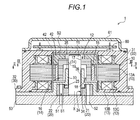
Fig. 1 is a sectional view of an electric pump of a first embodiment; -
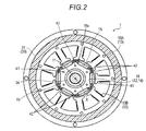
Fig. 2 is a sectional view that is taken along arrow line II-II ofFig. 1 ; -
Fig. 3 is a sectional view that is taken along arrow line III-III ofFig. 1 ; and -
Fig. 4 is a sectional view of an electric pump of a second embodiment. - Hereinafter, embodiments of this disclosure will be described with reference to the drawings. An electric pump of the embodiments includes, for example, an oil supply system for lubrication in an automobile and the like. However, the application of the electric pump is not limited to the automobile and may be used for supply of fluid other than oil.
- As illustrated in
Figs. 1 to 3 , anelectric pump 1 includes amotor portion 10, apump portion 20, and acase 30 for housing themotor portion 10 and thepump portion 20. Thecase 30 is configured by connecting amotor housing 31 for housing themotor portion 10 and a pump body 32 (an example of the pump main body) for housing thepump portion 20. - The
motor portion 10 is configured to include ashaft 11 that is rotatably supported around a shaft axis X, amotor rotor 12 that is fixed to one side of theshaft 11 and is integrally rotated with theshaft 11, and a field coil 13 (stator). Thefield coil 13 is disposed in a region surrounding themotor rotor 12 of themotor housing 31. Thefield coil 13 is configured of a plurality oftooth portions 13A of a stator core formed by laminating electromagnetic steel sheets,coil support frames 13C that are disposed above and below thetooth portions 13A, and acoil portion 13B that is wound around thecoil support frame 13C. - The
motor rotor 12 has acylindrical yoke 14 that is formed by laminating the electromagnetic steel sheets (an example of a magnetic body) and apermanent magnet 15 that is disposed in theyoke 14. Theyoke 14 is configured by superposing afirst yoke 16 and asecond yoke 17 in order from a side closer to thepump body 32 in a direction of the shaft axis X of theshaft 11. The electromagnetic steel sheets are laminated and thereby a through-hole 16a continuous along the direction of the shaft axis X is formed in thecylindrical yoke 14. Thepermanent magnet 15 is inserted into the through-hole 16a. A plurality ofpermanent magnets 15 are arranged such that an N pole and an S pole are alternated in a circumferential direction. Themotor rotor 12 is rotated by receiving an electromagnetic force of thefield coil 13. - The
pump portion 20 is configured as a trochoid pump to include aninner rotor 21 that is fixed to theshaft 11 on a side (other side) opposite to themotor portion 10 and is rotated by a driving force of themotor portion 10, and anouter rotor 22 that is disposed on an outer periphery of theinner rotor 21. The trochoid pump is configured such that a plurality of tooth portions of a tooth surface shape according to a trochoidal curve are formed on the outer periphery of theinner rotor 21 and tooth portions having a number of teeth greater than the number of teeth of theinner rotor 21 by one are formed on an inner periphery of theouter rotor 22. Theinner rotor 21 is rotated around the shaft axis X and theouter rotor 22 is rotated around an eccentric shaft to be spaced apart from the shaft axis X. - In the
case 30, themotor housing 31 is formed of a resin material and thepump body 32 is formed of a metal material. Themotor housing 31 and thepump body 32 are connected by bolts and the like in a state of being superposed in a direction along the shaft axis X. - The
motor housing 31 is a cylindrical body, thefield coil 13 is fixed to the inner peripheral surface thereof, and a housing space S2 of themotor rotor 12 is provided on the inner periphery side of thefield coil 13. Thepump body 32 has a housing space S1 of thepump portion 20 that is formed in a recessed shape on a side opposite to themotor rotor 12 in the direction of the shaft axis X. Acontrol substrate 60 is disposed in an end surface of themotor housing 31 and thecontrol substrate 60 is covered by alid portion 61. Apump cover 50 is provided in the end surface of thepump body 32 in which the housing space S1 is formed. In the embodiment, the pump main body is configured of thepump body 32 and thepump cover 50. Thepump cover 50 is formed of a plate of, for example, the metal material and includes asuction port 51 and adischarge port 52. - The
pump body 32 has a bearingportion 33 that supports theshaft 11 at a portion between themotor portion 10 and thepump portion 20. Theshaft 11 and the bearingportion 33 are formed of a ferrous material. If theshaft 11 and the bearingportion 33 are formed of the same ferrous material, thermal expansion coefficients of theshaft 11 and the bearingportion 33 are close to each other, and a change in a clearance between theshaft 11 and the bearingportion 33 is reduced. Therefore, it is possible to strictly set an interval between theshaft 11 and the bearingportion 33. Thus, it is possible to stably hold a rotation of theshaft 11 by the bearingportion 33. Moreover, in the embodiment, thepump body 32 is configured of the ferrous material itself. - The bearing
portion 33 includes a first extendingportion 34 that is positioned in the housing space S1 of thepump portion 20 and a second extendingportion 35 that is positioned in the housing space S2 of themotor rotor 12. A bearing hole 36 into which theshaft 11 is inserted is formed in the bearingportion 33. - A first recessed
portion 23 and a press-fit hole 24 having a diameter smaller than that of the first recessedportion 23 are formed in theinner rotor 21 of thepump portion 20 in order from a side closer to the bearingportion 33 in the direction of the shaft axis X. The first recessedportion 23 has a diameter into which the first extendingportion 34 is able to be inserted. The first recessedportion 23 is formed on a side facing thepump body 32 in the direction of the shaft axis X, but does not communicate with a suction chamber and a discharge chamber (not illustrated) provided in thepump body 32. - The bearing
portion 33 is extended to the inside of theinner rotor 21 of thepump portion 20 in a radial direction by inserting the first extendingportion 34 into the first recessedportion 23. Therefore, it is possible to widely set a region in which the bearingportion 33 journals theshaft 11. Furthermore, a mounting position of theinner rotor 21 on theshaft 11 and a position of the bearingportion 33 supporting theshaft 11 are closer to each other along a longitudinal direction of theshaft 11. Therefore, in a case where a force to incline a rotation surface of theinner rotor 21 acts on theinner rotor 21 and is transmitted to theshaft 11, the bearingportion 33 journals the portion of theshaft 11 to which the force is transmitted. Therefore, there is no room for bending deformation of theshaft 11. Since the bearingportion 33 is required only to receive the force to incline theshaft 11, it is possible to significantly reduce the occurrence of a pressing force and a frictional force generated between the bearingportion 33 and theshaft 11. As a result, a rotational operation of theshaft 11 is stabilized, the occurrence of noise and vibration is suppressed, and it is possible to suppress wear of the bearingportion 33. - The
yoke 14 of themotor rotor 12 is configured by superposing thefirst yoke 16 and thesecond yoke 17 in order from a side closer to thepump body 32 in the direction of the shaft axis X. Thefirst yoke 16 is positioned on the inner peripheral surface of thecoil portion 13B. On the other hand, thesecond yoke 17 is provided continuous to thefirst yoke 16 and protrudes on a side opposite to thepump portion 20 in the direction of the shaft axis X. A second recessedportion 18 is formed in thefirst yoke 16 and a press-fit hole 19 having a diameter smaller than that of the second recessedportion 18 is formed in thesecond yoke 17. Theshaft 11 and the second extendingportion 35 of the bearingportion 33 are inserted into the second recessedportion 18 of thefirst yoke 16 to be disposed and the end portion of theshaft 11 is press-fitted into the press-fit hole 19 of thesecond yoke 17 to be fixed. - Then, the bearing
portion 33 is disposed to extend to the inside of themotor rotor 12 in the radial direction and thereby the bearingportion 33 can widely set a region in which the bearingportion 33 can journal theshaft 11. Furthermore, since the bearing portion 33 (second extending portion 35) is positioned on the inside of themotor rotor 12 in the radial direction, the axial deflection of theshaft 11 due to the oscillation of themotor rotor 12 is suppressed. Therefore, the rotational operation of theshaft 11 is further stabilized and a wear prevention effect of the bearingportion 33 is also increased. - A distance between the outer peripheral surface of the second extending
portion 35 of the bearingportion 33 and the inner peripheral surface of thefirst yoke 16 is set to be greater than a distance between the outer peripheral surface of thefirst yoke 16 and thefield coil 13. Thefirst yoke 16 and thefield coil 13 are disposed with an extremely narrow interval so that the electromagnetic force efficiently acts on themotor portion 10. On the other hand, the second extendingportion 35 and thefirst yoke 16 may be disposed with an interval in which neither are in contact with each other and strict setting of the interval is not required. - A
dowel 41 is formed in each of the laminated electromagnetic steel sheets configuring theyoke 14 and a plurality of electromagnetic steel sheets are cylindrically laminated by thedowels 41. Thecylindrical yoke 14 includes aresin portion 42 with which a portion over the inside of thefirst yoke 16 and a surface of theshaft 11 on the end portion side from the outer peripheral side in thesecond yoke 17 are filled. Theresin portion 42 of thefirst yoke 16 is configured of resin with which spaces of thepermanent magnet 15 of the through-hole 16a on both end sides are filled. The laminated electromagnetic steel sheets are connected by theresin portion 42 and thereby a shape of theyoke 14 is held. Theresin portion 42 may be provided at least in the direction of the shaft axis X of themotor rotor 12. - In the embodiment, as illustrated in
Fig. 4 , ashaft 11 is configured such that an end portion protruding from apump portion 20 is journaled by a member disposed closer to thepump portion 20 in addition to a bearingportion 33 of apump body 32. Specifically, as illustrated inFig. 4 , an end portion of theshaft 11 is journaled by apump cover 50 covering thepump portion 20. Thepump cover 50 is connected to thepump body 32. A recessedportion 53 around a shaft axis X is formed in thepump cover 50 and the end portion of theshaft 11 is journaled by the recessedportion 53. As described above, since theshaft 11 is journaled in two portions (bearingportion 33 and recessed portion 53) in the direction of the shaft axis X, theshaft 11 is stably supported and a rotational operation is stabilized. - In addition, the
resin portion 42, with which themotor rotor 12 is filled, is provided only in the direction of the shaft axis X and is not provided on the end portion side of theshaft 11 in asecond yoke 17. However, in the embodiment, a thickness of thesecond yoke 17 in the direction of the shaft axis X is set to be greater than that of the first embodiment. Therefore, since a connection region between themotor rotor 12 and theshaft 11 is extended, the rotational operation of theshaft 11 in themotor portion 10 is further stabilized. -
- (1) In the embodiments described above, an example, in which the
resin portion 42 is provided in the direction of the shaft axis X of themotor rotor 12 and the surface of theshaft 11 on the end portion side in thesecond yoke 17, is illustrated, but theresin portion 42 may be provided in a surface of thefirst yoke 16 facing thepump body 32. Theresin portion 42 is present in both end surfaces of themotor rotor 12 in the direction of the shaft axis X and thereby a shape of theyoke 14 in the direction of the shaft axis X is stabilized by being sandwiched by theresin portions 42. For the rest, themotor rotor 12 is configured such that a plurality ofpermanent magnets 15 are disposed on an outer peripheral surface of thefirst yoke 16 and theresin portion 42 may be formed by being filled with resin between adjacentpermanent magnets 15 in the direction of the shaft axis X. - (2) In the embodiments described above, an example, in which the shape of the
cylindrical yoke 14 is held by combining thedowels 41 and theresin portion 42, is illustrated, but in a case where the shape of thecylindrical yoke 14 can be held only by theresin portion 42, thedowels 41 may not be provided in the steel sheets of theyoke 14. For the rest, the shape of theyoke 14 may be held by welding the laminated electromagnetic steel sheets without providing theresin portion 42. - (3) In the embodiments described above, an example, in which the pump main body is configured of two members of the
pump body 32 and thepump cover 50, is illustrated, but the pump main body may be configured of one member that is formed by integrating thepump body 32 and thepump cover 50. - This disclosure can be widely used in the electric pump in which the motor portion and the pump portion are housed.
- The principles, preferred embodiment and mode of operation of the present invention have been described in the foregoing specification. However, the invention which is intended to be protected is not to be construed as limited to the particular embodiments disclosed. Further, the embodiments described herein are to be regarded as illustrative rather than restrictive. Variations and changes may be made by others, and equivalents employed, without departing from the spirit of the present invention. Accordingly, it is expressly intended that all such variations, changes and equivalents which fall within the spirit and scope of the present invention as defined in the claims, be embraced thereby
- It is explicitly stated that all features disclosed in the description and/or the claims are intended to be disclosed separately and independently from each other for the purpose of original disclosure as well as for the purpose of restricting the claimed invention independent of the composition of the features in the embodiments and/or the claims. It is explicitly stated that all value ranges or indications of groups of entities disclose every possible intermediate value or intermediate entity for the purpose of original disclosure as well as for the purpose of restricting the claimed invention, in particular as limits of value ranges.
Claims (6)
- An electric pump (1) comprising:a motor rotor (12) that has a cylindrical yoke (14) and is rotated by an electromagnetic force;a pump portion (20) that has an outer rotor (22) and an inner rotor (21);a shaft (11) that transmits a rotational force from the motor rotor to the pump portion (20) by fixing the motor rotor (12) on one side and fixing the inner rotor (21) on the other side;a motor housing (31) in which a coil portion (13B) is fixed to an inner peripheral surface and the motor rotor (12) is housed on the inside of the coil portion (13B); anda pump main body (32) that houses the pump portion (20),wherein the pump main body (32) has a bearing portion (33) that supports a portion of the shaft (11) between the motor rotor (12) and the inner rotor (21), andwherein the inner rotor (21) has a first recessed portion (23) of a diameter greater than that of the shaft (11) on a side facing the bearing portion and a part of the bearing portion is inserted into the first recessed portion (23) to be disposed.
- The electric pump according to claim 1,
wherein the motor rotor (12) has a second recessed portion (18) of a diameter greater than that of the shaft (11) on a side facing the bearing portion (33) and a part of the bearing portion (33) is inserted into the second recessed portion (18) to be disposed. - The electric pump according to claim 2,
wherein the yoke (14) includes a first yoke (16) that is positioned on an inner peripheral side of the coil portion (13B) and a second yoke (17) that is provided continuously to the first yoke (16) and protrudes on a side opposite to the pump portion (20) with respect to the first yoke (16) in an axial direction of the yoke (14), and
wherein a hole portion (19) capable of fixing the shaft (11) is formed in the second yoke (17) and the second recessed portion (18) is formed on a side facing the bearing portion in the first yoke (16). - The electric pump according to any one of claims 1 to 3,
wherein an end portion of the shaft (11) protruding from the pump portion is journaled by the pump main body (32). - The electric pump according to any one of claims 1 to 4,
wherein the shaft (11) and the bearing portion (38) are formed of a ferrous material. - The electric pump according to any one of claims 1 to 5,
wherein the cylindrical yoke (14) includes magnetic bodies that are laminated so that a through-hole (16a) continuous along the axial direction of the yoke (14) is formed and a resin portion (42) with which the through-hole is filled.
Applications Claiming Priority (1)
| Application Number | Priority Date | Filing Date | Title |
|---|---|---|---|
| JP2015114976A JP2017002749A (en) | 2015-06-05 | 2015-06-05 | Electric pump |
Publications (1)
| Publication Number | Publication Date |
|---|---|
| EP3101784A1 true EP3101784A1 (en) | 2016-12-07 |
Family
ID=56096530
Family Applications (1)
| Application Number | Title | Priority Date | Filing Date |
|---|---|---|---|
| EP16172158.4A Withdrawn EP3101784A1 (en) | 2015-06-05 | 2016-05-31 | Electric pump |
Country Status (4)
| Country | Link |
|---|---|
| US (1) | US20160356271A1 (en) |
| EP (1) | EP3101784A1 (en) |
| JP (1) | JP2017002749A (en) |
| CN (1) | CN205779686U (en) |
Cited By (3)
| Publication number | Priority date | Publication date | Assignee | Title |
|---|---|---|---|---|
| US11437900B2 (en) | 2019-12-19 | 2022-09-06 | Black & Decker Inc. | Modular outer-rotor brushless motor for a power tool |
| US11757330B2 (en) | 2019-12-19 | 2023-09-12 | Black & Decker, Inc. | Canned outer-rotor brushless motor for a power tool |
| US12176794B2 (en) | 2021-11-19 | 2024-12-24 | Black & Decker Inc. | Outer-rotor brushless motor for a power tool |
Families Citing this family (4)
| Publication number | Priority date | Publication date | Assignee | Title |
|---|---|---|---|---|
| DE102017223715A1 (en) * | 2017-12-22 | 2019-06-27 | Magna Powertrain Bad Homburg GmbH | Gerotor pump and method for producing such |
| JP2019143873A (en) * | 2018-02-21 | 2019-08-29 | 株式会社ホクエイ | Liquid fuel supply device |
| CN114837792A (en) | 2021-03-10 | 2022-08-02 | 美普盛(上海)汽车零部件有限公司 | Electric coolant pump with expansion compensation sealing element |
| DE102022108852A1 (en) | 2022-04-12 | 2023-10-12 | Hanon Systems Efp Deutschland Gmbh | Device for conveying a liquid |
Citations (7)
| Publication number | Priority date | Publication date | Assignee | Title |
|---|---|---|---|---|
| US3801231A (en) * | 1971-08-24 | 1974-04-02 | Bosch Gmbh Robert | Pump and electric drive motor unit |
| US5340293A (en) * | 1991-10-30 | 1994-08-23 | Nippondenso Co., Ltd. | Gear-type pump having pressure balanced support |
| EP1464837A1 (en) * | 2003-04-02 | 2004-10-06 | Delphi Technologies, Inc. | Balanced pressure gerotor fuel pump |
| JP2010144595A (en) | 2008-12-18 | 2010-07-01 | Aisin Seiki Co Ltd | Electric pump |
| EP2336565A1 (en) * | 2008-10-14 | 2011-06-22 | JTEKT Corporation | Electric pump unit |
| WO2014115249A1 (en) * | 2013-01-22 | 2014-07-31 | 三菱電機株式会社 | Pump, method for manufacturing pump, and refrigeration cycle device |
| US20140241914A1 (en) * | 2013-02-22 | 2014-08-28 | Ebara Corporation | Vacuum pump motor rotor, motor including same and vacuum pump |
-
2015
- 2015-06-05 JP JP2015114976A patent/JP2017002749A/en active Pending
-
2016
- 2016-05-30 CN CN201620514230.4U patent/CN205779686U/en not_active Expired - Fee Related
- 2016-05-31 EP EP16172158.4A patent/EP3101784A1/en not_active Withdrawn
- 2016-06-01 US US15/169,886 patent/US20160356271A1/en not_active Abandoned
Patent Citations (7)
| Publication number | Priority date | Publication date | Assignee | Title |
|---|---|---|---|---|
| US3801231A (en) * | 1971-08-24 | 1974-04-02 | Bosch Gmbh Robert | Pump and electric drive motor unit |
| US5340293A (en) * | 1991-10-30 | 1994-08-23 | Nippondenso Co., Ltd. | Gear-type pump having pressure balanced support |
| EP1464837A1 (en) * | 2003-04-02 | 2004-10-06 | Delphi Technologies, Inc. | Balanced pressure gerotor fuel pump |
| EP2336565A1 (en) * | 2008-10-14 | 2011-06-22 | JTEKT Corporation | Electric pump unit |
| JP2010144595A (en) | 2008-12-18 | 2010-07-01 | Aisin Seiki Co Ltd | Electric pump |
| WO2014115249A1 (en) * | 2013-01-22 | 2014-07-31 | 三菱電機株式会社 | Pump, method for manufacturing pump, and refrigeration cycle device |
| US20140241914A1 (en) * | 2013-02-22 | 2014-08-28 | Ebara Corporation | Vacuum pump motor rotor, motor including same and vacuum pump |
Cited By (4)
| Publication number | Priority date | Publication date | Assignee | Title |
|---|---|---|---|---|
| US11437900B2 (en) | 2019-12-19 | 2022-09-06 | Black & Decker Inc. | Modular outer-rotor brushless motor for a power tool |
| US11757330B2 (en) | 2019-12-19 | 2023-09-12 | Black & Decker, Inc. | Canned outer-rotor brushless motor for a power tool |
| US12218567B2 (en) | 2019-12-19 | 2025-02-04 | Black & Decker Inc. | Power tool having an outer-rotor brushless motor |
| US12176794B2 (en) | 2021-11-19 | 2024-12-24 | Black & Decker Inc. | Outer-rotor brushless motor for a power tool |
Also Published As
| Publication number | Publication date |
|---|---|
| JP2017002749A (en) | 2017-01-05 |
| US20160356271A1 (en) | 2016-12-08 |
| CN205779686U (en) | 2016-12-07 |
Similar Documents
| Publication | Publication Date | Title |
|---|---|---|
| US20160356271A1 (en) | Electric pump | |
| JP5186291B2 (en) | motor | |
| KR102553651B1 (en) | Gear Motor and Method for Assembling it | |
| US7986068B2 (en) | Motor | |
| US11355978B2 (en) | Rotor, motor, and electric power steering device | |
| JP2012082792A (en) | Electric compressor | |
| US8648503B2 (en) | Arrangement for acoustic decoupling of a stator of an electric motor | |
| CN104578540B (en) | Electric rotating machine | |
| WO2016084319A1 (en) | Inner-rotor-type motor and electric tool provided with same | |
| US20160079828A1 (en) | Bearing arrangement in an electric motor | |
| WO2017077585A1 (en) | Electric motor | |
| CN112838692A (en) | Rotors and Electric Motors | |
| JP2016129473A (en) | motor | |
| JP2017158408A (en) | Rotor and manufacturing method of the same | |
| US11418075B2 (en) | Rotor, motor, and electric power steering device | |
| JP6957631B2 (en) | Rotating machine | |
| JP2018133948A (en) | motor | |
| JP6655560B2 (en) | Rotating electric machine | |
| CN105122600B (en) | The rotor of rotating machinery | |
| KR20190050278A (en) | Power transmission apparatus | |
| JP2010144595A (en) | Electric pump | |
| CN111434012A (en) | Gear system with motor | |
| JP2020010452A (en) | Rotor and motor | |
| JP2019002816A (en) | Rotation angle detector and drive motor for vehicles equipped with rotation angle detector | |
| WO2021095654A1 (en) | Rotary actuator |
Legal Events
| Date | Code | Title | Description |
|---|---|---|---|
| PUAI | Public reference made under article 153(3) epc to a published international application that has entered the european phase |
Free format text: ORIGINAL CODE: 0009012 |
|
| AK | Designated contracting states |
Kind code of ref document: A1 Designated state(s): AL AT BE BG CH CY CZ DE DK EE ES FI FR GB GR HR HU IE IS IT LI LT LU LV MC MK MT NL NO PL PT RO RS SE SI SK SM TR |
|
| AX | Request for extension of the european patent |
Extension state: BA ME |
|
| STAA | Information on the status of an ep patent application or granted ep patent |
Free format text: STATUS: THE APPLICATION IS DEEMED TO BE WITHDRAWN |
|
| 18D | Application deemed to be withdrawn |
Effective date: 20170608 |