EP3101595A2 - Image forming apparatus and method for setting apparatus - Google Patents
Image forming apparatus and method for setting apparatus Download PDFInfo
- Publication number
- EP3101595A2 EP3101595A2 EP16160493.9A EP16160493A EP3101595A2 EP 3101595 A2 EP3101595 A2 EP 3101595A2 EP 16160493 A EP16160493 A EP 16160493A EP 3101595 A2 EP3101595 A2 EP 3101595A2
- Authority
- EP
- European Patent Office
- Prior art keywords
- mode
- information terminal
- information
- terminal device
- unit
- Prior art date
- Legal status (The legal status is an assumption and is not a legal conclusion. Google has not performed a legal analysis and makes no representation as to the accuracy of the status listed.)
- Granted
Links
Images


Classifications
-
- H—ELECTRICITY
- H04—ELECTRIC COMMUNICATION TECHNIQUE
- H04N—PICTORIAL COMMUNICATION, e.g. TELEVISION
- H04N1/00—Scanning, transmission or reproduction of documents or the like, e.g. facsimile transmission; Details thereof
- H04N1/00885—Power supply means, e.g. arrangements for the control of power supply to the apparatus or components thereof
- H04N1/00888—Control thereof
-
- G—PHYSICS
- G06—COMPUTING OR CALCULATING; COUNTING
- G06F—ELECTRIC DIGITAL DATA PROCESSING
- G06F3/00—Input arrangements for transferring data to be processed into a form capable of being handled by the computer; Output arrangements for transferring data from processing unit to output unit, e.g. interface arrangements
-
- G—PHYSICS
- G06—COMPUTING OR CALCULATING; COUNTING
- G06F—ELECTRIC DIGITAL DATA PROCESSING
- G06F3/00—Input arrangements for transferring data to be processed into a form capable of being handled by the computer; Output arrangements for transferring data from processing unit to output unit, e.g. interface arrangements
- G06F3/12—Digital output to print unit, e.g. line printer, chain printer
- G06F3/1201—Dedicated interfaces to print systems
- G06F3/1202—Dedicated interfaces to print systems specifically adapted to achieve a particular effect
- G06F3/1211—Improving printing performance
- G06F3/1212—Improving printing performance achieving reduced delay between job submission and print start
-
- G—PHYSICS
- G06—COMPUTING OR CALCULATING; COUNTING
- G06F—ELECTRIC DIGITAL DATA PROCESSING
- G06F3/00—Input arrangements for transferring data to be processed into a form capable of being handled by the computer; Output arrangements for transferring data from processing unit to output unit, e.g. interface arrangements
- G06F3/12—Digital output to print unit, e.g. line printer, chain printer
- G06F3/1201—Dedicated interfaces to print systems
- G06F3/1202—Dedicated interfaces to print systems specifically adapted to achieve a particular effect
- G06F3/1218—Reducing or saving of used resources, e.g. avoiding waste of consumables or improving usage of hardware resources
- G06F3/1221—Reducing or saving of used resources, e.g. avoiding waste of consumables or improving usage of hardware resources with regard to power consumption
-
- G—PHYSICS
- G06—COMPUTING OR CALCULATING; COUNTING
- G06F—ELECTRIC DIGITAL DATA PROCESSING
- G06F3/00—Input arrangements for transferring data to be processed into a form capable of being handled by the computer; Output arrangements for transferring data from processing unit to output unit, e.g. interface arrangements
- G06F3/12—Digital output to print unit, e.g. line printer, chain printer
- G06F3/1201—Dedicated interfaces to print systems
- G06F3/1223—Dedicated interfaces to print systems specifically adapted to use a particular technique
- G06F3/1229—Printer resources management or printer maintenance, e.g. device status, power levels
-
- G—PHYSICS
- G06—COMPUTING OR CALCULATING; COUNTING
- G06F—ELECTRIC DIGITAL DATA PROCESSING
- G06F3/00—Input arrangements for transferring data to be processed into a form capable of being handled by the computer; Output arrangements for transferring data from processing unit to output unit, e.g. interface arrangements
- G06F3/12—Digital output to print unit, e.g. line printer, chain printer
- G06F3/1201—Dedicated interfaces to print systems
- G06F3/1278—Dedicated interfaces to print systems specifically adapted to adopt a particular infrastructure
- G06F3/1292—Mobile client, e.g. wireless printing
-
- G—PHYSICS
- G06—COMPUTING OR CALCULATING; COUNTING
- G06K—GRAPHICAL DATA READING; PRESENTATION OF DATA; RECORD CARRIERS; HANDLING RECORD CARRIERS
- G06K15/00—Arrangements for producing a permanent visual presentation of the output data, e.g. computer output printers
- G06K15/02—Arrangements for producing a permanent visual presentation of the output data, e.g. computer output printers using printers
- G06K15/18—Conditioning data for presenting it to the physical printing elements
- G06K15/1801—Input data handling means
- G06K15/1803—Receiving particular commands
- G06K15/1806—Receiving job control commands
- G06K15/1809—Receiving job control commands relating to the printing process
-
- G—PHYSICS
- G06—COMPUTING OR CALCULATING; COUNTING
- G06K—GRAPHICAL DATA READING; PRESENTATION OF DATA; RECORD CARRIERS; HANDLING RECORD CARRIERS
- G06K15/00—Arrangements for producing a permanent visual presentation of the output data, e.g. computer output printers
- G06K15/40—Details not directly involved in printing, e.g. machine management, management of the arrangement as a whole or of its constitutive parts
- G06K15/4005—Sharing resources or data with other data processing systems; Preparing such data
-
- G—PHYSICS
- G06—COMPUTING OR CALCULATING; COUNTING
- G06K—GRAPHICAL DATA READING; PRESENTATION OF DATA; RECORD CARRIERS; HANDLING RECORD CARRIERS
- G06K15/00—Arrangements for producing a permanent visual presentation of the output data, e.g. computer output printers
- G06K15/40—Details not directly involved in printing, e.g. machine management, management of the arrangement as a whole or of its constitutive parts
- G06K15/4055—Managing power consumption, e.g. standby mode
-
- H—ELECTRICITY
- H04—ELECTRIC COMMUNICATION TECHNIQUE
- H04N—PICTORIAL COMMUNICATION, e.g. TELEVISION
- H04N1/00—Scanning, transmission or reproduction of documents or the like, e.g. facsimile transmission; Details thereof
- H04N1/00127—Connection or combination of a still picture apparatus with another apparatus, e.g. for storage, processing or transmission of still picture signals or of information associated with a still picture
- H04N1/00281—Connection or combination of a still picture apparatus with another apparatus, e.g. for storage, processing or transmission of still picture signals or of information associated with a still picture with a telecommunication apparatus, e.g. a switched network of teleprinters for the distribution of text-based information, a selective call terminal
- H04N1/00307—Connection or combination of a still picture apparatus with another apparatus, e.g. for storage, processing or transmission of still picture signals or of information associated with a still picture with a telecommunication apparatus, e.g. a switched network of teleprinters for the distribution of text-based information, a selective call terminal with a mobile telephone apparatus
-
- H—ELECTRICITY
- H04—ELECTRIC COMMUNICATION TECHNIQUE
- H04N—PICTORIAL COMMUNICATION, e.g. TELEVISION
- H04N1/00—Scanning, transmission or reproduction of documents or the like, e.g. facsimile transmission; Details thereof
- H04N1/00127—Connection or combination of a still picture apparatus with another apparatus, e.g. for storage, processing or transmission of still picture signals or of information associated with a still picture
- H04N1/00281—Connection or combination of a still picture apparatus with another apparatus, e.g. for storage, processing or transmission of still picture signals or of information associated with a still picture with a telecommunication apparatus, e.g. a switched network of teleprinters for the distribution of text-based information, a selective call terminal
- H04N1/00315—Connection or combination of a still picture apparatus with another apparatus, e.g. for storage, processing or transmission of still picture signals or of information associated with a still picture with a telecommunication apparatus, e.g. a switched network of teleprinters for the distribution of text-based information, a selective call terminal with a radio transmission apparatus
-
- H—ELECTRICITY
- H04—ELECTRIC COMMUNICATION TECHNIQUE
- H04N—PICTORIAL COMMUNICATION, e.g. TELEVISION
- H04N1/00—Scanning, transmission or reproduction of documents or the like, e.g. facsimile transmission; Details thereof
- H04N1/0035—User-machine interface; Control console
- H04N1/00352—Input means
- H04N1/00355—Mark-sheet input
-
- H—ELECTRICITY
- H04—ELECTRIC COMMUNICATION TECHNIQUE
- H04N—PICTORIAL COMMUNICATION, e.g. TELEVISION
- H04N1/00—Scanning, transmission or reproduction of documents or the like, e.g. facsimile transmission; Details thereof
- H04N1/00885—Power supply means, e.g. arrangements for the control of power supply to the apparatus or components thereof
- H04N1/00888—Control thereof
- H04N1/00891—Switching on or off, e.g. for saving power when not in use
-
- H—ELECTRICITY
- H04—ELECTRIC COMMUNICATION TECHNIQUE
- H04N—PICTORIAL COMMUNICATION, e.g. TELEVISION
- H04N1/00—Scanning, transmission or reproduction of documents or the like, e.g. facsimile transmission; Details thereof
- H04N1/32—Circuits or arrangements for control or supervision between transmitter and receiver or between image input and image output device, e.g. between a still-image camera and its memory or between a still-image camera and a printer device
- H04N1/32101—Display, printing, storage or transmission of additional information, e.g. ID code, date and time or title
-
- H—ELECTRICITY
- H04—ELECTRIC COMMUNICATION TECHNIQUE
- H04W—WIRELESS COMMUNICATION NETWORKS
- H04W24/00—Supervisory, monitoring or testing arrangements
- H04W24/08—Testing, supervising or monitoring using real traffic
-
- H—ELECTRICITY
- H04—ELECTRIC COMMUNICATION TECHNIQUE
- H04N—PICTORIAL COMMUNICATION, e.g. TELEVISION
- H04N2201/00—Indexing scheme relating to scanning, transmission or reproduction of documents or the like, and to details thereof
- H04N2201/0077—Types of the still picture apparatus
- H04N2201/0094—Multifunctional device, i.e. a device capable of all of reading, reproducing, copying, facsimile transception, file transception
-
- Y—GENERAL TAGGING OF NEW TECHNOLOGICAL DEVELOPMENTS; GENERAL TAGGING OF CROSS-SECTIONAL TECHNOLOGIES SPANNING OVER SEVERAL SECTIONS OF THE IPC; TECHNICAL SUBJECTS COVERED BY FORMER USPC CROSS-REFERENCE ART COLLECTIONS [XRACs] AND DIGESTS
- Y02—TECHNOLOGIES OR APPLICATIONS FOR MITIGATION OR ADAPTATION AGAINST CLIMATE CHANGE
- Y02D—CLIMATE CHANGE MITIGATION TECHNOLOGIES IN INFORMATION AND COMMUNICATION TECHNOLOGIES [ICT], I.E. INFORMATION AND COMMUNICATION TECHNOLOGIES AIMING AT THE REDUCTION OF THEIR OWN ENERGY USE
- Y02D10/00—Energy efficient computing, e.g. low power processors, power management or thermal management
Definitions
- the present invention relates to an image forming apparatus and a method for setting an apparatus, and more particularly, to an image forming apparatus that forms an image on a recording medium by using an electrophotographic method.
- Japanese Patent Application Publication No. 2009-160746 discloses a printer including a reader for communicating with a non-contact integrated circuit (IC) card.
- IC integrated circuit
- An aspect of the present invention is intended to provide an image forming apparatus and a method for setting an apparatus that are capable of improving user-friendliness.
- an image forming apparatus including: a storage unit configured to store identification information identifying an information terminal device and mode information indicating a mode corresponding to the information terminal device in association with each other; a communication unit configured to receive from the information terminal device a wireless signal including identification information that is stored in the information terminal device and identifies the information terminal device, and determine an intensity of the received wireless signal; and a control unit configured to, when determining that the determined intensity of the received wireless signal is equal to or greater than a predetermined intensity, read from the storage unit the mode information corresponding to the identification information included in the received wireless signal, and set the image forming apparatus to the mode indicated by the read mode information.
- a method for setting an apparatus including: receiving, by a communication unit, from an information terminal device, a wireless signal including identification information that is stored in the information terminal device and identifies the information terminal device; determining, by a signal intensity determination unit, an intensity of the wireless signal received from the information terminal device; determining, by a determination unit, whether the determined intensity of the received wireless signal is equal to or greater than a predetermined intensity; and when it is determined that the determined intensity of the received wireless signal is equal to or greater than the predetermined intensity, reading mode information corresponding to the identification information included in the received wireless signal and indicating a mode corresponding to the information terminal device, from a storage unit storing the identification information and the mode information in association with each other, and setting, by a setting unit, the apparatus to the mode indicated by the read mode information.
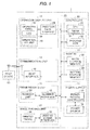
- FIG. 1 illustrates a multifunction printer or peripheral (MFP) 1.
- the MFP 1 has multiple functions, such as printing, image scanning, faxing, and copying.
- the MFP 1 includes a controller (or control unit) 10, a memory (or storage unit) 12, an operation display unit (or operation display) 14, a communication unit (or communication interface) 16, an image reading unit (or image reader) 18, an image forming unit (or printing device) 20, and a power supply (or power supply unit) 22. These units are connected to each other via an address/data bus 23.
- the communication unit 16 serves as a signal intensity determination unit (or signal intensity determiner).
- the controller 10 serves as a determination unit (or determiner) and a setting unit (or setter).
- the controller 10 includes a central processing unit (CPU) 24 and a program read only memory (ROM) 28.
- the CPU 24 reads a predetermined program from the program ROM 28 and executes it, thereby performing system control of the entire MFP 1, management of the flow of image information, or the like and controlling the MFP 1.
- the CPU 24 includes a timer 26 and can measure a predetermined time period in accordance with control program data stored in the program ROM 28.
- the memory 12 includes a data storage memory 30 and an apparatus setting information storage memory (referred to below simply as the setting storage memory) 32.
- the data storage memory 30 is a memory for storing image information.
- the setting storage memory 32 is a memory for storing information regarding operation of the MFP 1.
- the CPU 24 reads and stores information from and in the setting storage memory 32 via the address/data bus 23.
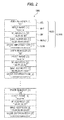
- the setting storage memory 32 stores apparatus setting information IMS.
- the apparatus setting information IMS includes, for each of one or more users of the MFP 1, user apparatus setting information IUMS unique to the user.
- the user apparatus setting information IUMS includes a user identification information item IUID that is identification information unique to a host device 60 as an information terminal device carried by the user and a mode information item (or apparatus setting mode information item) ISM corresponding to the user identification information item IUID.
- the user identification information item IUID consists of a user number IID, a host name IHT, an internet protocol (IP) address IIP, and a media access control (MAC) address IMAC.
- IP internet protocol
- MAC media access control
- the mode information item ISM indicates a mode (or operating mode) of the MFP 1 corresponding to the host device 60.
- the mode information item ISM is information indicating settings regarding operation modes, such as a copy mode, a scan mode, and a print mode, and resolution, paper setting, a duplex mode, or the like in each of the operation modes.
- the apparatus setting information IMS is predetermined and stored in the setting storage memory 32 prior to printing.
- the operation display unit 14 serves as an operation unit or user interface.
- the operation display unit 14 includes an operation panel 36 and an operation panel interface 34.
- the operation panel 36 includes a liquid crystal display (LCD) 38 and an operation key unit 40.
- the operation panel 36 serves as a man-machine interface between the MFP 1 and a user.
- the LCD 38 is a display for displaying information input by a user, a control state of the MFP 1, or other information.
- the operation key unit 40 includes keyboard switches by which a user can input desired control content or other information.
- the operation panel interface 34 is between the address/data bus 23 and the operation panel 36 and is an interface circuit for sending and receiving signals.
- a user By operating the operation key unit 40, a user can set the user identification information item IUID (user number IID, host name IHT, IP address IIP, MAC address IMAC, etc.) that is unique information identifying the host device 60 carried by the user, and the mode information item ISM indicating functions and settings usually used by the user for printing in the MFP 1.
- the CPU 24 receives setting information from users via the operation panel interface 34 and stores content of the received setting information in the setting storage memory 32 as the apparatus setting information IMS.
- the communication unit 16 includes a host interface 42.
- the CPU 24 can communicate with a host device 60 via the host interface 42.
- the host interface 42 is an interface conforming to wireless local area network (LAN) standards, such as Institute of Electrical and Electronics Engineers (IEEE) 802.11a/b/g/n/ac.
- the host interface 42 sends and receives, to and from a host device 60, image information, apparatus information, or other information.
- the host device 60 is a portable mobile device, such as a personal computer, a smartphone, or tablet, including an interface conforming to wireless LAN standards, such as IEEE 802.11a/b/g/n/ac, similarly to the MFP 1.
- the host device 60 is carried by the user.
- the image reading unit 18 includes a scanner unit 50 and a scanner interface 48.
- the scanner unit 50 reads an original to obtain image information.
- the scanner interface 48 is an interface circuit for transferring image information from the scanner unit 50, and sending and receiving control signals, in accordance with instructions from the CPU 24.
- the image forming unit 20 includes a printer engine 54 and a printer engine interface 52.
- the printer engine 54 receives image information and prints an image on a printing paper sheet in accordance with the received image information.
- the printer engine interface 52 is an interface circuit for transferring image information to the printer engine 54, and sending and receiving control signals, in accordance with instructions from the CPU 24.
- the power supply 22 includes a power source (or power source unit) 58 and a power source controller (or power source control unit) 56.
- the power source 58 supplies electrical power to components in the MFP 1 under control of the power source controller 56.
- the power source controller 56 controls the power source 58 to turn on and off the power supply to the components in the MFP 1.
- An on/off setting of the power supply can be set through the operation panel 36.
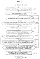
- step SP1 the CPU 24 controls the power source controller 56 to supply power from the power source 58 to each component in the MFP 1, then proceeding to step SP2.
- step SP2 the CPU 24 performs initial setting of peripheral large scale integrations (LSIs) in the MFP 1 and initial setting such as initialization of memories in the MFP 1.
- LSIs peripheral large scale integrations
- the CPU 24 performs print preparation control of the printer engine 54 via the printer engine interface 52, performs original reading preparation control of the scanner unit 50 via the scanner interface 48, and enables the host interface 42 to communicate with a host devices 60.
- step SP3 the CPU 24 proceeds to step SP3, and periodically performs detection of a wireless LAN radio wave generated by a host device 60 by using the host interface 42 and determines whether a wireless LAN radio wave has been detected.
- the CPU 24 waits until it detects a wireless LAN radio wave. If the CPU 24 makes a positive determination in step SP3, it proceeds to step SP4. This positive determination indicates that a user who may use the MFP 1 now has approached the MFP 1.
- step SP4 the CPU 24 analyzes data (a header and data in a data packet) in the detected wireless LAN radio wave and extracts from the data a user identification information item IUID (host name IHT, IP address IIP, MAC address IMAC, etc.). The CPU 24 then compares the user identification information item (referred to as the obtained user identification information item) obtained from the host device 60 with the one or more user identification information items (referred to as the registered user identification information items) previously stored in the setting storage memory 32, and determines whether the obtained user identification information item matches one of the registered user identification information items. If a positive determination is made in this step, the CPU 24 proceeds to step SP5.
- IUID user identification information item obtained from the host device 60
- the one or more user identification information items referred to as the registered user identification information items
- This positive determination indicates that a user carrying a host device 60 previously registered with the setting storage memory 32 exists within the range (referred to as the radio wave detectable range) in which the host device 60 is near enough for the MFP 1 to detect a wireless LAN radio wave from the host device 60.
- the CPU 24 returns to step SP3 and waits for detection of a wireless LAN radio wave. This negative determination indicates that a wireless LAN radio wave has been detected but the device generating the radio wave is not previously registered with the setting storage memory 32.
- step SP5 the CPU 24 obtains the intensity of the radio wave from the host device 60 via the host interface 42, then proceeding to step SP6.
- step SP6 the CPU 24 determines whether the obtained intensity of the radio wave is equal to or greater than a threshold. This threshold is set so that, when a user approaches the MFP 1 close enough to be considered to be likely to use the MFP 1 now (or when a user is near the MFP), the intensity of a wireless LAN radio wave emitted by a host device 60 carried by the user is equal to or greater than the threshold. If a positive determination is made in this step, the CPU 24 proceeds to step SP7. This positive determination indicates that a user carrying a host device 60 previously registered with the setting storage memory 32 exists near the MFP 1.
- step SP6 the CPU 24 returns to step SP3 and waits for detection of a wireless LAN radio wave.
- This negative determination indicates that a wireless LAN radio wave generated by a host device 60 previously registered with the setting storage memory 32 has been detected but the user carrying the host device 60 is not near the MFP 1.
- a host device 60 that has been previously registered with the setting storage memory 32 and whose radio wave has been detected at an intensity equal to or greater than the threshold will be also referred to as a neighboring device.
- step SP7 the CPU 24 determines whether multiple neighboring devices have been detected. If a positive determination is made in this step, the CPU 24 proceeds to step SP8. This positive determination indicates that multiple neighboring devices have been detected and thus it is necessary to select one of the multiple neighboring devices as a selected neighboring device.
- step SP8 the CPU 24 selects the neighboring device having the highest radio wave intensity from among the multiple neighboring devices as a selected neighboring device, then proceeding to step SP9.
- step SP7 the CPU 24 determines the detected neighboring device as a selected neighboring device, then skipping step SP8 and proceeding to step SP9. This negative determination indicates that only one neighboring device has been detected.
- step SP9 the CPU 24 measures time using the timer 26 and determines whether the intensity of the radio wave received from the selected neighboring device remains (or continues to be) equal to or greater than the threshold for a predetermined time period (e.g., several seconds). If a positive determination is made in this step, the CPU 24 determines the selected neighboring device as a determined neighboring device, then proceeding to step SP10. This positive determination indicates that the user carrying the selected neighboring device is extremely likely to use the MFP 1 now. On the other hand, if a negative determination is made in step SP9, the CPU 24 returns to step SP3 and waits for detection of a wireless LAN radio wave. This negative determination indicates that the selected neighboring device has been selected but the user carrying the selected neighboring device has left the vicinity of the MFP 1.
- a predetermined time period e.g., several seconds
- step SP10 the CPU 24 reads, from the setting storage memory 32, the mode information item ISM corresponding to the user identification information item IUID corresponding to the determined neighboring device, and sets the MFP 1 to the mode corresponding to the read mode information item ISM (or configures settings for the MFP 1 based on the read mode information item ISM), then proceeding to step SP11 and ends the print setting process procedure RT1.
- the MFP 1 having the above configuration detects the intensity of a radio wave from a host device 60 previously registered with the MFP 1; if the detected radio wave intensity remains equal to or greater than the threshold for the predetermined time period, the MFP 1 determines that a user carrying the host device 60 has approached the MFP 1 in order to use the MFP 1, and sets the MFP 1 to the mode (or operating mode) corresponding to the host device 60. Thereby, the MFP 1 automatically switches to functions and settings that are usually used by the user about to use the MFP 1. This can save user's time and improve user-friendliness.
- An MFP may include a card reader for communicating with a non-contact IC card, and when the non-contact IC card is brought close to the card reader by a user, read data from the non-contact IC card by the card reader and identify the user based on the read data.
- this MFP includes the card reader, and thus has a complicated structure. Further, the MFP cannot identify a user unless the user approaches the MFP and brings the non-contact IC card close to the card reader. Thus, the user needs to carry the non-contact IC card and perform the troublesome operation.
- the MFP 1 receives a radio wave emitted from a host device 60 carried by a user on a daily basis; when a user approaches the MFP 1, the MFP 1 identifies the user; before the user reaches a position where the user can operate the MFP 1, the MFP 1 is set to the mode corresponding to the user.
- the user need neither operate the MFP 1 nor carry a non-contact IC card in order to allow the MFP 1 to identify the user. This improves user-friendliness.
- the MFP 1 detects the intensity of a wireless LAN radio wave from a host device 60 by using the host interface 42, which may be the same as the host interface of the conventional MFP.
- the MFP 1 needs no additional equipment or component and requires no structural change, reducing additional cost.
- An MFP may detect a user approaching the MFP by using a human sensor (e.g., infrared sensor). However, although this MFP can detect a person approaching the MFP, it cannot identify who the person is. Thus, the MFP cannot set itself to the mode corresponding to the person. Further, when multiple users exist within a range in which a user can operate the MFP, the MFP cannot determine which of the multiple users the MFP should set itself to the mode corresponding to.
- a human sensor e.g., infrared sensor
- the MFP 1 obtains, from a host device 60, the user identification information item IUID unique to the host device 60 via wireless communication. Thereby, the MFP 1 can identify a user about to use the MFP 1. Further, the MFP 1 is more simple in structure than the MFP with the human sensor.
- the MFP 1 detects multiple neighboring devices, it selects the neighboring device having the highest radio wave intensity from among the multiple neighboring devices, as the selected neighboring device. Thus, the MFP 1 can set itself to the mode corresponding to the user closest to the MFP 1. Thereby, if multiple users each carrying a neighboring device exist near the MFP 1, the MFP 1 can set itself to the mode corresponding to the user most likely to use the MFP 1 now.
- the MFP 1 determines the selected neighboring device as the determined neighboring device. This can prevent the MFP 1 from being set to an inappropriate mode. Specifically, when the user carrying the selected neighboring device has left the vicinity of the MFP 1, the MFP 1 can prevent itself from being set to the mode corresponding to the user, who is unlikely to use the MFP 1 now.
- the above-described MFP 1 includes: the memory 12 configured to store a user identification information item IUID as identification information identifying a host device 60 and a mode information item ISM as mode information (or setting mode information) indicating a mode corresponding to the host device 60 in association with each other; the communication unit 16 configured to receive from the host device 60 a wireless signal including a user identification information item IUID that is stored in the host device 60 and identifies the host device 60, and determine an intensity of the received wireless signal; and the controller 10 configured to, when determining that the determined intensity of the received wireless signal is equal to or greater than the predetermined intensity (i.e., the threshold that is an intensity at which the host device 60 is determined to be near the MFP 1), read from the memory 12 the mode information item ISM corresponding to the user identification information item IUID included in the wireless signal received from the host device 60, and set the MFP 1 to the mode indicated by the read mode information item ISM (or configure the MFP 1 based on the read mode information).
- the predetermined intensity
- FIG. 4 illustrates an MFP 101 according to a second embodiment.
- the MFP 101 differs from the MFP 1 of the first embodiment in having a power supply 122 instead of the power supply 22 and a communication unit 116 instead of the communication unit 16, but otherwise is the same.
- the power supply 122 differs from the power supply 22 in having a power source controller 156 instead of the power source controller 56 and a power source 158 instead of the power source 58.
- the power source 158 has power supply modes: a normal power mode in which it supplies predetermined power to the controller 10, memory 12, operation display unit 14, communication unit 116, image reading unit 18, and image forming unit 20; and a power saving mode in which it supplies power only to the operation display unit 14 and communication unit 116 and interrupts power supply to the controller 10, memory 12, image reading unit 18, and image forming unit 20.
- the power source 158 is switched to either the normal power mode or the power saving mode under control of the power source controller 156.
- the MFP 101 is in the power saving mode, only the operation display unit 14 and communication unit 116 operate.
- the function of the MFP 101 is limited to only receiving user's operation and receiving wireless LAN radio waves, it is possible to reduce the power consumption of the entire MFP 101 and save power, as compared to when the MFP 101 is in the normal power mode.
- the communication unit 116 differs from the communication unit 16 in having a sub-CPU 44 and a sub-program ROM 46, but otherwise is the same.
- the sub-CPU 44 In the normal power mode, the sub-CPU 44 reads a predetermined program from the program ROM 28 and executes it, thereby controlling the printer engine 54 (specifically, motors, various sensors, and other components in the printer engine 54) via the printer engine interface 52.
- the sub-CPU 44 reads a predetermined program from the sub-program ROM 46 and executes it, thereby controlling the host interface 42 and communicating with a host device 60 via the host interface 42. As such, the sub-CPU 44 controls the printer engine 54 in the normal power mode and controls the host interface 42 in the power saving mode.
- the sub-CPU 44 is lower in power consumption than the CPU 24.
- the power saving mode can make the power consumption of the MFP 101 minimum.
- the CPU 24 or sub-CPU 44 gives an instruction to the power source controller 156, which controls the power source 58 to switch between the power supply modes in accordance with the instruction.
- the operation key unit 40 in the operation display unit 14 includes a power saving key 40a.
- the power saving key 40a is for instructing to return from the power saving mode to the normal power mode, and operable by a user.
- the CPU 24 and sub-CPU 44 receive operations or instructions from the operation key unit 40 via the operation panel interface 34 and thereby detect that the power saving key 40a has been operated.
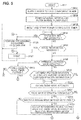
- the CPU 24 supplies power from the power source 158 to each component in the MFP 101 and performs initial setting of peripheral LSIs in the MFP 101 and initial setting such as initialization of memories in the MFP 101, as in step SP1 and SP2 of FIG. 3 .
- the sub-CPU 44 performs print preparation control via the printer engine interface 52, and then the CPU 24 enables communication with host devices via the host interface 42, entering a wait state.
- the MFP 101 is in the normal power mode.
- the CPU 24 proceeds to step SP23, and causes the timer 26 to reset and start a power saving mode timer, then proceeding to step SP24.
- the power saving mode timer measures a predetermined time period (referred to as the power saving mode shift time period). After the power saving mode timer is started, when the power saving mode shift time period elapses without the power saving mode timer being reset, the power saving mode timer expires (or times out).
- the time period (i.e., power saving mode shift time period) of the power saving mode timer is, for example, from 1 minute to about 2 hours.
- step SP 24 the CPU 24 determines whether the operation key unit 40 has been operated by a user. If a positive determination is made in this step, the CPU 24 proceeds to step SP25 and performs processing (e.g., copying or scanning) in accordance with the operation. The CPU 24 then returns to step SP23 and causes the timer 26 to reset and start the power saving mode timer. On the other hand, if a negative determination is made in step SP24, the CPU 24 proceeds to step SP26.
- processing e.g., copying or scanning
- step SP26 the CPU 24 waits for reception of image information (or a print job) via the host interface 42 and determines whether it has received image information to be printed. If a positive determination is made in this step, the CPU 24 proceeds to step SP27. In step SP27, the CPU 24 transfers the received image information to the printer engine 54 via the printer engine interface 52 and controls the printer engine 54 to print the image information. The CPU 24 then returns to step SP23 and causes the timer 26 to reset and start the power saving mode timer. On the other hand, if a negative determination is made in step SP26, the CPU 24 proceeds to step SP28.
- step SP28 the CPU 24 performs detection of a wireless LAN radio wave by using the host interface 42 and determines whether a wireless LAN radio wave has been detected, as in step SP3 of FIG. 3 . If a positive determination is made in step SP28, the CPU 24 proceeds to step SP30. This positive determination indicates that a user who may use the MFP 101 now has approached the MFP 101. On the other hand, if a negative determination is made in step SP28, the CPU 24 proceeds to step SP29.
- step SP29 the CPU 24 checks the power saving mode timer to determine whether the power saving mode timer has expired. If a positive determination is made in this step, the CPU 24 proceeds to step SP39. This positive determination indicates that the MFP 101 should shift to the power saving mode since the power saving mode timer has expired. On the other hand, if a negative determination is made in step SP29, the CPU 24 returns to step SP24 and waits for an user's operation or instruction. This negative determination indicates that the MFP 101 should remain in the normal power mode without shifting to the power saving mode since the power saving mode timer has not expired.
- steps SP30 to SP36 the CPU 24 performs the same processes as those in steps SP4 to SP10 of FIG. 3 , then proceeding to step SP37.
- step SP 37 the CPU 24 measures time using the timer 26 and determines whether the intensity of the radio wave received from the determined neighboring device remains (or continues to be) less than the threshold for a predetermined time period. If a positive determination is made in this step, the CPU 24 proceeds to step SP38. This positive determination indicates that the user carrying the determined neighboring device has left the vicinity of the MFP 101. On the other hand, if a negative determination is made in step SP37, the CPU 24 returns to step SP28 and waits for detection of a wireless LAN radio wave. This negative determination indicates that the user carrying the determined neighboring device is still in the vicinity of the MFP 101.
- step SP38 the CPU 24 determines whether there is at least one neighboring device other than the determined neighboring device that has left the vicinity of the MFP 101. If a positive determination is made in this step, the CPU 24 returns to step SP31. This positive determination indicates that the user carrying the determined neighboring device has left the vicinity of the MFP 101 but there is another neighboring device, and thus the MFP 101 need not shift to the power saving mode. On the other hand, if a negative determination is made in step SP38, the CPU 24 proceeds to step SP39. This negative determination indicates that the user carrying the determined neighboring device has left the vicinity of the MFP 101 and there is no neighboring device, and thus the MFP 101 needs to shift to the power saving mode.
- step SP39 the CPU 24 shifts the MFP 101 to the power saving mode, then proceeding to step SP40.
- the CPU 24 sets the sub-CPU 44 to perform initialization according to a program stored in the sub-program ROM 46, stops control of the host interface 42, and resets the sub-CPU 44.
- the sub-CPU 44 boots up according to the program stored in the sub-program ROM 46, and starts to control the host interface 42.
- the sub-CPU 44 controls the power source controller 156 to supply power to only the communication unit 116 and operation display unit 14 and interrupts power supply to the other components, including the controller 10, memory 12, image reading unit 18, and image forming unit 20.
- step SP40 the sub-CPU 44 waits until the operation key unit 40 is operated, until a wireless LAN radio wave is detected, or until image information is received. In this manner, once the MFP 101 shifts from the normal power mode to the power saving mode, it remains in the power saving mode until a wireless LAN radio wave is detected, until image information is received, or until the operation key unit 40 is operated. Thereby, although the function of the MFP 101 is limited, it is possible to reduce the power consumption of the entire MFP 101 and save power, as compared to the normal power mode. On the other hand, in step SP40, if the operation key unit 40 is operated, if a wireless LAN radio wave is detected, or if image information is received, the sub-CPU 44 proceeds to step SP41.
- step SP41 the sub-CPU 44 shifts the MFP 101 to the normal power mode, then proceeding to step SP42. Specifically, the sub-CPU 44 controls the power source controller 156 to supply power to each component in the MFP 101. This increases the power consumption of the MFP 101, as compared to the power saving mode. Then, the CPU 24 boots up, and initializes the controller 10. When the CPU 24 reaches a state in which it can perform processing, the CPU 24 communicates with the sub-CPU 44 and takes over data processing for the host interface 42 from the sub-CPU 44. After the CPU 24 has taken over the processing from the sub-CPU 44, it sets the sub-CPU 44 to perform initialization according to a program stored in the program ROM 28 and resets the sub-CPU 44. Then, the sub-CPU 44 boots up according to the program stored in the program ROM 28, and starts print preparation control of the printer engine 54 via the printer engine interface 52.
- step SP42 the CPU 24 determines whether the operation key unit 40 has been operated by a user. If a positive determination is made in this step, the CPU 24 proceeds to step SP25, performs processing in accordance with the operation, returns to step SP23, and causes the timer 26 to reset and start the power saving mode timer. On the other hand, if a negative determination is made in step SP42, the CPU 24 proceeds to step SP43.
- step SP43 the CPU 24 waits for reception of image information via the host interface 42 and determines whether it has received image information to be printed. If a positive determination is made in this step, the CPU 24 proceeds to step SP27. In step SP27, the CPU 24 transfers the received image information to the printer engine 54 via the printer engine interface 52 and controls the printer engine 54 to print the image information, then returning to step SP23 and causing the timer 26 to reset and start the power saving mode timer. On the other hand, if a negative determination is made in step SP43, the CPU 24 returns to step SP28 and waits for detection of a wireless LAN radio wave.
- the MFP 101 having the above configuration detects the intensity of a radio wave from a host device 60 previously registered with the MFP 101; if the detected radio wave intensity remains less than the threshold for the predetermined time period, the MFP 101 determines that a user carrying the host device 60 has finished using the MFP 101 and left the MFP 101, and shifts from the normal power mode to the power saving mode.
- the MFP 101 can automatically shift to the power saving mode, thereby reducing the power consumption, as compared to a case where it remains in the normal power mode.
- the MFP 101 keeps the communication unit 116 and operation display unit 14 enabled, and thereby can receive a user's operation, a wireless LAN radio wave, and image information.
- the MFP 101 can promptly return from the power saving mode to the normal power mode.
- An MFP may use a human sensor (e.g., infrared sensor) to detect that a user has left the MFP.
- a human sensor e.g., infrared sensor
- this configuration can detect that a user has left the MFP, but when multiple users are near the MFP and only one of them has left the MFP, it cannot identify who has left the MFP.
- the MFP 101 obtains, from host devices 60, the user identification information items IUID unique to the host devices 60 via wireless communication.
- the MFP 101 can determine whether another user carrying another neighboring device exists near the MFP 101, and if it is determined that another user exists, promptly set the MFP 101 to the mode corresponding to the other user, thereby improving user-friendliness.
- the MFP 101 individually detects host devices 60 each having a unique user identification information item IUID, even when multiple users approach or leave the MFP 101, the MFP 101 can individually detect the users and set itself to the modes corresponding to the users.
- the MFP 101 is more simple in structure than the MFP having the human sensor.
- the above-described MFP 101 includes: the power supply 122 configured to switch between the normal power mode in which it supplies power to each of the components in the MFP 101 and the power saving mode in which it supplies power to a subset of the components in the MFP 101; and the CPU 24 and sub-CPU 44 as a power mode switching unit (or power mode switcher) configured to, when determining that an intensity of a radio wave is less than the threshold, switch the power supply 122 from the normal power mode to the power saving mode.
- the MFP 101 when the MFP 101 is put into a state in which it is not used immediately, the MFP 101 can automatically shift to the power saving mode without user's operation, thereby reducing the power consumption.
- the MFP 101 according to the second embodiment provides substantially the same advantages as those of the MFP 1 according to the first embodiment.
- the MFP determines the selected neighboring device as the determined neighboring device.
- the MFP may determine the selected neighboring device as the determined neighboring device without determining whether the intensity of the radio wave remains equal to or greater than the threshold for the predetermined time period.
- the MFP When the MFP detects radio waves from multiple host devices, it may obtain, for each of the multiple host devices, an integrated value of the intensity of the radio wave from the beginning of detection of the radio wave (or the amount of change in intensity of the radio wave), and determine the host device having the greatest integrated value (or the greatest amount of change) of the multiple host devices as the determined neighboring device. In this case, there is no need to determine whether the intensity of the radio wave is equal to or greater than the threshold.
- the MFP may determine, as the determined neighboring device, the host device whose radio wave intensity was the first to reach the threshold among the radio wave intensities, or the host device carried by the user who was the last to use the MFP among the users of the multiple neighboring devices. In this manner, the MFP may determine the determined neighboring device based on past radio wave intensities in addition to the current radio wave intensities. Further, when the MFP detects multiple neighboring devices whose radio wave intensities are the same and remain equal to or greater than the threshold for the predetermined time period, the MFP may allow a user to operate the operation display unit 14 to select a user using the MFP now.
- the MFP may configure functions common to both the monochrome printing and the color printing before determining the determined neighboring device, and configure functions different between the monochrome printing and the color printing after determining the determined neighboring device.
- the MFP compares a user identification information item obtained from the host device 60 with the one or more registered user identification information items previously stored in the setting storage memory 32, and if the obtained user identification information item matches one of the registered user identification information items, reads the mode information item ISM corresponding to the user identification information item IUID corresponding to the determined neighboring device, and sets the MFP to the mode corresponding to the read mode information item ISM.
- the present invention is not limited to this, and the MFP may be configured as follows. The MFP previously stores no user identification information item IUID and mode information item ISM in the setting storage memory 32.
- the MFP Based on wireless LAN radio waves received from host devices carried by users using the MFP, for each user, the MFP learns settings frequently used by the user and stores the user identification information item IUID of the user and a mode information item ISM indicating the learned settings in the setting storage memory 32 in association with each other.
- the MFP 101 when the determined neighboring device has left the vicinity of the MFP 101, if another neighboring device exists, the MFP 101 remains in the normal power mode.
- the present invention is not limited to this, and the MFP 101 may be configured as follows. When the determined neighboring device has left the vicinity of the MFP 101, if the MFP 101 can detect a wireless LAN radio wave from another host device 60, whether or not the other host device 60 is a neighboring device, the MFP 101 remains in the normal power mode.
- the MFP 101 when the intensity of the radio wave received from the determined neighboring device remains less than the threshold for the predetermined time period, the MFP 101 shifts to the power saving mode.
- the present invention is not limited to this, and the MFP 101 may be configured as follows. When the intensity of the radio wave received from the determined neighboring device becomes less than the threshold, the MFP 101 shifts to the power saving mode without determining whether the intensity of the radio wave received from the determined neighboring device remains less than the threshold for the predetermined time period.
- the MFP detects a host device 60 by receiving a wireless LAN radio wave from the host device 60.
- the present invention is not limited to this, and the MFP may use another communication method, such as infrared communication, in which a host device emits a wireless signal from which the host device can be identified.
- the MFP 101 may use a threshold to determine whether a wireless LAN radio wave has been detected.
- the thresholds in steps SP28 and SP40 may be different.
- the MFP 101 keeps the operation display unit 14 and communication unit 116 enabled in the power saving mode.
- the present invention is not limited to this, and the MFP 101 may supply no power to the operation display unit 14 in the power saving mode. Even in this case, when the communication unit 116 receives a wireless LAN radio wave in the power saving mode, the MFP 101 can shift to the normal power mode.
- the MFP stores, in the setting storage memory 32, apparatus setting information IMS set by operation of the operation display unit 14 by a user.
- the present invention is not limited to this, and the MFP may store, in the setting storage memory 32, apparatus setting information IMS externally received via, for example, the communication unit 16.
- the MFP 101 switches between the normal power mode and the power saving mode depending on the intensity of a wireless LAN radio wave received from a host device 60.
- the MFP 101 may have two or more arbitrary modes and switch between these modes depending on the intensity of a radio wave.
- the user identification information item IUID consists of a user number IID, a host name IHT, an IP address IIP, and a MAC address IMAC.
- the user identification information item IUID may be any information item that is capable of individually identifying a host device 60 carried by a user and is unique to the host device 60.
- the present invention is not limited to the above embodiments and modifications.
- the present invention also covers all possible combinations or subsets of features of the above embodiments and modifications.
- the present invention is applied to the electrophotographic MFP.
- the present invention is not limited to this, and is applicable to various types of apparatuses, such as copiers or facsimile machines, that externally receive print data, scan image data, or other data and form images in accordance with the received data.
- the MFP 1 or 101 as an image forming apparatus includes the memory 12 as a storage unit, the communication unit 16 or 116 as a communication unit, and the controller 10 as a control unit.
- the present invention is not limited to this, and various types of storage units, communication units, and control units may be used to configure an image forming apparatus.
- the present invention is also applicable to various types of electronic devices, such as a computer that causes a printer to print an image, an image scanner, a facsimile machine, or a copier, that perform various types of processes regarding images.
Landscapes
- Engineering & Computer Science (AREA)
- Theoretical Computer Science (AREA)
- General Engineering & Computer Science (AREA)
- Physics & Mathematics (AREA)
- General Physics & Mathematics (AREA)
- Human Computer Interaction (AREA)
- Signal Processing (AREA)
- Multimedia (AREA)
- Computer Networks & Wireless Communication (AREA)
- Computer Vision & Pattern Recognition (AREA)
- Facsimiles In General (AREA)
- Accessory Devices And Overall Control Thereof (AREA)
Abstract
Description
- The present invention relates to an image forming apparatus and a method for setting an apparatus, and more particularly, to an image forming apparatus that forms an image on a recording medium by using an electrophotographic method.
-
Japanese Patent Application Publication No. 2009-160746 - An aspect of the present invention is intended to provide an image forming apparatus and a method for setting an apparatus that are capable of improving user-friendliness.
- According to an aspect of the present invention, there is provided an image forming apparatus including: a storage unit configured to store identification information identifying an information terminal device and mode information indicating a mode corresponding to the information terminal device in association with each other; a communication unit configured to receive from the information terminal device a wireless signal including identification information that is stored in the information terminal device and identifies the information terminal device, and determine an intensity of the received wireless signal; and a control unit configured to, when determining that the determined intensity of the received wireless signal is equal to or greater than a predetermined intensity, read from the storage unit the mode information corresponding to the identification information included in the received wireless signal, and set the image forming apparatus to the mode indicated by the read mode information.
- According to another aspect of the present invention, there is provided a method for setting an apparatus, the method including: receiving, by a communication unit, from an information terminal device, a wireless signal including identification information that is stored in the information terminal device and identifies the information terminal device; determining, by a signal intensity determination unit, an intensity of the wireless signal received from the information terminal device; determining, by a determination unit, whether the determined intensity of the received wireless signal is equal to or greater than a predetermined intensity; and when it is determined that the determined intensity of the received wireless signal is equal to or greater than the predetermined intensity, reading mode information corresponding to the identification information included in the received wireless signal and indicating a mode corresponding to the information terminal device, from a storage unit storing the identification information and the mode information in association with each other, and setting, by a setting unit, the apparatus to the mode indicated by the read mode information.
- In the attached drawings:
-
FIG. 1 is a block diagram illustrating a functional configuration of a printer according to a first embodiment; -
FIG. 2 is a diagram illustrating apparatus setting information; -
FIG. 3 is a flowchart illustrating a print setting process procedure; -
FIG. 4 is a block diagram illustrating a functional configuration of a printer according to a second embodiment; and -
FIGs. 5 and6 are a flowchart illustrating a print process procedure. - Embodiments of the present invention will now be described with reference to the drawings.
-
FIG. 1 illustrates a multifunction printer or peripheral (MFP) 1. The MFP 1 has multiple functions, such as printing, image scanning, faxing, and copying. TheMFP 1 includes a controller (or control unit) 10, a memory (or storage unit) 12, an operation display unit (or operation display) 14, a communication unit (or communication interface) 16, an image reading unit (or image reader) 18, an image forming unit (or printing device) 20, and a power supply (or power supply unit) 22. These units are connected to each other via an address/data bus 23. Thecommunication unit 16 serves as a signal intensity determination unit (or signal intensity determiner). Thecontroller 10 serves as a determination unit (or determiner) and a setting unit (or setter). - The
controller 10 includes a central processing unit (CPU) 24 and a program read only memory (ROM) 28. TheCPU 24 reads a predetermined program from theprogram ROM 28 and executes it, thereby performing system control of theentire MFP 1, management of the flow of image information, or the like and controlling theMFP 1. TheCPU 24 includes atimer 26 and can measure a predetermined time period in accordance with control program data stored in theprogram ROM 28. - The
memory 12 includes adata storage memory 30 and an apparatus setting information storage memory (referred to below simply as the setting storage memory) 32. Thedata storage memory 30 is a memory for storing image information. Thesetting storage memory 32 is a memory for storing information regarding operation of theMFP 1. TheCPU 24 reads and stores information from and in thesetting storage memory 32 via the address/data bus 23. - As illustrated in
FIG. 2 , thesetting storage memory 32 stores apparatus setting information IMS. The apparatus setting information IMS includes, for each of one or more users of theMFP 1, user apparatus setting information IUMS unique to the user. The user apparatus setting information IUMS includes a user identification information item IUID that is identification information unique to ahost device 60 as an information terminal device carried by the user and a mode information item (or apparatus setting mode information item) ISM corresponding to the user identification information item IUID. The user identification information item IUID consists of a user number IID, a host name IHT, an internet protocol (IP) address IIP, and a media access control (MAC) address IMAC. For each of the user identification information items IUID stored in thesetting storage memory 32, an information item identical to the user identification information item IUID is registered in thehost device 60 carried by the user to which the user identification information item IUID is assigned. The mode information item ISM indicates a mode (or operating mode) of theMFP 1 corresponding to thehost device 60. The mode information item ISM is information indicating settings regarding operation modes, such as a copy mode, a scan mode, and a print mode, and resolution, paper setting, a duplex mode, or the like in each of the operation modes. The apparatus setting information IMS is predetermined and stored in thesetting storage memory 32 prior to printing. - Referring again to
FIG. 1 , theoperation display unit 14 serves as an operation unit or user interface. Theoperation display unit 14 includes anoperation panel 36 and anoperation panel interface 34. Theoperation panel 36 includes a liquid crystal display (LCD) 38 and anoperation key unit 40. Theoperation panel 36 serves as a man-machine interface between theMFP 1 and a user. TheLCD 38 is a display for displaying information input by a user, a control state of theMFP 1, or other information. Theoperation key unit 40 includes keyboard switches by which a user can input desired control content or other information. Theoperation panel interface 34 is between the address/data bus 23 and theoperation panel 36 and is an interface circuit for sending and receiving signals. By operating theoperation key unit 40, a user can set the user identification information item IUID (user number IID, host name IHT, IP address IIP, MAC address IMAC, etc.) that is unique information identifying thehost device 60 carried by the user, and the mode information item ISM indicating functions and settings usually used by the user for printing in theMFP 1. TheCPU 24 receives setting information from users via theoperation panel interface 34 and stores content of the received setting information in thesetting storage memory 32 as the apparatus setting information IMS. - The
communication unit 16 includes ahost interface 42. TheCPU 24 can communicate with ahost device 60 via thehost interface 42. Thehost interface 42 is an interface conforming to wireless local area network (LAN) standards, such as Institute of Electrical and Electronics Engineers (IEEE) 802.11a/b/g/n/ac. Thehost interface 42 sends and receives, to and from ahost device 60, image information, apparatus information, or other information. Thehost device 60 is a portable mobile device, such as a personal computer, a smartphone, or tablet, including an interface conforming to wireless LAN standards, such as IEEE 802.11a/b/g/n/ac, similarly to theMFP 1. Thehost device 60 is carried by the user. - The
image reading unit 18 includes ascanner unit 50 and ascanner interface 48. Thescanner unit 50 reads an original to obtain image information. Thescanner interface 48 is an interface circuit for transferring image information from thescanner unit 50, and sending and receiving control signals, in accordance with instructions from theCPU 24. - The
image forming unit 20 includes aprinter engine 54 and aprinter engine interface 52. Theprinter engine 54 receives image information and prints an image on a printing paper sheet in accordance with the received image information. Theprinter engine interface 52 is an interface circuit for transferring image information to theprinter engine 54, and sending and receiving control signals, in accordance with instructions from theCPU 24. - The
power supply 22 includes a power source (or power source unit) 58 and a power source controller (or power source control unit) 56. Thepower source 58 supplies electrical power to components in theMFP 1 under control of thepower source controller 56. Thepower source controller 56 controls thepower source 58 to turn on and off the power supply to the components in theMFP 1. An on/off setting of the power supply can be set through theoperation panel 36. - Next, a specific procedure of a print setting process of the
MFP 1 will be described with reference to the flowchart inFIG. 3 . When theMFP 1 is turned on by a user, theCPU 24 reads a print setting process program from theprogram ROM 28 and executes it, thereby starting a print setting process procedure RT1 and proceeds to step SP1. - In step SP1, the
CPU 24 controls thepower source controller 56 to supply power from thepower source 58 to each component in theMFP 1, then proceeding to step SP2. In step SP2, theCPU 24 performs initial setting of peripheral large scale integrations (LSIs) in theMFP 1 and initial setting such as initialization of memories in theMFP 1. At this time, theCPU 24 performs print preparation control of theprinter engine 54 via theprinter engine interface 52, performs original reading preparation control of thescanner unit 50 via thescanner interface 48, and enables thehost interface 42 to communicate with ahost devices 60. - After the initial setting, the
CPU 24 proceeds to step SP3, and periodically performs detection of a wireless LAN radio wave generated by ahost device 60 by using thehost interface 42 and determines whether a wireless LAN radio wave has been detected. TheCPU 24 waits until it detects a wireless LAN radio wave. If theCPU 24 makes a positive determination in step SP3, it proceeds to step SP4. This positive determination indicates that a user who may use theMFP 1 now has approached theMFP 1. - In step SP4, the
CPU 24 analyzes data (a header and data in a data packet) in the detected wireless LAN radio wave and extracts from the data a user identification information item IUID (host name IHT, IP address IIP, MAC address IMAC, etc.). TheCPU 24 then compares the user identification information item (referred to as the obtained user identification information item) obtained from thehost device 60 with the one or more user identification information items (referred to as the registered user identification information items) previously stored in the settingstorage memory 32, and determines whether the obtained user identification information item matches one of the registered user identification information items. If a positive determination is made in this step, theCPU 24 proceeds to step SP5. This positive determination indicates that a user carrying ahost device 60 previously registered with the settingstorage memory 32 exists within the range (referred to as the radio wave detectable range) in which thehost device 60 is near enough for theMFP 1 to detect a wireless LAN radio wave from thehost device 60. On the other hand, if a negative determination is made in step SP4, theCPU 24 returns to step SP3 and waits for detection of a wireless LAN radio wave. This negative determination indicates that a wireless LAN radio wave has been detected but the device generating the radio wave is not previously registered with the settingstorage memory 32. - In step SP5, the
CPU 24 obtains the intensity of the radio wave from thehost device 60 via thehost interface 42, then proceeding to step SP6. In step SP6, theCPU 24 determines whether the obtained intensity of the radio wave is equal to or greater than a threshold. This threshold is set so that, when a user approaches theMFP 1 close enough to be considered to be likely to use theMFP 1 now (or when a user is near the MFP), the intensity of a wireless LAN radio wave emitted by ahost device 60 carried by the user is equal to or greater than the threshold. If a positive determination is made in this step, theCPU 24 proceeds to step SP7. This positive determination indicates that a user carrying ahost device 60 previously registered with the settingstorage memory 32 exists near theMFP 1. On the other hand, if a negative determination is made in step SP6, theCPU 24 returns to step SP3 and waits for detection of a wireless LAN radio wave. This negative determination indicates that a wireless LAN radio wave generated by ahost device 60 previously registered with the settingstorage memory 32 has been detected but the user carrying thehost device 60 is not near theMFP 1. Hereinafter, ahost device 60 that has been previously registered with the settingstorage memory 32 and whose radio wave has been detected at an intensity equal to or greater than the threshold (or ahost device 60 pertaining to the positive determination in step SP6) will be also referred to as a neighboring device. - In step SP7, the
CPU 24 determines whether multiple neighboring devices have been detected. If a positive determination is made in this step, theCPU 24 proceeds to step SP8. This positive determination indicates that multiple neighboring devices have been detected and thus it is necessary to select one of the multiple neighboring devices as a selected neighboring device. In step SP8, theCPU 24 selects the neighboring device having the highest radio wave intensity from among the multiple neighboring devices as a selected neighboring device, then proceeding to step SP9. On the other hand, if a negative determination is made in step SP7, theCPU 24 determines the detected neighboring device as a selected neighboring device, then skipping step SP8 and proceeding to step SP9. This negative determination indicates that only one neighboring device has been detected. - In step SP9, the
CPU 24 measures time using thetimer 26 and determines whether the intensity of the radio wave received from the selected neighboring device remains (or continues to be) equal to or greater than the threshold for a predetermined time period (e.g., several seconds). If a positive determination is made in this step, theCPU 24 determines the selected neighboring device as a determined neighboring device, then proceeding to step SP10. This positive determination indicates that the user carrying the selected neighboring device is extremely likely to use theMFP 1 now. On the other hand, if a negative determination is made in step SP9, theCPU 24 returns to step SP3 and waits for detection of a wireless LAN radio wave. This negative determination indicates that the selected neighboring device has been selected but the user carrying the selected neighboring device has left the vicinity of theMFP 1. - In step SP10, the
CPU 24 reads, from the settingstorage memory 32, the mode information item ISM corresponding to the user identification information item IUID corresponding to the determined neighboring device, and sets theMFP 1 to the mode corresponding to the read mode information item ISM (or configures settings for theMFP 1 based on the read mode information item ISM), then proceeding to step SP11 and ends the print setting process procedure RT1. - With this embodiment, it is possible to configure various settings for the
MFP 1 depending on the distance from theMFP 1 to a user without operation by the user, thereby improving functionality and user-friendliness. - The
MFP 1 having the above configuration detects the intensity of a radio wave from ahost device 60 previously registered with theMFP 1; if the detected radio wave intensity remains equal to or greater than the threshold for the predetermined time period, theMFP 1 determines that a user carrying thehost device 60 has approached theMFP 1 in order to use theMFP 1, and sets theMFP 1 to the mode (or operating mode) corresponding to thehost device 60. Thereby, theMFP 1 automatically switches to functions and settings that are usually used by the user about to use theMFP 1. This can save user's time and improve user-friendliness. - An MFP may include a card reader for communicating with a non-contact IC card, and when the non-contact IC card is brought close to the card reader by a user, read data from the non-contact IC card by the card reader and identify the user based on the read data. However, this MFP includes the card reader, and thus has a complicated structure. Further, the MFP cannot identify a user unless the user approaches the MFP and brings the non-contact IC card close to the card reader. Thus, the user needs to carry the non-contact IC card and perform the troublesome operation.
- In contrast, the
MFP 1 according to this embodiment receives a radio wave emitted from ahost device 60 carried by a user on a daily basis; when a user approaches theMFP 1, theMFP 1 identifies the user; before the user reaches a position where the user can operate theMFP 1, theMFP 1 is set to the mode corresponding to the user. Thus, the user need neither operate theMFP 1 nor carry a non-contact IC card in order to allow theMFP 1 to identify the user. This improves user-friendliness. - There is a conventional MFP having a host interface for communicating with a host device. The
MFP 1 detects the intensity of a wireless LAN radio wave from ahost device 60 by using thehost interface 42, which may be the same as the host interface of the conventional MFP. Thus, with respect to the conventional MFP, theMFP 1 needs no additional equipment or component and requires no structural change, reducing additional cost. - An MFP may detect a user approaching the MFP by using a human sensor (e.g., infrared sensor). However, although this MFP can detect a person approaching the MFP, it cannot identify who the person is. Thus, the MFP cannot set itself to the mode corresponding to the person. Further, when multiple users exist within a range in which a user can operate the MFP, the MFP cannot determine which of the multiple users the MFP should set itself to the mode corresponding to.
- On the other hand, the
MFP 1 obtains, from ahost device 60, the user identification information item IUID unique to thehost device 60 via wireless communication. Thereby, theMFP 1 can identify a user about to use theMFP 1. Further, theMFP 1 is more simple in structure than the MFP with the human sensor. - Further, when the
MFP 1 detects multiple neighboring devices, it selects the neighboring device having the highest radio wave intensity from among the multiple neighboring devices, as the selected neighboring device. Thus, theMFP 1 can set itself to the mode corresponding to the user closest to theMFP 1. Thereby, if multiple users each carrying a neighboring device exist near theMFP 1, theMFP 1 can set itself to the mode corresponding to the user most likely to use theMFP 1 now. - Further, when the intensity of a radio wave received from the selected neighboring device remains equal to or greater than the threshold for the predetermined time period, the
MFP 1 determines the selected neighboring device as the determined neighboring device. This can prevent theMFP 1 from being set to an inappropriate mode. Specifically, when the user carrying the selected neighboring device has left the vicinity of theMFP 1, theMFP 1 can prevent itself from being set to the mode corresponding to the user, who is unlikely to use theMFP 1 now. - The above-described
MFP 1 includes: thememory 12 configured to store a user identification information item IUID as identification information identifying ahost device 60 and a mode information item ISM as mode information (or setting mode information) indicating a mode corresponding to thehost device 60 in association with each other; thecommunication unit 16 configured to receive from the host device 60 a wireless signal including a user identification information item IUID that is stored in thehost device 60 and identifies thehost device 60, and determine an intensity of the received wireless signal; and thecontroller 10 configured to, when determining that the determined intensity of the received wireless signal is equal to or greater than the predetermined intensity (i.e., the threshold that is an intensity at which thehost device 60 is determined to be near the MFP 1), read from thememory 12 the mode information item ISM corresponding to the user identification information item IUID included in the wireless signal received from thehost device 60, and set theMFP 1 to the mode indicated by the read mode information item ISM (or configure theMFP 1 based on the read mode information). Thereby, before a user enters the range in which the user can operate theMFP 1, theMFP 1 can set itself to the mode corresponding to the user without operation by the user. -
FIG. 4 illustrates anMFP 101 according to a second embodiment. InFIG. 4 , parts corresponding to those inFIG. 1 are indicated by the same reference characters. As illustrated inFIG. 4 , theMFP 101 differs from theMFP 1 of the first embodiment in having apower supply 122 instead of thepower supply 22 and acommunication unit 116 instead of thecommunication unit 16, but otherwise is the same. - The
power supply 122 differs from thepower supply 22 in having a power source controller 156 instead of thepower source controller 56 and apower source 158 instead of thepower source 58. Thepower source 158 has power supply modes: a normal power mode in which it supplies predetermined power to thecontroller 10,memory 12,operation display unit 14,communication unit 116,image reading unit 18, andimage forming unit 20; and a power saving mode in which it supplies power only to theoperation display unit 14 andcommunication unit 116 and interrupts power supply to thecontroller 10,memory 12,image reading unit 18, andimage forming unit 20. Thepower source 158 is switched to either the normal power mode or the power saving mode under control of the power source controller 156. When theMFP 101 is in the power saving mode, only theoperation display unit 14 andcommunication unit 116 operate. Thus, although the function of theMFP 101 is limited to only receiving user's operation and receiving wireless LAN radio waves, it is possible to reduce the power consumption of theentire MFP 101 and save power, as compared to when theMFP 101 is in the normal power mode. - The
communication unit 116 differs from thecommunication unit 16 in having a sub-CPU 44 and asub-program ROM 46, but otherwise is the same. In the normal power mode, the sub-CPU 44 reads a predetermined program from theprogram ROM 28 and executes it, thereby controlling the printer engine 54 (specifically, motors, various sensors, and other components in the printer engine 54) via theprinter engine interface 52. On the other hand, in the power saving mode, the sub-CPU 44 reads a predetermined program from thesub-program ROM 46 and executes it, thereby controlling thehost interface 42 and communicating with ahost device 60 via thehost interface 42. As such, the sub-CPU 44 controls theprinter engine 54 in the normal power mode and controls thehost interface 42 in the power saving mode. The sub-CPU 44 is lower in power consumption than theCPU 24. The power saving mode can make the power consumption of theMFP 101 minimum. TheCPU 24 or sub-CPU 44 gives an instruction to the power source controller 156, which controls thepower source 58 to switch between the power supply modes in accordance with the instruction. - The operation
key unit 40 in theoperation display unit 14 includes a power saving key 40a. The power saving key 40a is for instructing to return from the power saving mode to the normal power mode, and operable by a user. TheCPU 24 and sub-CPU 44 receive operations or instructions from the operationkey unit 40 via theoperation panel interface 34 and thereby detect that the power saving key 40a has been operated. - Next, a specific procedure of a print process of
MFP 101 will be described with reference to the flowchart inFIGs. 5 and6 . When theMFP 101 is turned on by a user, theCPU 24 reads a print process program from theprogram ROM 28 and executes it, thereby starting a print process procedure RT2 and proceeds to step SP21. Hereinafter, processes in the print process procedure RT2 different from those in the print setting process procedure RT1 (FIG. 3 ) will be mainly described. - In steps SP21 and SP22, the
CPU 24 supplies power from thepower source 158 to each component in theMFP 101 and performs initial setting of peripheral LSIs in theMFP 101 and initial setting such as initialization of memories in theMFP 101, as in step SP1 and SP2 ofFIG. 3 . At this time, the sub-CPU 44 performs print preparation control via theprinter engine interface 52, and then theCPU 24 enables communication with host devices via thehost interface 42, entering a wait state. At this time, theMFP 101 is in the normal power mode. - After the initial setting, the
CPU 24 proceeds to step SP23, and causes thetimer 26 to reset and start a power saving mode timer, then proceeding to step SP24. The power saving mode timer measures a predetermined time period (referred to as the power saving mode shift time period). After the power saving mode timer is started, when the power saving mode shift time period elapses without the power saving mode timer being reset, the power saving mode timer expires (or times out). The time period (i.e., power saving mode shift time period) of the power saving mode timer is, for example, from 1 minute to about 2 hours. - In
step SP 24, theCPU 24 determines whether the operationkey unit 40 has been operated by a user. If a positive determination is made in this step, theCPU 24 proceeds to step SP25 and performs processing (e.g., copying or scanning) in accordance with the operation. TheCPU 24 then returns to step SP23 and causes thetimer 26 to reset and start the power saving mode timer. On the other hand, if a negative determination is made in step SP24, theCPU 24 proceeds to step SP26. - In step SP26, the
CPU 24 waits for reception of image information (or a print job) via thehost interface 42 and determines whether it has received image information to be printed. If a positive determination is made in this step, theCPU 24 proceeds to step SP27. In step SP27, theCPU 24 transfers the received image information to theprinter engine 54 via theprinter engine interface 52 and controls theprinter engine 54 to print the image information. TheCPU 24 then returns to step SP23 and causes thetimer 26 to reset and start the power saving mode timer. On the other hand, if a negative determination is made in step SP26, theCPU 24 proceeds to step SP28. - In step SP28, the
CPU 24 performs detection of a wireless LAN radio wave by using thehost interface 42 and determines whether a wireless LAN radio wave has been detected, as in step SP3 ofFIG. 3 . If a positive determination is made in step SP28, theCPU 24 proceeds to step SP30. This positive determination indicates that a user who may use theMFP 101 now has approached theMFP 101. On the other hand, if a negative determination is made in step SP28, theCPU 24 proceeds to step SP29. - In step SP29, the
CPU 24 checks the power saving mode timer to determine whether the power saving mode timer has expired. If a positive determination is made in this step, theCPU 24 proceeds to step SP39. This positive determination indicates that theMFP 101 should shift to the power saving mode since the power saving mode timer has expired. On the other hand, if a negative determination is made in step SP29, theCPU 24 returns to step SP24 and waits for an user's operation or instruction. This negative determination indicates that theMFP 101 should remain in the normal power mode without shifting to the power saving mode since the power saving mode timer has not expired. - In steps SP30 to SP36, the
CPU 24 performs the same processes as those in steps SP4 to SP10 ofFIG. 3 , then proceeding to step SP37. - In step SP 37, the
CPU 24 measures time using thetimer 26 and determines whether the intensity of the radio wave received from the determined neighboring device remains (or continues to be) less than the threshold for a predetermined time period. If a positive determination is made in this step, theCPU 24 proceeds to step SP38. This positive determination indicates that the user carrying the determined neighboring device has left the vicinity of theMFP 101. On the other hand, if a negative determination is made in step SP37, theCPU 24 returns to step SP28 and waits for detection of a wireless LAN radio wave. This negative determination indicates that the user carrying the determined neighboring device is still in the vicinity of theMFP 101. - In step SP38, the
CPU 24 determines whether there is at least one neighboring device other than the determined neighboring device that has left the vicinity of theMFP 101. If a positive determination is made in this step, theCPU 24 returns to step SP31. This positive determination indicates that the user carrying the determined neighboring device has left the vicinity of theMFP 101 but there is another neighboring device, and thus theMFP 101 need not shift to the power saving mode. On the other hand, if a negative determination is made in step SP38, theCPU 24 proceeds to step SP39. This negative determination indicates that the user carrying the determined neighboring device has left the vicinity of theMFP 101 and there is no neighboring device, and thus theMFP 101 needs to shift to the power saving mode. - In step SP39, the
CPU 24 shifts theMFP 101 to the power saving mode, then proceeding to step SP40. Specifically, theCPU 24 sets the sub-CPU 44 to perform initialization according to a program stored in thesub-program ROM 46, stops control of thehost interface 42, and resets the sub-CPU 44. Then, the sub-CPU 44 boots up according to the program stored in thesub-program ROM 46, and starts to control thehost interface 42. Then, the sub-CPU 44 controls the power source controller 156 to supply power to only thecommunication unit 116 andoperation display unit 14 and interrupts power supply to the other components, including thecontroller 10,memory 12,image reading unit 18, andimage forming unit 20. - In step SP40, the sub-CPU 44 waits until the operation
key unit 40 is operated, until a wireless LAN radio wave is detected, or until image information is received. In this manner, once theMFP 101 shifts from the normal power mode to the power saving mode, it remains in the power saving mode until a wireless LAN radio wave is detected, until image information is received, or until the operationkey unit 40 is operated. Thereby, although the function of theMFP 101 is limited, it is possible to reduce the power consumption of theentire MFP 101 and save power, as compared to the normal power mode. On the other hand, in step SP40, if the operationkey unit 40 is operated, if a wireless LAN radio wave is detected, or if image information is received, the sub-CPU 44 proceeds to step SP41. - In step SP41, the sub-CPU 44 shifts the
MFP 101 to the normal power mode, then proceeding to step SP42. Specifically, the sub-CPU 44 controls the power source controller 156 to supply power to each component in theMFP 101. This increases the power consumption of theMFP 101, as compared to the power saving mode. Then, theCPU 24 boots up, and initializes thecontroller 10. When theCPU 24 reaches a state in which it can perform processing, theCPU 24 communicates with the sub-CPU 44 and takes over data processing for thehost interface 42 from the sub-CPU 44. After theCPU 24 has taken over the processing from the sub-CPU 44, it sets the sub-CPU 44 to perform initialization according to a program stored in theprogram ROM 28 and resets the sub-CPU 44. Then, the sub-CPU 44 boots up according to the program stored in theprogram ROM 28, and starts print preparation control of theprinter engine 54 via theprinter engine interface 52. - In step SP42, the
CPU 24 determines whether the operationkey unit 40 has been operated by a user. If a positive determination is made in this step, theCPU 24 proceeds to step SP25, performs processing in accordance with the operation, returns to step SP23, and causes thetimer 26 to reset and start the power saving mode timer. On the other hand, if a negative determination is made in step SP42, theCPU 24 proceeds to step SP43. - In step SP43, the
CPU 24 waits for reception of image information via thehost interface 42 and determines whether it has received image information to be printed. If a positive determination is made in this step, theCPU 24 proceeds to step SP27. In step SP27, theCPU 24 transfers the received image information to theprinter engine 54 via theprinter engine interface 52 and controls theprinter engine 54 to print the image information, then returning to step SP23 and causing thetimer 26 to reset and start the power saving mode timer. On the other hand, if a negative determination is made in step SP43, theCPU 24 returns to step SP28 and waits for detection of a wireless LAN radio wave. - The
MFP 101 having the above configuration detects the intensity of a radio wave from ahost device 60 previously registered with theMFP 101; if the detected radio wave intensity remains less than the threshold for the predetermined time period, theMFP 101 determines that a user carrying thehost device 60 has finished using theMFP 101 and left theMFP 101, and shifts from the normal power mode to the power saving mode. Thus, when theMFP 101 is put into a state in which it is not used immediately, theMFP 101 can automatically shift to the power saving mode, thereby reducing the power consumption, as compared to a case where it remains in the normal power mode. - Further, in the power saving mode, the
MFP 101 keeps thecommunication unit 116 andoperation display unit 14 enabled, and thereby can receive a user's operation, a wireless LAN radio wave, and image information. Thus, upon receiving a user's operation, a wireless LAN radio wave, or image information, theMFP 101 can promptly return from the power saving mode to the normal power mode. - An MFP may use a human sensor (e.g., infrared sensor) to detect that a user has left the MFP. However, this configuration can detect that a user has left the MFP, but when multiple users are near the MFP and only one of them has left the MFP, it cannot identify who has left the MFP.
- On the other hand, the
MFP 101 obtains, fromhost devices 60, the user identification information items IUID unique to thehost devices 60 via wireless communication. Thereby, when multiple users are near theMFP 101 and only one of them has left theMFP 101, theMFP 101 can determine whether another user carrying another neighboring device exists near theMFP 101, and if it is determined that another user exists, promptly set theMFP 101 to the mode corresponding to the other user, thereby improving user-friendliness. As such, since theMFP 101 individually detectshost devices 60 each having a unique user identification information item IUID, even when multiple users approach or leave theMFP 101, theMFP 101 can individually detect the users and set itself to the modes corresponding to the users. Further, theMFP 101 is more simple in structure than the MFP having the human sensor. - The above-described
MFP 101 includes: thepower supply 122 configured to switch between the normal power mode in which it supplies power to each of the components in theMFP 101 and the power saving mode in which it supplies power to a subset of the components in theMFP 101; and theCPU 24 and sub-CPU 44 as a power mode switching unit (or power mode switcher) configured to, when determining that an intensity of a radio wave is less than the threshold, switch thepower supply 122 from the normal power mode to the power saving mode. With this configuration, when theMFP 101 is put into a state in which it is not used immediately, theMFP 101 can automatically shift to the power saving mode without user's operation, thereby reducing the power consumption. - In addition, the
MFP 101 according to the second embodiment provides substantially the same advantages as those of theMFP 1 according to the first embodiment. - In each of the above embodiments, when the intensity of the radio wave received from the selected neighboring device remains equal to or greater than the threshold for the predetermined time period, the MFP determines the selected neighboring device as the determined neighboring device. However, the present invention is not limited to this. The MFP may determine the selected neighboring device as the determined neighboring device without determining whether the intensity of the radio wave remains equal to or greater than the threshold for the predetermined time period.
- When the MFP detects radio waves from multiple host devices, it may obtain, for each of the multiple host devices, an integrated value of the intensity of the radio wave from the beginning of detection of the radio wave (or the amount of change in intensity of the radio wave), and determine the host device having the greatest integrated value (or the greatest amount of change) of the multiple host devices as the determined neighboring device. In this case, there is no need to determine whether the intensity of the radio wave is equal to or greater than the threshold.
- When the MFP detects multiple neighboring devices whose radio wave intensities are the same and remain equal to or greater than the threshold for the predetermined time period, the MFP may determine, as the determined neighboring device, the host device whose radio wave intensity was the first to reach the threshold among the radio wave intensities, or the host device carried by the user who was the last to use the MFP among the users of the multiple neighboring devices. In this manner, the MFP may determine the determined neighboring device based on past radio wave intensities in addition to the current radio wave intensities. Further, when the MFP detects multiple neighboring devices whose radio wave intensities are the same and remain equal to or greater than the threshold for the predetermined time period, the MFP may allow a user to operate the
operation display unit 14 to select a user using the MFP now. - When a user who will perform monochrome printing and another user who will perform color printing exist near the MFP, the MFP may configure functions common to both the monochrome printing and the color printing before determining the determined neighboring device, and configure functions different between the monochrome printing and the color printing after determining the determined neighboring device.
- Further, in each of the above embodiments, the MFP compares a user identification information item obtained from the
host device 60 with the one or more registered user identification information items previously stored in the settingstorage memory 32, and if the obtained user identification information item matches one of the registered user identification information items, reads the mode information item ISM corresponding to the user identification information item IUID corresponding to the determined neighboring device, and sets the MFP to the mode corresponding to the read mode information item ISM. However, the present invention is not limited to this, and the MFP may be configured as follows. The MFP previously stores no user identification information item IUID and mode information item ISM in the settingstorage memory 32. Based on wireless LAN radio waves received from host devices carried by users using the MFP, for each user, the MFP learns settings frequently used by the user and stores the user identification information item IUID of the user and a mode information item ISM indicating the learned settings in the settingstorage memory 32 in association with each other. - In the above second embodiment, when the determined neighboring device has left the vicinity of the
MFP 101, if another neighboring device exists, theMFP 101 remains in the normal power mode. However, the present invention is not limited to this, and theMFP 101 may be configured as follows. When the determined neighboring device has left the vicinity of theMFP 101, if theMFP 101 can detect a wireless LAN radio wave from anotherhost device 60, whether or not theother host device 60 is a neighboring device, theMFP 101 remains in the normal power mode. - In the above second embodiment, when the intensity of the radio wave received from the determined neighboring device remains less than the threshold for the predetermined time period, the
MFP 101 shifts to the power saving mode. However, the present invention is not limited to this, and theMFP 101 may be configured as follows. When the intensity of the radio wave received from the determined neighboring device becomes less than the threshold, theMFP 101 shifts to the power saving mode without determining whether the intensity of the radio wave received from the determined neighboring device remains less than the threshold for the predetermined time period. - In each of the above embodiments, the MFP detects a
host device 60 by receiving a wireless LAN radio wave from thehost device 60. However, the present invention is not limited to this, and the MFP may use another communication method, such as infrared communication, in which a host device emits a wireless signal from which the host device can be identified. - In the above second embodiment, in each of steps SP28 and SP40 of the print process procedure RT2 (
FIG. 6 ), theMFP 101 may use a threshold to determine whether a wireless LAN radio wave has been detected. The thresholds in steps SP28 and SP40 may be different. - In the above second embodiment, the
MFP 101 keeps theoperation display unit 14 andcommunication unit 116 enabled in the power saving mode. However, the present invention is not limited to this, and theMFP 101 may supply no power to theoperation display unit 14 in the power saving mode. Even in this case, when thecommunication unit 116 receives a wireless LAN radio wave in the power saving mode, theMFP 101 can shift to the normal power mode. - In each of the above embodiments, the MFP stores, in the setting
storage memory 32, apparatus setting information IMS set by operation of theoperation display unit 14 by a user. However, the present invention is not limited to this, and the MFP may store, in the settingstorage memory 32, apparatus setting information IMS externally received via, for example, thecommunication unit 16. - In the above second embodiment, the
MFP 101 switches between the normal power mode and the power saving mode depending on the intensity of a wireless LAN radio wave received from ahost device 60. However, the present invention is not limited to this. TheMFP 101 may have two or more arbitrary modes and switch between these modes depending on the intensity of a radio wave. - In each of the above embodiments, the user identification information item IUID consists of a user number IID, a host name IHT, an IP address IIP, and a MAC address IMAC. However, the present invention is not limited to this. The user identification information item IUID may be any information item that is capable of individually identifying a
host device 60 carried by a user and is unique to thehost device 60. - The present invention is not limited to the above embodiments and modifications. The present invention also covers all possible combinations or subsets of features of the above embodiments and modifications.
- In each of the above embodiments, the present invention is applied to the electrophotographic MFP. However, the present invention is not limited to this, and is applicable to various types of apparatuses, such as copiers or facsimile machines, that externally receive print data, scan image data, or other data and form images in accordance with the received data.
- In the above embodiments, the
MFP memory 12 as a storage unit, thecommunication unit controller 10 as a control unit. However, the present invention is not limited to this, and various types of storage units, communication units, and control units may be used to configure an image forming apparatus. - The present invention is also applicable to various types of electronic devices, such as a computer that causes a printer to print an image, an image scanner, a facsimile machine, or a copier, that perform various types of processes regarding images.
Claims (15)
- An image forming apparatus (1, 101) comprising:a storage unit (12) configured to store identification information identifying an information terminal device (60) and mode information indicating a mode corresponding to the information terminal device (60) in association with each other;a communication unit (16, 116) configured to receive from the information terminal device (60) a wireless signal including identification information that is stored in the information terminal device (60) and identifies the information terminal device (60), and determine an intensity of the received wireless signal; anda control unit (10) configured to, when determining that the determined intensity of the received wireless signal is equal to or greater than a predetermined intensity, read from the storage unit (12) the mode information corresponding to the identification information included in the received wireless signal, and set the image forming apparatus (1, 101) to the mode indicated by the read mode information.
- The image forming apparatus (1, 101) of claim 1, wherein:the information terminal device (60) is one of a plurality of information terminal devices (60);the storage unit (12) is configured to, for each of the plurality of information terminal devices (60), store identification information identifying the information terminal device (60) and mode information indicating a mode corresponding to the information terminal device (60) in association with each other;the communication unit (16, 116) is configured to, for each of the plurality of information terminal devices (60), receive from the information terminal device (60) a wireless signal including identification information that is stored in the information terminal device (60) and identifies the information terminal device (60), and determine an intensity of the received wireless signal; andthe control unit (10) is configured to, when determining that the communication unit (16, 116) receives from the plurality of information terminal devices (60) wireless signals having intensities equal to or greater than the predetermined intensity, read from the storage unit (12) the mode information corresponding to the identification information included in a wireless signal having a highest intensity of the wireless signals, and set the image forming apparatus (1, 101) to the mode indicated by the read mode information.
- The image forming apparatus (1, 101) of any of the preceding claims, wherein the control unit (10) is configured to, when determining that the determined intensity remains equal to or greater than the predetermined intensity for a predetermined time period, set the image forming apparatus (1, 101) to the mode indicated by the mode information corresponding to the received identification information.
- The image forming apparatus (1, 101) of any of the preceding claims, wherein:the information terminal device (60) is one of a plurality of information terminal devices (60);the storage unit (12) is configured to, for each of the plurality of information terminal devices (60), store identification information identifying the information terminal device (60) and mode information indicating a mode corresponding to the information terminal device (60) in association with each other;the communication unit (16, 116) is configured to, for each of the plurality of information terminal devices (60), receive from the information terminal device (60) a wireless signal including identification information that is stored in the information terminal device (60) and identifies the information terminal device (60), and determine an intensity of the received wireless signal; andthe control unit (10) is configured to, when determining that the communication unit (16, 116) receives from the plurality of information terminal devices (60) wireless signals having intensities equal to or greater than the predetermined intensity, select one of the plurality of information terminal devices (60) based on current intensities and past intensities of wireless signals from the plurality of information terminal devices (60), and set the image forming apparatus (1, 101) to the mode indicated by the mode information corresponding to the identification information of the selected information terminal device (60).
- The image forming apparatus (1, 101) of any of the preceding claims, further comprising an operation unit (14) configured to receive an operation from a user for storing the identification information and the mode information in the storage unit (12).
- The image forming apparatus (1, 101) of any of the preceding claims, further comprising an image forming unit (20) configured to print, on a medium, image information to be printed that is externally received by the communication unit (16, 116).
- The image forming apparatus (101) of any of the preceding claims, further comprising:a power supply unit (122) configured to switch between a normal power mode in which the power supply unit (122) supplies power to each of a plurality of components in the image forming apparatus (101) and a power saving mode in which the power supply unit (122) supplies power to a subset of the plurality of components in the image forming apparatus (101); anda power mode switching unit (24, 44) configured to, when determining that the determined intensity is less than the predetermined intensity, switch the power supply unit (122) from the normal power mode to the power saving mode.
- The image forming apparatus (101) of claim 7, wherein:the plurality of components include the communication unit (116) and the power mode switching unit (44); andthe power supply unit (122) supplies power to at least the communication unit (116) and the power mode switching unit (44) in the power saving mode.
- The image forming apparatus (101) of claim 8, further comprising an operation unit (14) configured to receive an operation from a user, wherein:the plurality of components further include the operation unit (14); andthe power supply unit (122) supplies power to at least the communication unit (116), the power mode switching unit (44), and the operation unit (14) in the power saving mode.
- The image forming apparatus (101) of any of claims 7 to 9, wherein the power mode switching unit (24, 44) is configured to, when determining that the determined intensity remains less than the predetermined intensity for a predetermined time period, switch the power supply unit (122) from the normal power mode to the power saving mode.
- The image forming apparatus (101) of any of claims 8 to 10, wherein the power mode switching unit (24, 44) is configured to, when the communication unit (116) detects the wireless signal, switch the power supply unit (122) from the power saving mode to the normal power mode.
- The image forming apparatus (101) of any of claims 8 to 11, wherein:the communication unit (116) is configured to externally receive image information to be printed; andthe power mode switching unit (24, 44) is configured to, when the communication unit (116) receives image information to be printed, switch the power supply unit (122) from the power saving mode to the normal power mode.
- The image forming apparatus (101) of any of claims 7 to 12, wherein:the information terminal device (60) is one of a plurality of information terminal devices (60);the storage unit (12) is configured to, for each of the plurality of information terminal devices (60), store identification information identifying the information terminal device (60) and mode information indicating a mode corresponding to the information terminal device (60) in association with each other;the communication unit (116) is configured to, for each of the plurality of information terminal devices (60), receive from the information terminal device (60) a wireless signal including identification information that is stored in the information terminal device (60) and identifies the information terminal device (60), and determine an intensity of the received wireless signal; andthe control unit (10) is configured to, when the control unit (10) determines that the determined intensity of a wireless signal from one of the plurality of information terminal devices (60) is less than the predetermined intensity, if the communication unit (116) receives a wireless signal having an intensity equal to or greater than the predetermined intensity from another of the plurality of information terminal devices (60), set the image forming apparatus (101) to the mode indicated by the mode information corresponding to the other information terminal device (60).
- The image forming apparatus (1, 101) of any of the preceding claims, wherein the predetermined intensity is an intensity at which the information terminal device (60) is determined to be near the image forming apparatus (1, 101).
- A method for setting an apparatus (1, 101), comprising:receiving, by a communication unit (16, 116), from an information terminal device (60), a wireless signal including identification information that is stored in the information terminal device (60) and identifies the information terminal device (60);determining, by a signal intensity determination unit (16, 116), an intensity of the wireless signal received from the information terminal device (60);determining, by a determination unit (10), whether the determined intensity of the received wireless signal is equal to or greater than a predetermined intensity; andwhen it is determined that the determined intensity of the received wireless signal is equal to or greater than the predetermined intensity, reading mode information corresponding to the identification information included in the received wireless signal and indicating a mode corresponding to the information terminal device (60), from a storage unit (12) storing the identification information and the mode information in association with each other, and setting, by a setting unit (10), the apparatus (1, 101) to the mode indicated by the read mode information.
Applications Claiming Priority (1)
| Application Number | Priority Date | Filing Date | Title |
|---|---|---|---|
| JP2015110265A JP6456247B2 (en) | 2015-05-29 | 2015-05-29 | Image forming apparatus, apparatus setting method, and apparatus setting program |
Publications (3)
| Publication Number | Publication Date |
|---|---|
| EP3101595A2 true EP3101595A2 (en) | 2016-12-07 |
| EP3101595A3 EP3101595A3 (en) | 2017-01-11 |
| EP3101595B1 EP3101595B1 (en) | 2021-07-21 |
Family
ID=55745542
Family Applications (1)
| Application Number | Title | Priority Date | Filing Date |
|---|---|---|---|
| EP16160493.9A Active EP3101595B1 (en) | 2015-05-29 | 2016-03-15 | Image forming apparatus and method for setting apparatus |
Country Status (4)
| Country | Link |
|---|---|
| US (1) | US9661168B2 (en) |
| EP (1) | EP3101595B1 (en) |
| JP (1) | JP6456247B2 (en) |
| CN (1) | CN106210385B (en) |
Cited By (1)
| Publication number | Priority date | Publication date | Assignee | Title |
|---|---|---|---|---|
| EP3503520A1 (en) * | 2017-12-22 | 2019-06-26 | Kabushiki Kaisha Toshiba | Image forming apparatus |
Families Citing this family (7)
| Publication number | Priority date | Publication date | Assignee | Title |
|---|---|---|---|---|
| JP6264324B2 (en) * | 2015-06-02 | 2018-01-24 | コニカミノルタ株式会社 | Portable terminal device, communication system, communication method, and communication program |
| JP6335863B2 (en) * | 2015-11-06 | 2018-05-30 | キヤノン株式会社 | Printing apparatus, printing apparatus control method, and program |
| US10923082B2 (en) * | 2018-10-31 | 2021-02-16 | Ati Technologies Ulc | Maintaining visibility of virtual function in bus-alive, core-off state of graphics processing unit |
| US11431859B1 (en) | 2021-07-02 | 2022-08-30 | Kyocera Document Solutions Inc. | Touchless mode for operation of a document processing device |
| JP7743734B2 (en) * | 2021-09-03 | 2025-09-25 | 富士フイルムビジネスイノベーション株式会社 | Information processing device and information processing program |
| JP7728690B2 (en) * | 2021-12-07 | 2025-08-25 | シャープ株式会社 | Image forming apparatus and power saving control method thereof |
| US12223334B2 (en) * | 2022-03-02 | 2025-02-11 | Samsung Electronics Co., Ltd. | Electronic device and method of setting operation mode thereof |
Citations (1)
| Publication number | Priority date | Publication date | Assignee | Title |
|---|---|---|---|---|
| JP2009160746A (en) | 2007-12-28 | 2009-07-23 | Oki Data Corp | Information processing device |
Family Cites Families (14)
| Publication number | Priority date | Publication date | Assignee | Title |
|---|---|---|---|---|
| JPH11149223A (en) * | 1997-11-18 | 1999-06-02 | Canon Inc | Electrophotographic equipment |
| JP2004025590A (en) * | 2002-06-25 | 2004-01-29 | Canon Inc | Wireless printer device |
| JP2004164561A (en) * | 2002-09-25 | 2004-06-10 | Seiko Epson Corp | Reproduction condition setting device, reproduction output device, and reproduction condition setting method |
| JP2007106030A (en) * | 2005-10-14 | 2007-04-26 | Canon Inc | Printing device |
| JP4489003B2 (en) * | 2005-10-27 | 2010-06-23 | シャープ株式会社 | Authentication apparatus and image forming apparatus |
| KR101427657B1 (en) * | 2008-02-05 | 2014-08-07 | 삼성전자주식회사 | RFID-based printing information providing system and printing information providing method |
| US20090286028A1 (en) * | 2008-05-01 | 2009-11-19 | Wayne Edward Garver | Multi-layered fuel tubing |
| JP2009276866A (en) * | 2008-05-13 | 2009-11-26 | Ricoh Co Ltd | Information processor, image forming apparatus, information processing system, method for controlling information processor, program, and recording medium |
| JP2011183594A (en) * | 2010-03-05 | 2011-09-22 | Toshiba Tec Corp | Portable printer, and system |
| KR101784322B1 (en) * | 2010-11-25 | 2017-10-12 | 에스프린팅솔루션 주식회사 | Image forming device for forming wireless network and operating method thereof |
| US20130050741A1 (en) * | 2011-08-29 | 2013-02-28 | Xerox Corporation | System and method for printing from portable devices |
| KR20130025749A (en) * | 2011-09-02 | 2013-03-12 | 삼성전자주식회사 | Image forming apparatus supporting peer-to-peer connection and method of managing security based on signal intensity thereof |
| US20130262184A1 (en) * | 2012-03-30 | 2013-10-03 | Arbitron Inc. | Systems and Methods for Presence Detection and Linking to Media Exposure Data |
| KR102077823B1 (en) * | 2013-06-03 | 2020-02-14 | 휴렛-팩커드 디벨롭먼트 컴퍼니, 엘.피. | System and method for mobile printing using near field communication |
-
2015
- 2015-05-29 JP JP2015110265A patent/JP6456247B2/en not_active Expired - Fee Related
-
2016
- 2016-03-15 EP EP16160493.9A patent/EP3101595B1/en active Active
- 2016-03-17 US US15/072,771 patent/US9661168B2/en not_active Expired - Fee Related
- 2016-03-21 CN CN201610159526.3A patent/CN106210385B/en not_active Expired - Fee Related
Patent Citations (1)
| Publication number | Priority date | Publication date | Assignee | Title |
|---|---|---|---|---|
| JP2009160746A (en) | 2007-12-28 | 2009-07-23 | Oki Data Corp | Information processing device |
Cited By (4)
| Publication number | Priority date | Publication date | Assignee | Title |
|---|---|---|---|---|
| EP3503520A1 (en) * | 2017-12-22 | 2019-06-26 | Kabushiki Kaisha Toshiba | Image forming apparatus |
| US10423213B2 (en) | 2017-12-22 | 2019-09-24 | Toshiba Tec Kabushiki Kaisha | Image forming apparatus |
| US10664038B2 (en) | 2017-12-22 | 2020-05-26 | Toshiba Tec Kabushiki Kaisha | Image forming apparatus that determines whether to shift between in multiple states |
| US10671145B2 (en) | 2017-12-22 | 2020-06-02 | Toshiba Tec Kabushiki Kaisha | Image forming apparatus that determines whether to shift between multiple states |
Also Published As
| Publication number | Publication date |
|---|---|
| CN106210385A (en) | 2016-12-07 |
| CN106210385B (en) | 2019-09-20 |
| US20160352946A1 (en) | 2016-12-01 |
| EP3101595A3 (en) | 2017-01-11 |
| EP3101595B1 (en) | 2021-07-21 |
| US9661168B2 (en) | 2017-05-23 |
| JP2016221830A (en) | 2016-12-28 |
| JP6456247B2 (en) | 2019-01-23 |
Similar Documents
| Publication | Publication Date | Title |
|---|---|---|
| EP3101595B1 (en) | Image forming apparatus and method for setting apparatus | |
| JP4366272B2 (en) | Image forming apparatus, control method, and image forming system | |
| JP6414413B2 (en) | Document printing system | |
| US9618992B2 (en) | Information processing apparatus and control method therefor | |
| US8593677B2 (en) | Mobile printing system using a device management server | |
| JP6234415B2 (en) | Mobile terminal, mobile terminal control method and program | |
| US9774759B2 (en) | Print control apparatus, print control method, and storage medium | |
| US10645243B2 (en) | Electronic apparatus, printing apparatus, and communication system | |
| US9264580B2 (en) | Information processing apparatus configured for acquiring user information using near field wireless communication | |
| US20160261760A1 (en) | Electronic device, communication mode control method, and communication mode control program | |
| JP2009276866A (en) | Information processor, image forming apparatus, information processing system, method for controlling information processor, program, and recording medium | |
| US20140304805A1 (en) | Information processing apparatus and image forming apparatus | |
| US20220222023A1 (en) | Image forming apparatus and image forming system | |
| JP2010023467A (en) | Image forming device | |
| JP4681397B2 (en) | Electronic equipment | |
| JP4423343B2 (en) | Image forming apparatus, image forming apparatus control method, and program | |
| JP2004064715A (en) | Image forming apparatus | |
| JP6740586B2 (en) | Image forming apparatus and image forming system | |
| JP2015174281A (en) | Image forming apparatus, control method therefor, and program | |
| JP2001353929A (en) | Printing equipment | |
| US20110128565A1 (en) | Image processing apparatus, control method of image processing apparatus, and recording medium | |
| US20150264210A1 (en) | Image forming apparatus, control method for the same, and storage medium | |
| JP6740407B2 (en) | Information processing apparatus, information processing method, and system | |
| JP4444649B2 (en) | Consumables availability determination device and image forming device using wireless tag | |
| JP2017065070A (en) | Printing system |
Legal Events
| Date | Code | Title | Description |
|---|---|---|---|
| PUAI | Public reference made under article 153(3) epc to a published international application that has entered the european phase |
Free format text: ORIGINAL CODE: 0009012 |
|
| STAA | Information on the status of an ep patent application or granted ep patent |
Free format text: STATUS: THE APPLICATION HAS BEEN PUBLISHED |
|
| AK | Designated contracting states |
Kind code of ref document: A2 Designated state(s): AL AT BE BG CH CY CZ DE DK EE ES FI FR GB GR HR HU IE IS IT LI LT LU LV MC MK MT NL NO PL PT RO RS SE SI SK SM TR |
|
| AX | Request for extension of the european patent |
Extension state: BA ME |
|
| PUAL | Search report despatched |
Free format text: ORIGINAL CODE: 0009013 |
|
| AK | Designated contracting states |
Kind code of ref document: A3 Designated state(s): AL AT BE BG CH CY CZ DE DK EE ES FI FR GB GR HR HU IE IS IT LI LT LU LV MC MK MT NL NO PL PT RO RS SE SI SK SM TR |
|
| AX | Request for extension of the european patent |
Extension state: BA ME |
|
| RIC1 | Information provided on ipc code assigned before grant |
Ipc: G06K 15/02 20060101ALI20161206BHEP Ipc: G06K 15/00 20060101AFI20161206BHEP Ipc: G06F 3/12 20060101ALI20161206BHEP Ipc: G06F 3/00 20060101ALI20161206BHEP |
|
| STAA | Information on the status of an ep patent application or granted ep patent |
Free format text: STATUS: REQUEST FOR EXAMINATION WAS MADE |
|
| 17P | Request for examination filed |
Effective date: 20170711 |
|
| RBV | Designated contracting states (corrected) |
Designated state(s): AL AT BE BG CH CY CZ DE DK EE ES FI FR GB GR HR HU IE IS IT LI LT LU LV MC MK MT NL NO PL PT RO RS SE SI SK SM TR |
|
| STAA | Information on the status of an ep patent application or granted ep patent |
Free format text: STATUS: EXAMINATION IS IN PROGRESS |
|
| 17Q | First examination report despatched |
Effective date: 20181024 |
|
| GRAP | Despatch of communication of intention to grant a patent |
Free format text: ORIGINAL CODE: EPIDOSNIGR1 |
|
| STAA | Information on the status of an ep patent application or granted ep patent |
Free format text: STATUS: GRANT OF PATENT IS INTENDED |
|
| INTG | Intention to grant announced |
Effective date: 20210225 |
|
| GRAS | Grant fee paid |
Free format text: ORIGINAL CODE: EPIDOSNIGR3 |
|
| GRAA | (expected) grant |
Free format text: ORIGINAL CODE: 0009210 |
|
| STAA | Information on the status of an ep patent application or granted ep patent |
Free format text: STATUS: THE PATENT HAS BEEN GRANTED |
|
| RAP1 | Party data changed (applicant data changed or rights of an application transferred) |
Owner name: OKI ELECTRIC INDUSTRY CO., LTD. |
|
| AK | Designated contracting states |
Kind code of ref document: B1 Designated state(s): AL AT BE BG CH CY CZ DE DK EE ES FI FR GB GR HR HU IE IS IT LI LT LU LV MC MK MT NL NO PL PT RO RS SE SI SK SM TR |
|
| REG | Reference to a national code |
Ref country code: GB Ref legal event code: FG4D |
|
| REG | Reference to a national code |
Ref country code: CH Ref legal event code: EP |
|
| REG | Reference to a national code |
Ref country code: DE Ref legal event code: R096 Ref document number: 602016060827 Country of ref document: DE |
|
| REG | Reference to a national code |
Ref country code: AT Ref legal event code: REF Ref document number: 1413264 Country of ref document: AT Kind code of ref document: T Effective date: 20210815 |
|
| REG | Reference to a national code |
Ref country code: IE Ref legal event code: FG4D |
|
| REG | Reference to a national code |
Ref country code: NL Ref legal event code: FP |
|
| REG | Reference to a national code |
Ref country code: LT Ref legal event code: MG9D |
|
| REG | Reference to a national code |
Ref country code: AT Ref legal event code: MK05 Ref document number: 1413264 Country of ref document: AT Kind code of ref document: T Effective date: 20210721 |
|
| PG25 | Lapsed in a contracting state [announced via postgrant information from national office to epo] |
Ref country code: LT Free format text: LAPSE BECAUSE OF FAILURE TO SUBMIT A TRANSLATION OF THE DESCRIPTION OR TO PAY THE FEE WITHIN THE PRESCRIBED TIME-LIMIT Effective date: 20210721 Ref country code: AT Free format text: LAPSE BECAUSE OF FAILURE TO SUBMIT A TRANSLATION OF THE DESCRIPTION OR TO PAY THE FEE WITHIN THE PRESCRIBED TIME-LIMIT Effective date: 20210721 Ref country code: BG Free format text: LAPSE BECAUSE OF FAILURE TO SUBMIT A TRANSLATION OF THE DESCRIPTION OR TO PAY THE FEE WITHIN THE PRESCRIBED TIME-LIMIT Effective date: 20211021 Ref country code: FI Free format text: LAPSE BECAUSE OF FAILURE TO SUBMIT A TRANSLATION OF THE DESCRIPTION OR TO PAY THE FEE WITHIN THE PRESCRIBED TIME-LIMIT Effective date: 20210721 Ref country code: ES Free format text: LAPSE BECAUSE OF FAILURE TO SUBMIT A TRANSLATION OF THE DESCRIPTION OR TO PAY THE FEE WITHIN THE PRESCRIBED TIME-LIMIT Effective date: 20210721 Ref country code: NO Free format text: LAPSE BECAUSE OF FAILURE TO SUBMIT A TRANSLATION OF THE DESCRIPTION OR TO PAY THE FEE WITHIN THE PRESCRIBED TIME-LIMIT Effective date: 20211021 Ref country code: PT Free format text: LAPSE BECAUSE OF FAILURE TO SUBMIT A TRANSLATION OF THE DESCRIPTION OR TO PAY THE FEE WITHIN THE PRESCRIBED TIME-LIMIT Effective date: 20211122 Ref country code: SE Free format text: LAPSE BECAUSE OF FAILURE TO SUBMIT A TRANSLATION OF THE DESCRIPTION OR TO PAY THE FEE WITHIN THE PRESCRIBED TIME-LIMIT Effective date: 20210721 Ref country code: RS Free format text: LAPSE BECAUSE OF FAILURE TO SUBMIT A TRANSLATION OF THE DESCRIPTION OR TO PAY THE FEE WITHIN THE PRESCRIBED TIME-LIMIT Effective date: 20210721 Ref country code: HR Free format text: LAPSE BECAUSE OF FAILURE TO SUBMIT A TRANSLATION OF THE DESCRIPTION OR TO PAY THE FEE WITHIN THE PRESCRIBED TIME-LIMIT Effective date: 20210721 |
|
| PG25 | Lapsed in a contracting state [announced via postgrant information from national office to epo] |
Ref country code: PL Free format text: LAPSE BECAUSE OF FAILURE TO SUBMIT A TRANSLATION OF THE DESCRIPTION OR TO PAY THE FEE WITHIN THE PRESCRIBED TIME-LIMIT Effective date: 20210721 Ref country code: LV Free format text: LAPSE BECAUSE OF FAILURE TO SUBMIT A TRANSLATION OF THE DESCRIPTION OR TO PAY THE FEE WITHIN THE PRESCRIBED TIME-LIMIT Effective date: 20210721 Ref country code: GR Free format text: LAPSE BECAUSE OF FAILURE TO SUBMIT A TRANSLATION OF THE DESCRIPTION OR TO PAY THE FEE WITHIN THE PRESCRIBED TIME-LIMIT Effective date: 20211022 |
|
| REG | Reference to a national code |
Ref country code: DE Ref legal event code: R097 Ref document number: 602016060827 Country of ref document: DE |
|
| PG25 | Lapsed in a contracting state [announced via postgrant information from national office to epo] |
Ref country code: DK Free format text: LAPSE BECAUSE OF FAILURE TO SUBMIT A TRANSLATION OF THE DESCRIPTION OR TO PAY THE FEE WITHIN THE PRESCRIBED TIME-LIMIT Effective date: 20210721 |
|
| PGFP | Annual fee paid to national office [announced via postgrant information from national office to epo] |
Ref country code: GB Payment date: 20220127 Year of fee payment: 7 Ref country code: DE Payment date: 20220203 Year of fee payment: 7 |
|
| PLBE | No opposition filed within time limit |
Free format text: ORIGINAL CODE: 0009261 |
|
| STAA | Information on the status of an ep patent application or granted ep patent |
Free format text: STATUS: NO OPPOSITION FILED WITHIN TIME LIMIT |
|
| PG25 | Lapsed in a contracting state [announced via postgrant information from national office to epo] |
Ref country code: SM Free format text: LAPSE BECAUSE OF FAILURE TO SUBMIT A TRANSLATION OF THE DESCRIPTION OR TO PAY THE FEE WITHIN THE PRESCRIBED TIME-LIMIT Effective date: 20210721 Ref country code: SK Free format text: LAPSE BECAUSE OF FAILURE TO SUBMIT A TRANSLATION OF THE DESCRIPTION OR TO PAY THE FEE WITHIN THE PRESCRIBED TIME-LIMIT Effective date: 20210721 Ref country code: RO Free format text: LAPSE BECAUSE OF FAILURE TO SUBMIT A TRANSLATION OF THE DESCRIPTION OR TO PAY THE FEE WITHIN THE PRESCRIBED TIME-LIMIT Effective date: 20210721 Ref country code: EE Free format text: LAPSE BECAUSE OF FAILURE TO SUBMIT A TRANSLATION OF THE DESCRIPTION OR TO PAY THE FEE WITHIN THE PRESCRIBED TIME-LIMIT Effective date: 20210721 Ref country code: CZ Free format text: LAPSE BECAUSE OF FAILURE TO SUBMIT A TRANSLATION OF THE DESCRIPTION OR TO PAY THE FEE WITHIN THE PRESCRIBED TIME-LIMIT Effective date: 20210721 Ref country code: AL Free format text: LAPSE BECAUSE OF FAILURE TO SUBMIT A TRANSLATION OF THE DESCRIPTION OR TO PAY THE FEE WITHIN THE PRESCRIBED TIME-LIMIT Effective date: 20210721 |
|
| PGFP | Annual fee paid to national office [announced via postgrant information from national office to epo] |
Ref country code: NL Payment date: 20220215 Year of fee payment: 7 Ref country code: FR Payment date: 20220209 Year of fee payment: 7 |
|
| 26N | No opposition filed |
Effective date: 20220422 |
|
| PG25 | Lapsed in a contracting state [announced via postgrant information from national office to epo] |
Ref country code: IT Free format text: LAPSE BECAUSE OF FAILURE TO SUBMIT A TRANSLATION OF THE DESCRIPTION OR TO PAY THE FEE WITHIN THE PRESCRIBED TIME-LIMIT Effective date: 20210721 |
|
| PG25 | Lapsed in a contracting state [announced via postgrant information from national office to epo] |
Ref country code: MC Free format text: LAPSE BECAUSE OF FAILURE TO SUBMIT A TRANSLATION OF THE DESCRIPTION OR TO PAY THE FEE WITHIN THE PRESCRIBED TIME-LIMIT Effective date: 20210721 |
|
| REG | Reference to a national code |
Ref country code: CH Ref legal event code: PL |
|
| REG | Reference to a national code |
Ref country code: BE Ref legal event code: MM Effective date: 20220331 |
|
| PG25 | Lapsed in a contracting state [announced via postgrant information from national office to epo] |
Ref country code: LU Free format text: LAPSE BECAUSE OF NON-PAYMENT OF DUE FEES Effective date: 20220315 Ref country code: LI Free format text: LAPSE BECAUSE OF NON-PAYMENT OF DUE FEES Effective date: 20220331 Ref country code: IE Free format text: LAPSE BECAUSE OF NON-PAYMENT OF DUE FEES Effective date: 20220315 Ref country code: CH Free format text: LAPSE BECAUSE OF NON-PAYMENT OF DUE FEES Effective date: 20220331 |
|
| PG25 | Lapsed in a contracting state [announced via postgrant information from national office to epo] |
Ref country code: BE Free format text: LAPSE BECAUSE OF NON-PAYMENT OF DUE FEES Effective date: 20220331 |
|
| REG | Reference to a national code |
Ref country code: DE Ref legal event code: R119 Ref document number: 602016060827 Country of ref document: DE |
|
| REG | Reference to a national code |
Ref country code: NL Ref legal event code: MM Effective date: 20230401 |
|
| GBPC | Gb: european patent ceased through non-payment of renewal fee |
Effective date: 20230315 |
|
| PG25 | Lapsed in a contracting state [announced via postgrant information from national office to epo] |
Ref country code: NL Free format text: LAPSE BECAUSE OF NON-PAYMENT OF DUE FEES Effective date: 20230401 |
|
| PG25 | Lapsed in a contracting state [announced via postgrant information from national office to epo] |
Ref country code: GB Free format text: LAPSE BECAUSE OF NON-PAYMENT OF DUE FEES Effective date: 20230315 |
|
| PG25 | Lapsed in a contracting state [announced via postgrant information from national office to epo] |
Ref country code: GB Free format text: LAPSE BECAUSE OF NON-PAYMENT OF DUE FEES Effective date: 20230315 Ref country code: FR Free format text: LAPSE BECAUSE OF NON-PAYMENT OF DUE FEES Effective date: 20230331 Ref country code: DE Free format text: LAPSE BECAUSE OF NON-PAYMENT OF DUE FEES Effective date: 20231003 |
|
| PG25 | Lapsed in a contracting state [announced via postgrant information from national office to epo] |
Ref country code: HU Free format text: LAPSE BECAUSE OF FAILURE TO SUBMIT A TRANSLATION OF THE DESCRIPTION OR TO PAY THE FEE WITHIN THE PRESCRIBED TIME-LIMIT; INVALID AB INITIO Effective date: 20160315 |
|
| PG25 | Lapsed in a contracting state [announced via postgrant information from national office to epo] |
Ref country code: MK Free format text: LAPSE BECAUSE OF FAILURE TO SUBMIT A TRANSLATION OF THE DESCRIPTION OR TO PAY THE FEE WITHIN THE PRESCRIBED TIME-LIMIT Effective date: 20210721 Ref country code: CY Free format text: LAPSE BECAUSE OF FAILURE TO SUBMIT A TRANSLATION OF THE DESCRIPTION OR TO PAY THE FEE WITHIN THE PRESCRIBED TIME-LIMIT Effective date: 20210721 |
|
| PG25 | Lapsed in a contracting state [announced via postgrant information from national office to epo] |
Ref country code: TR Free format text: LAPSE BECAUSE OF FAILURE TO SUBMIT A TRANSLATION OF THE DESCRIPTION OR TO PAY THE FEE WITHIN THE PRESCRIBED TIME-LIMIT Effective date: 20210721 |
|
| PG25 | Lapsed in a contracting state [announced via postgrant information from national office to epo] |
Ref country code: MT Free format text: LAPSE BECAUSE OF FAILURE TO SUBMIT A TRANSLATION OF THE DESCRIPTION OR TO PAY THE FEE WITHIN THE PRESCRIBED TIME-LIMIT Effective date: 20210721 |