EP3101427A1 - Automatic analysis device - Google Patents
Automatic analysis device Download PDFInfo
- Publication number
- EP3101427A1 EP3101427A1 EP15743224.6A EP15743224A EP3101427A1 EP 3101427 A1 EP3101427 A1 EP 3101427A1 EP 15743224 A EP15743224 A EP 15743224A EP 3101427 A1 EP3101427 A1 EP 3101427A1
- Authority
- EP
- European Patent Office
- Prior art keywords
- washing
- soaking
- reaction
- reaction container
- sample
- Prior art date
- Legal status (The legal status is an assumption and is not a legal conclusion. Google has not performed a legal analysis and makes no representation as to the accuracy of the status listed.)
- Granted
Links
Images




Classifications
-
- G—PHYSICS
- G01—MEASURING; TESTING
- G01N—INVESTIGATING OR ANALYSING MATERIALS BY DETERMINING THEIR CHEMICAL OR PHYSICAL PROPERTIES
- G01N35/00—Automatic analysis not limited to methods or materials provided for in any single one of groups G01N1/00 - G01N33/00; Handling materials therefor
- G01N35/02—Automatic analysis not limited to methods or materials provided for in any single one of groups G01N1/00 - G01N33/00; Handling materials therefor using a plurality of sample containers moved by a conveyor system past one or more treatment or analysis stations
- G01N35/025—Automatic analysis not limited to methods or materials provided for in any single one of groups G01N1/00 - G01N33/00; Handling materials therefor using a plurality of sample containers moved by a conveyor system past one or more treatment or analysis stations having a carousel or turntable for reaction cells or cuvettes
-
- B—PERFORMING OPERATIONS; TRANSPORTING
- B01—PHYSICAL OR CHEMICAL PROCESSES OR APPARATUS IN GENERAL
- B01L—CHEMICAL OR PHYSICAL LABORATORY APPARATUS FOR GENERAL USE
- B01L13/00—Cleaning or rinsing apparatus
- B01L13/02—Cleaning or rinsing apparatus for receptacle or instruments
-
- B—PERFORMING OPERATIONS; TRANSPORTING
- B01—PHYSICAL OR CHEMICAL PROCESSES OR APPARATUS IN GENERAL
- B01L—CHEMICAL OR PHYSICAL LABORATORY APPARATUS FOR GENERAL USE
- B01L3/00—Containers or dishes for laboratory use, e.g. laboratory glassware; Droppers
- B01L3/02—Burettes; Pipettes
- B01L3/021—Pipettes, i.e. with only one conduit for withdrawing and redistributing liquids
-
- B—PERFORMING OPERATIONS; TRANSPORTING
- B01—PHYSICAL OR CHEMICAL PROCESSES OR APPARATUS IN GENERAL
- B01L—CHEMICAL OR PHYSICAL LABORATORY APPARATUS FOR GENERAL USE
- B01L3/00—Containers or dishes for laboratory use, e.g. laboratory glassware; Droppers
- B01L3/52—Containers specially adapted for storing or dispensing a reagent
- B01L3/527—Containers specially adapted for storing or dispensing a reagent for a plurality of reagents
-
- G—PHYSICS
- G01—MEASURING; TESTING
- G01N—INVESTIGATING OR ANALYSING MATERIALS BY DETERMINING THEIR CHEMICAL OR PHYSICAL PROPERTIES
- G01N35/00—Automatic analysis not limited to methods or materials provided for in any single one of groups G01N1/00 - G01N33/00; Handling materials therefor
- G01N35/00584—Control arrangements for automatic analysers
- G01N35/00722—Communications; Identification
-
- G—PHYSICS
- G01—MEASURING; TESTING
- G01N—INVESTIGATING OR ANALYSING MATERIALS BY DETERMINING THEIR CHEMICAL OR PHYSICAL PROPERTIES
- G01N35/00—Automatic analysis not limited to methods or materials provided for in any single one of groups G01N1/00 - G01N33/00; Handling materials therefor
- G01N35/00584—Control arrangements for automatic analysers
- G01N35/0092—Scheduling
-
- G—PHYSICS
- G01—MEASURING; TESTING
- G01N—INVESTIGATING OR ANALYSING MATERIALS BY DETERMINING THEIR CHEMICAL OR PHYSICAL PROPERTIES
- G01N35/00—Automatic analysis not limited to methods or materials provided for in any single one of groups G01N1/00 - G01N33/00; Handling materials therefor
- G01N35/10—Devices for transferring samples or any liquids to, in, or from, the analysis apparatus, e.g. suction devices, injection devices
-
- G—PHYSICS
- G01—MEASURING; TESTING
- G01N—INVESTIGATING OR ANALYSING MATERIALS BY DETERMINING THEIR CHEMICAL OR PHYSICAL PROPERTIES
- G01N35/00—Automatic analysis not limited to methods or materials provided for in any single one of groups G01N1/00 - G01N33/00; Handling materials therefor
- G01N35/10—Devices for transferring samples or any liquids to, in, or from, the analysis apparatus, e.g. suction devices, injection devices
- G01N35/1002—Reagent dispensers
-
- B—PERFORMING OPERATIONS; TRANSPORTING
- B01—PHYSICAL OR CHEMICAL PROCESSES OR APPARATUS IN GENERAL
- B01L—CHEMICAL OR PHYSICAL LABORATORY APPARATUS FOR GENERAL USE
- B01L2200/00—Solutions for specific problems relating to chemical or physical laboratory apparatus
- B01L2200/14—Process control and prevention of errors
- B01L2200/143—Quality control, feedback systems
- B01L2200/147—Employing temperature sensors
-
- B—PERFORMING OPERATIONS; TRANSPORTING
- B01—PHYSICAL OR CHEMICAL PROCESSES OR APPARATUS IN GENERAL
- B01L—CHEMICAL OR PHYSICAL LABORATORY APPARATUS FOR GENERAL USE
- B01L2300/00—Additional constructional details
- B01L2300/06—Auxiliary integrated devices, integrated components
- B01L2300/0627—Sensor or part of a sensor is integrated
- B01L2300/0654—Lenses; Optical fibres
-
- B—PERFORMING OPERATIONS; TRANSPORTING
- B01—PHYSICAL OR CHEMICAL PROCESSES OR APPARATUS IN GENERAL
- B01L—CHEMICAL OR PHYSICAL LABORATORY APPARATUS FOR GENERAL USE
- B01L2300/00—Additional constructional details
- B01L2300/08—Geometry, shape and general structure
- B01L2300/0832—Geometry, shape and general structure cylindrical, tube shaped
- B01L2300/0841—Drums
-
- G—PHYSICS
- G01—MEASURING; TESTING
- G01N—INVESTIGATING OR ANALYSING MATERIALS BY DETERMINING THEIR CHEMICAL OR PHYSICAL PROPERTIES
- G01N35/00—Automatic analysis not limited to methods or materials provided for in any single one of groups G01N1/00 - G01N33/00; Handling materials therefor
- G01N35/00584—Control arrangements for automatic analysers
- G01N35/00722—Communications; Identification
- G01N2035/00891—Displaying information to the operator
-
- G—PHYSICS
- G01—MEASURING; TESTING
- G01N—INVESTIGATING OR ANALYSING MATERIALS BY DETERMINING THEIR CHEMICAL OR PHYSICAL PROPERTIES
- G01N35/00—Automatic analysis not limited to methods or materials provided for in any single one of groups G01N1/00 - G01N33/00; Handling materials therefor
- G01N35/00584—Control arrangements for automatic analysers
- G01N35/00722—Communications; Identification
- G01N2035/00891—Displaying information to the operator
- G01N2035/0091—GUI [graphical user interfaces]
-
- G—PHYSICS
- G01—MEASURING; TESTING
- G01N—INVESTIGATING OR ANALYSING MATERIALS BY DETERMINING THEIR CHEMICAL OR PHYSICAL PROPERTIES
- G01N35/00—Automatic analysis not limited to methods or materials provided for in any single one of groups G01N1/00 - G01N33/00; Handling materials therefor
- G01N35/00584—Control arrangements for automatic analysers
- G01N2035/0097—Control arrangements for automatic analysers monitoring reactions as a function of time
-
- G—PHYSICS
- G01—MEASURING; TESTING
- G01N—INVESTIGATING OR ANALYSING MATERIALS BY DETERMINING THEIR CHEMICAL OR PHYSICAL PROPERTIES
- G01N35/00—Automatic analysis not limited to methods or materials provided for in any single one of groups G01N1/00 - G01N33/00; Handling materials therefor
- G01N35/02—Automatic analysis not limited to methods or materials provided for in any single one of groups G01N1/00 - G01N33/00; Handling materials therefor using a plurality of sample containers moved by a conveyor system past one or more treatment or analysis stations
- G01N35/04—Details of the conveyor system
- G01N2035/0401—Sample carriers, cuvettes or reaction vessels
- G01N2035/0437—Cleaning cuvettes or reaction vessels
-
- G—PHYSICS
- G01—MEASURING; TESTING
- G01N—INVESTIGATING OR ANALYSING MATERIALS BY DETERMINING THEIR CHEMICAL OR PHYSICAL PROPERTIES
- G01N35/00—Automatic analysis not limited to methods or materials provided for in any single one of groups G01N1/00 - G01N33/00; Handling materials therefor
- G01N35/02—Automatic analysis not limited to methods or materials provided for in any single one of groups G01N1/00 - G01N33/00; Handling materials therefor using a plurality of sample containers moved by a conveyor system past one or more treatment or analysis stations
- G01N35/04—Details of the conveyor system
- G01N2035/0439—Rotary sample carriers, i.e. carousels
- G01N2035/0443—Rotary sample carriers, i.e. carousels for reagents
-
- G—PHYSICS
- G01—MEASURING; TESTING
- G01N—INVESTIGATING OR ANALYSING MATERIALS BY DETERMINING THEIR CHEMICAL OR PHYSICAL PROPERTIES
- G01N35/00—Automatic analysis not limited to methods or materials provided for in any single one of groups G01N1/00 - G01N33/00; Handling materials therefor
- G01N35/02—Automatic analysis not limited to methods or materials provided for in any single one of groups G01N1/00 - G01N33/00; Handling materials therefor using a plurality of sample containers moved by a conveyor system past one or more treatment or analysis stations
- G01N35/04—Details of the conveyor system
- G01N2035/0439—Rotary sample carriers, i.e. carousels
- G01N2035/0444—Rotary sample carriers, i.e. carousels for cuvettes or reaction vessels
-
- G—PHYSICS
- G01—MEASURING; TESTING
- G01N—INVESTIGATING OR ANALYSING MATERIALS BY DETERMINING THEIR CHEMICAL OR PHYSICAL PROPERTIES
- G01N35/00—Automatic analysis not limited to methods or materials provided for in any single one of groups G01N1/00 - G01N33/00; Handling materials therefor
- G01N35/02—Automatic analysis not limited to methods or materials provided for in any single one of groups G01N1/00 - G01N33/00; Handling materials therefor using a plurality of sample containers moved by a conveyor system past one or more treatment or analysis stations
- G01N35/04—Details of the conveyor system
- G01N2035/0439—Rotary sample carriers, i.e. carousels
- G01N2035/0453—Multiple carousels working in parallel
Definitions
- the present invention relates to an automatic analysis device which performs quantitative and qualitative analyses on a biological sample such as blood and urine.
- An automatic analysis device has a washing mechanism and a washing tank which wash a reaction container for mixing a sample and a reagent or a probe used in dispensing by using water or a predetermined detergent, immediately before use.
- the automatic analysis device aims to prevent analysis accuracy from being degraded due to dirt adhering to the reaction container or the probe.
- blood or urine as an analysis target sample contains proteins and lipids.
- the automatic analysis device is in a situation where the dirt is likely to adhere to the reaction container or the probe.
- the reaction container or the probe is repeatedly used, it is difficult to remove the adhering dirt by only performing washing immediately before.
- the dirt adhering to the reaction container or the probe is removed by periodically performing maintenance in which the inside of the reaction container or the probe is soaked in a high concentration detergent for a fixed period of time.
- PTL 1 JP-A-2008-281454 discloses that the reaction container or the probe is soaked and washed by utilizing a period of time while a device is not used for analysis, such as during standby.
- the present invention is made in view of the above-described circumstances, and an object thereof is to provide an automatic analysis device which can efficiently perform soaking and washing on a reaction container without hindering an analysis process.
- an automatic analysis device including a sample container conveyance path that conveys multiple sample containers containing a sample as an analysis target, a reagent disc on which multiple reagent containers containing a reagent for use in analyzing the sample are mounted, a reaction disc that arranges multiple reaction containers for mixed reaction between the sample and the reagent so as to be side by side in a circumferential direction, and that conveys the reaction container, a sample dispensing mechanism that dispenses the sample to the reaction container of the reaction disc from the sample container, a reagent dispensing mechanism that dispenses the reagent to the reaction container of the reaction disc from the reagent container of the reagent disc, and a control device that controls a soaking and washing process for performing soaking and washing during a predetermined period of time to be started by dispensing a soaking and washing detergent to another reaction container different from the reaction container, after an analysis start instruction is input in a state where the sample is not
- soaking and washing can be efficiently performed on a reaction container without hindering an analysis process.
- Fig. 1 is a view schematically illustrating a configuration of an automatic analysis device according to the embodiment of the invention.
- an automatic analysis device 100 schematically includes a sample container conveyance path 116 that conveys a sample container rack 115 on which a sample container 117 for containing a biological sample (hereinafter, simply referred to as a sample) such as blood and urine which are quantitative and qualitative analysis targets is mounted, a reagent disc 101 on which multiple reagent containers 110 for containing a reagent used in analyzing the sample are mounted, a reaction disc 105 that arranges multiple reaction containers 104 for mixed reaction between the sample and the reagent so as to be side by side in a circumferential direction, and that conveys the reaction container 104, a sample dispensing mechanism 103 that dispenses the sample to the reaction container 104 of the reaction disc 105 from the sample container 117 conveyed to a sample dispensing position 108 by the sample container conveyance path 116, a reagent dispensing mechanism 102 that dispenses the reagent to the reaction container 104 of the reaction disc 105 from the reagent container
- the sample container rack 115 having the sample container 117 mounted thereon is conveyed to the sample dispensing position 108 by the sample container conveyance path 116.
- the sample contained in the sample container 117 is subjected to suction by the sample dispensing mechanism 103.
- a predetermined amount of the sample is dispensed into the reaction container 104 arranged in the reaction disc 105.
- the reaction container 104 to which the sample is discharged is moved to a reagent adding position by the reaction disc 105 whose temperature is controlled after communicating with a thermostatic tank 109.
- the reagent disc 101 performs a rotary operation so as to move the reagent container 110 corresponding to an analysis item to below the reagent dispensing mechanism 102.
- a predetermined amount of the reagent subjected to suction from the reagent container 110 is dispensed to the reaction container 104 moved to the reagent adding position by the reagent dispensing mechanism 102.
- the reaction container 104 is moved to a position of a mixing device 111 so as to perform initial mixing.
- a light beam emitted from the light source 106a passes through the reaction container 104 in which the dispensed sample and reagent are mixed with each other, and is incident on the multi-wavelength photometer 106.
- a detected light absorbance signal is transmitted to the control device 112 via analog / digital (A/D) converter 107 and an interface (not illustrated).
- the light absorbance signal (that is, a measurement value) transmitted to the control device 112 is converted into analysis item concentration of a measurement target in the sample, is displayed on a display input unit 114 disposed in the control device 112, and is stored in a storage device 118 disposed in the control device 112.
- the display input unit 114 is a graphic user interface (GUI) for displaying an analysis result or an operation screen.
- GUI graphic user interface
- reaction container 104 in which the contained reaction liquid is completely measured is moved to a position of a washing mechanism 119. After a liquid (reaction liquid) contained therein is subjected to suction and washing (to be described in detail later), the reaction container 104 is provided for the subsequent analysis.
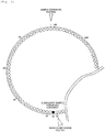
- Fig. 2 is a view schematically illustrating an arrangement example of the reaction container on the reaction disc.
- the reaction containers 104 are arranged side by side in a circumferential direction on the reaction disc 105.
- the reaction disc 105 is periodically rotated at equal angles so as to move the reaction containers 104 to a predetermined circumferential position. While the reaction disc 105 is stopped, the reagent dispensing mechanism 102 and the sample dispensing mechanism 103 which perform a dispensing process, and the washing mechanism 119 which performs a washing process can have access to the reaction container 104.
- the respective mechanisms perform various processes on the reaction container 104 which stops at an operable position. That is, the respective mechanisms periodically and repeatedly perform an operation corresponding to each process on the periodically moving reaction container 104, thereby causing an analysis process to move forward.
- Fig. 2 illustrates a state where 160 reaction containers 104 are arranged side by side in the circumferential direction (rotation direction) of the reaction disc 105.
- the reaction disc 105 is rotated so as to move a distance corresponding to 41 reaction containers while the reaction container 104 mounted on the reaction disc 105 is moved one round (hereinafter, referred to as a cycle)
- the sample dispensing operation is performed on the reaction container 104 of No. 42.
- the reaction container 104 of No. 1 returns again to the position for performing the sample dispensing process. That is, this process is similarly applied to the washing process performed by the washing mechanism 119.
- the washing process is first performed on the reaction container 104 of No. 43
- the washing process is performed on the reaction container 104 of No. 84 on the subsequent cycle.
- the washing process is performed again on the reaction container 104 of No. 43. This process is also applied to other processes.
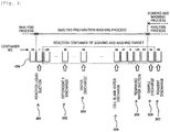
- Fig. 3 is a view illustrating an example of the washing process performed by the washing mechanism before an analysis of the reaction container.
- the washing process before the analysis of the reaction container 104 is configured to include multiple sub-processes. That is, the analysis preparation washing process is configured to include the multiple sub-processes such as a reaction liquid suction process, a detergent 1 discharge process, a water discharge process, a cell blank water discharge process, remaining water suction process, and multiple standby processes. Then, while the reaction disc 105 is stopped within one cycle, the washing mechanism 119 concurrently performs the process on the reaction containers 104 arriving at a reaction liquid suction position 301, a detergent 1 discharge position 302, a water discharge position 303, a cell blank water discharge position 304, and a remaining water suction position 305.
- the analysis preparation washing process is configured to include the multiple sub-processes such as a reaction liquid suction process, a detergent 1 discharge process, a water discharge process, a cell blank water discharge process, remaining water suction process, and multiple standby processes.
- the washing mechanism 119 concurrently performs the process on the reaction containers 104 arriving at a reaction liquid suction
- the reaction liquid suction process is a sub-process of performing a water discharge process at the reaction liquid suction position 301 by performing suction on the reaction liquid used for the previous analysis and discarding the reaction liquid as a waste liquid. For example, even in a case where those other than the reaction liquid such as water are contained in the reaction container 104, the water is similarly subjected to suction, and is discarded as the waste liquid. In this manner, the process of discharging the water is performed.
- the detergent 1 discharge process is a sub-process of discharging a detergent 1 by performing suction on the water discharged in the reaction liquid suction process at the detergent 1 discharge position 302.
- the water discharge process is a sub-process of discharging rinsing water by performing suction on the detergent 1 discharged in the detergent 1 discharge process at the water discharge position 303.
- the cell blank water discharge process is a sub-process of discharging water at the cell blank water discharge position 304 in order to measure a cell blank value.
- the remaining water suction process is a sub-process of performing suction on all water inside the reaction container 104 at the remaining water suction position 305 so as to remove remaining water for the subsequent analysis.
- the standby process is a sub-process of standing by without performing any special process on the reaction container 104 during a period between the respective sub-processes.
- the right side process in each process represents the subsequent process, and indicates that the process moves forward as each reaction container 104 moves to the right side. That is, each time the reaction disc 105 is rotated as much as a regulated angle on each cycle (that is, each time one cycle moves forward), the reaction container 104 subjected to washing at the respective positions 301 to 305 included in the washing mechanism 119 is located at a position of the reaction container 104 which is shifted one to the right in Fig. 3 . For example, on a cycle subsequent to the process in which the remaining water suction process is performed on the reaction container 104 of container No. 125 in Fig. 3 , the reaction container 104 of No. 6 arrives at the remaining water suction position 305, thereby performing the remaining water suction process.
- the respective reaction containers 104 can be used for the analysis after a series of analysis preparation washing processes is performed in the order of at least the reaction liquid suction process, the detergent 1 discharge process, the water discharge process, the cell blank water discharge process, and the remaining water suction process.
- the reaction container 104 of No. 1 is first moved to the reaction liquid suction position 301 in order to start the analysis after the washing process is first performed on the reaction container 104 of No. 1. Since the previous analysis process is completed, when the analysis start instruction is input, the sample is in a state where the sample is not dispensed to all of the reaction containers 104 mounted on the reaction disc 105. Except for a special case, in this state, the analysis start instruction is input. Thereafter, the reaction liquid suction process is performed on the reaction container of No. 1 so as to start periodical control for the reaction disc 105.
- the analysis preparation washing process a washing period after the washing process starts for the reaction container 104 of No. 1 before one cycle on which the reaction container 104 of No. 1 arrives at the sample discharge position 306 and the sample is dispensed.
- the analysis preparation washing process is performed.
- the number of cycles for the analysis preparation washing process is uniquely determined depending on the number of the reaction containers of the automatic analysis device 100, the sample dispensing mechanism 103 and the reaction liquid suction position 301 of the washing mechanism 119, and the number of the reaction containers operated on one cycle.
- an analyzing process (analysis process) for the sample is also configured to include multiple sub-processes. That is, the analysis process is configured to include the multiple sub-processes such as a sample discharge process, a reagent discharge process, and a measurement process (not illustrated).
- the sample discharge process is a sub-process of discharging an analysis target sample to the reaction container 104 which completes the analysis preparation washing process, at the sample discharge position 306.
- the reagent discharge process is a sub-process of discharging the reagent to the reaction container 104 from which the sample is discharged in the sample discharge process, at the reagent discharge position 307.
- the sample discharge process is a sub-process of discharging the sample to the reaction container 104 from which the reagent is discharged.
- the measurement process is a sub-process of measuring light absorbance of the reaction liquid when the reaction container 104 containing the reaction liquid in which the sample and the reagent are mixed with each other passes through a measurement position 308 (refer to Fig. 1 ) (or stops at the measurement position 308). Therefore, it is not always necessary to perform the measurement process while the reaction disc 105 is stopped.
- the reaction container 104 which completes all of the predetermined analysis preparation washing processes starting from the reaction liquid suction process, that is, the reaction container 104 for which washing is guaranteed in the analysis preparation washing process is allowed to start the analysis process. Therefore, when the analysis preparation washing process starts, the reaction container 104 (reaction container of No. 120 in Fig. 3 ) located at a position where one cycle moves forward from the reaction liquid suction position arrives at the sample discharge position earlier than the reaction container 104 (reaction container of No. 1 in Fig. 3 ) located at the reaction liquid suction position at the same time. However, the analysis process does not start.
- the soaking and washing are performed on the reaction container 104 arriving at the sample discharge position 306 earlier than the reaction container 104 for which the analysis process is first started.
- the soaking and washing are performed on the reaction container 104 arriving at the sample discharge position 306 in such a way that a soaking and washing detergent is discharged to the reaction container 104 by the sample dispensing mechanism 103.
- the reagent dispensing mechanism 102 may be configured to discharge the soaking and washing detergent.
- a configuration may be adopted in which other multiple dispensing mechanisms are prepared so as to discharge the soaking and washing detergent to the reaction container 104.
- the analysis preparation washing process starts.
- the soaking and washing detergent is discharged to the reaction container 104 of No. 43 in the order of the reaction container 104 of No. 84 by the sample dispensing mechanism 103(and the reagent dispensing mechanism 102).
- the reacn container 104 of No. 1 for which the analysis preparation washing process is completely performed by the washing mechanism 119 arrives at the sample discharge position 306, thereby dispensing the sample.
- the soaking and washing can be performed on the 38 reaction containers 104. That is, the reaction container 104 filled with the soaking and washing detergent is subjected to the soaking and washing within a period until the reaction container 104 arrives at the reaction liquid suction position 301.
- the reaction containers 104 can be soaked during 122 cycles. The washing process is performed on the reaction container 104 subjected to the soaking and washing by the washing mechanism 119, and the reaction container 104 is used for the analysis process.
- the control device 112 in a case where an operator inputs the analysis start (return from a stopped state, or analysis start due to the return from a standby state) instruction, that is, in a state where the sample is not dispensed to all of the reaction containers 104 mounted on the reaction disc 105, the control device 112 is configured to include the analysis preparation washing process of washing the reaction containers 104 immediately before the reaction containers 104 is used for the analysis process, and the multiple sub-processes provided so as to partially overlap the analysis process, and includes a leading sub-process of dispensing the soaking and washing detergent to the reaction container 104.
- the control device 112 controls the soaking and washing process of performing the soaking and washing during a predetermined period of time by dispensing the soaking and washing detergent to the reaction container 104 so that all of these processes concurrently start.
- the control device 112 controls the soaking and washing process for performing the soaking and washing during a predetermined period of time to be started by dispensing the soaking and washing detergent to another reaction container different from the reaction container.
- the soaking and washing detergent in the soaking and washing process is discharged to the reaction container 104 on which the analysis preparation washing process is first performed, while the minimum number of cycles required for completing the washing process move forward. Therefore, the soaking and washing can be performed on some of the reaction containers 104 without a need to provide a time for new soaking and washing which is required due to the increased number of cycles.
- the analysis preparation washing process of the reaction container 104 which is first subjected to the analysis preparation washing and the soaking and washing process of the reaction container 104 which is first subjected to the soaking and washing it is not always necessary to concurrently start the analysis preparation washing process of the reaction container 104 which is first subjected to the analysis preparation washing and the soaking and washing process of the reaction container 104 which is first subjected to the soaking and washing.
- the start of the soaking and washing process of the reaction container 104 which is first subjected to the soaking and washing may be delayed as much as one cycle than the start of the analysis preparation washing process of the reaction container 104 which is first subjected to the analysis preparation washing. Even in this case, the soaking and washing can be performed on 37 reaction containers 104.
- the soaking and washing detergent is discharged by the sample dispensing mechanism 103 or the reagent dispensing mechanism 102.
- the invention is not limited thereto.
- a new dispensing mechanism for discharging a dischargeable soaking and washing detergent may be disposed at a position where the reaction container 104 passing through the dispensing position in the dispensing mechanisms arrives.
- the new dispensing mechanism is added and the soaking time is shortened, the invention is applicable to this method. In this case, the number of cycles increases until the reaction container 104 for which the analysis preparation washing process is first started arrives at the dispensing position of the dedicated dispensing mechanism.
- the soaking and washing detergent can be dispensed to the reaction containers 104 as much as possible without affecting the analysis process start.
- the sample dispensing mechanism 103 before the analysis preparation washing process of the reaction container to be used in analyzing the sample to be first analyzed is completely performed, the sample dispensing mechanism 103 continues to dispense the soaking and washing detergent. After the analysis preparation washing process is completely performed, the sample dispensing mechanism 103 continues to dispense the sample for analysis.
- the reagent dispensing mechanism 102 in a case where the soaking and washing detergent is dispensed by the reagent dispensing mechanism 102, similarly to a case where the sample is replaced with the reagent, before the analysis preparation washing process is completely performed, the reagent dispensing mechanism 102 continues to dispense the soaking and washing detergent. After the process is completely performed, the reagent dispensing mechanism 102 continues to dispense the reagent for analysis.
- the number of the reaction containers 104 which can be subjected to the soaking and washing depends on a cycle of the analysis preparation washing process.
- the multiple reaction containers 104 mounted on the reaction disc 105 are divided into a block (reaction container group) configured to include the number of the reaction containers 104 which can be subjected to the soaking and washing once.
- the soaking and washing are performed on each block. For example, in a case where the number of the reaction containers 104 which can be subjected to soaking once is 38 within 160 reaction containers in total, the reaction containers can be divided into at least 5 blocks.
- the reaction containers can be divided into the number of blocks corresponding to the quotient of N/M.
- the number of cycles applied to the analysis preparation washing process corresponds to the maximum number of the reaction containers subjected to the soaking and washing. Accordingly, if the number of cycles is set to L (M ⁇ L) (L is a natural number), the number corresponding to the quotient of N/L represents the minimum number of blocks.
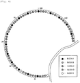
- Fig. 4 is a view illustrating an example of block division of the reaction containers.
- Fig. 4 illustrates a case where the multiple reaction containers 104 arranged on the reaction disc 105 are divided into Block A to Block D as the reaction container group configured to include 38 reaction containers 104, and divided into Block E as the reaction container group configured to include 8 reaction containers 104.
- Block A is obtained by defining the total 38 reaction containers as one reaction container group in the order of using the reaction containers 104 which are determined by the rotation of the reaction disc, starting from the reaction container of No. 1 as a leading reaction container 104.
- Block B is obtained by defining the total 38 reaction containers as one reaction container group in the order of using the reaction containers 104 starting from the reaction container of No. 119 to be used the 39 th time as a leading reaction container 104. This is similarly applied to Block C, Block D, and Block E.
- the reaction container 104 of No. 1 when a certain analysis starts, and the reaction containers 104 of No. 119, No. 77, No. 35, and No. 153 when the subsequent analysis starts are respectively controlled so as to move to the sample discharge position 306 before the analysis preparation washing starts. In this manner, the soaking and washing can be sequentially performed on all of the reaction containers 104.
- another block different from the block subjected to the previous soaking and washing may be washed whenever the analysis starts.
- the leading reaction container 104 of the block for performing the soaking and washing may be moved to the sample discharge position 306.
- the analysis preparation washing may be performed after the reaction container of No. 1 is moved to the sample discharge position 306.
- the reaction disc 105 is controlled in this way.
- the soaking and washing can be performed on every one block a day.
- all of the blocks can be completely washed within 5 days, and the soaking and washing are performed again on the first block from the 6 th day.
- the soaking and washing can be performed on the reaction containers on a cycle of 5 days. Therefore, it is not necessary to individually spend the time for periodical maintenance.
- the reaction container 104 belonging to one block may not be fixed.
- 8 reaction containers 104 are present in Block E.
- a configuration may be adopted in which 30 reaction containers 104 from the leading reaction container of Block A may be washed in accordance with the washing of Block E.
- This case has the same configuration as a case where the date and time of the previous washing are stored for each reaction container 104, and where a new block is configured to include the block having 38 reaction containers from the reaction container having the oldest date and time of the previous washing within all of the reaction containers.
- the number of reaction containers in one block and the number of blocks may not be fixed.
- an analysis device including 160 reaction containers 104 may be configured to include 5 blocks having 32 reaction containers 104 per block.
- the analysis device may have 6 blocks, and each block may be configured to include 26 or 27 reaction containers 104. It is desirable that the number of reaction containers 104 belonging to each block falls within the number of cycles of the analysis preparation washing (38 cycles in the present embodiment). The reason is that the soaking and washing can be performed without providing a time for new soaking and washing which are needed due to the increased number of cycles.
- the soaking and washing process is not limited to the process performed when the analysis starts from standby.
- the analysis device in a case of completing the analysis relating to all of the samples conveyed to the analysis device, the analysis device is in a standby state until a new sample is conveyed. Accordingly, it is also considered that the soaking and washing are performed on the reaction container immediately after the analysis device is brought into the standby state.
- the storage device 118 may store information indicating whether or not the reaction liquid remains in all of the reaction containers 104, and may control the soaking and washing to be performed if there is no reaction container in which the reaction liquid remains in the soaking and washing target reaction container group.
- the reaction container 104 in which the remaining liquid is finally subjected to suction is contained in the soaking and washing target reaction container group, there is a possibility that the reaction liquid may remain in the soaking and washing target reaction container group. Accordingly, the soaking and washing are not performed at that time.
- the soaking and washing are not performed. In these cases, the soaking and washing are performed when the subsequent analysis starts. Alternatively, in a case where there is the remaining liquid in the soaking and washing target reaction container group, the remaining liquid may be discarded after the analysis starts. Thereafter, the soaking and washing may be performed without using the corresponding reaction container 104 for the analysis.
- the analysis may start after the device is necessarily provided with the sufficient detergent by warning a user to add the detergent thereto.
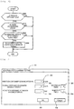
- Fig. 5 is a flowchart illustrating the soaking and washing process.
- Fig. 6 is a flowchart illustrating a process of specifying a soaking and washing target block.
- control device 112 If an operator inputs an analysis start instruction, the control device 112 first performs the process of specifying the soaking and washing target blocks (to be described later)
- Step S110 the reaction container 104 whose use order is earliest is moved to the sample discharge position 306 (Step S110).
- the reaction container 104 whose use order is earliest within the determined block is the reaction container 104 of No. 119, and becomes a soaking and washing target container. If the time from the analysis start instruction until when the process (to be described later) starts is short, the analysis process starts early. Accordingly, the movement operation in Step S110 is a movement independent of the rotation stopping operation on one cycle of the reaction disc in the analysis preparation washing process. That is, in this case, the reaction container 104 of No. 119 is efficiently moved to the sample discharge position 306 without stopping at a position other than the sample discharge position 306.
- Step S120 and S125 the analysis preparation washing process and a soaking detergent discharge process are concurrently performed.
- the rotation stopping operation of the reaction disc is repeatedly performed on every one cycle, thereby performing the processes. It is determined whether or not the soaking detergent is completely discharged to all of the reaction containers 104 in the soaking and washing target block (Step S130). In a case where the determination result is NO in Step S130, the processes in Steps S120 and S125 are repeatedly performed until the soaking detergent is completely discharged to all of the reaction containers 104 in the soaking and washing target block.
- Step S140 the analysis control is performed (Step S140).
- the sample is dispensed to the reaction container 104 arriving at the sample discharge position 306, and the reagent is dispensed to the reaction container 104 arriving at the reagent discharge position 307. Since the used reaction container 104 is washed and reused, the washing mechanism 119 continuously performs the washing process even during the analysis control.
- Step S150 it is determined whether or not the analysis request is all completed. In a case where the determination result is NO, the process in Step S140 is repeatedly performed until the determination result shows YES.
- Step S150 In addition, in a case where the determination result is YES in Step S150, all of the reaction containers are washed in order to bring all of the reaction containers into a state where the sample is not dispensed. A completing process is performed (Step S160), thereby completing the process by stopping the overall control.
- the processes are performed in accordance with the flow from Step S100 of specifying the soaking and washing target block. That is, after the new analysis start instruction is input, the control device 112 conveys one reaction container in the reaction container group which is not the target for performing the previous soaking and washing process, to the position for dispensing the soaking and washing detergent, thereby starting the soaking and washing process. In addition, at this time, the reaction container is conveyed independently of the rotation stopping operation on one cycle of the reaction disc in the analysis preparation washing process.
- the above-described control is repeatedly performed with the analysis start as a trigger. Accordingly, if attention is paid to one reaction container, while the soaking and washing process is performed twice, the reaction container is brought into either a state where the soaking and washing are completely performed on all of the reaction containers mounted on the reaction disc or a state where the soaking and washing process starts. Therefore, the soaking and washing can be equally performed on all of the reaction containers.
- a cell blank value functioning as a reference value may be subsequently measured, and the measured cell blank value may be stored in the storage device 118 of the device.
- each dispensing mechanism may be washed in accordance with the soaking and washing of the reaction container.
- Each probe can be sufficiently washed within a time shorter than the soaking and washing time of the reaction container. Accordingly, if the maximum number of soaking available reaction containers is set to Na, the number of the reaction containers in the washing target block is set to Nb, and the number of washing times for the dispensing mechanism is set to Nc, the washing can be performed in a case of Na ⁇ Nb+Nc.
- the maximum number of soaking available reaction containers represents the number of reaction containers which can be subjected to the soaking and washing by single analysis start, and is 38 in the example in Fig. 2 .
- the dispensing mechanism can also be washed in accordance with the soaking and washing of Block E.
- the control device 112 performs a mechanism resetting operation, and thereafter, determines whether or not a preset fixed period of time Ta elapses at a washing interval T (Step S200). In a case where the determination result is NO, the control device 112 determines that there is no block in which the fixed period of time elapses and the soaking and washing are not needed, thereby completing the process.
- Step S200 the control device 112 determines that there is a block in which the fixed period of time elapses, and determines whether or not the remaining liquid is absent in the block subjected to the soaking and washing in the most past within the target blocks (Step S210). In a case where the determination result is NO in Step S210, the control device 112 determines that the soaking and washing cannot be performed, thereby completing the process.
- Step S210 the control device 112 determines whether or not the amount of the soaking detergent is sufficient (Step S220). In a case where the determination result is NO, the control device 112 determines that the soaking and washing cannot be performed, thereby completing the process.
- Step S220 the control device 112 determines that the reaction container 104 whose use order is earliest in the block determined in Step S200 is the reaction container 104 to be moved to the sample discharge position 306 as the soaking and washing target container.
- Step S200 is not limited to the date and time of the previous washing.
- a method may be employed in which the number of dispensing times of the reagent containing a predetermined component is stored so that the block including the reaction container where the number of dispensing times is equal to or greater than a predetermined number of times is selected as a washing target.
- Fig. 7 is a view illustrating an example of a screen for setting a washing interval of the reaction container and each probe.
- a reaction system washing setting screen 701 includes a washing interval input area 702 which sets an interval for performing the soaking and washing of the reaction container 104.
- the reaction system washing setting screen 701 includes washing interval input areas 703 and 704 which respectively set each washing interval of the sample dispensing mechanism 103 and the reagent dispensing mechanism 102, washing number input areas 705 and 706 which respectively set each number of washing times, an OK button 707 which determines an input setting value, and a cancellation button 708 which cancels the input setting value.
- a unit of the washing interval of the reaction container is a day. However, the unit may be the number of use times of each reaction container 104 or the number of rounds.
- the number of rounds is a value obtained in such a way that a cycle on which the reaction container 104 of No. 1 arrives at the sample dispensing position and subsequently arrives at the sample dispensing position after the sample is dispensed is counted as one round.
- the soaking and washing can be provided in accordance with a frequency of using the device for every facility.
- Fig. 8 is a view illustrating another example of a screen for setting a washing interval of the reaction container.
- a washing setting screen 801 includes a block area 802 which displays a block name, a container number input area 803 which inputs the number of soaking and washing target reaction containers in each block, a day-of-week input area 804 which inputs the day of week for performing the soaking and washing on each block, an OK button 805 which determines an input setting value, and a cancellation button 806 which cancels the input setting value.
- the washing setting screen 801 represents a case where the soaking and washing interval of the reaction container 104 is set to one week. For example, in a case where the reaction containers are divided into blocks as illustrated in Fig.
- Block A Block E as illustrated in Fig. 8 .
- Fig. 9 is a view illustrating an example of a washing state display screen for displaying a washing state of the reaction container and each probe.
- a washing state display screen 901 has a washing state display area 902 which displays a washing state of each reaction container, a cell blank value display area 903 which displays a cell blank value of the reaction container (for example, the reaction container of No. 6) selected by the washing state display area 902, a washing state display area 904 which displays a washing state of the sample dispensing mechanism 103, and a washing state display area 905 which displays a washing state of the reagent dispensing mechanism 102.
- the washing state display area 902 displays a number of each reaction container 106 and the date when the previous soaking and washing are performed. In a case where a unit of the washing interval of the reaction container 104 is set to the number of use times or the number of rounds, the number of use times or the number of rounds from when the previous washing is performed may be displayed.
- the cell blank value display area 903 displays the reaction container 106 selected by the washing state display area 902 in such a way that the date when the soaking and washing are performed and the cell blank value is measured and the cell blank value of each wavelength are retroactively applied to several times in the past. A change in the cell blank value enables a user to confirm an advantageous effect of the soaking and washing.
- the operator checks an additional washing setting check box 902a disposed for each reaction container in the washing state display area 902.
- the soaking and washing can be additionally performed on only a specified reaction container. That is, the soaking and washing are performed on the reaction container 104 in which the additional washing setting check box 902a is checked, prior to the analysis in the reaction container during the analysis.
- the check box 902a may not be provided.
- a configuration may be adopted in which the reaction container is automatically selected as the soaking and washing target in a case where deviation in a certain level or greater is present between the predetermined reference value of the cell blank value and the cell blank value measured this time.
- the present embodiment adopts the following configuration. After the analysis start instruction is input in a state where the sample is not dispensed to all of reaction containers mounted on the reaction disc, before completing the analysis preparation washing process for washing the reaction container to be used in analyzing the sample to be first analyzed, the soaking and washing process for performing soaking and washing during a predetermined period of time is controlled to be started by dispensing the soaking and washing detergent to another reaction container different from the reaction container. Therefore, the soaking and washing can be efficiently performed on the reaction container without hindering the analysis process.
Landscapes
- Chemical & Material Sciences (AREA)
- Health & Medical Sciences (AREA)
- General Physics & Mathematics (AREA)
- Physics & Mathematics (AREA)
- Life Sciences & Earth Sciences (AREA)
- Analytical Chemistry (AREA)
- Biochemistry (AREA)
- General Health & Medical Sciences (AREA)
- Immunology (AREA)
- Pathology (AREA)
- Chemical Kinetics & Catalysis (AREA)
- Clinical Laboratory Science (AREA)
- Medicinal Chemistry (AREA)
- Automatic Analysis And Handling Materials Therefor (AREA)
- Sampling And Sample Adjustment (AREA)
Abstract
Description
- The present invention relates to an automatic analysis device which performs quantitative and qualitative analyses on a biological sample such as blood and urine.
- An automatic analysis device has a washing mechanism and a washing tank which wash a reaction container for mixing a sample and a reagent or a probe used in dispensing by using water or a predetermined detergent, immediately before use. The automatic analysis device aims to prevent analysis accuracy from being degraded due to dirt adhering to the reaction container or the probe. However, blood or urine as an analysis target sample contains proteins and lipids. Thus, the automatic analysis device is in a situation where the dirt is likely to adhere to the reaction container or the probe. In addition, since the reaction container or the probe is repeatedly used, it is difficult to remove the adhering dirt by only performing washing immediately before.
- Therefore, for example, the dirt adhering to the reaction container or the probe is removed by periodically performing maintenance in which the inside of the reaction container or the probe is soaked in a high concentration detergent for a fixed period of time. For example, PTL 1 (
JP-A-2008-281454 - PTL 1:
JP-A-2008-281454 - Incidentally, in facilities in which an automatic analysis device is always operated for 24 hours in preparation for urgent sample arrival, even if soaking and washing are performed during standby as in the related art, in a case where an urgent sample analysis is needed, the soaking and washing have to be stopped, and there is no guarantee that a time for soaking can be sufficiently secured. In addition, if an operator tries to forcibly complete the soaking and washing, it is considered that an analysis process is hindered, thereby causing a possibility of degraded analysis efficiency.
- The present invention is made in view of the above-described circumstances, and an object thereof is to provide an automatic analysis device which can efficiently perform soaking and washing on a reaction container without hindering an analysis process.
- In order to achieve the above-described object, according to the invention, there is provided an automatic analysis device including a sample container conveyance path that conveys multiple sample containers containing a sample as an analysis target, a reagent disc on which multiple reagent containers containing a reagent for use in analyzing the sample are mounted, a reaction disc that arranges multiple reaction containers for mixed reaction between the sample and the reagent so as to be side by side in a circumferential direction, and that conveys the reaction container, a sample dispensing mechanism that dispenses the sample to the reaction container of the reaction disc from the sample container, a reagent dispensing mechanism that dispenses the reagent to the reaction container of the reaction disc from the reagent container of the reagent disc, and a control device that controls a soaking and washing process for performing soaking and washing during a predetermined period of time to be started by dispensing a soaking and washing detergent to another reaction container different from the reaction container, after an analysis start instruction is input in a state where the sample is not dispensed to all of the reaction containers mounted on the reaction disc, before completing an analysis preparation washing process for washing the reaction container to be used in analyzing the sample to be first analyzed.
- According to the present invention, soaking and washing can be efficiently performed on a reaction container without hindering an analysis process.
-
- [
Fig. 1] Fig. 1 is a view schematically illustrating a configuration of an automatic analysis device according to an embodiment of the invention. - [
Fig. 2] Fig. 2 is a view schematically illustrating an arrangement example of a reaction container on a reaction disc. - [
Fig. 3] Fig. 3 is a view illustrating an example of a washing process performed by a washing mechanism before an analysis of the reaction container. - [
Fig. 4] Fig. 4 is a view illustrating an example of block division of the reaction containers. - [
Fig. 5] Fig. 5 is a flowchart illustrating a soaking and washing process. - [
Fig. 6] Fig. 6 is a flowchart illustrating a process of specifying a soaking and washing target block. - [
Fig. 7] Fig. 7 is a view illustrating an example of a screen for setting a washing interval of the reaction container and each probe. - [
Fig. 8] Fig. 8 is a view illustrating another example of a screen for setting a washing interval of the reaction container. - [
Fig. 9] Fig. 9 is a view illustrating an example of a washing state display screen for displaying a washing state of the reaction container and each probe. - An embodiment of the invention will be described with reference to the drawings.
-
Fig. 1 is a view schematically illustrating a configuration of an automatic analysis device according to the embodiment of the invention. - In
Fig. 1 , anautomatic analysis device 100 schematically includes a samplecontainer conveyance path 116 that conveys asample container rack 115 on which asample container 117 for containing a biological sample (hereinafter, simply referred to as a sample) such as blood and urine which are quantitative and qualitative analysis targets is mounted, areagent disc 101 on whichmultiple reagent containers 110 for containing a reagent used in analyzing the sample are mounted, areaction disc 105 that arrangesmultiple reaction containers 104 for mixed reaction between the sample and the reagent so as to be side by side in a circumferential direction, and that conveys thereaction container 104, asample dispensing mechanism 103 that dispenses the sample to thereaction container 104 of thereaction disc 105 from thesample container 117 conveyed to asample dispensing position 108 by the samplecontainer conveyance path 116, areagent dispensing mechanism 102 that dispenses the reagent to thereaction container 104 of thereaction disc 105 from thereagent container 110 of thereagent disc 101, and acontrol device 112 that controls an operation of amulti-wavelength photometer 106 for measuring light obtained from alight source 106a via thereaction container 104 and the overallautomatic analysis device 100. - The
sample container rack 115 having thesample container 117 mounted thereon is conveyed to thesample dispensing position 108 by the samplecontainer conveyance path 116. The sample contained in thesample container 117 is subjected to suction by thesample dispensing mechanism 103. A predetermined amount of the sample is dispensed into thereaction container 104 arranged in thereaction disc 105. - The
reaction container 104 to which the sample is discharged is moved to a reagent adding position by thereaction disc 105 whose temperature is controlled after communicating with athermostatic tank 109. At this time, thereagent disc 101 performs a rotary operation so as to move thereagent container 110 corresponding to an analysis item to below thereagent dispensing mechanism 102. Then, a predetermined amount of the reagent subjected to suction from thereagent container 110 is dispensed to thereaction container 104 moved to the reagent adding position by thereagent dispensing mechanism 102. After the reagent is dispensed, thereaction container 104 is moved to a position of amixing device 111 so as to perform initial mixing. - A light beam emitted from the
light source 106a passes through thereaction container 104 in which the dispensed sample and reagent are mixed with each other, and is incident on themulti-wavelength photometer 106. In this manner, light absorbance of a reaction liquid which is content of thereaction container 104 is detected by themulti-wavelength photometer 106. A detected light absorbance signal is transmitted to thecontrol device 112 via analog / digital (A/D)converter 107 and an interface (not illustrated). The light absorbance signal (that is, a measurement value) transmitted to thecontrol device 112 is converted into analysis item concentration of a measurement target in the sample, is displayed on adisplay input unit 114 disposed in thecontrol device 112, and is stored in astorage device 118 disposed in thecontrol device 112. - The
display input unit 114 is a graphic user interface (GUI) for displaying an analysis result or an operation screen. In a state where the operation screen is displayed, a button displayed on the operation screen is clicked by using a mouse pointer. In this manner, various operations and settings can be performed in theautomatic analysis device 100. - The
reaction container 104 in which the contained reaction liquid is completely measured is moved to a position of awashing mechanism 119. After a liquid (reaction liquid) contained therein is subjected to suction and washing (to be described in detail later), thereaction container 104 is provided for the subsequent analysis. -
Fig. 2 is a view schematically illustrating an arrangement example of the reaction container on the reaction disc. - As illustrated in
Fig. 2 , thereaction containers 104 are arranged side by side in a circumferential direction on thereaction disc 105. Thereaction disc 105 is periodically rotated at equal angles so as to move thereaction containers 104 to a predetermined circumferential position. While thereaction disc 105 is stopped, thereagent dispensing mechanism 102 and thesample dispensing mechanism 103 which perform a dispensing process, and thewashing mechanism 119 which performs a washing process can have access to thereaction container 104. The respective mechanisms perform various processes on thereaction container 104 which stops at an operable position. That is, the respective mechanisms periodically and repeatedly perform an operation corresponding to each process on the periodically movingreaction container 104, thereby causing an analysis process to move forward. - For example,
Fig. 2 illustrates a state where 160reaction containers 104 are arranged side by side in the circumferential direction (rotation direction) of thereaction disc 105. For example, if it is assumed that thereaction disc 105 is rotated so as to move a distance corresponding to 41 reaction containers while thereaction container 104 mounted on thereaction disc 105 is moved one round (hereinafter, referred to as a cycle), in a cycle subsequent to the cycle in which the sample dispensing process is performed on thereaction container 104 of No. 1, the sample dispensing operation is performed on thereaction container 104 of No. 42. In addition, if thereaction container 104 is moved on 160 cycles which are the same as the total number of thereaction containers 104 mounted on thereaction disc 105, thereaction container 104 of No. 1 returns again to the position for performing the sample dispensing process. That is, this process is similarly applied to the washing process performed by thewashing mechanism 119. In a case where the washing process is first performed on thereaction container 104 of No. 43, the washing process is performed on thereaction container 104 of No. 84 on the subsequent cycle. After 160 cycles, the washing process is performed again on thereaction container 104 of No. 43. This process is also applied to other processes. -
Fig. 3 is a view illustrating an example of the washing process performed by the washing mechanism before an analysis of the reaction container. - As illustrated in
Fig. 3 , the washing process before the analysis of the reaction container 104 (analysis preparation washing process) is configured to include multiple sub-processes. That is, the analysis preparation washing process is configured to include the multiple sub-processes such as a reaction liquid suction process, adetergent 1 discharge process, a water discharge process, a cell blank water discharge process, remaining water suction process, and multiple standby processes. Then, while thereaction disc 105 is stopped within one cycle, thewashing mechanism 119 concurrently performs the process on thereaction containers 104 arriving at a reactionliquid suction position 301, adetergent 1discharge position 302, awater discharge position 303, a cell blankwater discharge position 304, and a remainingwater suction position 305. - The reaction liquid suction process is a sub-process of performing a water discharge process at the reaction
liquid suction position 301 by performing suction on the reaction liquid used for the previous analysis and discarding the reaction liquid as a waste liquid. For example, even in a case where those other than the reaction liquid such as water are contained in thereaction container 104, the water is similarly subjected to suction, and is discarded as the waste liquid. In this manner, the process of discharging the water is performed. - The
detergent 1 discharge process is a sub-process of discharging adetergent 1 by performing suction on the water discharged in the reaction liquid suction process at thedetergent 1discharge position 302. - The water discharge process is a sub-process of discharging rinsing water by performing suction on the
detergent 1 discharged in thedetergent 1 discharge process at thewater discharge position 303. - The cell blank water discharge process is a sub-process of discharging water at the cell blank
water discharge position 304 in order to measure a cell blank value. - The remaining water suction process is a sub-process of performing suction on all water inside the
reaction container 104 at the remainingwater suction position 305 so as to remove remaining water for the subsequent analysis. - The standby process is a sub-process of standing by without performing any special process on the
reaction container 104 during a period between the respective sub-processes. - In
Fig. 3 , the right side process in each process represents the subsequent process, and indicates that the process moves forward as eachreaction container 104 moves to the right side. That is, each time thereaction disc 105 is rotated as much as a regulated angle on each cycle (that is, each time one cycle moves forward), thereaction container 104 subjected to washing at therespective positions 301 to 305 included in thewashing mechanism 119 is located at a position of thereaction container 104 which is shifted one to the right inFig. 3 . For example, on a cycle subsequent to the process in which the remaining water suction process is performed on thereaction container 104 of container No. 125 inFig. 3 , thereaction container 104 of No. 6 arrives at the remainingwater suction position 305, thereby performing the remaining water suction process. - Then, the
respective reaction containers 104 can be used for the analysis after a series of analysis preparation washing processes is performed in the order of at least the reaction liquid suction process, thedetergent 1 discharge process, the water discharge process, the cell blank water discharge process, and the remaining water suction process. - For example, in a case where setting is made so that the
reaction container 104 of No. 1 is first used for an analysis process, if an analysis start instruction is input by an operator pressing down a start button, thereaction container 104 of No. 1 is first moved to the reactionliquid suction position 301 in order to start the analysis after the washing process is first performed on thereaction container 104 of No. 1. Since the previous analysis process is completed, when the analysis start instruction is input, the sample is in a state where the sample is not dispensed to all of thereaction containers 104 mounted on thereaction disc 105. Except for a special case, in this state, the analysis start instruction is input. Thereafter, the reaction liquid suction process is performed on the reaction container of No. 1 so as to start periodical control for thereaction disc 105. While the reaction container of No. 1 arrives at thesample discharge position 306 from when the washing starts, since the reaction container which can be analyzed is not present, the sample is caused to stand by for the sample dispensing. Hereinafter, a washing period after the washing process starts for thereaction container 104 of No. 1 before one cycle on which thereaction container 104 of No. 1 arrives at thesample discharge position 306 and the sample is dispensed is referred to as the analysis preparation washing process. In some cases, the reagent is dispensed earlier than the sample. Accordingly, in this case, during the washing period before one cycle on which the reagent is dispensed, the analysis preparation washing process is performed. In this example, a case is described where 38 cycles are needed to completely perform the analysis preparation washing process on thereaction container 104. The number of cycles for the analysis preparation washing process is uniquely determined depending on the number of the reaction containers of theautomatic analysis device 100, thesample dispensing mechanism 103 and the reactionliquid suction position 301 of thewashing mechanism 119, and the number of the reaction containers operated on one cycle. - In addition, as partially illustrated in
Fig. 3 , an analyzing process (analysis process) for the sample is also configured to include multiple sub-processes. That is, the analysis process is configured to include the multiple sub-processes such as a sample discharge process, a reagent discharge process, and a measurement process (not illustrated). - The sample discharge process is a sub-process of discharging an analysis target sample to the
reaction container 104 which completes the analysis preparation washing process, at thesample discharge position 306. - The reagent discharge process is a sub-process of discharging the reagent to the
reaction container 104 from which the sample is discharged in the sample discharge process, at thereagent discharge position 307. In a case where the reagent is discharged earlier, the sample discharge process is a sub-process of discharging the sample to thereaction container 104 from which the reagent is discharged. - The measurement process is a sub-process of measuring light absorbance of the reaction liquid when the
reaction container 104 containing the reaction liquid in which the sample and the reagent are mixed with each other passes through a measurement position 308 (refer toFig. 1 ) (or stops at the measurement position 308). Therefore, it is not always necessary to perform the measurement process while thereaction disc 105 is stopped. - Next, the soaking and washing will be described. In the analysis process, the
reaction container 104 which completes all of the predetermined analysis preparation washing processes starting from the reaction liquid suction process, that is, thereaction container 104 for which washing is guaranteed in the analysis preparation washing process is allowed to start the analysis process. Therefore, when the analysis preparation washing process starts, the reaction container 104 (reaction container of No. 120 inFig. 3 ) located at a position where one cycle moves forward from the reaction liquid suction position arrives at the sample discharge position earlier than the reaction container 104 (reaction container of No. 1 inFig. 3 ) located at the reaction liquid suction position at the same time. However, the analysis process does not start. According to the present embodiment, in parallel with the analysis preparation washing which causes the sample dispensing to stand by, the soaking and washing are performed on thereaction container 104 arriving at thesample discharge position 306 earlier than thereaction container 104 for which the analysis process is first started. The soaking and washing are performed on thereaction container 104 arriving at thesample discharge position 306 in such a way that a soaking and washing detergent is discharged to thereaction container 104 by thesample dispensing mechanism 103. In addition, in a case where a dispensing amount of thesample dispensing mechanism 103 is not sufficient in discharging the soaking and washing detergent, thereagent dispensing mechanism 102 may be configured to discharge the soaking and washing detergent. Alternatively, a configuration may be adopted in which other multiple dispensing mechanisms are prepared so as to discharge the soaking and washing detergent to thereaction container 104. - In the example illustrated in
Fig. 3 , the analysis preparation washing process starts. In parallel to the washing process performed by thewashing mechanism 119 in the order of thereaction container 104 of No. 1 and thereaction container 104 of No. 42, the soaking and washing detergent is discharged to thereaction container 104 of No. 43 in the order of thereaction container 104 of No. 84 by the sample dispensing mechanism 103(and the reagent dispensing mechanism 102). After the number of processes (38 cycles) required for completing the analysis preparation washing process according to the present embodiment, on a cycle subsequent to the cycle where the soaking and washing detergent is completely discharged to thereaction container 104 of No. 120, thereacn container 104 of No. 1 for which the analysis preparation washing process is completely performed by thewashing mechanism 119 arrives at thesample discharge position 306, thereby dispensing the sample. - In this way, during the analysis preparation washing on 38 cycles, 38 reaction containers arrive at the
sample discharge position 306. Accordingly, the soaking and washing can be performed on the 38reaction containers 104. That is, thereaction container 104 filled with the soaking and washing detergent is subjected to the soaking and washing within a period until thereaction container 104 arrives at the reactionliquid suction position 301. As in this example, according to the analysis device including 160reaction containers 104 so as to perform the analysis preparation washing on 38 cycles, thereaction containers 104 can be soaked during 122 cycles. The washing process is performed on thereaction container 104 subjected to the soaking and washing by thewashing mechanism 119, and thereaction container 104 is used for the analysis process. - In other words, according to the present embodiment, in a case where an operator inputs the analysis start (return from a stopped state, or analysis start due to the return from a standby state) instruction, that is, in a state where the sample is not dispensed to all of the
reaction containers 104 mounted on thereaction disc 105, thecontrol device 112 is configured to include the analysis preparation washing process of washing thereaction containers 104 immediately before thereaction containers 104 is used for the analysis process, and the multiple sub-processes provided so as to partially overlap the analysis process, and includes a leading sub-process of dispensing the soaking and washing detergent to thereaction container 104. Thecontrol device 112 controls the soaking and washing process of performing the soaking and washing during a predetermined period of time by dispensing the soaking and washing detergent to thereaction container 104 so that all of these processes concurrently start. - In other words, after the analysis start instruction is input in a state where the sample is not dispensed to all of the
reaction containers 104 mounted on the reaction disc, before the analysis preparation washing process of washing the reaction container to be used in analyzing the sample to be first analyzed is completely performed, thecontrol device 112 controls the soaking and washing process for performing the soaking and washing during a predetermined period of time to be started by dispensing the soaking and washing detergent to another reaction container different from the reaction container. - According to this control, the soaking and washing detergent in the soaking and washing process is discharged to the
reaction container 104 on which the analysis preparation washing process is first performed, while the minimum number of cycles required for completing the washing process move forward. Therefore, the soaking and washing can be performed on some of thereaction containers 104 without a need to provide a time for new soaking and washing which is required due to the increased number of cycles. - However, according to the invention, it is not always necessary to concurrently start the analysis preparation washing process of the
reaction container 104 which is first subjected to the analysis preparation washing and the soaking and washing process of thereaction container 104 which is first subjected to the soaking and washing. In a case of the above-described example, an example has been described in which the soaking and washing are performed on 38reaction containers 104. However, the start of the soaking and washing process of thereaction container 104 which is first subjected to the soaking and washing may be delayed as much as one cycle than the start of the analysis preparation washing process of thereaction container 104 which is first subjected to the analysis preparation washing. Even in this case, the soaking and washing can be performed on 37reaction containers 104. However, in viewpoint of performing the soaking and washing on thereaction containers 104 as much as possible, it is desirable to concurrently start these processes for thereaction container 104 which is first subjected to the washing. - In addition, in the above-described example, the soaking and washing detergent is discharged by the
sample dispensing mechanism 103 or thereagent dispensing mechanism 102. However, the invention is not limited thereto. A new dispensing mechanism for discharging a dischargeable soaking and washing detergent may be disposed at a position where thereaction container 104 passing through the dispensing position in the dispensing mechanisms arrives. In this case, although the new dispensing mechanism is added and the soaking time is shortened, the invention is applicable to this method. In this case, the number of cycles increases until thereaction container 104 for which the analysis preparation washing process is first started arrives at the dispensing position of the dedicated dispensing mechanism. Accordingly, the soaking and washing detergent can be dispensed to thereaction containers 104 as much as possible without affecting the analysis process start. However, it is desirable to adopt the above-described example in a viewpoint that the new dispensing mechanism is not needed and the longer soaking time is ensured. - According to the above-described example, before the analysis preparation washing process of the reaction container to be used in analyzing the sample to be first analyzed is completely performed, the
sample dispensing mechanism 103 continues to dispense the soaking and washing detergent. After the analysis preparation washing process is completely performed, thesample dispensing mechanism 103 continues to dispense the sample for analysis. In addition, in a case where the soaking and washing detergent is dispensed by thereagent dispensing mechanism 102, similarly to a case where the sample is replaced with the reagent, before the analysis preparation washing process is completely performed, thereagent dispensing mechanism 102 continues to dispense the soaking and washing detergent. After the process is completely performed, thereagent dispensing mechanism 102 continues to dispense the reagent for analysis. - In a single soaking and washing process, the number of the
reaction containers 104 which can be subjected to the soaking and washing depends on a cycle of the analysis preparation washing process. In the present embodiment, themultiple reaction containers 104 mounted on thereaction disc 105 are divided into a block (reaction container group) configured to include the number of thereaction containers 104 which can be subjected to the soaking and washing once. The soaking and washing are performed on each block. For example, in a case where the number of thereaction containers 104 which can be subjected to soaking once is 38 within 160 reaction containers in total, the reaction containers can be divided into at least 5 blocks. - That is, in a case where the total number of the reaction containers is set to N (N is a natural number) and the number of the reaction containers subjected to the soaking and washing is set to M (M is a natural number), the reaction containers can be divided into the number of blocks corresponding to the quotient of N/M. In addition, the number of cycles applied to the analysis preparation washing process corresponds to the maximum number of the reaction containers subjected to the soaking and washing. Accordingly, if the number of cycles is set to L (M≤L) (L is a natural number), the number corresponding to the quotient of N/L represents the minimum number of blocks.
-
Fig. 4 is a view illustrating an example of block division of the reaction containers. -
Fig. 4 illustrates a case where themultiple reaction containers 104 arranged on thereaction disc 105 are divided into Block A to Block D as the reaction container group configured to include 38reaction containers 104, and divided into Block E as the reaction container group configured to include 8reaction containers 104. - For example, Block A is obtained by defining the total 38 reaction containers as one reaction container group in the order of using the
reaction containers 104 which are determined by the rotation of the reaction disc, starting from the reaction container of No. 1 as a leadingreaction container 104. In addition, similarly, Block B is obtained by defining the total 38 reaction containers as one reaction container group in the order of using thereaction containers 104 starting from the reaction container of No. 119 to be used the 39th time as a leadingreaction container 104. This is similarly applied to Block C, Block D, and Block E. - The
reaction container 104 of No. 1 when a certain analysis starts, and thereaction containers 104 of No. 119, No. 77, No. 35, and No. 153 when the subsequent analysis starts are respectively controlled so as to move to thesample discharge position 306 before the analysis preparation washing starts. In this manner, the soaking and washing can be sequentially performed on all of thereaction containers 104. - That is, in order to perform the soaking and washing on all of the
reaction containers 104, another block different from the block subjected to the previous soaking and washing may be washed whenever the analysis starts. Specifically, the leadingreaction container 104 of the block for performing the soaking and washing may be moved to thesample discharge position 306. For example, in a case where the soaking and washing are previously performed on the reaction containers from No. 43 to No. 120, when the subsequent analysis starts, the analysis preparation washing may be performed after the reaction container of No. 1 is moved to thesample discharge position 306. Thereaction disc 105 is controlled in this way. In this manner, for example, in a case of an operation in which the soaking and washing process starts when the analysis starts once every day, the soaking and washing can be performed on every one block a day. In this case, all of the blocks can be completely washed within 5 days, and the soaking and washing are performed again on the first block from the 6th day. In this way, the soaking and washing can be performed on the reaction containers on a cycle of 5 days. Therefore, it is not necessary to individually spend the time for periodical maintenance. - The
reaction container 104 belonging to one block may not be fixed. For example, in the example inFig. 4 ,8 reaction containers 104 are present in Block E. Accordingly, a configuration may be adopted in which 30reaction containers 104 from the leading reaction container of Block A may be washed in accordance with the washing of Block E. This case has the same configuration as a case where the date and time of the previous washing are stored for eachreaction container 104, and where a new block is configured to include the block having 38 reaction containers from the reaction container having the oldest date and time of the previous washing within all of the reaction containers. - In addition, the number of reaction containers in one block and the number of blocks may not be fixed. For example, an analysis device including 160
reaction containers 104 may be configured to include 5 blocks having 32reaction containers 104 per block. In addition, as another example, the analysis device may have 6 blocks, and each block may be configured to include 26 or 27reaction containers 104. It is desirable that the number ofreaction containers 104 belonging to each block falls within the number of cycles of the analysis preparation washing (38 cycles in the present embodiment). The reason is that the soaking and washing can be performed without providing a time for new soaking and washing which are needed due to the increased number of cycles. - In addition, a case is also considered where the soaking and washing process is not limited to the process performed when the analysis starts from standby. For example, in a case of completing the analysis relating to all of the samples conveyed to the analysis device, the analysis device is in a standby state until a new sample is conveyed. Accordingly, it is also considered that the soaking and washing are performed on the reaction container immediately after the analysis device is brought into the standby state.
- However, in a case where the automatic analysis device is not normally stopped, there is a possibility that the reaction liquid may remain in some
reaction containers 104 of the washing target reaction container group. Therefore, in this case, for example, thestorage device 118 may store information indicating whether or not the reaction liquid remains in all of thereaction containers 104, and may control the soaking and washing to be performed if there is no reaction container in which the reaction liquid remains in the soaking and washing target reaction container group. In addition, in a case where thereaction container 104 in which the remaining liquid is finally subjected to suction is contained in the soaking and washing target reaction container group, there is a possibility that the reaction liquid may remain in the soaking and washing target reaction container group. Accordingly, the soaking and washing are not performed at that time. In addition, in a case where the detergent is insufficient, similarly, the soaking and washing are not performed. In these cases, the soaking and washing are performed when the subsequent analysis starts. Alternatively, in a case where there is the remaining liquid in the soaking and washing target reaction container group, the remaining liquid may be discarded after the analysis starts. Thereafter, the soaking and washing may be performed without using thecorresponding reaction container 104 for the analysis. - In addition, in a case where the detergent is insufficient, the analysis may start after the device is necessarily provided with the sufficient detergent by warning a user to add the detergent thereto.
-
Fig. 5 is a flowchart illustrating the soaking and washing process.Fig. 6 is a flowchart illustrating a process of specifying a soaking and washing target block. - If an operator inputs an analysis start instruction, the
control device 112 first performs the process of specifying the soaking and washing target blocks (to be described later) - Next, within the soaking and washing target blocks specified in Step S100, the
reaction container 104 whose use order is earliest is moved to the sample discharge position 306 (Step S110). For example, in a case where Block B inFig. 4 is the target block, thereaction container 104 whose use order is earliest within the determined block is thereaction container 104 of No. 119, and becomes a soaking and washing target container. If the time from the analysis start instruction until when the process (to be described later) starts is short, the analysis process starts early. Accordingly, the movement operation in Step S110 is a movement independent of the rotation stopping operation on one cycle of the reaction disc in the analysis preparation washing process. That is, in this case, thereaction container 104 of No. 119 is efficiently moved to thesample discharge position 306 without stopping at a position other than thesample discharge position 306. - Next, the analysis preparation washing process and a soaking detergent discharge process are concurrently performed (Steps S120 and S125). The rotation stopping operation of the reaction disc is repeatedly performed on every one cycle, thereby performing the processes. It is determined whether or not the soaking detergent is completely discharged to all of the
reaction containers 104 in the soaking and washing target block (Step S130). In a case where the determination result is NO in Step S130, the processes in Steps S120 and S125 are repeatedly performed until the soaking detergent is completely discharged to all of thereaction containers 104 in the soaking and washing target block. - In addition, in a case where the determination result is YES in Step S130, the analysis control is performed (Step S140). In the analysis control, in accordance with requested analysis items, the sample is dispensed to the
reaction container 104 arriving at thesample discharge position 306, and the reagent is dispensed to thereaction container 104 arriving at thereagent discharge position 307. Since the usedreaction container 104 is washed and reused, thewashing mechanism 119 continuously performs the washing process even during the analysis control. - Next, it is determined whether or not the analysis request is all completed (Step S150). In a case where the determination result is NO, the process in Step S140 is repeatedly performed until the determination result shows YES.
- In addition, in a case where the determination result is YES in Step S150, all of the reaction containers are washed in order to bring all of the reaction containers into a state where the sample is not dispensed. A completing process is performed (Step S160), thereby completing the process by stopping the overall control.
- In addition, in a case where a new analysis start instruction is input, the processes are performed in accordance with the flow from Step S100 of specifying the soaking and washing target block. That is, after the new analysis start instruction is input, the
control device 112 conveys one reaction container in the reaction container group which is not the target for performing the previous soaking and washing process, to the position for dispensing the soaking and washing detergent, thereby starting the soaking and washing process. In addition, at this time, the reaction container is conveyed independently of the rotation stopping operation on one cycle of the reaction disc in the analysis preparation washing process. - In this way, the above-described control is repeatedly performed with the analysis start as a trigger. Accordingly, if attention is paid to one reaction container, while the soaking and washing process is performed twice, the reaction container is brought into either a state where the soaking and washing are completely performed on all of the reaction containers mounted on the reaction disc or a state where the soaking and washing process starts. Therefore, the soaking and washing can be equally performed on all of the reaction containers.
- For the
reaction container 104 subjected to the soaking and washing, a cell blank value functioning as a reference value may be subsequently measured, and the measured cell blank value may be stored in thestorage device 118 of the device. In addition, each dispensing mechanism may be washed in accordance with the soaking and washing of the reaction container. Each probe can be sufficiently washed within a time shorter than the soaking and washing time of the reaction container. Accordingly, if the maximum number of soaking available reaction containers is set to Na, the number of the reaction containers in the washing target block is set to Nb, and the number of washing times for the dispensing mechanism is set to Nc, the washing can be performed in a case of Na≥Nb+Nc. The maximum number of soaking available reaction containers represents the number of reaction containers which can be subjected to the soaking and washing by single analysis start, and is 38 in the example inFig. 2 . In a case where the reaction containers are divided into blocks as illustrated inFig. 4 , the dispensing mechanism can also be washed in accordance with the soaking and washing of Block E. - As illustrated in
Fig. 6 , in the process of specifying the soaking and washing target block, thecontrol device 112 performs a mechanism resetting operation, and thereafter, determines whether or not a preset fixed period of time Ta elapses at a washing interval T (Step S200). In a case where the determination result is NO, thecontrol device 112 determines that there is no block in which the fixed period of time elapses and the soaking and washing are not needed, thereby completing the process. - In a case where the determination result is YES in Step S200, the
control device 112 determines that there is a block in which the fixed period of time elapses, and determines whether or not the remaining liquid is absent in the block subjected to the soaking and washing in the most past within the target blocks (Step S210). In a case where the determination result is NO in Step S210, thecontrol device 112 determines that the soaking and washing cannot be performed, thereby completing the process. - In a case where the determination result is YES in Step S210, the
control device 112 determines whether or not the amount of the soaking detergent is sufficient (Step S220). In a case where the determination result is NO, thecontrol device 112 determines that the soaking and washing cannot be performed, thereby completing the process. - In a case where the determination result is YES in Step S220, the
control device 112 determines that thereaction container 104 whose use order is earliest in the block determined in Step S200 is thereaction container 104 to be moved to thesample discharge position 306 as the soaking and washing target container. - The determination in Step S200 is not limited to the date and time of the previous washing. For example, a method may be employed in which the number of dispensing times of the reagent containing a predetermined component is stored so that the block including the reaction container where the number of dispensing times is equal to or greater than a predetermined number of times is selected as a washing target.
-
Fig. 7 is a view illustrating an example of a screen for setting a washing interval of the reaction container and each probe. - In
Fig. 7 , a reaction systemwashing setting screen 701 includes a washinginterval input area 702 which sets an interval for performing the soaking and washing of thereaction container 104. In addition, the reaction systemwashing setting screen 701 includes washinginterval input areas sample dispensing mechanism 103 and thereagent dispensing mechanism 102, washingnumber input areas OK button 707 which determines an input setting value, and acancellation button 708 which cancels the input setting value. In the example inFig. 7 , a unit of the washing interval of the reaction container is a day. However, the unit may be the number of use times of eachreaction container 104 or the number of rounds. Here, for example, the number of rounds is a value obtained in such a way that a cycle on which thereaction container 104 of No. 1 arrives at the sample dispensing position and subsequently arrives at the sample dispensing position after the sample is dispensed is counted as one round. In a case where the unit is set using the number of use times or the number of rounds, the soaking and washing can be provided in accordance with a frequency of using the device for every facility. -
Fig. 8 is a view illustrating another example of a screen for setting a washing interval of the reaction container. - In
Fig. 8 , awashing setting screen 801 includes ablock area 802 which displays a block name, a containernumber input area 803 which inputs the number of soaking and washing target reaction containers in each block, a day-of-week input area 804 which inputs the day of week for performing the soaking and washing on each block, anOK button 805 which determines an input setting value, and acancellation button 806 which cancels the input setting value. Thewashing setting screen 801 represents a case where the soaking and washing interval of thereaction container 104 is set to one week. For example, in a case where the reaction containers are divided into blocks as illustrated inFig. 4 , and in a case where the soaking and washing are performed one block by one block on every day of week, the number of soaking and washing target containers and the day of week for performing the soaking and washing may be input to Block A to Block E as illustrated inFig. 8 . -
Fig. 9 is a view illustrating an example of a washing state display screen for displaying a washing state of the reaction container and each probe. - In
Fig. 9 , a washingstate display screen 901 has a washingstate display area 902 which displays a washing state of each reaction container, a cell blankvalue display area 903 which displays a cell blank value of the reaction container (for example, the reaction container of No. 6) selected by the washingstate display area 902, a washingstate display area 904 which displays a washing state of thesample dispensing mechanism 103, and a washingstate display area 905 which displays a washing state of thereagent dispensing mechanism 102. - The washing
state display area 902 displays a number of eachreaction container 106 and the date when the previous soaking and washing are performed. In a case where a unit of the washing interval of thereaction container 104 is set to the number of use times or the number of rounds, the number of use times or the number of rounds from when the previous washing is performed may be displayed. - The cell blank
value display area 903 displays thereaction container 106 selected by the washingstate display area 902 in such a way that the date when the soaking and washing are performed and the cell blank value is measured and the cell blank value of each wavelength are retroactively applied to several times in the past. A change in the cell blank value enables a user to confirm an advantageous effect of the soaking and washing. - In a case where an operator determines that the cell blank value displayed on the cell blank
value display area 903 is changed to a certain level or greater, the operator checks an additional washing settingcheck box 902a disposed for each reaction container in the washingstate display area 902. In this manner, the soaking and washing can be additionally performed on only a specified reaction container. That is, the soaking and washing are performed on thereaction container 104 in which the additional washing settingcheck box 902a is checked, prior to the analysis in the reaction container during the analysis. Thecheck box 902a may not be provided. A configuration may be adopted in which the reaction container is automatically selected as the soaking and washing target in a case where deviation in a certain level or greater is present between the predetermined reference value of the cell blank value and the cell blank value measured this time. - An advantageous effect of the present embodiment configured as described above will be described.
- In facilities in which the automatic analysis device is always operated for 24 hours in preparation for urgent sample arrival, even if the soaking and washing are performed during standby as in the related art, in a case where an urgent sample analysis is needed, the soaking and washing have to be stopped, and there is no guarantee that a time for soaking can be sufficiently secured. In addition, if an operator tries to forcibly complete the soaking and washing, it is considered that the analysis process is hindered, thereby causing a possibility of degraded analysis efficiency.
- In contrast, the present embodiment adopts the following configuration. After the analysis start instruction is input in a state where the sample is not dispensed to all of reaction containers mounted on the reaction disc, before completing the analysis preparation washing process for washing the reaction container to be used in analyzing the sample to be first analyzed, the soaking and washing process for performing soaking and washing during a predetermined period of time is controlled to be started by dispensing the soaking and washing detergent to another reaction container different from the reaction container. Therefore, the soaking and washing can be efficiently performed on the reaction container without hindering the analysis process.
-
- 101
- REAGENT DISC
- 102
- REAGENT DISPENSING MECHANISM
- 103
- SAMPLE DISPENSING MECHANISM
- 104
- REACTION CONTAINER
- 105
- REACTION DISC
- 106
- REAGENT CONTAINER CONVEYANCE PATH
- 107
- A/D CONVERTER
- 108
- SAMPLE DISPENSING POSITION
- 109
- THERMOSTATIC TANK
- 110
- REAGENT CONTAINER
- 111
- MIXING MECHANISM
- 112
- CONTROL DEVICE
- 114
- DISPLAY INPUT UNIT
- 115
- SAMPLE CONTAINER RACK
- 116
- SAMPLE CONTAINER CONVEYANCE PATH
- 117
- SAMPLE CONTAINER
- 118
- STORAGE DEVICE
- 119
- WASHING MECHANISM
- 301
- REACTION LIQUID SUCTION POSITION
- 302
-
DETERGENT 1 DISCHARGE POSITION - 303
- WATER DISCHARGE POSITION
- 304
- CELL BLANK DISCHARGE POSITION
- 305
- REMAINING WATER SUCTION POSITION
- 306
- SAMPLE DISCHARGE POSITION
- 307
- REAGENT DISCHARGE POSITION
- 701
- REACTION SYSTEM WASHING SETTING SCREEN
- 702
- WASHING INTERVAL INPUT AREA
- 703,704
- WASHING INTERVAL INPUT AREA
- 705,706
- WASHING NUMBER INPUT AREA
- 707,805
- OK BUTTON
- 708,806
- CANCELLATION BUTTON
- 801
- WASHING SETTING SCREEN
- 802
- BLOCK AREA
- 803
- CONTAINER NUMBER INPUT AREA
- 804
- DAY-OF-WEEK INPUT AREA
- 901
- WASHING STATE DISPLAY SCREEN
- 902
- WASHING STATE DISPLAY AREA
- 903
- CELL BLANK VALUE DISPLAY AREA
- 904
- WASHING STATE DISPLAY AREA
- 905
- WASHING STATE DISPLAY AREA
Claims (13)
- An automatic analysis device comprising:a sample container conveyance path that conveys multiple sample containers containing a sample as an analysis target;a reagent disc on which multiple reagent containers containing a reagent for use in analyzing the sample are mounted;a reaction disc that arranges multiple reaction containers for mixed reaction between the sample and the reagent so as to be side by side in a circumferential direction, and that conveys the reaction container;a sample dispensing mechanism that dispenses the sample to the reaction container of the reaction disc from the sample container;a reagent dispensing mechanism that dispenses the reagent to the reaction container of the reaction disc from the reagent container of the reagent disc; anda control device that controls a soaking and washing process for performing soaking and washing during a predetermined period of time to be started by dispensing a soaking and washing detergent to another reaction container different from the reaction container, after an analysis start instruction is input in a state where the sample is not dispensed to all of the reaction containers mounted on the reaction disc, before completing an analysis preparation washing process for washing the reaction container to be used in analyzing the sample to be first analyzed.
- The automatic analysis device according to Claim 1,
wherein the soaking and washing detergent is dispensed by any dispensing mechanism of the sample dispensing mechanism and the reagent dispensing mechanism. - The automatic analysis device according to Claim 2,
wherein before completing the analysis preparation washing process for the reaction container to be used in analyzing the sample to be first analyzed, the dispensing mechanism continues to dispense the soaking and washing detergent, and after completing the analysis preparation washing process, the dispensing mechanism performs dispensing for analysis. - The automatic analysis device according to Claim 1 or 3,
wherein in a case of defining multiple reaction container groups respectively configured to include the multiple reaction containers, the soaking and washing process is performed on each of the multiple reaction container groups, and is performed on the reaction container group which is not a target for performing the previous soaking and washing process. - The automatic analysis device according to Claim 1 or 3,
wherein when the analysis preparation washing process starts, the sample container located in each process from a process subsequent to the first process of the analysis preparation washing process to the soaking and washing process is a target for the soaking and washing. - The automatic analysis device according to Claim 4,
wherein the analysis preparation washing process is performed while a rotation stopping operation of the reaction disc is repeatedly performed, and
wherein after an analysis start instruction is newly input, the control device starts the soaking and washing process by conveying one of the reaction containers of the reaction container group which is not a target for performing the previous soaking and washing process, to a position for dispensing the soaking and washing detergent, independently of the rotation stopping operation. - The automatic analysis device according to Claim 4,
wherein while the soaking and washing process are performed twice on one of the reaction containers, all of the reaction containers mounted on the reaction disc are either in a state where the soaking and washing are completed or in a state where the soaking and washing process are started. - The automatic analysis device according to Claim 7, further comprising:a setting screen for the soaking and washing process,wherein the setting screen can set the number of the reaction containers on which the soaking and washing are to be performed every day of the week, andwherein the control device controls the soaking and washing process in accordance with the setting.
- The automatic analysis device according to Claim 1, further comprising:means for storing the time at which the previous soaking and the washing are performed, for each of the reaction containers,wherein the soaking and washing are performed in a case where a predetermined fixed period of time elapses after the time at which the previous soaking and the washing are performed.
- The automatic analysis device according to Claim 1, further comprising:means for storing the number of sample dispensing times or the number of analysis rounds, for each of the reaction containers,wherein the soaking and washing are performed in a case where the number exceeds a predetermined fixed number after the previous soaking and washing.
- The automatic analysis device according to Claim 9 or 10, further comprising:a setting unit that sets the setting value.
- The automatic analysis device according to Claim 9 or 10, further comprising:a display unit that displays the date and time for washing each reaction container or each nozzle, and a washing state including the number of uses after washing.
- The automatic analysis device according to Claim 12, further comprising:a display unit that displays a history of a cell blank value, for each reaction container; anda selection unit that selects a reaction container on which additional washing is to be performed, for each reaction container,wherein the control device performs the soaking and washing on the reaction container selected by the selection unit.
Applications Claiming Priority (2)
| Application Number | Priority Date | Filing Date | Title |
|---|---|---|---|
| JP2014014544 | 2014-01-29 | ||
| PCT/JP2015/051104 WO2015115210A1 (en) | 2014-01-29 | 2015-01-16 | Automatic analysis device |
Publications (3)
| Publication Number | Publication Date |
|---|---|
| EP3101427A1 true EP3101427A1 (en) | 2016-12-07 |
| EP3101427A4 EP3101427A4 (en) | 2017-10-11 |
| EP3101427B1 EP3101427B1 (en) | 2020-06-24 |
Family
ID=53756787
Family Applications (1)
| Application Number | Title | Priority Date | Filing Date |
|---|---|---|---|
| EP15743224.6A Active EP3101427B1 (en) | 2014-01-29 | 2015-01-16 | Automatic analysis device |
Country Status (5)
| Country | Link |
|---|---|
| US (1) | US9945881B2 (en) |
| EP (1) | EP3101427B1 (en) |
| JP (1) | JP6402118B2 (en) |
| CN (1) | CN105917236B (en) |
| WO (1) | WO2015115210A1 (en) |
Cited By (1)
| Publication number | Priority date | Publication date | Assignee | Title |
|---|---|---|---|---|
| JP2021192050A (en) * | 2017-10-12 | 2021-12-16 | 株式会社日立ハイテク | Operating method for automatic analyzer |
Families Citing this family (3)
| Publication number | Priority date | Publication date | Assignee | Title |
|---|---|---|---|---|
| CN110036296B (en) * | 2016-12-13 | 2022-10-21 | 株式会社日立高新技术 | Automatic analysis device and automatic analysis method |
| CN110383074B (en) * | 2017-01-23 | 2024-02-20 | 株式会社日立高新技术 | automatic analysis device |
| JP6876650B2 (en) * | 2018-03-30 | 2021-05-26 | 日本電子株式会社 | Automatic analyzer and automatic analysis method |
Family Cites Families (12)
| Publication number | Priority date | Publication date | Assignee | Title |
|---|---|---|---|---|
| US4641674A (en) * | 1984-01-30 | 1987-02-10 | Labadapt, Inc. | Washer for disposable cuvette rotors |
| JP2661017B2 (en) * | 1986-07-28 | 1997-10-08 | 株式会社島津製作所 | Automatic analyzer |
| JPS63315955A (en) * | 1987-06-19 | 1988-12-23 | Hitachi Ltd | automatic analyzer |
| JP2595063B2 (en) | 1988-09-16 | 1997-03-26 | 株式会社日立製作所 | Automatic analyzer |
| JP2834224B2 (en) * | 1989-10-18 | 1998-12-09 | 株式会社日立製作所 | Sample analyzer by liquid chromatography |
| JPH0518979A (en) * | 1991-07-10 | 1993-01-26 | Shimadzu Corp | Automatic analyzer |
| JP3436095B2 (en) * | 1997-09-18 | 2003-08-11 | 株式会社日立製作所 | Automatic analyzer |
| JPH11258246A (en) * | 1998-03-16 | 1999-09-24 | Olympus Optical Co Ltd | Autoanalyzer |
| JP4538423B2 (en) | 2006-03-14 | 2010-09-08 | 株式会社日立ハイテクノロジーズ | Automatic analyzer |
| JP5259981B2 (en) * | 2007-05-11 | 2013-08-07 | 株式会社日立ハイテクノロジーズ | Automatic analyzer |
| CN101726620B (en) | 2008-10-30 | 2013-11-13 | 深圳迈瑞生物医疗电子股份有限公司 | Biochemical analyser and fluid element cleaning method thereof |
| JP5689722B2 (en) | 2010-04-01 | 2015-03-25 | 株式会社東芝 | Automatic analyzer |
-
2015
- 2015-01-16 EP EP15743224.6A patent/EP3101427B1/en active Active
- 2015-01-16 WO PCT/JP2015/051104 patent/WO2015115210A1/en not_active Ceased
- 2015-01-16 CN CN201580004859.2A patent/CN105917236B/en active Active
- 2015-01-16 JP JP2015559869A patent/JP6402118B2/en active Active
- 2015-01-16 US US15/112,832 patent/US9945881B2/en active Active
Cited By (1)
| Publication number | Priority date | Publication date | Assignee | Title |
|---|---|---|---|---|
| JP2021192050A (en) * | 2017-10-12 | 2021-12-16 | 株式会社日立ハイテク | Operating method for automatic analyzer |
Also Published As
| Publication number | Publication date |
|---|---|
| JPWO2015115210A1 (en) | 2017-03-23 |
| CN105917236A (en) | 2016-08-31 |
| US9945881B2 (en) | 2018-04-17 |
| US20160341753A1 (en) | 2016-11-24 |
| EP3101427A4 (en) | 2017-10-11 |
| JP6402118B2 (en) | 2018-10-10 |
| WO2015115210A1 (en) | 2015-08-06 |
| EP3101427B1 (en) | 2020-06-24 |
| CN105917236B (en) | 2017-08-25 |
Similar Documents
| Publication | Publication Date | Title |
|---|---|---|
| JP7602524B2 (en) | Automatic analysis device and automatic analysis method | |
| EP3588093B1 (en) | Automated analyzer | |
| WO2020230451A1 (en) | Automatic analysis apparatus and cleaning method for same | |
| EP3176585B1 (en) | Automatic analysis apparatus | |
| EP3101427B1 (en) | Automatic analysis device | |
| EP3415920A1 (en) | Automatic analysis device | |
| US20090035182A1 (en) | Automatic analyzer | |
| US11656238B2 (en) | Automatic analyzer | |
| JP6815794B2 (en) | Automatic analyzer | |
| JP5303515B2 (en) | Automatic analyzer | |
| EP3767301A1 (en) | Automatic analysis device | |
| RU2757204C1 (en) | Device for automatic analysis | |
| CN111201439A (en) | Automatic analysis device | |
| EP4109105B1 (en) | AUTOMATIC ANALYSIS DEVICE | |
| EP3696551B1 (en) | Automated analyzer | |
| JP2014009989A (en) | Automatic analyzer | |
| US20240125810A1 (en) | Automatic analysis system and sample distribution method | |
| EP4600659A1 (en) | Automatic analysis device and method for cleaning probe | |
| WO2021044656A1 (en) | Complex-type auto analysis device, system, and abnormality determination method | |
| EP4390403A1 (en) | Automatic analysis device and automatic analysis method | |
| WO2024042801A1 (en) | Automatic analysis device and control method for same |
Legal Events
| Date | Code | Title | Description |
|---|---|---|---|
| PUAI | Public reference made under article 153(3) epc to a published international application that has entered the european phase |
Free format text: ORIGINAL CODE: 0009012 |
|
| STAA | Information on the status of an ep patent application or granted ep patent |
Free format text: STATUS: REQUEST FOR EXAMINATION WAS MADE |
|
| 17P | Request for examination filed |
Effective date: 20160818 |
|
| AK | Designated contracting states |
Kind code of ref document: A1 Designated state(s): AL AT BE BG CH CY CZ DE DK EE ES FI FR GB GR HR HU IE IS IT LI LT LU LV MC MK MT NL NO PL PT RO RS SE SI SK SM TR |
|
| AX | Request for extension of the european patent |
Extension state: BA ME |
|
| DAX | Request for extension of the european patent (deleted) | ||
| A4 | Supplementary search report drawn up and despatched |
Effective date: 20170913 |
|
| RIC1 | Information provided on ipc code assigned before grant |
Ipc: G01N 35/02 20060101AFI20170907BHEP |
|
| GRAP | Despatch of communication of intention to grant a patent |
Free format text: ORIGINAL CODE: EPIDOSNIGR1 |
|
| STAA | Information on the status of an ep patent application or granted ep patent |
Free format text: STATUS: GRANT OF PATENT IS INTENDED |
|
| INTG | Intention to grant announced |
Effective date: 20200227 |
|
| GRAS | Grant fee paid |
Free format text: ORIGINAL CODE: EPIDOSNIGR3 |
|
| GRAA | (expected) grant |
Free format text: ORIGINAL CODE: 0009210 |
|
| STAA | Information on the status of an ep patent application or granted ep patent |
Free format text: STATUS: THE PATENT HAS BEEN GRANTED |
|
| RAP1 | Party data changed (applicant data changed or rights of an application transferred) |
Owner name: HITACHI HIGH-TECH CORPORATION |
|
| AK | Designated contracting states |
Kind code of ref document: B1 Designated state(s): AL AT BE BG CH CY CZ DE DK EE ES FI FR GB GR HR HU IE IS IT LI LT LU LV MC MK MT NL NO PL PT RO RS SE SI SK SM TR |
|
| REG | Reference to a national code |
Ref country code: GB Ref legal event code: FG4D |
|
| REG | Reference to a national code |
Ref country code: CH Ref legal event code: EP |
|
| REG | Reference to a national code |
Ref country code: AT Ref legal event code: REF Ref document number: 1284407 Country of ref document: AT Kind code of ref document: T Effective date: 20200715 |
|
| REG | Reference to a national code |
Ref country code: DE Ref legal event code: R096 Ref document number: 602015054700 Country of ref document: DE |
|
| REG | Reference to a national code |
Ref country code: IE Ref legal event code: FG4D |
|
| PG25 | Lapsed in a contracting state [announced via postgrant information from national office to epo] |
Ref country code: FI Free format text: LAPSE BECAUSE OF FAILURE TO SUBMIT A TRANSLATION OF THE DESCRIPTION OR TO PAY THE FEE WITHIN THE PRESCRIBED TIME-LIMIT Effective date: 20200624 Ref country code: SE Free format text: LAPSE BECAUSE OF FAILURE TO SUBMIT A TRANSLATION OF THE DESCRIPTION OR TO PAY THE FEE WITHIN THE PRESCRIBED TIME-LIMIT Effective date: 20200624 Ref country code: NO Free format text: LAPSE BECAUSE OF FAILURE TO SUBMIT A TRANSLATION OF THE DESCRIPTION OR TO PAY THE FEE WITHIN THE PRESCRIBED TIME-LIMIT Effective date: 20200924 Ref country code: GR Free format text: LAPSE BECAUSE OF FAILURE TO SUBMIT A TRANSLATION OF THE DESCRIPTION OR TO PAY THE FEE WITHIN THE PRESCRIBED TIME-LIMIT Effective date: 20200925 Ref country code: LT Free format text: LAPSE BECAUSE OF FAILURE TO SUBMIT A TRANSLATION OF THE DESCRIPTION OR TO PAY THE FEE WITHIN THE PRESCRIBED TIME-LIMIT Effective date: 20200624 |
|
| REG | Reference to a national code |
Ref country code: LT Ref legal event code: MG4D |
|
| PG25 | Lapsed in a contracting state [announced via postgrant information from national office to epo] |
Ref country code: BG Free format text: LAPSE BECAUSE OF FAILURE TO SUBMIT A TRANSLATION OF THE DESCRIPTION OR TO PAY THE FEE WITHIN THE PRESCRIBED TIME-LIMIT Effective date: 20200924 Ref country code: LV Free format text: LAPSE BECAUSE OF FAILURE TO SUBMIT A TRANSLATION OF THE DESCRIPTION OR TO PAY THE FEE WITHIN THE PRESCRIBED TIME-LIMIT Effective date: 20200624 Ref country code: HR Free format text: LAPSE BECAUSE OF FAILURE TO SUBMIT A TRANSLATION OF THE DESCRIPTION OR TO PAY THE FEE WITHIN THE PRESCRIBED TIME-LIMIT Effective date: 20200624 Ref country code: RS Free format text: LAPSE BECAUSE OF FAILURE TO SUBMIT A TRANSLATION OF THE DESCRIPTION OR TO PAY THE FEE WITHIN THE PRESCRIBED TIME-LIMIT Effective date: 20200624 |
|
| REG | Reference to a national code |
Ref country code: NL Ref legal event code: MP Effective date: 20200624 |
|
| REG | Reference to a national code |
Ref country code: AT Ref legal event code: MK05 Ref document number: 1284407 Country of ref document: AT Kind code of ref document: T Effective date: 20200624 |
|
| PG25 | Lapsed in a contracting state [announced via postgrant information from national office to epo] |
Ref country code: NL Free format text: LAPSE BECAUSE OF FAILURE TO SUBMIT A TRANSLATION OF THE DESCRIPTION OR TO PAY THE FEE WITHIN THE PRESCRIBED TIME-LIMIT Effective date: 20200624 Ref country code: AL Free format text: LAPSE BECAUSE OF FAILURE TO SUBMIT A TRANSLATION OF THE DESCRIPTION OR TO PAY THE FEE WITHIN THE PRESCRIBED TIME-LIMIT Effective date: 20200624 |
|
| PG25 | Lapsed in a contracting state [announced via postgrant information from national office to epo] |
Ref country code: IT Free format text: LAPSE BECAUSE OF FAILURE TO SUBMIT A TRANSLATION OF THE DESCRIPTION OR TO PAY THE FEE WITHIN THE PRESCRIBED TIME-LIMIT Effective date: 20200624 Ref country code: AT Free format text: LAPSE BECAUSE OF FAILURE TO SUBMIT A TRANSLATION OF THE DESCRIPTION OR TO PAY THE FEE WITHIN THE PRESCRIBED TIME-LIMIT Effective date: 20200624 Ref country code: PT Free format text: LAPSE BECAUSE OF FAILURE TO SUBMIT A TRANSLATION OF THE DESCRIPTION OR TO PAY THE FEE WITHIN THE PRESCRIBED TIME-LIMIT Effective date: 20201026 Ref country code: ES Free format text: LAPSE BECAUSE OF FAILURE TO SUBMIT A TRANSLATION OF THE DESCRIPTION OR TO PAY THE FEE WITHIN THE PRESCRIBED TIME-LIMIT Effective date: 20200624 Ref country code: RO Free format text: LAPSE BECAUSE OF FAILURE TO SUBMIT A TRANSLATION OF THE DESCRIPTION OR TO PAY THE FEE WITHIN THE PRESCRIBED TIME-LIMIT Effective date: 20200624 Ref country code: CZ Free format text: LAPSE BECAUSE OF FAILURE TO SUBMIT A TRANSLATION OF THE DESCRIPTION OR TO PAY THE FEE WITHIN THE PRESCRIBED TIME-LIMIT Effective date: 20200624 Ref country code: EE Free format text: LAPSE BECAUSE OF FAILURE TO SUBMIT A TRANSLATION OF THE DESCRIPTION OR TO PAY THE FEE WITHIN THE PRESCRIBED TIME-LIMIT Effective date: 20200624 Ref country code: SM Free format text: LAPSE BECAUSE OF FAILURE TO SUBMIT A TRANSLATION OF THE DESCRIPTION OR TO PAY THE FEE WITHIN THE PRESCRIBED TIME-LIMIT Effective date: 20200624 |
|
| PG25 | Lapsed in a contracting state [announced via postgrant information from national office to epo] |
Ref country code: IS Free format text: LAPSE BECAUSE OF FAILURE TO SUBMIT A TRANSLATION OF THE DESCRIPTION OR TO PAY THE FEE WITHIN THE PRESCRIBED TIME-LIMIT Effective date: 20201024 Ref country code: SK Free format text: LAPSE BECAUSE OF FAILURE TO SUBMIT A TRANSLATION OF THE DESCRIPTION OR TO PAY THE FEE WITHIN THE PRESCRIBED TIME-LIMIT Effective date: 20200624 Ref country code: PL Free format text: LAPSE BECAUSE OF FAILURE TO SUBMIT A TRANSLATION OF THE DESCRIPTION OR TO PAY THE FEE WITHIN THE PRESCRIBED TIME-LIMIT Effective date: 20200624 |
|
| REG | Reference to a national code |
Ref country code: DE Ref legal event code: R097 Ref document number: 602015054700 Country of ref document: DE |
|
| PG25 | Lapsed in a contracting state [announced via postgrant information from national office to epo] |
Ref country code: DK Free format text: LAPSE BECAUSE OF FAILURE TO SUBMIT A TRANSLATION OF THE DESCRIPTION OR TO PAY THE FEE WITHIN THE PRESCRIBED TIME-LIMIT Effective date: 20200624 |
|
| PLBE | No opposition filed within time limit |
Free format text: ORIGINAL CODE: 0009261 |
|
| STAA | Information on the status of an ep patent application or granted ep patent |
Free format text: STATUS: NO OPPOSITION FILED WITHIN TIME LIMIT |
|
| 26N | No opposition filed |
Effective date: 20210325 |
|
| PG25 | Lapsed in a contracting state [announced via postgrant information from national office to epo] |
Ref country code: SI Free format text: LAPSE BECAUSE OF FAILURE TO SUBMIT A TRANSLATION OF THE DESCRIPTION OR TO PAY THE FEE WITHIN THE PRESCRIBED TIME-LIMIT Effective date: 20200624 Ref country code: MC Free format text: LAPSE BECAUSE OF FAILURE TO SUBMIT A TRANSLATION OF THE DESCRIPTION OR TO PAY THE FEE WITHIN THE PRESCRIBED TIME-LIMIT Effective date: 20200624 |
|
| REG | Reference to a national code |
Ref country code: CH Ref legal event code: PL |
|
| GBPC | Gb: european patent ceased through non-payment of renewal fee |
Effective date: 20210116 |
|
| PG25 | Lapsed in a contracting state [announced via postgrant information from national office to epo] |
Ref country code: LU Free format text: LAPSE BECAUSE OF NON-PAYMENT OF DUE FEES Effective date: 20210116 |
|
| REG | Reference to a national code |
Ref country code: BE Ref legal event code: MM Effective date: 20210131 |
|
| PG25 | Lapsed in a contracting state [announced via postgrant information from national office to epo] |
Ref country code: CH Free format text: LAPSE BECAUSE OF NON-PAYMENT OF DUE FEES Effective date: 20210131 Ref country code: LI Free format text: LAPSE BECAUSE OF NON-PAYMENT OF DUE FEES Effective date: 20210131 Ref country code: GB Free format text: LAPSE BECAUSE OF NON-PAYMENT OF DUE FEES Effective date: 20210116 |
|
| PG25 | Lapsed in a contracting state [announced via postgrant information from national office to epo] |
Ref country code: IE Free format text: LAPSE BECAUSE OF NON-PAYMENT OF DUE FEES Effective date: 20210116 |
|
| PG25 | Lapsed in a contracting state [announced via postgrant information from national office to epo] |
Ref country code: IS Free format text: LAPSE BECAUSE OF FAILURE TO SUBMIT A TRANSLATION OF THE DESCRIPTION OR TO PAY THE FEE WITHIN THE PRESCRIBED TIME-LIMIT Effective date: 20201024 |
|
| PG25 | Lapsed in a contracting state [announced via postgrant information from national office to epo] |
Ref country code: BE Free format text: LAPSE BECAUSE OF NON-PAYMENT OF DUE FEES Effective date: 20210131 |
|
| PGFP | Annual fee paid to national office [announced via postgrant information from national office to epo] |
Ref country code: FR Payment date: 20221208 Year of fee payment: 9 |
|
| PG25 | Lapsed in a contracting state [announced via postgrant information from national office to epo] |
Ref country code: HU Free format text: LAPSE BECAUSE OF FAILURE TO SUBMIT A TRANSLATION OF THE DESCRIPTION OR TO PAY THE FEE WITHIN THE PRESCRIBED TIME-LIMIT; INVALID AB INITIO Effective date: 20150116 |
|
| PG25 | Lapsed in a contracting state [announced via postgrant information from national office to epo] |
Ref country code: CY Free format text: LAPSE BECAUSE OF FAILURE TO SUBMIT A TRANSLATION OF THE DESCRIPTION OR TO PAY THE FEE WITHIN THE PRESCRIBED TIME-LIMIT Effective date: 20200624 |
|
| PG25 | Lapsed in a contracting state [announced via postgrant information from national office to epo] |
Ref country code: MK Free format text: LAPSE BECAUSE OF FAILURE TO SUBMIT A TRANSLATION OF THE DESCRIPTION OR TO PAY THE FEE WITHIN THE PRESCRIBED TIME-LIMIT Effective date: 20200624 |
|
| PG25 | Lapsed in a contracting state [announced via postgrant information from national office to epo] |
Ref country code: MT Free format text: LAPSE BECAUSE OF FAILURE TO SUBMIT A TRANSLATION OF THE DESCRIPTION OR TO PAY THE FEE WITHIN THE PRESCRIBED TIME-LIMIT Effective date: 20200624 |
|
| PG25 | Lapsed in a contracting state [announced via postgrant information from national office to epo] |
Ref country code: FR Free format text: LAPSE BECAUSE OF NON-PAYMENT OF DUE FEES Effective date: 20240131 |
|
| PG25 | Lapsed in a contracting state [announced via postgrant information from national office to epo] |
Ref country code: FR Free format text: LAPSE BECAUSE OF NON-PAYMENT OF DUE FEES Effective date: 20240131 |
|
| PG25 | Lapsed in a contracting state [announced via postgrant information from national office to epo] |
Ref country code: TR Free format text: LAPSE BECAUSE OF FAILURE TO SUBMIT A TRANSLATION OF THE DESCRIPTION OR TO PAY THE FEE WITHIN THE PRESCRIBED TIME-LIMIT Effective date: 20200624 |
|
| PGFP | Annual fee paid to national office [announced via postgrant information from national office to epo] |
Ref country code: DE Payment date: 20251217 Year of fee payment: 12 |