EP3101408A1 - Pre-strained compostie test coupons - Google Patents
Pre-strained compostie test coupons Download PDFInfo
- Publication number
- EP3101408A1 EP3101408A1 EP16169399.9A EP16169399A EP3101408A1 EP 3101408 A1 EP3101408 A1 EP 3101408A1 EP 16169399 A EP16169399 A EP 16169399A EP 3101408 A1 EP3101408 A1 EP 3101408A1
- Authority
- EP
- European Patent Office
- Prior art keywords
- ply
- plies
- test coupon
- fibers
- layers
- Prior art date
- Legal status (The legal status is an assumption and is not a legal conclusion. Google has not performed a legal analysis and makes no representation as to the accuracy of the status listed.)
- Granted
Links
Images



Classifications
-
- G—PHYSICS
- G01—MEASURING; TESTING
- G01N—INVESTIGATING OR ANALYSING MATERIALS BY DETERMINING THEIR CHEMICAL OR PHYSICAL PROPERTIES
- G01N3/00—Investigating strength properties of solid materials by application of mechanical stress
- G01N3/08—Investigating strength properties of solid materials by application of mechanical stress by applying steady tensile or compressive forces
-
- G—PHYSICS
- G01—MEASURING; TESTING
- G01N—INVESTIGATING OR ANALYSING MATERIALS BY DETERMINING THEIR CHEMICAL OR PHYSICAL PROPERTIES
- G01N3/00—Investigating strength properties of solid materials by application of mechanical stress
- G01N3/08—Investigating strength properties of solid materials by application of mechanical stress by applying steady tensile or compressive forces
- G01N3/18—Performing tests at high or low temperatures
-
- B—PERFORMING OPERATIONS; TRANSPORTING
- B29—WORKING OF PLASTICS; WORKING OF SUBSTANCES IN A PLASTIC STATE IN GENERAL
- B29C—SHAPING OR JOINING OF PLASTICS; SHAPING OF MATERIAL IN A PLASTIC STATE, NOT OTHERWISE PROVIDED FOR; AFTER-TREATMENT OF THE SHAPED PRODUCTS, e.g. REPAIRING
- B29C66/00—General aspects of processes or apparatus for joining preformed parts
- B29C66/70—General aspects of processes or apparatus for joining preformed parts characterised by the composition, physical properties or the structure of the material of the parts to be joined; Joining with non-plastics material
- B29C66/72—General aspects of processes or apparatus for joining preformed parts characterised by the composition, physical properties or the structure of the material of the parts to be joined; Joining with non-plastics material characterised by the structure of the material of the parts to be joined
- B29C66/721—Fibre-reinforced materials
-
- B—PERFORMING OPERATIONS; TRANSPORTING
- B29—WORKING OF PLASTICS; WORKING OF SUBSTANCES IN A PLASTIC STATE IN GENERAL
- B29C—SHAPING OR JOINING OF PLASTICS; SHAPING OF MATERIAL IN A PLASTIC STATE, NOT OTHERWISE PROVIDED FOR; AFTER-TREATMENT OF THE SHAPED PRODUCTS, e.g. REPAIRING
- B29C66/00—General aspects of processes or apparatus for joining preformed parts
- B29C66/70—General aspects of processes or apparatus for joining preformed parts characterised by the composition, physical properties or the structure of the material of the parts to be joined; Joining with non-plastics material
- B29C66/72—General aspects of processes or apparatus for joining preformed parts characterised by the composition, physical properties or the structure of the material of the parts to be joined; Joining with non-plastics material characterised by the structure of the material of the parts to be joined
- B29C66/721—Fibre-reinforced materials
- B29C66/7212—Fibre-reinforced materials characterised by the composition of the fibres
-
- B—PERFORMING OPERATIONS; TRANSPORTING
- B29—WORKING OF PLASTICS; WORKING OF SUBSTANCES IN A PLASTIC STATE IN GENERAL
- B29C—SHAPING OR JOINING OF PLASTICS; SHAPING OF MATERIAL IN A PLASTIC STATE, NOT OTHERWISE PROVIDED FOR; AFTER-TREATMENT OF THE SHAPED PRODUCTS, e.g. REPAIRING
- B29C70/00—Shaping composites, i.e. plastics material comprising reinforcements, fillers or preformed parts, e.g. inserts
- B29C70/04—Shaping composites, i.e. plastics material comprising reinforcements, fillers or preformed parts, e.g. inserts comprising reinforcements only, e.g. self-reinforcing plastics
- B29C70/06—Fibrous reinforcements only
- B29C70/10—Fibrous reinforcements only characterised by the structure of fibrous reinforcements, e.g. hollow fibres
- B29C70/16—Fibrous reinforcements only characterised by the structure of fibrous reinforcements, e.g. hollow fibres using fibres of substantial or continuous length
- B29C70/20—Fibrous reinforcements only characterised by the structure of fibrous reinforcements, e.g. hollow fibres using fibres of substantial or continuous length oriented in a single direction, e.g. roofing or other parallel fibres
- B29C70/202—Fibrous reinforcements only characterised by the structure of fibrous reinforcements, e.g. hollow fibres using fibres of substantial or continuous length oriented in a single direction, e.g. roofing or other parallel fibres arranged in parallel planes or structures of fibres crossing at substantial angles, e.g. cross-moulding compound [XMC]
-
- B—PERFORMING OPERATIONS; TRANSPORTING
- B29—WORKING OF PLASTICS; WORKING OF SUBSTANCES IN A PLASTIC STATE IN GENERAL
- B29C—SHAPING OR JOINING OF PLASTICS; SHAPING OF MATERIAL IN A PLASTIC STATE, NOT OTHERWISE PROVIDED FOR; AFTER-TREATMENT OF THE SHAPED PRODUCTS, e.g. REPAIRING
- B29C70/00—Shaping composites, i.e. plastics material comprising reinforcements, fillers or preformed parts, e.g. inserts
- B29C70/04—Shaping composites, i.e. plastics material comprising reinforcements, fillers or preformed parts, e.g. inserts comprising reinforcements only, e.g. self-reinforcing plastics
- B29C70/06—Fibrous reinforcements only
- B29C70/10—Fibrous reinforcements only characterised by the structure of fibrous reinforcements, e.g. hollow fibres
- B29C70/16—Fibrous reinforcements only characterised by the structure of fibrous reinforcements, e.g. hollow fibres using fibres of substantial or continuous length
- B29C70/20—Fibrous reinforcements only characterised by the structure of fibrous reinforcements, e.g. hollow fibres using fibres of substantial or continuous length oriented in a single direction, e.g. roofing or other parallel fibres
- B29C70/205—Fibrous reinforcements only characterised by the structure of fibrous reinforcements, e.g. hollow fibres using fibres of substantial or continuous length oriented in a single direction, e.g. roofing or other parallel fibres the structure being shaped to form a three-dimensional configuration
- B29C70/207—Fibrous reinforcements only characterised by the structure of fibrous reinforcements, e.g. hollow fibres using fibres of substantial or continuous length oriented in a single direction, e.g. roofing or other parallel fibres the structure being shaped to form a three-dimensional configuration arranged in parallel planes of fibres crossing at substantial angles
-
- B—PERFORMING OPERATIONS; TRANSPORTING
- B29—WORKING OF PLASTICS; WORKING OF SUBSTANCES IN A PLASTIC STATE IN GENERAL
- B29C—SHAPING OR JOINING OF PLASTICS; SHAPING OF MATERIAL IN A PLASTIC STATE, NOT OTHERWISE PROVIDED FOR; AFTER-TREATMENT OF THE SHAPED PRODUCTS, e.g. REPAIRING
- B29C70/00—Shaping composites, i.e. plastics material comprising reinforcements, fillers or preformed parts, e.g. inserts
- B29C70/04—Shaping composites, i.e. plastics material comprising reinforcements, fillers or preformed parts, e.g. inserts comprising reinforcements only, e.g. self-reinforcing plastics
- B29C70/06—Fibrous reinforcements only
- B29C70/10—Fibrous reinforcements only characterised by the structure of fibrous reinforcements, e.g. hollow fibres
- B29C70/16—Fibrous reinforcements only characterised by the structure of fibrous reinforcements, e.g. hollow fibres using fibres of substantial or continuous length
- B29C70/22—Fibrous reinforcements only characterised by the structure of fibrous reinforcements, e.g. hollow fibres using fibres of substantial or continuous length oriented in at least two directions forming a two-dimensional [2D] structure
- B29C70/228—Fibrous reinforcements only characterised by the structure of fibrous reinforcements, e.g. hollow fibres using fibres of substantial or continuous length oriented in at least two directions forming a two-dimensional [2D] structure the structure being stacked in parallel layers with fibres of adjacent layers crossing at substantial angles
-
- G—PHYSICS
- G01—MEASURING; TESTING
- G01N—INVESTIGATING OR ANALYSING MATERIALS BY DETERMINING THEIR CHEMICAL OR PHYSICAL PROPERTIES
- G01N2203/00—Investigating strength properties of solid materials by application of mechanical stress
- G01N2203/0014—Type of force applied
- G01N2203/0016—Tensile or compressive
- G01N2203/0017—Tensile
-
- G—PHYSICS
- G01—MEASURING; TESTING
- G01N—INVESTIGATING OR ANALYSING MATERIALS BY DETERMINING THEIR CHEMICAL OR PHYSICAL PROPERTIES
- G01N2203/00—Investigating strength properties of solid materials by application of mechanical stress
- G01N2203/0058—Kind of property studied
- G01N2203/006—Crack, flaws, fracture or rupture
-
- G—PHYSICS
- G01—MEASURING; TESTING
- G01N—INVESTIGATING OR ANALYSING MATERIALS BY DETERMINING THEIR CHEMICAL OR PHYSICAL PROPERTIES
- G01N2203/00—Investigating strength properties of solid materials by application of mechanical stress
- G01N2203/0058—Kind of property studied
- G01N2203/006—Crack, flaws, fracture or rupture
- G01N2203/0062—Crack or flaws
-
- G—PHYSICS
- G01—MEASURING; TESTING
- G01N—INVESTIGATING OR ANALYSING MATERIALS BY DETERMINING THEIR CHEMICAL OR PHYSICAL PROPERTIES
- G01N2203/00—Investigating strength properties of solid materials by application of mechanical stress
- G01N2203/0058—Kind of property studied
- G01N2203/0069—Fatigue, creep, strain-stress relations or elastic constants
- G01N2203/0073—Fatigue
-
- G—PHYSICS
- G01—MEASURING; TESTING
- G01N—INVESTIGATING OR ANALYSING MATERIALS BY DETERMINING THEIR CHEMICAL OR PHYSICAL PROPERTIES
- G01N2203/00—Investigating strength properties of solid materials by application of mechanical stress
- G01N2203/0058—Kind of property studied
- G01N2203/0069—Fatigue, creep, strain-stress relations or elastic constants
- G01N2203/0075—Strain-stress relations or elastic constants
-
- G—PHYSICS
- G01—MEASURING; TESTING
- G01N—INVESTIGATING OR ANALYSING MATERIALS BY DETERMINING THEIR CHEMICAL OR PHYSICAL PROPERTIES
- G01N2203/00—Investigating strength properties of solid materials by application of mechanical stress
- G01N2203/0058—Kind of property studied
- G01N2203/0091—Peeling or tearing
-
- G—PHYSICS
- G01—MEASURING; TESTING
- G01N—INVESTIGATING OR ANALYSING MATERIALS BY DETERMINING THEIR CHEMICAL OR PHYSICAL PROPERTIES
- G01N2203/00—Investigating strength properties of solid materials by application of mechanical stress
- G01N2203/0058—Kind of property studied
- G01N2203/0096—Fibre-matrix interaction in composites
-
- G—PHYSICS
- G01—MEASURING; TESTING
- G01N—INVESTIGATING OR ANALYSING MATERIALS BY DETERMINING THEIR CHEMICAL OR PHYSICAL PROPERTIES
- G01N2203/00—Investigating strength properties of solid materials by application of mechanical stress
- G01N2203/02—Details not specific for a particular testing method
- G01N2203/0202—Control of the test
- G01N2203/0208—Specific programs of loading, e.g. incremental loading or pre-loading
-
- G—PHYSICS
- G01—MEASURING; TESTING
- G01N—INVESTIGATING OR ANALYSING MATERIALS BY DETERMINING THEIR CHEMICAL OR PHYSICAL PROPERTIES
- G01N2203/00—Investigating strength properties of solid materials by application of mechanical stress
- G01N2203/02—Details not specific for a particular testing method
- G01N2203/025—Geometry of the test
- G01N2203/0252—Monoaxial, i.e. the forces being applied along a single axis of the specimen
-
- G—PHYSICS
- G01—MEASURING; TESTING
- G01N—INVESTIGATING OR ANALYSING MATERIALS BY DETERMINING THEIR CHEMICAL OR PHYSICAL PROPERTIES
- G01N2203/00—Investigating strength properties of solid materials by application of mechanical stress
- G01N2203/02—Details not specific for a particular testing method
- G01N2203/026—Specifications of the specimen
- G01N2203/0262—Shape of the specimen
- G01N2203/0278—Thin specimens
- G01N2203/028—One dimensional, e.g. filaments, wires, ropes or cables
-
- G—PHYSICS
- G01—MEASURING; TESTING
- G01N—INVESTIGATING OR ANALYSING MATERIALS BY DETERMINING THEIR CHEMICAL OR PHYSICAL PROPERTIES
- G01N2203/00—Investigating strength properties of solid materials by application of mechanical stress
- G01N2203/02—Details not specific for a particular testing method
- G01N2203/026—Specifications of the specimen
- G01N2203/0262—Shape of the specimen
- G01N2203/0278—Thin specimens
- G01N2203/0282—Two dimensional, e.g. tapes, webs, sheets, strips, disks or membranes
-
- G—PHYSICS
- G01—MEASURING; TESTING
- G01N—INVESTIGATING OR ANALYSING MATERIALS BY DETERMINING THEIR CHEMICAL OR PHYSICAL PROPERTIES
- G01N2203/00—Investigating strength properties of solid materials by application of mechanical stress
- G01N2203/02—Details not specific for a particular testing method
- G01N2203/026—Specifications of the specimen
- G01N2203/0298—Manufacturing or preparing specimens
-
- G—PHYSICS
- G01—MEASURING; TESTING
- G01N—INVESTIGATING OR ANALYSING MATERIALS BY DETERMINING THEIR CHEMICAL OR PHYSICAL PROPERTIES
- G01N2291/00—Indexing codes associated with group G01N29/00
- G01N2291/02—Indexing codes associated with the analysed material
- G01N2291/023—Solids
- G01N2291/0231—Composite or layered materials
-
- G—PHYSICS
- G01—MEASURING; TESTING
- G01N—INVESTIGATING OR ANALYSING MATERIALS BY DETERMINING THEIR CHEMICAL OR PHYSICAL PROPERTIES
- G01N2291/00—Indexing codes associated with group G01N29/00
- G01N2291/02—Indexing codes associated with the analysed material
- G01N2291/025—Change of phase or condition
- G01N2291/0258—Structural degradation, e.g. fatigue of composites, ageing of oils
Definitions
- the present disclosure is generally related to pre-strained composite test coupons.
- test methods for determination of strength and modulus of a composite laminate material may undervalue a material capability of particular portions of the composite laminate material. Further, some test methods may not provide consistent results at various test conditions.
- a composite test coupon in a particular embodiment, includes a plurality of plies.
- the plurality of plies include first ply layers and second ply layers.
- the first ply layers have first fibers and a substantially uniform matrix material associated with the first fibers.
- the second ply layers have second fibers and a pre-stressed matrix material associated with the second fibers.
- the first fibers are oriented in a first direction, and the second fibers are oriented in a second direction that is different from the first direction.
- the pre-stressed matrix material includes stress induced cracks between the second fibers of each of the second ply layers.
- a method in another particular embodiment, includes inserting a test coupon of a composite material into a testing device and performing loading operations on the test coupon.
- the test coupon has a plurality of layers, and the testing device has a first element to secure the test coupon and a second element to secure the test coupon.
- the plurality of layers of the test coupon are arranged in a cross-ply layup that includes first ply layers and second ply layers.
- the first ply layers have first fibers and a first matrix material associated with the first fibers, with the first fibers oriented in a first direction.
- the second ply layers have second fibers and a second matrix material associated with the second fibers, with the second fibers oriented in a second direction that is different from the first direction.
- the method includes performing a first loading operation on the test coupon.
- the first loading operation includes applying a first tensile load oriented in the first direction, with the first tensile load corresponding to a threshold load that is less than a failure load.
- the method further includes performing a second loading operation on the test coupon.
- the second loading operation includes increasing tensile loading of the test coupon to the failure load.
- a system in another particular embodiment, includes a processor and a memory in communication with the processor.
- the memory includes instructions that are executable by the processor to perform various operations.
- the operations include communicating with a testing device that is configured to perform load testing operations on a test coupon of a composite material having a plurality of layers.
- the plurality of layers of the test coupon are arranged in a cross-ply layup including first ply layers and second ply layers.
- the first ply layers have first fibers and a first matrix material associated with the first fibers, with the first fibers oriented in a first direction.
- the second ply layers have second fibers and a second matrix material associated with the second fibers.
- the second fibers are oriented in a second direction that is different than the first direction.
- the operations also include sending a first set of instructions to the testing device to perform a first loading operation on the test coupon.
- the first loading operation includes applying a first tensile load oriented in the first direction, with the first tensile load corresponding to a threshold load that is less than a failure load.
- the operations further include sending a second set of instructions to the testing device to perform a second loading operation on the test coupon.
- the second loading operation includes increasing tensile loading of the test coupon to the failure load.
- the present disclosure describes a test coupon that includes a composite material (also referred to herein as a "composite test coupon") and methods of performing various loading operations on the test coupon.
- the test coupon includes a plurality of layers that are arranged in a cross-ply layup.
- the cross-ply layup includes first ply layers and second ply layers.
- the first ply layers have first fibers and a first matrix material associated with the first fibers.
- the second ply layers have second fibers and a second matrix material associated with the second fibers.
- the first fibers are oriented in a first direction
- the second fibers are oriented in a second direction that is different from the first direction.
- a ply layer with fibers oriented in the first direction is also referred to herein as a Zero-Degree ply layer
- a ply layer with fibers oriented in the second direction is also referred to herein as a Ninety-Degree ply layer.
- the (substantially) zero/ninety degree orientations refer to fiber orientations with respect to a tensile loading direction when performing loading operation(s) on the test coupon. Although zero/ninety degree angles are used to describe directional differences but with fibers of different layers, it will be appreciated that alternative angles between directions are also contemplated, such as 30 degree angles or 45 degree angles, among other alternatives.
- a test coupon may be "pre-strained" by performing a first loading operation on the test coupon.
- the first loading operation includes applying a first tensile load oriented in the first direction (corresponding to fiber orientation in the Zero-Degree ply layers), with the first tensile load corresponding to a threshold load that is less than a failure load.
- the application of the first tensile load to the second matrix material may result in a pre-stressed matrix material that includes stress induced cracks between fibers of each of the Ninety-Degree ply layers.
- test coupon(s) and test method(s) of the present disclosure may allow a test coupon to be used to determine both ultimate strength and (elastic tensile) modulus from zero to failure strain under a variety of test conditions.
- the test coupon(s) of the present disclosure may reduce a number of tests to be performed in order to characterize a composite material at ply level and may improve accuracy of calculated material strength values.
- "unidirectional" coupons may also be susceptible to damage at the ends of the coupons from test machine grips.
- adhesives may be used to bond fiberglass tabs to the ends of the "unidirectional" test coupons.
- the use of such adhesives may not allow for accurate testing at elevated temperature with wet conditioned coupons, as the bond is likely to fail before the coupon ultimate strength is reached under such conditions.
- the process of bonding is expensive and time-consuming, and tab quality is inconsistent (being heavily influenced by the skill of the person bonding the tabs).
- the cross-ply layup of the test coupon of the present disclosure may include outer plies (at substantially 90 degrees) that may protect load carrying inner plies (at substantially 0 degrees) from damage from the test machine grips.
- the outer plies (along with friction pads, in some cases) may allow the composite test coupons of the present disclosure to be tested without the use of adhesive tabs, allowing for more accurate testing of specimens under elevated temperature/humidity conditions.
- the outer plies (at substantially 90 degrees) may also transversely support the load-carrying inner plies (at substantially 0 degrees) and suppress transverse splitting in the test coupon before a fiber direction strength failure.
- An elastic modulus calculation may be updated to remove a contribution of the outer plies.
- the test coupon of the present disclosure may be loaded to a threshold load (e.g., about 90 percent of an expected ultimate failure load), allowing a matrix material in the outer plies to crack and eliminating load transfer between fibers in the outer plies.
- the test coupon may then be unloaded (e.g., to approximately zero pounds), and the test coupon may then be reloaded at an original load rate until ultimate failure is achieved.
- Coupon strain data may be recorded during the testing process.
- the final failure stress and elastic modulus may be attributed to the inner plies and may be calculated accordingly (e.g., based on nominal thickness of ply area associated with the Zero-Degree plies).
- Elastic modulus equations may be applied over the range of sampled points, and values may be averaged between replicates at each strain interval. A curve may be fit to the averaged data in order to provide a second order polynomial equation.
- the second order polynomial equation describes a nonlinear relationship between elastic modulus and strain for a range of strain values.
- FIG. 1 illustrates a test coupon of a composite material at various stages during application of various loads to the test coupon as part of a first loading operation 102.
- the test coupon includes a plurality of layers arranged in a cross-ply layup.
- the cross-ply layup includes first ply layers having first fibers and a first matrix material associated with the first fibers.
- the cross-ply layup also includes second ply layers having second fibers and a second matrix material associated with the second fibers.
- the first fibers are oriented in a first direction (e.g., along a length of a page when the test coupon is oriented as shown in FIG. 1 ), and the second fibers are oriented in a second direction that is different than the first direction (e.g., into and/or out of the page when the test coupon is oriented as shown in FIG. 1 ).
- the first loading operation 102 may be used to form a "pre-strained" composite test coupon for subsequent testing, as described further herein with respect to FIGS. 2 and 3 .
- a result of application of a first load e.g., about 25 percent of a failure load
- a second load e.g., about 50 percent of the failure load
- a third load e.g., a threshold load that is less than the failure load, such as about 90 percent of the failure load
- a substantially similar "sacrificial" test coupon may be used to determine an expected failure load.
- the threshold load may be determined based on the failure load that is measured for the sacrificial test coupon.
- the threshold load may be in a range of about 85 percent to about 99 percent of the failure load, such as in a range of about 85 percent to about 95 percent of the failure load, in a range of about 87 percent to about 93 percent of the failure load, or in a range of about 89 percent to about 91 percent of the failure load.
- the threshold load may be about 90 percent of the failure load.
- acoustic testing of a pre-strained test coupon may be used to determine whether a particular threshold load value is indicative of substantial cracks being formed in the matrix material of the second ply layers.
- Cracks in the matrix material of the second ply layers may result in a significant reduction in a contribution of the second ply layers to an overall tensile strength of a test coupon. Substantial removal of the contribution of the second ply layers to the overall tensile strength may allow for a more accurate determination of a tensile strength associated with the first ply layers.
- the second ply layers may provide additional surface area for securing the pre-strained test coupon to a testing device in order to avoid the use of adhesive tabs for securing the test coupon.
- the ability to secure a test coupon to a testing device without adhesive tabs may allow for load testing operations to be performed under a wide range of conditions (e.g., harsh environment testing). Accordingly, the first loading operation 102 may be performed above a temperature threshold (e.g., associated with adhesive tab de-bonding), above a humidity threshold (e.g., a "wet" environment associated with adhesive tab de-bonding), or a combination thereof.
- a temperature threshold e.g., associated with adhesive tab de-bonding
- a humidity threshold e.g., a "wet" environment associated with adhesive tab de-bonding
- FIG. 1 illustrates an example of a first loading operation performed on a test coupon of a composite material that includes a plurality of plies arranged in a cross-ply layup.
- the application of a threshold load that is less than an expected failure load of a test coupon results in the formation of a pre-strained composite test coupon for subsequent load testing operations, as further described herein.
- the pre-strained composite test coupon 200 of FIG. 2 may correspond to the test coupon of FIG. 1 after application of the threshold load and subsequent reduction of the tensile load (e.g., to substantially zero).
- the pre-strained composite test coupon 200 includes a plurality of layers that are arranged in a cross-ply layup that includes first ply layers and second ply layers.
- the first ply layers and the second ply layers have fibers and matrix material(s) associated with the fibers.
- the first ply layers and the second ply layers have substantially similar material compositions.
- the first ply layers and the second ply layers may be the same material, and the first/second ply layers are "turned" 90 degrees with respect to one another.
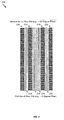
- FIG. 2 shows a macroscopic view of the pre-strained test coupon 200.
- the first loading operation 102 results in stress induced cracks between fibers of each of the second ply layers, as illustrated by the irregularity of the individual second ply layers and voids/spacing between the second ply layers.
- the pre-strained test coupon 200 includes first fibers that are oriented in a first direction and second fibers that are oriented in a second direction (that is different from the first direction).
- a ply having ply layers with fibers oriented in the first direction is also referred to herein as a Zero-Degree ply
- a ply having ply layers with fibers oriented in the second direction is also referred to herein as a Ninety-Degree ply.
- the (substantially) zero/ninety degree orientations refer to fiber orientations with respect to a tensile loading direction when performing loading operations.
- the pre-strained composite test coupon 200 illustrated in FIG. 2 includes a first set of plies 204 associated with the first ply layers and a second set of plies 206 associated with the second ply layers.
- the first set of plies 204 includes a first number of plies
- the second set of plies 206 includes a second number of plies.
- FIG. 2 illustrates that, in some cases, the first number of plies may be same as the second number of plies.
- the first number of plies may include at least two plies (e.g., four plies in FIG. 2 )
- the second number of plies may include at least two plies (e.g., four plies in FIG. 2 ).
- the pre-strained composite test coupon 200 includes eight symmetrically arranged plies.
- the arrangement of plies includes a first ply 208, a second ply 210, a third ply 212, a fourth ply 214, a fifth ply 216, a sixth ply 218, a seventh ply 220, and an eighth ply 222.
- the second ply 210 (of the first set of plies 204) is disposed adjacent to the first ply 208 (of the second set of plies 206).
- the third ply 212 (of the second set of plies 206) is disposed adjacent to the second ply 210.
- the fourth ply 214 (of the first set of plies 204) is disposed adjacent to the third ply 212.
- the fifth ply 216 (of the first set of plies 204) is disposed adjacent to the fourth ply 214.
- the sixth ply 218 (of the second set of plies 206) is disposed adjacent to the fifth ply 216.
- the seventh ply 220 (of the first set of plies 204) is disposed adjacent to the sixth ply 218.
- the eighth ply 222 (of the second set of plies 206) is disposed adjacent to the seventh ply 220.
- tensile loading on the test coupon 200 may be reduced (e.g., to substantially zero, as illustrated in the example graph of FIG. 4 ).
- the testing device 304 may increase tensile loading on the test coupon 200 to test coupon failure, as shown at 310.
- the testing device 304 may be configured to measure strain values of the test coupon 200 during tensile loading of the test coupon 200 to the failure load.
- the threshold load may be in a range of about 85 percent to about 99 percent of the failure load, such as in a range of about 85 percent to about 95 percent of the failure load, in a range of about 87 percent to about 93 percent of the failure load, or in a range of about 89 percent to about 91 percent of the failure load.
- the application(s) 634 may include instructions that are executable by the processor 620 to send a second set of instructions to the testing device 682 to perform a second loading operation on the (pre-stressed) test coupon.
- the second loading operation may include increasing tensile loading of the (pre-stressed) test coupon to the failure load.
- the application(s) 634 may include instructions executable by the processor 620 to receive, from the testing device 682, strain values of the test coupon during tensile loading of the test coupon to the failure load.
- the instructions may be further executable by the processor 620 to calculate one or more modulus values associated with the first ply layers based on the measured strain values.
- the modulus value(s) may be calculated based on nominal thickness values associated with the first ply layers of the test coupon.
Landscapes
- Physics & Mathematics (AREA)
- Health & Medical Sciences (AREA)
- Life Sciences & Earth Sciences (AREA)
- Chemical & Material Sciences (AREA)
- Analytical Chemistry (AREA)
- Biochemistry (AREA)
- General Health & Medical Sciences (AREA)
- General Physics & Mathematics (AREA)
- Immunology (AREA)
- Pathology (AREA)
- Investigating Strength Of Materials By Application Of Mechanical Stress (AREA)
Abstract
Description
- The present disclosure is generally related to pre-strained composite test coupons.
- Some test methods for determination of strength and modulus of a composite laminate material may undervalue a material capability of particular portions of the composite laminate material. Further, some test methods may not provide consistent results at various test conditions.
- In a particular embodiment, a composite test coupon is disclosed that includes a plurality of plies. The plurality of plies include first ply layers and second ply layers. The first ply layers have first fibers and a substantially uniform matrix material associated with the first fibers. The second ply layers have second fibers and a pre-stressed matrix material associated with the second fibers. The first fibers are oriented in a first direction, and the second fibers are oriented in a second direction that is different from the first direction. The pre-stressed matrix material includes stress induced cracks between the second fibers of each of the second ply layers.
- In another particular embodiment, a method includes inserting a test coupon of a composite material into a testing device and performing loading operations on the test coupon. The test coupon has a plurality of layers, and the testing device has a first element to secure the test coupon and a second element to secure the test coupon. The plurality of layers of the test coupon are arranged in a cross-ply layup that includes first ply layers and second ply layers. The first ply layers have first fibers and a first matrix material associated with the first fibers, with the first fibers oriented in a first direction. The second ply layers have second fibers and a second matrix material associated with the second fibers, with the second fibers oriented in a second direction that is different from the first direction. The method includes performing a first loading operation on the test coupon. The first loading operation includes applying a first tensile load oriented in the first direction, with the first tensile load corresponding to a threshold load that is less than a failure load. After performing the first loading operation, the method further includes performing a second loading operation on the test coupon. The second loading operation includes increasing tensile loading of the test coupon to the failure load.
- In another particular embodiment, a system includes a processor and a memory in communication with the processor. The memory includes instructions that are executable by the processor to perform various operations. The operations include communicating with a testing device that is configured to perform load testing operations on a test coupon of a composite material having a plurality of layers. The plurality of layers of the test coupon are arranged in a cross-ply layup including first ply layers and second ply layers. The first ply layers have first fibers and a first matrix material associated with the first fibers, with the first fibers oriented in a first direction. The second ply layers have second fibers and a second matrix material associated with the second fibers. The second fibers are oriented in a second direction that is different than the first direction. The operations also include sending a first set of instructions to the testing device to perform a first loading operation on the test coupon. The first loading operation includes applying a first tensile load oriented in the first direction, with the first tensile load corresponding to a threshold load that is less than a failure load. The operations further include sending a second set of instructions to the testing device to perform a second loading operation on the test coupon. The second loading operation includes increasing tensile loading of the test coupon to the failure load.
- The features, functions, and advantages that have been described can be achieved independently in various embodiments or may be combined in other embodiments, further details of which are disclosed with reference to the following description and drawings.
-
-
FIG. 1 is a diagram illustrating a test coupon of a composite material during a first loading operation to pre-strain the test coupon by applying a tensile load corresponding to a threshold load that is less than a failure load, according to one embodiment; -
FIG. 2 is a diagram illustrating a composite test coupon after the first loading operation (e.g., a ``pre-strained" composite test coupon), according to one embodiment; -
FIG. 3 is a diagram illustrating a second loading operation that includes increasing tensile loading of a pre-strained composite test coupon to a failure load, according to one embodiment; -
FIG. 4 is a diagram illustrating an example of deflection of a composite test coupon during the first loading operation and the second loading operation, according to one embodiment; -
FIG. 5 is a flow chart illustrating a particular embodiment of a method of performing a first loading operation to pre-strain a composite test coupon prior to performing a second loading operation that includes increasing tensile loading of the test coupon to a failure load; and -
FIG. 6 is an illustration of a block diagram of a computing environment including a general purpose computing device configured to support embodiments of computer-implemented methods and computer-executable program instructions (or code) according to the present disclosure. - The present disclosure describes a test coupon that includes a composite material (also referred to herein as a "composite test coupon") and methods of performing various loading operations on the test coupon. In the present disclosure, the test coupon includes a plurality of layers that are arranged in a cross-ply layup. The cross-ply layup includes first ply layers and second ply layers. The first ply layers have first fibers and a first matrix material associated with the first fibers. The second ply layers have second fibers and a second matrix material associated with the second fibers. The first fibers are oriented in a first direction, and the second fibers are oriented in a second direction that is different from the first direction. A ply layer with fibers oriented in the first direction is also referred to herein as a Zero-Degree ply layer, while a ply layer with fibers oriented in the second direction is also referred to herein as a Ninety-Degree ply layer. The (substantially) zero/ninety degree orientations refer to fiber orientations with respect to a tensile loading direction when performing loading operation(s) on the test coupon. Although zero/ninety degree angles are used to describe directional differences but with fibers of different layers, it will be appreciated that alternative angles between directions are also contemplated, such as 30 degree angles or 45 degree angles, among other alternatives.
- In the present disclosure, a test coupon may be "pre-strained" by performing a first loading operation on the test coupon. The first loading operation includes applying a first tensile load oriented in the first direction (corresponding to fiber orientation in the Zero-Degree ply layers), with the first tensile load corresponding to a threshold load that is less than a failure load. The application of the first tensile load to the second matrix material (associated with the Ninety-Degree ply layers) may result in a pre-stressed matrix material that includes stress induced cracks between fibers of each of the Ninety-Degree ply layers. After performing the first loading operation, a second loading operation may be performed in order to calculate strength/modulus value(s) for the Zero-Degree ply layers. Further, surface area of the test coupon that is associated with the Ninety-Degree ply layers may allow loading operations to be performed without applying adhesive tabs to the composite test coupon. As adhesives may degrade under some testing conditions (e.g., high temperature and/or high humidity conditions), the composite test coupon of the present disclosure may allow for "harsh environment" load testing operations to be performed.
- Unlike test methods for "unidirectional" test coupons that may under-value a material capability and may not offer consistent results at various test conditions, the test coupon(s) and test method(s) of the present disclosure may allow a test coupon to be used to determine both ultimate strength and (elastic tensile) modulus from zero to failure strain under a variety of test conditions. The test coupon(s) of the present disclosure may reduce a number of tests to be performed in order to characterize a composite material at ply level and may improve accuracy of calculated material strength values.
- Further, "unidirectional" coupons may also be susceptible to damage at the ends of the coupons from test machine grips. To prevent such grip damage, adhesives may be used to bond fiberglass tabs to the ends of the "unidirectional" test coupons. However, the use of such adhesives may not allow for accurate testing at elevated temperature with wet conditioned coupons, as the bond is likely to fail before the coupon ultimate strength is reached under such conditions. Additionally, the process of bonding is expensive and time-consuming, and tab quality is inconsistent (being heavily influenced by the skill of the person bonding the tabs).
- The cross-ply layup of the test coupon of the present disclosure may include outer plies (at substantially 90 degrees) that may protect load carrying inner plies (at substantially 0 degrees) from damage from the test machine grips. The outer plies (along with friction pads, in some cases) may allow the composite test coupons of the present disclosure to be tested without the use of adhesive tabs, allowing for more accurate testing of specimens under elevated temperature/humidity conditions. The outer plies (at substantially 90 degrees) may also transversely support the load-carrying inner plies (at substantially 0 degrees) and suppress transverse splitting in the test coupon before a fiber direction strength failure. An elastic modulus calculation may be updated to remove a contribution of the outer plies.
- As an illustrative example of a test method, the test coupon of the present disclosure may be loaded to a threshold load (e.g., about 90 percent of an expected ultimate failure load), allowing a matrix material in the outer plies to crack and eliminating load transfer between fibers in the outer plies. The test coupon may then be unloaded (e.g., to approximately zero pounds), and the test coupon may then be reloaded at an original load rate until ultimate failure is achieved. Coupon strain data may be recorded during the testing process. The final failure stress and elastic modulus may be attributed to the inner plies and may be calculated accordingly (e.g., based on nominal thickness of ply area associated with the Zero-Degree plies). Elastic modulus equations may be applied over the range of sampled points, and values may be averaged between replicates at each strain interval. A curve may be fit to the averaged data in order to provide a second order polynomial equation. Thus, rather than determining a tensile elastic modulus at a single strain, the second order polynomial equation describes a nonlinear relationship between elastic modulus and strain for a range of strain values.
- Referring to
FIG. 1 , a diagram 100 illustrates a particular embodiment of a loading operation to pre-strain a test coupon that includes a composite material. While not shown inFIG. 1 , a testing device (e.g., an extensometer, as shown inFIG. 3 ) may be used to perform various loading operations on test coupon(s). -
FIG. 1 illustrates a test coupon of a composite material at various stages during application of various loads to the test coupon as part of afirst loading operation 102. The test coupon includes a plurality of layers arranged in a cross-ply layup. The cross-ply layup includes first ply layers having first fibers and a first matrix material associated with the first fibers. The cross-ply layup also includes second ply layers having second fibers and a second matrix material associated with the second fibers. The first fibers are oriented in a first direction (e.g., along a length of a page when the test coupon is oriented as shown inFIG. 1 ), and the second fibers are oriented in a second direction that is different than the first direction (e.g., into and/or out of the page when the test coupon is oriented as shown inFIG. 1 ). - The
first loading operation 102 may be used to form a "pre-strained" composite test coupon for subsequent testing, as described further herein with respect toFIGS. 2 and3 . In the particular embodiment illustrated inFIG. 1 , a result of application of a first load (e.g., about 25 percent of a failure load) to the test coupon is illustrated at 104. A result of application of a second load (e.g., about 50 percent of the failure load) to the test coupon is illustrated at 106. A result of application of a third load (e.g., a threshold load that is less than the failure load, such as about 90 percent of the failure load) to the test coupon is illustrated at 108. While not shown inFIG. 1 , after loading the test coupon to the threshold load, the tensile load on the test coupon may be reduced (e.g., to substantially zero), as shown in the example graph ofFIG. 4 . The resulting test coupon is also referred to herein as a "pre-strained" test coupon, as illustrated and further described herein with respect toFIG. 2 . - In some cases, a substantially similar "sacrificial" test coupon (e.g., having the same cross-ply layup) may be used to determine an expected failure load. The threshold load may be determined based on the failure load that is measured for the sacrificial test coupon. For example, the threshold load may be in a range of about 85 percent to about 99 percent of the failure load, such as in a range of about 85 percent to about 95 percent of the failure load, in a range of about 87 percent to about 93 percent of the failure load, or in a range of about 89 percent to about 91 percent of the failure load. In a particular embodiment, the threshold load may be about 90 percent of the failure load. In some cases, acoustic testing of a pre-strained test coupon may be used to determine whether a particular threshold load value is indicative of substantial cracks being formed in the matrix material of the second ply layers.
- Cracks in the matrix material of the second ply layers may result in a significant reduction in a contribution of the second ply layers to an overall tensile strength of a test coupon. Substantial removal of the contribution of the second ply layers to the overall tensile strength may allow for a more accurate determination of a tensile strength associated with the first ply layers. During subsequent loading operations on a pre-strained test coupon, the second ply layers may provide additional surface area for securing the pre-strained test coupon to a testing device in order to avoid the use of adhesive tabs for securing the test coupon. As adhesive tabs may be subject to degradation under certain conditions (e.g., high temperature and/or high humidity), the ability to secure a test coupon to a testing device without adhesive tabs may allow for load testing operations to be performed under a wide range of conditions (e.g., harsh environment testing). Accordingly, the
first loading operation 102 may be performed above a temperature threshold (e.g., associated with adhesive tab de-bonding), above a humidity threshold (e.g., a "wet" environment associated with adhesive tab de-bonding), or a combination thereof. - Thus,
FIG. 1 illustrates an example of a first loading operation performed on a test coupon of a composite material that includes a plurality of plies arranged in a cross-ply layup. The application of a threshold load that is less than an expected failure load of a test coupon results in the formation of a pre-strained composite test coupon for subsequent load testing operations, as further described herein. - Referring to
FIG. 2 , an example of a pre-strained composite test coupon is illustrated and is generally designated 200. In a particular embodiment, the pre-strainedcomposite test coupon 200 ofFIG. 2 may correspond to the test coupon ofFIG. 1 after application of the threshold load and subsequent reduction of the tensile load (e.g., to substantially zero). - In
FIG. 2 , the pre-strainedcomposite test coupon 200 includes a plurality of layers that are arranged in a cross-ply layup that includes first ply layers and second ply layers. The first ply layers and the second ply layers have fibers and matrix material(s) associated with the fibers. In some cases, the first ply layers and the second ply layers have substantially similar material compositions. To illustrate, the first ply layers and the second ply layers may be the same material, and the first/second ply layers are "turned" 90 degrees with respect to one another. Thus, for ease of illustration purposes only,FIG. 2 shows a macroscopic view of thepre-strained test coupon 200. As described further herein with respect toFIG. 1 , thefirst loading operation 102 results in stress induced cracks between fibers of each of the second ply layers, as illustrated by the irregularity of the individual second ply layers and voids/spacing between the second ply layers. - The
pre-strained test coupon 200 includes first fibers that are oriented in a first direction and second fibers that are oriented in a second direction (that is different from the first direction). A ply having ply layers with fibers oriented in the first direction is also referred to herein as a Zero-Degree ply, while a ply having ply layers with fibers oriented in the second direction is also referred to herein as a Ninety-Degree ply. The (substantially) zero/ninety degree orientations refer to fiber orientations with respect to a tensile loading direction when performing loading operations. - The pre-strained
composite test coupon 200 illustrated inFIG. 2 includes a first set ofplies 204 associated with the first ply layers and a second set ofplies 206 associated with the second ply layers. The first set ofplies 204 includes a first number of plies, and the second set ofplies 206 includes a second number of plies.FIG. 2 illustrates that, in some cases, the first number of plies may be same as the second number of plies. In a particular embodiment, the first number of plies may include at least two plies (e.g., four plies inFIG. 2 ), and the second number of plies may include at least two plies (e.g., four plies inFIG. 2 ). - In the particular embodiment illustrated in
FIG. 2 , the pre-strainedcomposite test coupon 200 includes eight symmetrically arranged plies. In the example ofFIG. 2 , the arrangement of plies includes afirst ply 208, asecond ply 210, athird ply 212, afourth ply 214, afifth ply 216, asixth ply 218, aseventh ply 220, and aneighth ply 222. The second ply 210 (of the first set of plies 204) is disposed adjacent to the first ply 208 (of the second set of plies 206). The third ply 212 (of the second set of plies 206) is disposed adjacent to thesecond ply 210. The fourth ply 214 (of the first set of plies 204) is disposed adjacent to thethird ply 212. The fifth ply 216 (of the first set of plies 204) is disposed adjacent to thefourth ply 214. The sixth ply 218 (of the second set of plies 206) is disposed adjacent to thefifth ply 216. The seventh ply 220 (of the first set of plies 204) is disposed adjacent to thesixth ply 218. The eighth ply 222 (of the second set of plies 206) is disposed adjacent to theseventh ply 220. - As an alternative example of a symmetrical arrangement of plies, a pre-stressed test coupon may include two plies associated with the first set of
plies 204 and two plies associated with the second set ofplies 206. To illustrate, the first set ofplies 204 may include thefourth ply 216 and the fifth ply 218 (without thesecond ply 210 and theseventh ply 220 shown inFIG. 2 ), and the second set ofplies 206 may include thethird ply 212 and the sixth ply 218 (without thefirst ply 208 and theeighth ply 222 shown inFIG. 2 ). It will be appreciated that a pre-stressed test coupon may include an alternative number and/or arrangement of plies. - Thus,
FIG. 2 illustrates an example of a "pre-strained" composite test coupon that includes a plurality of plies arranged in a cross-ply layup. As described further herein, the first loading operation to pre-stress the second matrix material (associated with the Ninety-Degree ply layers) results in the pre-strained composite test coupon with stress induced cracks in the second matrix material. As described further herein with respect toFIG. 3 , a second loading operation that is performed on the pre-strained composite test coupon may provide a more accurate estimate of strength/modulus value(s) for the Zero-Degree ply layers. -
FIG. 3 is a diagram 300 that illustrates an example of asecond loading operation 302 that includes increasing tensile loading of a test coupon (e.g., the pre-strainedcomposite test coupon 200 ofFIG. 2 ) to a failure load.FIG. 3 illustrates that surface area of the test coupon that is associated with the Ninety-Degree ply layers may allow thesecond loading operation 302 to be performed without applying adhesive tabs to the test coupon. As adhesives may degrade under some testing conditions (e.g., high temperature and/or high humidity conditions), thesecond loading operation 302 may correspond to a "harsh environment" load testing operation (in some cases), such as above a temperature threshold (e.g., associated with adhesive tab de-bonding), above a humidity threshold (e.g., a "wet" environment associated with adhesive tab de-bonding), or a combination thereof. -
FIG. 3 illustrates that thetest coupon 200 may be inserted into a testing device 304 (e.g., an extensometer). Thetesting device 304 includes afirst element 306 to secure the test coupon 200 (identified as "Coupon Securing Element(1)" inFIG. 3 ) and a second element to secure the test coupon 200 (identified as "Coupon Securing Element(2)" inFIG. 3 ). As further illustrated in the example ofFIG. 2 , thetest coupon 200 may not include adhesive tabs for securing thetest coupon 200 to thefirst element 306 and thesecond element 308 of thetesting device 304. As adhesive tabs may degrade under some testing conditions (e.g., high temperature/humidity, etc.), securing thetest coupon 200 within thetesting device 304 without the use of adhesive tabs may allow thesecond loading operation 302 to be performed above a temperature threshold, above a humidity threshold, or a combination thereof. In some cases, thefirst element 306 may include a first friction pad to secure a first end of thetest coupon 200, and thesecond element 308 may include a second friction pad to secure a second end of thetest coupon 200. - After performing the first loading operation 102 (as illustrated and further described herein with respect to
FIG. 1 ), tensile loading on thetest coupon 200 may be reduced (e.g., to substantially zero, as illustrated in the example graph ofFIG. 4 ). Thetesting device 304 may increase tensile loading on thetest coupon 200 to test coupon failure, as shown at 310. Thetesting device 304 may be configured to measure strain values of thetest coupon 200 during tensile loading of thetest coupon 200 to the failure load. - In some cases, the testing device 304 (or another computing device) may be configured to calculate one or more modulus values associated with the first ply layers based on the measured strain values. In a particular embodiment, the one or more modulus values may be determined based on nominal thickness values associated with the first ply layers based on the measured strain values. As an illustrative example, referring to
FIG. 2 , a total nominal thickness value for use in calculating modulus value(s) may be determined based on individual nominal thickness values for each ply layer of the first set ofplies 204. To illustrate, the total nominal thickness value may be determined based on nominal thickness values for each ply layer associated with the second ply 210 (of the first set of plies 204), nominal thickness values for each ply layer associated with the fourth ply 214 (of the first set of plies 204), nominal thickness values for each ply layer associated with the fifth ply 216 (of the first set of plies 204), and nominal thickness values for each ply layer associated with the seventh ply 220 (of the first set of plies 204). - While not shown in the example of
FIG. 3 , in some cases, thetesting device 304 may determine the failure load using a sacrificial test coupon. The sacrificial test coupon may have a substantially similar test coupon design (e.g., an "unstressed" test coupon prior to performing thefirst loading operation 102 illustrated inFIG. 1 ). The threshold load that is applied during the first loading operation 102 (ofFIG. 1 ) may be determined based on the measured failure load of the sacrificial test coupon. In a particular embodiment, the threshold load may be in a range of about 85 percent to about 99 percent of the failure load, such as in a range of about 85 percent to about 95 percent of the failure load, in a range of about 87 percent to about 93 percent of the failure load, or in a range of about 89 percent to about 91 percent of the failure load. - Thus,
FIG. 3 illustrates an example of a second loading operation that includes increasing tensile loading of a pre-strained composite test coupon to a failure load. As described further herein, strength/modulus values associated with the second loading operation may provide a more accurate estimate of strength/modulus value(s) for the Zero-Degree ply layers. Further, in some cases, the second loading operation may be performed under "harsh environment" conditions (e.g., high temperature and/or high humidity conditions) that may correspond to conditions that may be expected for materials that include the Zero-Degree ply layers. -
FIG. 4 is a diagram 400 depicting an illustrative, non-limiting example of measured values (e.g., deflection of a composite test coupon) during the first loading operation and the second loading operation, as described further herein with respect toFIG. 1 andFIG. 3 . InFIG. 4 , the first loading operation (and associated unloading) is illustrated as a solid line, while the second loading operation is illustrated as a dashed line. - In the particular embodiment illustrated in
FIG. 4 , the solid line illustrates that performing the first loading operation on the test coupon (e.g., as illustrated inFIG. 1 ) includes increasing tensile loading to athreshold load 402 that is less than afailure load 404. While not shown inFIG. 4 , in some cases, thefailure load 404 may be determined for a sacrificial test coupon in order to calculate thethreshold load 402 to be applied to the test coupon during the first loading operation. -
FIG. 4 illustrates a particular example in which thethreshold load 402 is about 12,000 pounds, and thefailure load 404 is about 14,000 pounds. In this case, thethreshold load 402 represents about 86 percent of thefailure load 404. However, it will be appreciated that thethreshold load 402 may include an alternative load, such as a load in a range of in a range of about 85 percent to about 99 percent of thefailure load 404, in a range of about 85 percent to about 95 percent of thefailure load 404, in a range of about 87 percent to about 93 percent of thefailure load 404, or in a range of about 89 percent to about 91 percent of thefailure load 404. -
FIG. 4 further illustrates that, after performing the first loading operation, the test coupon may be "unloaded" prior to performing the second loading operation. In the particular embodiment illustrated inFIG. 4 , the load on the test coupon is reduced to a tensile load of substantially zero. In some cases, the first loading operation and subsequent unloading operation may result in formation of thepre-strained test coupon 200 ofFIG. 2 . As illustrated in the example ofFIG. 3 , the second loading operation (e.g., to thefailure load 404 ofFIG. 4 ) may result in failure of the pre-strained test coupon (as shown at 310). As further described herein with respect toFIG. 2 , values that are measured during the second loading operation may be used to calculate strength/modulus values for the Zero-Degree ply layers. For example, strength/modulus values for the Zero-Degree ply layers may be calculated based on nominal thickness values for the Zero-Degree ply layers (with the contribution of Ninety-Degree ply layers ignored/removed). - Thus,
FIG. 4 illustrates an example of a first loading operation performed on a test coupon that includes a composite material in order to form stress induced cracks in a matrix material associated with the Ninety-Degree ply layers. After performing the first loading operation (and associated unloading operation) to form a pre-strained test coupon, a second loading operation may be performed on the pre-strained test coupon. Values that are measured for the pre-strained test coupon during the second loading operation may be used to calculate strength/modulus values for the Zero-Degree ply layers. - Referring to
FIG. 5 , a particular embodiment of amethod 500 of performing a first loading operation on a test coupon that includes a composite material in order to form a pre-strained composite test coupon prior to performing a second loading operation that includes increasing tensile loading on the pre-strained composite test coupon to a failure load. While not shown inFIG. 5 , in some embodiments, a substantially similar sacrificial test coupon may be used to measure a failure load, and the measured failure load may be used to calculate the threshold load to be applied during a first loading operation for another test coupon. - The
method 500 includes inserting a test coupon of a composite material having a plurality of layers into a testing device to secure the test coupon, at 502. The layers of the test coupon are arranged in a cross-ply layup that includes first ply layers and second ply layers. The first ply layers have first fibers oriented in a first direction and a first matrix material. The second ply layers have second fibers oriented in a second direction (that is different from the first direction) and a second matrix material. For example, referring toFIG. 3 , thetesting device 304 may be used to secure an "unstrained" test coupon that includes a composite material. WhileFIG. 3 illustrates the pre-strainedcomposite test coupon 200 being secured in thetesting device 304, it will be appreciated that thetesting device 304 ofFIG. 3 may be used to secure/load test an unstrained test coupon in order to form thepre-strained test coupon 200 prior to increasing tensile load on thepre-strained test coupon 200 in order to induce test coupon failure (as shown at 310). - The
method 500 includes performing a first loading operation on the test coupon, at 504. The first loading operation includes applying a first tensile load (e.g., a threshold load that is less than a failure load) that is oriented in the first direction (e.g., substantially corresponding to an orientation of the Zero-Degree ply layers). For example, referring toFIG. 1 , thefirst loading operation 102 may be performed on an "unstrained" test coupon that includes a composite material. As described further herein, thefirst loading operation 102 illustrated inFIG. 1 may result in formation of the pre-strainedcomposite test coupon 200 ofFIG. 2 . - After performing the first loading operation, the
method 500 includes performing a second loading operation on the test coupon, at 506. Themethod 500 may further comprise the step of removing any application of a tensile load to the test coupon or specimen after performing the first loading operation and before performing the second loading operation. The second loading operation includes increasing tensile loading of the test coupon to the failure load. For example, referring toFIG. 3 , thesecond loading operation 302 may performed on thepre-strained test coupon 200. As shown in the example ofFIG. 3 , thesecond loading operation 302 may result in test coupon failure, as shown at 310. While not shown in the example ofFIG. 5 , it will be appreciated that values may be measured while performing the second loading operation on the pre-strained test coupon. The measured values may be used to calculate strength/modulus values for the Zero-Degree ply layers (e.g., based on nominal thickness values). - Thus,
FIG. 5 illustrates a particular example of a method of performing a first loading operation on a test coupon that includes a composite material, resulting in stress induced cracks in the Ninety-Degree ply layers. After forming the stress induced cracks, a second loading operation is performed in order to measure values for the pre-strained test coupon. The values that are measured for the pre-strained test coupon may be used to calculate strength/modulus values for the Zero-Degree ply layers. WhileFIG. 5 illustrates that the first loading operation and the second loading operation are applied to a test coupon, it will be appreciated that one entity may perform the first loading operation (e.g., to form a pre-strained test coupon), while another entity may perform the second loading operation (e.g., applying a tensile load to the pre-strained test coupon to induce failure). -
FIG. 6 is an illustration of a block diagram of acomputing environment 600 including a generalpurpose computing device 610 configured to support embodiments of computer-implemented methods and computer-executable program instructions (or code) according to the present disclosure. For example, thecomputing device 610, or portions thereof, may execute instructions to communicate with atesting device 682 to perform loading operation(s) on a test coupon of a composite material. For example, thetesting device 682 ofFIG. 6 may correspond to thetesting device 304 ofFIG. 3 . Thecomputing device 610, or portions thereof, may further execute instructions according to any of the methods described herein. For example, thecomputing device 610 may execute instructions according to themethod 500 described with respect toFIG. 5 . - The
computing device 610 may include aprocessor 620. Theprocessor 620 may communicate with thesystem memory 630, one ormore storage devices 640, one or more input/output interfaces 650, one ormore communications interfaces 660, or a combination thereof. Thesystem memory 630 may include volatile memory devices (e.g., random access memory (RAM) devices), nonvolatile memory devices (e.g., read-only memory (ROM) devices, programmable read-only memory, and flash memory), or both. Thesystem memory 630 may include anoperating system 632, which may include a basic/input output system for booting thecomputing device 610 as well as a full operating system to enable thecomputing device 610 to interact with users, other programs, and other devices. Thesystem memory 630 may include one ormore applications 634 which may be executable by theprocessor 620. For example, the one ormore applications 634 may include instructions executable by theprocessor 620 to perform various operations (e.g., loading operations). Further, thesystem memory 630 may includeprogram data 636 usable for controlling thetesting device 682 to perform the loading operations described herein. - As an example, the application(s) 634 may include instructions executable by the
processor 620 to communicate with thetesting device 682 that is configured to perform load testing operations on a test coupon of a composite material having a plurality of layers, where the plurality of layers of the test coupon are arranged in a cross-ply layup. As illustrated and further described herein with respect toFIG. 1 , prior to performing thefirst loading operation 102, an "unstressed" test coupon may include first ply layers and second ply layers. The first ply layers have first fibers and a first matrix material associated with the first fibers, and the second ply layers have second fibers and a second matrix material associated with the second fibers. The second fibers are oriented in a second direction that is different than the first direction. - As another example, the application(s) 634 may include instructions executable by the
processor 620 to send a first set of instructions to thetesting device 682 to perform a first loading operation on a test coupon. As illustrated and further described herein with respect toFIG. 1 , the first loading operation may include applying a tensile load oriented in a first direction (of fibers of the first ply layers), with the tensile load corresponding to a threshold load that is less than a failure load. - As a further example, the application(s) 634 may include instructions that are executable by the
processor 620 to send a second set of instructions to thetesting device 682 to perform a second loading operation on the (pre-stressed) test coupon. As illustrated and further described herein with respect toFIG. 3 , the second loading operation may include increasing tensile loading of the (pre-stressed) test coupon to the failure load. - As another example, the application(s) 634 may include instructions executable by the
processor 620 to receive, from thetesting device 682, strain values of the test coupon during tensile loading of the test coupon to the failure load. The instructions may be further executable by theprocessor 620 to calculate one or more modulus values associated with the first ply layers based on the measured strain values. As described further herein with respect toFIG. 3 , the modulus value(s) may be calculated based on nominal thickness values associated with the first ply layers of the test coupon. - As another example, the application(s) 634 may include instructions executable by the
processor 620 to (prior to performing the first loading operation) send a third set of instructions to thetesting device 682 to perform a failure load testing operation on a sacrificial test coupon that is substantially similar to the test coupon. The instructions may be further executable by theprocessor 620 to calculate the threshold load based on information received from thetesting device 682 that is associated with the failure load testing operation on the sacrificial test coupon. - The
processor 620 may also communicate with one ormore storage devices 640. For example, the one ormore storage devices 640 may include nonvolatile storage devices, such as magnetic disks, optical disks, or flash memory devices. Thestorage devices 640 may include both removable and non-removable memory devices. Thestorage devices 640 may be configured to store an operating system, images of operating systems, applications, and program data. Further, thestorage device 640 may be configured to store test values measured by thetesting device 682 and/or values that are calculated based on the measured test values (e.g., strength/modulus values for Zero-Degree ply layers). In a particular embodiment, thememory 630, thestorage devices 640, or both, include tangible computer-readable media. - The
processor 620 may also communicate with one or more input/output interfaces 650 that enable thecomputing device 610 to communicate with one or more input/output devices 670 to facilitate user interaction. As an example, thecomputing device 610 may communicate with a display device to display test values that are measured by thetesting device 682 and/or values that are calculated based on the measured test values (e.g., strength/modulus values for the Zero-Degree ply layers), among other alternatives. Theprocessor 620 may detect interaction events based on user input received via the input/output interfaces 650. Additionally, theprocessor 620 may send a display to a display device via the input/output interfaces 650. Theprocessor 620 may communicate with devices orcontrollers 680 via the one or more communications interfaces 660. For example, the devices orcontrollers 680 may correspond to thetesting device 304 ofFIG. 3 . - Embodiments described above are illustrative and do not limit the disclosure. It is to be understood that numerous modifications and variations are possible in accordance with the principles of the present disclosure.
- The illustrations of the embodiments described herein are intended to provide a general understanding of the structure of the various embodiments. The illustrations are not intended to serve as a complete description of all of the elements and features of apparatus and systems that utilize the structures or methods described herein. Many other embodiments may be apparent to those of skill in the art upon reviewing the disclosure. Other embodiments may be utilized and derived from the disclosure, such that structural and logical substitutions and changes may be made without departing from the scope of the disclosure. For example, method steps may be performed in a different order than is shown in the figures or one or more method steps may be omitted. Accordingly, the disclosure and the figures are to be regarded as illustrative rather than restrictive.
- Moreover, although specific embodiments have been illustrated and described herein, it is to be appreciated that any subsequent arrangement designed to achieve the same or similar results may be substituted for the specific embodiments shown. This disclosure is intended to cover any and all subsequent adaptations or variations of various embodiments. Combinations of the above embodiments, and other embodiments not specifically described herein, will be apparent to those of skill in the art upon reviewing the description.
- Further, the disclosure comprises embodiments according to the following clauses:
-
Clause 1. A composite test coupon comprising:- a plurality of plies including:
- first ply layers having first fibers and a substantially uniform matrix material associated with the first fibers, the first fibers oriented in a first direction; and
- second ply layers having second fibers and a pre-stressed matrix material associated with the second fibers, the second fibers oriented in a second direction that is different from the first direction, wherein the pre-stressed matrix material includes stress induced cracks between the second fibers of each of the second ply layers.
- a plurality of plies including:
-
Clause 2. The composite test coupon ofClause 1, wherein the plurality of plies includes:- a first set of plies associated with the first ply layers, the first set of plies including a first number of plies; and
- a second set of plies associated with the second ply layers, the second set of plies including a second number of plies.
- Clause 3. The composite test coupon of
Clause 2, wherein the first number of plies is the same as the second number of plies. - Clause 4. The composite test coupon of
Clause 2, wherein the first number of plies includes at least two plies, and wherein the second number of plies includes at least two plies. - Clause 5. The composite test coupon of Clause 4, wherein the first number of plies includes four plies, and wherein the second number of plies includes four plies.
- Clause 6. The composite test coupon of
Clause 2, wherein an arrangement of the plurality of plies includes:- a first ply of the second set of plies;
- a second ply of the first set of plies, the second ply disposed adjacent to the first ply;
- a third ply of the first set of plies, the third ply disposed adjacent to the second ply; and
- a fourth ply of the second set of plies, the fourth ply disposed adjacent to the third ply.
- Clause 7. The composite test coupon of
Clause 2, wherein an arrangement of the plurality of plies includes:- a first ply of the second set of plies;
- a second ply of the first set of plies, the second ply disposed adjacent to the first ply;
- a third ply of the second set of plies, the third ply disposed adjacent to the second ply;
- a fourth ply of the first set of plies, the fourth ply disposed adjacent to the third ply;
- a fifth ply of the first set of plies, the fifth ply disposed adjacent to the fourth ply;
- a sixth ply of the second set of plies, the sixth ply disposed adjacent to the fifth ply;
- a seventh ply of the first set of plies, the seventh ply disposed adjacent to the sixth ply; and
- an eighth ply of the second set of plies, the eighth ply disposed adjacent to the seventh ply.
- Clause 8. The composite test coupon of any of
Clauses 1 to 7, wherein the first ply layers and the second ply layers have substantially similar material compositions. - Clause 9. A method comprising:
- inserting a test coupon of a composite material having a plurality of layers into a testing device that has a first element to secure the test coupon and a second element to secure the test coupon, wherein the plurality of layers of the test coupon are arranged in a cross-ply layup including:
- first ply layers having first fibers and a first matrix material associated with the first fibers, the first fibers oriented in a first direction; and
- second ply layers having second fibers and a second matrix material associated with the second fibers, the second fibers oriented in a second direction that is different than the first direction;
- performing a first loading operation on the test coupon, wherein the first loading operation includes applying a first tensile load oriented in the first direction, the first tensile load corresponding to a threshold load that is less than a failure load; and
- after performing the first loading operation, performing a second loading operation on the test coupon, wherein the second loading operation includes increasing tensile loading of the test coupon to the failure load.
- inserting a test coupon of a composite material having a plurality of layers into a testing device that has a first element to secure the test coupon and a second element to secure the test coupon, wherein the plurality of layers of the test coupon are arranged in a cross-ply layup including:
- Clause 10. The method of Clause 9, further comprising measuring strain values of the test coupon during tensile loading of the test coupon to the failure load.
- Clause 11. The method of Clause 10, further comprising calculating one or more modulus values associated with the first ply layers based on the measured strain values.
- Clause 12. The method of any of Clauses 9 to 11, further comprising the step of securing the test coupon to the first element (306) and second element (308) of the testing device (304), wherein the test coupon does not include adhesive tabs for securing the test coupon to the first element and the second element of the testing device.
- Clause 13. The method of any of Clauses 9 to 12, wherein the first loading operation and the second loading operation are performed above a temperature threshold, above a humidity threshold, or a combination thereof.
- Clause 14. The method of any of Clauses 9 to 13, further comprising, prior to performing the first loading operation, using the testing device to determine the failure load using a sacrificial test coupon that is substantially similar to the test coupon.
- Clause 15. The method of any of Clauses 9 to 14, wherein the step of applying the first tensile load corresponds to applying a threshold load that is in a range of about 85 percent to about 99 percent of the failure load.
- Clause 16. The method of any of Clauses 9 to 15, wherein the first element of the testing device includes a first friction pad to secure a first end of the test coupon, and wherein the second element of the testing device includes a second friction pad to secure a second end of the test coupon.
- Clause 17. A system comprising:
- a processor;
- a memory in communication with the processor, the memory including instructions executable by the processor to perform operations including:
- communicating with a testing device that is configured to perform load testing operations on a test coupon of a composite material having a plurality of layers, wherein the plurality of layers of the test coupon are arranged in a cross-ply layup including:
- first ply layers having first fibers and a first matrix material associated with the first fibers, the first fibers oriented in a first direction; and
- second ply layers having second fibers and a second matrix material associated with the second fibers, the second fibers oriented in a second direction that is different than the first direction;
- sending a first set of instructions to the testing device to perform a first loading operation on the test coupon, wherein the first loading operation includes applying a first tensile load oriented in the first direction, the first tensile load corresponding to a threshold load that is less than a failure load; and
- sending a second set of instructions to the testing device to perform a second loading operation on the test coupon, wherein the second loading operation includes increasing tensile loading of the test coupon to the failure load.
- communicating with a testing device that is configured to perform load testing operations on a test coupon of a composite material having a plurality of layers, wherein the plurality of layers of the test coupon are arranged in a cross-ply layup including:
- Clause 18. The system of Clause 17, wherein the operations further include:
- receiving, from the testing device, strain values of the test coupon during tensile loading of the test coupon to the failure load; and
- calculating one or more modulus values associated with the first ply layers based on the measured strain values.
- Clause 19. The system of Clause 18, wherein the one or more modulus values are determined based on nominal thickness values associated with the first ply layers of the plurality of layers of the test coupon.
- Clause 20. The system of Clause 17, wherein the operations further include:
- prior to performing the first loading operation, sending a third set of instructions to the testing device to perform a failure load testing operation on a sacrificial test coupon that is substantially similar to the test coupon; and
- calculating the threshold load based on information received from the testing device that is associated with the failure load testing operation on the sacrificial test coupon.
- The Abstract of the Disclosure is submitted with the understanding that it will not be used to interpret or limit the scope or meaning of the claims. In addition, in the foregoing Detailed Description, various features may be grouped together or described in a single embodiment for the purpose of streamlining the disclosure. This disclosure is not to be interpreted as reflecting an intention that the claimed embodiments require more features than are expressly recited in each claim. Rather, as the following claims reflect, the claimed subject matter may be directed to less than all of the features of any of the disclosed embodiments.
Claims (15)
- A composite test coupon (200) comprising:a plurality of plies (204, 206) including:first ply layers (208) having first fibers and a substantially uniform matrix material associated with the first fibers, the first fibers oriented in a first direction; andsecond ply layers (210) having second fibers and a pre-stressed matrix material associated with the second fibers, the second fibers oriented in a second direction that is different from the first direction, wherein the pre-stressed matrix material includes stress induced cracks between the second fibers of each of the second ply layers (210).
- The composite test coupon (200) of claim 1, wherein the plurality of plies (204, 206) includes:a first set of plies (204) associated with the first ply layers (208), the first set of plies (204) including a first number of plies; anda second set of plies (206) associated with the second ply layers (210), the second set of plies (206) including a second number of plies.
- The composite test coupon (200) of claim 2, wherein the first number of plies (204) is the same as the second number of plies.
- The composite test coupon (200) of claim 2, wherein the first number of plies includes at least two plies, and wherein the second number of plies includes at least two plies.
- The composite test coupon (200) of claim 4, wherein the first number of plies includes four plies, and wherein the second number of plies includes four plies.
- The composite test (200) coupon of claim 2, wherein an arrangement of the plurality of plies includes:a first ply (208) of the second set of plies (206);a second ply (210) of the first set of plies (204), the second ply (210) disposed adjacent to the first ply (208);a third ply (212) of the first set of plies, the third ply (212) disposed adjacent to the second ply (210); anda fourth ply (214) of the second set of plies (206), the fourth ply (214) disposed adjacent to the third ply (212).
- The composite test coupon (200) of claim 2, wherein an arrangement of the plurality of plies includes:a first ply (208) of the second set of plies (206);a second ply (210) of the first set of plies (204), the second ply (210) disposed adjacent to the first ply (208);a third ply (212) of the second set of plies (206), the third ply (212) disposed adjacent to the second ply (210);a fourth ply (214) of the first set of plies (204), the fourth ply (214) disposed adjacent to the third ply (212);a fifth ply (216) of the first set of plies (204), the fifth ply (216) disposed adjacent to the fourth ply (214);a sixth ply (218) of the second set of plies (206), the sixth ply (218) disposed adjacent to the fifth ply (216);a seventh ply (220) of the first set of plies (204), the seventh ply (220) disposed adjacent to the sixth ply (218); andan eighth ply (222) of the second set of plies (206), the eighth ply (222) disposed adjacent to the seventh ply (220).
- The composite test coupon (200) of any of claims 1 to 7, wherein the first ply layers (208) and the second ply layers (210) have substantially similar material compositions.
- A method (500) comprising:inserting a test coupon of a composite material (200) having a plurality of layers into a testing device (304) that has a first element (306) to secure the test coupon and a second element (308) to secure the test coupon, wherein the plurality of layers of the test coupon are arranged in a cross-ply layup including:first ply layers (208) having first fibers and a first matrix material associated with the first fibers, the first fibers oriented in a first direction; andsecond ply layers (210) having second fibers and a second matrix material associated with the second fibers, the second fibers oriented in a second direction that is different than the first direction;performing a first loading operation (102) on the test coupon (104), wherein the first loading operation (102) includes applying a first tensile load oriented in the first direction, the first tensile load corresponding to a threshold load (402) that is less than a failure load (404); andafter performing the first loading operation (102), performing a second loading operation (302) on the test coupon (106), wherein the second loading operation (302) includes increasing tensile loading of the test coupon to the failure load (108).
- The method (500) of claim 9, further comprising measuring strain values of the test coupon during tensile loading of the test coupon to the failure load (404).
- The method (500) of claim 10, further comprising calculating one or more modulus values associated with the first ply layers (208) based on the measured strain values.
- The method (500) of any of claims 9 to 11, further comprising the step of securing the test coupon to the first element (306) and second element (308) of the testing device (304), wherein the test coupon does not include adhesive tabs for securing the test coupon to the first element (306) and the second element (308) of the testing device (304).
- The method (500) of any of claims 9 to 12, wherein the first loading operation (102) and the second loading operation (302) are performed above a temperature threshold, above a humidity threshold, or a combination thereof.
- The method (500) of any of claims 9 to 13, further comprising, prior to performing the first loading operation (102), using the testing device (304) to determine the failure load (404) using a sacrificial test coupon that is substantially similar to the test coupon.
- The method (500) of any of claims 9 to 14, wherein the step of applying the first tensile load corresponds to applying a threshold load (402) that is in a range of about 85 percent to about 99 percent of the failure load (404).
Applications Claiming Priority (1)
| Application Number | Priority Date | Filing Date | Title |
|---|---|---|---|
| US14/727,236 US10190954B2 (en) | 2015-06-01 | 2015-06-01 | Pre-strained composite test coupons |
Publications (2)
| Publication Number | Publication Date |
|---|---|
| EP3101408A1 true EP3101408A1 (en) | 2016-12-07 |
| EP3101408B1 EP3101408B1 (en) | 2021-12-29 |
Family
ID=56096455
Family Applications (1)
| Application Number | Title | Priority Date | Filing Date |
|---|---|---|---|
| EP16169399.9A Active EP3101408B1 (en) | 2015-06-01 | 2016-05-12 | Pre-strained composite test coupons |
Country Status (2)
| Country | Link |
|---|---|
| US (1) | US10190954B2 (en) |
| EP (1) | EP3101408B1 (en) |
Cited By (1)
| Publication number | Priority date | Publication date | Assignee | Title |
|---|---|---|---|---|
| CN107907559A (en) * | 2017-11-13 | 2018-04-13 | 无锡威孚力达催化净化器有限责任公司 | A kind of test device of pad for auto-exhaust catalyst |
Families Citing this family (6)
| Publication number | Priority date | Publication date | Assignee | Title |
|---|---|---|---|---|
| US10746640B2 (en) * | 2017-03-21 | 2020-08-18 | Textron Innovations Inc. | Methods of making a tubular specimen with a predetermined wrinkle defect |
| US10744727B2 (en) | 2017-03-21 | 2020-08-18 | Textron Innovations Inc. | Methods of making a specimen with a predetermined wrinkle defect |
| WO2021127067A1 (en) | 2019-12-20 | 2021-06-24 | The Research Foundation For The State University Of New York | System and method for characterizing the equibiaxial compressive strength of 2d woven composites |
| CN111474041A (en) * | 2020-04-22 | 2020-07-31 | 重庆大学 | Method for Determining Elastic Properties of Prestressed Circular Membrane under Uniform Loads |
| US12240188B2 (en) | 2022-05-02 | 2025-03-04 | The Boeing Company | Apparatus and method for manufacturing thermoplastic wrinkle coupons |
| CN120213646B (en) * | 2025-05-27 | 2025-10-14 | 中材科技风电叶片股份有限公司 | Heterogeneous material fracture toughness testing method, double-cantilever beam sample and manufacturing method |
Citations (6)
| Publication number | Priority date | Publication date | Assignee | Title |
|---|---|---|---|---|
| US20060070452A1 (en) * | 2004-09-27 | 2006-04-06 | The Boeing Company | Visual documentation of micro-cracks during tensile coupon testing |
| US20100219294A1 (en) * | 2005-03-31 | 2010-09-02 | The Boeing Company | Composite beam chord between reinforcement plates |
| US8342017B1 (en) * | 2010-10-20 | 2013-01-01 | The Boeing Company | Methods for fabricating fiber-reinforced plastic test specimen assemblies having weak adhesive bonds |
| US20140234571A1 (en) * | 2013-02-18 | 2014-08-21 | The Boeing Company | Coupon Geometries That Induce Failure in Gauge Area of Composite Fatigue Test Coupons |
| US20140326074A1 (en) * | 2013-05-02 | 2014-11-06 | The Boeing Company | Methods and systems for rapidly testing adhesion |
| US20140333758A1 (en) * | 2013-05-10 | 2014-11-13 | The Boeing Company | Methods and systems for inspection of composite irregularities |
Family Cites Families (18)
| Publication number | Priority date | Publication date | Assignee | Title |
|---|---|---|---|---|
| JPS5226888A (en) * | 1975-08-26 | 1977-02-28 | Japan Synthetic Rubber Co Ltd | Automatic tension testing machine |
| FR2473567A1 (en) * | 1979-12-21 | 1981-07-17 | Brochier & Fils | COMPLEX WOVEN MATERIAL AND LAMINATE ARTICLES MADE THEREFROM |
| US5083465A (en) * | 1990-12-24 | 1992-01-28 | General Electric Company | Probe for an extensometer |
| US5305645A (en) * | 1992-05-04 | 1994-04-26 | The Center For Innovative Technology | Dynamic measurement of material strength and life under cyclic loading |
| US5866272A (en) * | 1996-01-11 | 1999-02-02 | The Boeing Company | Titanium-polymer hybrid laminates |
| US5844142A (en) * | 1997-04-30 | 1998-12-01 | Ethicon, Inc. | Pull test apparatus for permanently attached sutures |
| US6176142B1 (en) * | 1998-08-21 | 2001-01-23 | E. I. Du Pont De Nemours And Company | Composite coated jaw faces |
| US6370962B1 (en) * | 2000-06-14 | 2002-04-16 | Testing Machines, Inc. | Dynamic high speed tensile tester |
| DE10214756B4 (en) * | 2002-04-03 | 2011-06-16 | Mettler-Toledo Ag | Method and device for carrying out dynamic-mechanical analyzes |
| US7017422B2 (en) * | 2004-04-02 | 2006-03-28 | Luna Innovations Incorporated | Bond testing system, method, and apparatus |
| US8720825B2 (en) * | 2005-03-31 | 2014-05-13 | The Boeing Company | Composite stiffeners for aerospace vehicles |
| KR101212152B1 (en) | 2005-12-29 | 2012-12-13 | 엘지디스플레이 주식회사 | Organic Thin Film Transistor and Method for manufacturing the same |
| US8286498B1 (en) * | 2010-08-09 | 2012-10-16 | The United States Of America As Represented By The Secretary Of The Air Force | Method and device for tensile testing of cable bundles |
| US9108366B2 (en) * | 2013-04-05 | 2015-08-18 | Andrey Pulnikov | Method of manufacturing and structure of prestressed composite reinforcements |
| US20140352452A1 (en) * | 2013-05-28 | 2014-12-04 | Varun Jain | Systems and methods for materials testing |
| US9063035B2 (en) * | 2013-06-03 | 2015-06-23 | The Boeing Company | Apparatus and method for load testing a coupon |
| US9464975B2 (en) * | 2014-08-13 | 2016-10-11 | The Boeing Company | Composite test specimen |
| US10317322B2 (en) * | 2014-11-19 | 2019-06-11 | The Boeing Company | Combined loading in composite materials |
-
2015
- 2015-06-01 US US14/727,236 patent/US10190954B2/en active Active
-
2016
- 2016-05-12 EP EP16169399.9A patent/EP3101408B1/en active Active
Patent Citations (6)
| Publication number | Priority date | Publication date | Assignee | Title |
|---|---|---|---|---|
| US20060070452A1 (en) * | 2004-09-27 | 2006-04-06 | The Boeing Company | Visual documentation of micro-cracks during tensile coupon testing |
| US20100219294A1 (en) * | 2005-03-31 | 2010-09-02 | The Boeing Company | Composite beam chord between reinforcement plates |
| US8342017B1 (en) * | 2010-10-20 | 2013-01-01 | The Boeing Company | Methods for fabricating fiber-reinforced plastic test specimen assemblies having weak adhesive bonds |
| US20140234571A1 (en) * | 2013-02-18 | 2014-08-21 | The Boeing Company | Coupon Geometries That Induce Failure in Gauge Area of Composite Fatigue Test Coupons |
| US20140326074A1 (en) * | 2013-05-02 | 2014-11-06 | The Boeing Company | Methods and systems for rapidly testing adhesion |
| US20140333758A1 (en) * | 2013-05-10 | 2014-11-13 | The Boeing Company | Methods and systems for inspection of composite irregularities |
Cited By (2)
| Publication number | Priority date | Publication date | Assignee | Title |
|---|---|---|---|---|
| CN107907559A (en) * | 2017-11-13 | 2018-04-13 | 无锡威孚力达催化净化器有限责任公司 | A kind of test device of pad for auto-exhaust catalyst |
| CN107907559B (en) * | 2017-11-13 | 2020-10-27 | 无锡威孚力达催化净化器有限责任公司 | Testing device for gasket of automobile exhaust catalyst |
Also Published As
| Publication number | Publication date |
|---|---|
| US10190954B2 (en) | 2019-01-29 |
| US20160349160A1 (en) | 2016-12-01 |
| EP3101408B1 (en) | 2021-12-29 |
Similar Documents
| Publication | Publication Date | Title |
|---|---|---|
| EP3101408A1 (en) | Pre-strained compostie test coupons | |
| Dalalbashi et al. | Fiber-to-mortar bond behavior in TRM composites: Effect of embedded length and fiber configuration | |
| US8515688B2 (en) | Systems and methods to predict fatigue lives of aluminum alloys under multiaxial loading | |
| Calderone et al. | Effective laminate thickness for the design of laminated glass | |
| US9074864B2 (en) | Device and method relating to a sensing device | |
| Farmand-Ashtiani et al. | Effects of large scale bridging in load controlled fatigue delamination of unidirectional carbon-epoxy specimens | |
| Moon et al. | Natural-frequency reduction model for matrix-dominated fatigue damage of composite laminates | |
| CN104729870A (en) | Existing-prestress detection method for concrete bridge structure | |
| Moshtaghin et al. | Experimental characterization of longitudinal mechanical properties of clear timber: Random spatial variability and size effects | |
| WO2020170359A1 (en) | Device and method for evaluating soundness of fiber-reinforced composite material | |
| US8202378B2 (en) | Apparatus and method for enhancement of connection performance and fatigue detection | |
| JP2016186209A (en) | Carbon fiber-reinforced plastic wire sheet and reinforcement method for steel structure | |
| CN109682293B (en) | Method for determining thickness of structural protection layer of reinforced cement-based composite material with ribbed bar | |
| Schilder et al. | Static and dynamic pile testing of reinforced concrete piles with structure integrated fibre optic strain sensors | |
| Tyson et al. | Elastic compliance of single-edge-notched tension SE (T)(or SENT) specimens | |
| Colombi et al. | Fatigue reinforcement of steel elements by CFRP materials: Experimental evidence, analytical model and numerical simulation | |
| RU2120120C1 (en) | Method of determination of bending rigidity of objects made of composition materials | |
| Subrahmanya et al. | Experimental verification of effect of adhesive layer thickness used for strain gauge mounting | |
| De Baere et al. | On the nonlinear evolution of the Poisson's ratio under quasi-static loading for a carbon fabric-reinforced thermoplastic. Part I: Influence of the transverse strain sensor | |
| Goanta et al. | Experimental Procedure Designed to Determine the Elastic Characteristics of Fiber-Reinforced Polymeric Composite Materials | |
| Pai et al. | Dynamic characteristics and buckling strength of composite-repaired aluminum plates | |
| Czél et al. | Unidirectional hybrid composite overload sensors | |
| Memmolo et al. | Sensor integration within composite structures for continuous load monitoring | |
| Kim et al. | Damage detecting roller device based on electromechanical impedance technique for debonding detection in glass fiber epoxy composite structures | |
| CN105241582B (en) | A kind of Tensile or Compressive Loading acts on the measuring method of the offline elastic plate elliptical aperture side factor of stress concentration |
Legal Events
| Date | Code | Title | Description |
|---|---|---|---|
| PUAI | Public reference made under article 153(3) epc to a published international application that has entered the european phase |
Free format text: ORIGINAL CODE: 0009012 |
|
| STAA | Information on the status of an ep patent application or granted ep patent |
Free format text: STATUS: REQUEST FOR EXAMINATION WAS MADE |
|
| 17P | Request for examination filed |
Effective date: 20160512 |
|
| AK | Designated contracting states |
Kind code of ref document: A1 Designated state(s): AL AT BE BG CH CY CZ DE DK EE ES FI FR GB GR HR HU IE IS IT LI LT LU LV MC MK MT NL NO PL PT RO RS SE SI SK SM TR |
|
| AX | Request for extension of the european patent |
Extension state: BA ME |
|
| RBV | Designated contracting states (corrected) |
Designated state(s): AL AT BE BG CH CY CZ DE DK EE ES FI FR GB GR HR HU IE IS IT LI LT LU LV MC MK MT NL NO PL PT RO RS SE SI SK SM TR |
|
| STAA | Information on the status of an ep patent application or granted ep patent |
Free format text: STATUS: EXAMINATION IS IN PROGRESS |
|
| 17Q | First examination report despatched |
Effective date: 20190726 |
|
| GRAP | Despatch of communication of intention to grant a patent |
Free format text: ORIGINAL CODE: EPIDOSNIGR1 |
|
| STAA | Information on the status of an ep patent application or granted ep patent |
Free format text: STATUS: GRANT OF PATENT IS INTENDED |
|
| INTG | Intention to grant announced |
Effective date: 20210714 |
|
| GRAS | Grant fee paid |
Free format text: ORIGINAL CODE: EPIDOSNIGR3 |
|
| GRAA | (expected) grant |
Free format text: ORIGINAL CODE: 0009210 |
|
| STAA | Information on the status of an ep patent application or granted ep patent |
Free format text: STATUS: THE PATENT HAS BEEN GRANTED |
|
| AK | Designated contracting states |
Kind code of ref document: B1 Designated state(s): AL AT BE BG CH CY CZ DE DK EE ES FI FR GB GR HR HU IE IS IT LI LT LU LV MC MK MT NL NO PL PT RO RS SE SI SK SM TR |
|
| REG | Reference to a national code |
Ref country code: GB Ref legal event code: FG4D |
|
| REG | Reference to a national code |
Ref country code: CH Ref legal event code: EP |
|
| REG | Reference to a national code |
Ref country code: DE Ref legal event code: R096 Ref document number: 602016067756 Country of ref document: DE |
|
| REG | Reference to a national code |
Ref country code: AT Ref legal event code: REF Ref document number: 1459030 Country of ref document: AT Kind code of ref document: T Effective date: 20220115 |
|
| REG | Reference to a national code |
Ref country code: IE Ref legal event code: FG4D |
|
| REG | Reference to a national code |
Ref country code: LT Ref legal event code: MG9D |
|
| PG25 | Lapsed in a contracting state [announced via postgrant information from national office to epo] |
Ref country code: RS Free format text: LAPSE BECAUSE OF FAILURE TO SUBMIT A TRANSLATION OF THE DESCRIPTION OR TO PAY THE FEE WITHIN THE PRESCRIBED TIME-LIMIT Effective date: 20211229 Ref country code: LT Free format text: LAPSE BECAUSE OF FAILURE TO SUBMIT A TRANSLATION OF THE DESCRIPTION OR TO PAY THE FEE WITHIN THE PRESCRIBED TIME-LIMIT Effective date: 20211229 Ref country code: FI Free format text: LAPSE BECAUSE OF FAILURE TO SUBMIT A TRANSLATION OF THE DESCRIPTION OR TO PAY THE FEE WITHIN THE PRESCRIBED TIME-LIMIT Effective date: 20211229 Ref country code: BG Free format text: LAPSE BECAUSE OF FAILURE TO SUBMIT A TRANSLATION OF THE DESCRIPTION OR TO PAY THE FEE WITHIN THE PRESCRIBED TIME-LIMIT Effective date: 20220329 |
|
| REG | Reference to a national code |
Ref country code: NL Ref legal event code: MP Effective date: 20211229 |
|
| REG | Reference to a national code |
Ref country code: AT Ref legal event code: MK05 Ref document number: 1459030 Country of ref document: AT Kind code of ref document: T Effective date: 20211229 |
|
| PG25 | Lapsed in a contracting state [announced via postgrant information from national office to epo] |
Ref country code: SE Free format text: LAPSE BECAUSE OF FAILURE TO SUBMIT A TRANSLATION OF THE DESCRIPTION OR TO PAY THE FEE WITHIN THE PRESCRIBED TIME-LIMIT Effective date: 20211229 Ref country code: NO Free format text: LAPSE BECAUSE OF FAILURE TO SUBMIT A TRANSLATION OF THE DESCRIPTION OR TO PAY THE FEE WITHIN THE PRESCRIBED TIME-LIMIT Effective date: 20220329 Ref country code: LV Free format text: LAPSE BECAUSE OF FAILURE TO SUBMIT A TRANSLATION OF THE DESCRIPTION OR TO PAY THE FEE WITHIN THE PRESCRIBED TIME-LIMIT Effective date: 20211229 Ref country code: HR Free format text: LAPSE BECAUSE OF FAILURE TO SUBMIT A TRANSLATION OF THE DESCRIPTION OR TO PAY THE FEE WITHIN THE PRESCRIBED TIME-LIMIT Effective date: 20211229 Ref country code: GR Free format text: LAPSE BECAUSE OF FAILURE TO SUBMIT A TRANSLATION OF THE DESCRIPTION OR TO PAY THE FEE WITHIN THE PRESCRIBED TIME-LIMIT Effective date: 20220330 |
|
| PG25 | Lapsed in a contracting state [announced via postgrant information from national office to epo] |
Ref country code: NL Free format text: LAPSE BECAUSE OF FAILURE TO SUBMIT A TRANSLATION OF THE DESCRIPTION OR TO PAY THE FEE WITHIN THE PRESCRIBED TIME-LIMIT Effective date: 20211229 |
|
| PG25 | Lapsed in a contracting state [announced via postgrant information from national office to epo] |
Ref country code: SM Free format text: LAPSE BECAUSE OF FAILURE TO SUBMIT A TRANSLATION OF THE DESCRIPTION OR TO PAY THE FEE WITHIN THE PRESCRIBED TIME-LIMIT Effective date: 20211229 Ref country code: SK Free format text: LAPSE BECAUSE OF FAILURE TO SUBMIT A TRANSLATION OF THE DESCRIPTION OR TO PAY THE FEE WITHIN THE PRESCRIBED TIME-LIMIT Effective date: 20211229 Ref country code: RO Free format text: LAPSE BECAUSE OF FAILURE TO SUBMIT A TRANSLATION OF THE DESCRIPTION OR TO PAY THE FEE WITHIN THE PRESCRIBED TIME-LIMIT Effective date: 20211229 Ref country code: PT Free format text: LAPSE BECAUSE OF FAILURE TO SUBMIT A TRANSLATION OF THE DESCRIPTION OR TO PAY THE FEE WITHIN THE PRESCRIBED TIME-LIMIT Effective date: 20220429 Ref country code: ES Free format text: LAPSE BECAUSE OF FAILURE TO SUBMIT A TRANSLATION OF THE DESCRIPTION OR TO PAY THE FEE WITHIN THE PRESCRIBED TIME-LIMIT Effective date: 20211229 Ref country code: EE Free format text: LAPSE BECAUSE OF FAILURE TO SUBMIT A TRANSLATION OF THE DESCRIPTION OR TO PAY THE FEE WITHIN THE PRESCRIBED TIME-LIMIT Effective date: 20211229 Ref country code: CZ Free format text: LAPSE BECAUSE OF FAILURE TO SUBMIT A TRANSLATION OF THE DESCRIPTION OR TO PAY THE FEE WITHIN THE PRESCRIBED TIME-LIMIT Effective date: 20211229 |
|
| PG25 | Lapsed in a contracting state [announced via postgrant information from national office to epo] |
Ref country code: PL Free format text: LAPSE BECAUSE OF FAILURE TO SUBMIT A TRANSLATION OF THE DESCRIPTION OR TO PAY THE FEE WITHIN THE PRESCRIBED TIME-LIMIT Effective date: 20211229 Ref country code: AT Free format text: LAPSE BECAUSE OF FAILURE TO SUBMIT A TRANSLATION OF THE DESCRIPTION OR TO PAY THE FEE WITHIN THE PRESCRIBED TIME-LIMIT Effective date: 20211229 |
|
| PG25 | Lapsed in a contracting state [announced via postgrant information from national office to epo] |
Ref country code: IS Free format text: LAPSE BECAUSE OF FAILURE TO SUBMIT A TRANSLATION OF THE DESCRIPTION OR TO PAY THE FEE WITHIN THE PRESCRIBED TIME-LIMIT Effective date: 20220429 |
|
| REG | Reference to a national code |
Ref country code: DE Ref legal event code: R097 Ref document number: 602016067756 Country of ref document: DE |
|
| PG25 | Lapsed in a contracting state [announced via postgrant information from national office to epo] |
Ref country code: DK Free format text: LAPSE BECAUSE OF FAILURE TO SUBMIT A TRANSLATION OF THE DESCRIPTION OR TO PAY THE FEE WITHIN THE PRESCRIBED TIME-LIMIT Effective date: 20211229 Ref country code: AL Free format text: LAPSE BECAUSE OF FAILURE TO SUBMIT A TRANSLATION OF THE DESCRIPTION OR TO PAY THE FEE WITHIN THE PRESCRIBED TIME-LIMIT Effective date: 20211229 |
|
| PLBE | No opposition filed within time limit |
Free format text: ORIGINAL CODE: 0009261 |
|
| STAA | Information on the status of an ep patent application or granted ep patent |
Free format text: STATUS: NO OPPOSITION FILED WITHIN TIME LIMIT |
|
| 26N | No opposition filed |
Effective date: 20220930 |
|
| REG | Reference to a national code |
Ref country code: CH Ref legal event code: PL |
|
| REG | Reference to a national code |
Ref country code: BE Ref legal event code: MM Effective date: 20220531 |
|
| PG25 | Lapsed in a contracting state [announced via postgrant information from national office to epo] |
Ref country code: MC Free format text: LAPSE BECAUSE OF FAILURE TO SUBMIT A TRANSLATION OF THE DESCRIPTION OR TO PAY THE FEE WITHIN THE PRESCRIBED TIME-LIMIT Effective date: 20211229 Ref country code: LU Free format text: LAPSE BECAUSE OF NON-PAYMENT OF DUE FEES Effective date: 20220512 Ref country code: LI Free format text: LAPSE BECAUSE OF NON-PAYMENT OF DUE FEES Effective date: 20220531 Ref country code: CH Free format text: LAPSE BECAUSE OF NON-PAYMENT OF DUE FEES Effective date: 20220531 |
|
| PG25 | Lapsed in a contracting state [announced via postgrant information from national office to epo] |
Ref country code: SI Free format text: LAPSE BECAUSE OF FAILURE TO SUBMIT A TRANSLATION OF THE DESCRIPTION OR TO PAY THE FEE WITHIN THE PRESCRIBED TIME-LIMIT Effective date: 20211229 |
|
| PG25 | Lapsed in a contracting state [announced via postgrant information from national office to epo] |
Ref country code: IE Free format text: LAPSE BECAUSE OF NON-PAYMENT OF DUE FEES Effective date: 20220512 |
|
| PG25 | Lapsed in a contracting state [announced via postgrant information from national office to epo] |
Ref country code: IT Free format text: LAPSE BECAUSE OF FAILURE TO SUBMIT A TRANSLATION OF THE DESCRIPTION OR TO PAY THE FEE WITHIN THE PRESCRIBED TIME-LIMIT Effective date: 20211229 Ref country code: BE Free format text: LAPSE BECAUSE OF NON-PAYMENT OF DUE FEES Effective date: 20220531 |
|
| P01 | Opt-out of the competence of the unified patent court (upc) registered |
Effective date: 20230516 |
|
| PG25 | Lapsed in a contracting state [announced via postgrant information from national office to epo] |
Ref country code: HU Free format text: LAPSE BECAUSE OF FAILURE TO SUBMIT A TRANSLATION OF THE DESCRIPTION OR TO PAY THE FEE WITHIN THE PRESCRIBED TIME-LIMIT; INVALID AB INITIO Effective date: 20160512 |
|
| PG25 | Lapsed in a contracting state [announced via postgrant information from national office to epo] |
Ref country code: MK Free format text: LAPSE BECAUSE OF FAILURE TO SUBMIT A TRANSLATION OF THE DESCRIPTION OR TO PAY THE FEE WITHIN THE PRESCRIBED TIME-LIMIT Effective date: 20211229 Ref country code: CY Free format text: LAPSE BECAUSE OF FAILURE TO SUBMIT A TRANSLATION OF THE DESCRIPTION OR TO PAY THE FEE WITHIN THE PRESCRIBED TIME-LIMIT Effective date: 20211229 |
|
| PG25 | Lapsed in a contracting state [announced via postgrant information from national office to epo] |
Ref country code: MT Free format text: LAPSE BECAUSE OF FAILURE TO SUBMIT A TRANSLATION OF THE DESCRIPTION OR TO PAY THE FEE WITHIN THE PRESCRIBED TIME-LIMIT Effective date: 20211229 |
|
| PGFP | Annual fee paid to national office [announced via postgrant information from national office to epo] |
Ref country code: DE Payment date: 20250529 Year of fee payment: 10 |
|
| PGFP | Annual fee paid to national office [announced via postgrant information from national office to epo] |
Ref country code: GB Payment date: 20250527 Year of fee payment: 10 |
|
| PGFP | Annual fee paid to national office [announced via postgrant information from national office to epo] |
Ref country code: FR Payment date: 20250526 Year of fee payment: 10 |
|
| PG25 | Lapsed in a contracting state [announced via postgrant information from national office to epo] |
Ref country code: TR Free format text: LAPSE BECAUSE OF FAILURE TO SUBMIT A TRANSLATION OF THE DESCRIPTION OR TO PAY THE FEE WITHIN THE PRESCRIBED TIME-LIMIT Effective date: 20211229 |