EP3101345A2 - System and method for tuning resonators - Google Patents
System and method for tuning resonators Download PDFInfo
- Publication number
- EP3101345A2 EP3101345A2 EP16163676.6A EP16163676A EP3101345A2 EP 3101345 A2 EP3101345 A2 EP 3101345A2 EP 16163676 A EP16163676 A EP 16163676A EP 3101345 A2 EP3101345 A2 EP 3101345A2
- Authority
- EP
- European Patent Office
- Prior art keywords
- resonator
- combustor
- piston
- frequency
- controller
- Prior art date
- Legal status (The legal status is an assumption and is not a legal conclusion. Google has not performed a legal analysis and makes no representation as to the accuracy of the status listed.)
- Withdrawn
Links
Images




Classifications
-
- F—MECHANICAL ENGINEERING; LIGHTING; HEATING; WEAPONS; BLASTING
- F23—COMBUSTION APPARATUS; COMBUSTION PROCESSES
- F23D—BURNERS
- F23D14/00—Burners for combustion of a gas, e.g. of a gas stored under pressure as a liquid
- F23D14/46—Details
-
- F—MECHANICAL ENGINEERING; LIGHTING; HEATING; WEAPONS; BLASTING
- F23—COMBUSTION APPARATUS; COMBUSTION PROCESSES
- F23R—GENERATING COMBUSTION PRODUCTS OF HIGH PRESSURE OR HIGH VELOCITY, e.g. GAS-TURBINE COMBUSTION CHAMBERS
- F23R3/00—Continuous combustion chambers using liquid or gaseous fuel
- F23R3/28—Continuous combustion chambers using liquid or gaseous fuel characterised by the fuel supply
-
- F—MECHANICAL ENGINEERING; LIGHTING; HEATING; WEAPONS; BLASTING
- F23—COMBUSTION APPARATUS; COMBUSTION PROCESSES
- F23M—CASINGS, LININGS, WALLS OR DOORS SPECIALLY ADAPTED FOR COMBUSTION CHAMBERS, e.g. FIREBRIDGES; DEVICES FOR DEFLECTING AIR, FLAMES OR COMBUSTION PRODUCTS IN COMBUSTION CHAMBERS; SAFETY ARRANGEMENTS SPECIALLY ADAPTED FOR COMBUSTION APPARATUS; DETAILS OF COMBUSTION CHAMBERS, NOT OTHERWISE PROVIDED FOR
- F23M20/00—Details of combustion chambers, not otherwise provided for, e.g. means for storing heat from flames
- F23M20/005—Noise absorbing means
-
- F—MECHANICAL ENGINEERING; LIGHTING; HEATING; WEAPONS; BLASTING
- F02—COMBUSTION ENGINES; HOT-GAS OR COMBUSTION-PRODUCT ENGINE PLANTS
- F02C—GAS-TURBINE PLANTS; AIR INTAKES FOR JET-PROPULSION PLANTS; CONTROLLING FUEL SUPPLY IN AIR-BREATHING JET-PROPULSION PLANTS
- F02C5/00—Gas-turbine plants characterised by the working fluid being generated by intermittent combustion
- F02C5/10—Gas-turbine plants characterised by the working fluid being generated by intermittent combustion the working fluid forming a resonating or oscillating gas column, i.e. the combustion chambers having no positively actuated valves, e.g. using Helmholtz effect
-
- F—MECHANICAL ENGINEERING; LIGHTING; HEATING; WEAPONS; BLASTING
- F01—MACHINES OR ENGINES IN GENERAL; ENGINE PLANTS IN GENERAL; STEAM ENGINES
- F01N—GAS-FLOW SILENCERS OR EXHAUST APPARATUS FOR MACHINES OR ENGINES IN GENERAL; GAS-FLOW SILENCERS OR EXHAUST APPARATUS FOR INTERNAL-COMBUSTION ENGINES
- F01N1/00—Silencing apparatus characterised by method of silencing
- F01N1/02—Silencing apparatus characterised by method of silencing by using resonance
-
- F—MECHANICAL ENGINEERING; LIGHTING; HEATING; WEAPONS; BLASTING
- F02—COMBUSTION ENGINES; HOT-GAS OR COMBUSTION-PRODUCT ENGINE PLANTS
- F02C—GAS-TURBINE PLANTS; AIR INTAKES FOR JET-PROPULSION PLANTS; CONTROLLING FUEL SUPPLY IN AIR-BREATHING JET-PROPULSION PLANTS
- F02C3/00—Gas-turbine plants characterised by the use of combustion products as the working fluid
- F02C3/20—Gas-turbine plants characterised by the use of combustion products as the working fluid using a special fuel, oxidant, or dilution fluid to generate the combustion products
-
- F—MECHANICAL ENGINEERING; LIGHTING; HEATING; WEAPONS; BLASTING
- F02—COMBUSTION ENGINES; HOT-GAS OR COMBUSTION-PRODUCT ENGINE PLANTS
- F02C—GAS-TURBINE PLANTS; AIR INTAKES FOR JET-PROPULSION PLANTS; CONTROLLING FUEL SUPPLY IN AIR-BREATHING JET-PROPULSION PLANTS
- F02C5/00—Gas-turbine plants characterised by the working fluid being generated by intermittent combustion
- F02C5/02—Gas-turbine plants characterised by the working fluid being generated by intermittent combustion characterised by the arrangement of the combustion chamber in the chamber in the plant
-
- F—MECHANICAL ENGINEERING; LIGHTING; HEATING; WEAPONS; BLASTING
- F23—COMBUSTION APPARATUS; COMBUSTION PROCESSES
- F23R—GENERATING COMBUSTION PRODUCTS OF HIGH PRESSURE OR HIGH VELOCITY, e.g. GAS-TURBINE COMBUSTION CHAMBERS
- F23R3/00—Continuous combustion chambers using liquid or gaseous fuel
-
- F—MECHANICAL ENGINEERING; LIGHTING; HEATING; WEAPONS; BLASTING
- F23—COMBUSTION APPARATUS; COMBUSTION PROCESSES
- F23R—GENERATING COMBUSTION PRODUCTS OF HIGH PRESSURE OR HIGH VELOCITY, e.g. GAS-TURBINE COMBUSTION CHAMBERS
- F23R3/00—Continuous combustion chambers using liquid or gaseous fuel
- F23R3/002—Wall structures
-
- F—MECHANICAL ENGINEERING; LIGHTING; HEATING; WEAPONS; BLASTING
- F23—COMBUSTION APPARATUS; COMBUSTION PROCESSES
- F23R—GENERATING COMBUSTION PRODUCTS OF HIGH PRESSURE OR HIGH VELOCITY, e.g. GAS-TURBINE COMBUSTION CHAMBERS
- F23R3/00—Continuous combustion chambers using liquid or gaseous fuel
- F23R3/42—Continuous combustion chambers using liquid or gaseous fuel characterised by the arrangement or form of the flame tubes or combustion chambers
-
- F—MECHANICAL ENGINEERING; LIGHTING; HEATING; WEAPONS; BLASTING
- F05—INDEXING SCHEMES RELATING TO ENGINES OR PUMPS IN VARIOUS SUBCLASSES OF CLASSES F01-F04
- F05D—INDEXING SCHEME FOR ASPECTS RELATING TO NON-POSITIVE-DISPLACEMENT MACHINES OR ENGINES, GAS-TURBINES OR JET-PROPULSION PLANTS
- F05D2240/00—Components
- F05D2240/35—Combustors or associated equipment
-
- F—MECHANICAL ENGINEERING; LIGHTING; HEATING; WEAPONS; BLASTING
- F23—COMBUSTION APPARATUS; COMBUSTION PROCESSES
- F23R—GENERATING COMBUSTION PRODUCTS OF HIGH PRESSURE OR HIGH VELOCITY, e.g. GAS-TURBINE COMBUSTION CHAMBERS
- F23R2900/00—Special features of, or arrangements for continuous combustion chambers; Combustion processes therefor
- F23R2900/00013—Reducing thermo-acoustic vibrations by active means
-
- F—MECHANICAL ENGINEERING; LIGHTING; HEATING; WEAPONS; BLASTING
- F23—COMBUSTION APPARATUS; COMBUSTION PROCESSES
- F23R—GENERATING COMBUSTION PRODUCTS OF HIGH PRESSURE OR HIGH VELOCITY, e.g. GAS-TURBINE COMBUSTION CHAMBERS
- F23R2900/00—Special features of, or arrangements for continuous combustion chambers; Combustion processes therefor
- F23R2900/00014—Reducing thermo-acoustic vibrations by passive means, e.g. by Helmholtz resonators
Definitions
- the subject matter disclosed herein relates to gas turbine systems, and more particularly, to a system and method for attenuating resonance.
- Gas turbine systems generally include a gas turbine engine having a compressor section, a combustor section, and a turbine section.
- the combustor section may include one or more combustors (e.g., combustion cans), which receive and combust a fuel with an oxidant (e.g., air) in a combustion chamber of each combustor.
- combustors e.g., combustion cans
- oxidant e.g., air
- gas turbine systems may be susceptible to resonant behavior due to a variety of drivers, such as a resonant frequency of the oxidant, fuel, or other fluids supplied to the combustors. Over time, the resonant frequencies may change in the gas turbine system.
- a system in a first embodiment, includes a combustor having a combustion chamber and a combustor supply passage configured to supply a fluid flow into the combustion chamber.
- the system also includes a resonator configured to receive at least a portion of the fluid flow.
- the resonator comprises a frequency adjuster configured to change an attenuation frequency of the resonator.
- a system in a second embodiment, includes a resonator configured to receive at least a portion of a fluid flow being supplied to a combustion chamber of a combustor.
- the resonator includes a frequency adjuster configured to change an attenuation frequency of the resonator.
- the system also includes a controller comprising a memory operatively coupled to a processor configured to store data and instructions. The controller is configured to transmit instructions to the frequency adjuster to change the attenuation frequency of the resonator.
- a method in a third embodiment, includes adjusting an attenuation frequency of a resonator coupled to a combustor supply passage configured to supply a fluid flow into a combustion chamber of a combustor.
- the resonator is configured to receive at least a portion of the fluid flow.
- Embodiments of the present disclosure are directed toward a system and method for adjusting combustion conditions by adjustably attenuating resonance of a flowing fluid (e.g., fuel, oxidant such as air, steam, inert gas such as nitrogen, combustion gases, or any combination thereof), thereby helping to increase flammability, improve stability of a flame, reduce emissions, and control combustion dynamics.
- a gas turbine system may include a resonance attenuation system associated with one or more combustors, such as an annular combustor or a plurality of can-annular combustors circumferentially spaced about the rotational axis.
- the resonance attenuation system may include one or more resonators (e.g., adjustable resonators) associated with each combustor.
- the resonator may be configured to attenuate or damp resonant frequencies associated with one or more fluid flows (e.g., gas and/or liquid flows), such as fluid flows upstream from, within, or downstream from the combustors.
- the fluid flows may include supplies of fuel (e.g., liquid and/or gas fuel), oxidant (e.g., oxygen, air, oxygen-rich air, oxygen-reduced air, or any other oxygen-containing mixture), steam, inert gas (e.g., nitrogen), recirculated exhaust gas, or any combination thereof.
- the fluid flows also may include combustion gases.
- the resonators are presented in context of oxidant flows (e.g., air flows) upstream, at, or within the combustors.
- the resonators may be mounted in fluid communication with flows (e.g., oxidant flows) between a liner and flow sleeve of the combustor, through a head end chamber of the combustor, or any combination thereof.
- the resonators redirect at least a portion of the fluid flow along an attenuation length of the resonator to attenuate resonance frequencies and induce dampening.
- the attenuation length corresponds to a particularly selected frequency.
- the resonators may include adjustment mechanisms (e.g., frequency adjusters) configured to adjust one or more parameters of the resonators before, during, and/or after operation of the gas turbine system, thereby tailoring the resonators to resonant frequencies that may change with time and use of the gas turbine system.
- the resonators include quarter wavelength tube (QWT) resonators with an adjustable length.
- the resonators may include other types of resonators with adjustments to vary the attenuation frequency of the resonators.
- the adjustment mechanisms may enable adjustments to the volume (e.g., length) and thus attenuation frequency of the resonators during manufacturing, during operational testing and tuning, during normal operation, during downtime, during servicing or maintenance, or at any other suitable time.
- the adjustment mechanisms may include manual adjusters and/or powered adjusters, such as automatic or semi-automatic adjusters.
- the powered adjusters also may be coupled to a control system and a monitoring system, thereby helping to enable automatic adjustments in response to changes in resonant frequencies in the gas turbine system.
- the adjustment mechanisms may adjust the attenuation lengths based on signals received from sensors monitoring various operating conditions of the combustors. As a result, tuning of the resonators may stabilize emissions, reduce combustion dynamics, and/or stabilize combustion conditions.
- FIG. 1 is a schematic diagram of an embodiment of a gas turbine system 10 having a resonance attenuation system 11 (e.g., an adjustable resonance attenuation system) associated with one or more combustors 12 of a combustor section.
- the resonance attenuation system 11 may include a plurality of resonators 13 (e.g., frequency adjustable resonators) directly coupled to the combustors 12, supply passages leading to the combustors 12, or any suitable location.
- the resonance attenuation system 11 may include resonators 13 coupled to a head end section 14 and/or a combustion section 15 of each combustor 12, such as along an oxidant (e.g., air) flow path along the head end section 14 and/or combustion section 15.
- one or more resonators 13 may be coupled to the oxidant flow path upstream of fuel nozzles 16 mounted in the head end section 14 of the combustor 12.
- one or more resonators 13 may be coupled to the fuel nozzles 16 in the head end section 14 of the combustor 12, one or more resonators 13 may be fluidly coupled to a combustion chamber 17 inside of the combustion section 15 downstream from the fuel nozzles 16, or any combination thereof.
- the combustor 12 may represent a single annular combustor, which extends circumferentially around a rotational axis of the turbine system 10.
- the combustor 12 may represent a plurality of combustors (e.g., 2, 3, 4, 5, 6, 7, 8, 9, 10, or more) spaced circumferentially about the rotational axis of the turbine system 10.
- any number of combustors 12 e.g., 1 to 20 or more may be provided in the turbine system 10.
- the resonators 13 of the resonance attenuation system 11 may be coupled to each combustor 12 in a uniform arrangement or a non-uniform arrangement, and the arrangement of resonators 13 may be uniform or non-uniform from one combustor 12 to another.
- the number, spacing, and attenuation frequency of the resonators 12 may be the same or different from one combustor 12 to another.
- the turbine system 10 may use liquid or gaseous fuel, such as natural gas and/or a synthetic gas, to drive the turbine system 10.
- one or more fuel nozzles 16 e.g., primary fuel nozzles, one or more quaternary injectors or pegs, and/or one or more late lean injectors
- intake a supply of fuel 18 e.g., a liquid fuel supply, a gaseous fuel supply, a liquid/gas mixture fuel supply.
- Each of the plurality of combustors 12 includes one or more fuel nozzles 16 (e.g., 1, 2, 3, 4, 5, 6, or more).
- the fuel 18 examples include, but are not limited to, hydrocarbon based liquid fuels, such as diesel fuel, jet fuel, gasoline, naphtha, fuel oil, liquefied petroleum gas, and so forth. Moreover, the fuel 18 may include a hydrocarbon based gaseous fuel, such as natural gas, synthetic gas, or the like.
- the turbine system 10 may route the fuel 18 along a fuel path 20 upstream of the fuel nozzles 16.
- the fuel nozzles 16 may include premix fuel nozzles and/or diffusion flame fuel nozzles.
- the fuel nozzles 16 may premix the fuel 18 with oxidant (e.g., air) to generate a premix flame and/or separately flow the fuel 18 and oxidant into the combustors 12 to generate a diffusion flame.
- oxidant e.g., air
- the fuel 18 combusts with oxidant (e.g., air) in the combustion chamber 17 within each of the combustors 12, thereby creating hot pressurized exhaust gases.
- the combustors 12 direct the exhaust gases through a turbine or turbine section 22 toward an exhaust outlet 24.
- the turbine section 22 may include one or more turbine stages (e.g., 1, 2, 3, 4, 5, 6, 7, 8, 9, 10, or more), each having a plurality of turbine blades coupled to a turbine rotor and shaft 26. As the exhaust gases pass through the turbine 22, the gases force the turbine blades to rotate the shaft 26 along a rotational axis of the turbine system 10. As illustrated, the shaft 26 is connected to various components of the turbine system 10, including a compressor or compressor section 28.
- the compressor section 28 may include one or more compressor stages (e.g., 1, 2, 3, 4, 5, 6, 7, 8, 9, 10, or more), each having a plurality of compressor blades coupled to a compressor rotor and shaft, e.g., shaft 26. As the shaft 26 rotates, the blades within the compressor 28 also rotate, thereby compressing oxidant (e.g., air) from an oxidant intake (e.g., air intake 30) through the compressor 28 and into the fuel nozzles 16 and/or combustors 12.
- the shaft 26 may also be connected to a load 31, which may be a vehicle or a stationary load, such as an electrical generator in a power plant or a propeller on an aircraft, for example.
- the load 31 may include any suitable device capable of being powered by the rotational output of the turbine system 10.
- the turbine system 10 includes adjustable resonators 13 (e.g., quarter wavelength tube resonators) positioned on the combustors 12 at various locations, such as indicated by resonators 13A, 13B, 13C, and 13D.
- adjustable resonators 13 e.g., quarter wavelength tube resonators
- the resonators 13 may be coupled to each combustor 12 in fluid communication with a flow path 32 along the combustor 12 (e.g., external to the combustion chamber 17), a head end chamber 33 in the head end section 14, or a combination thereof.
- the flow path 32 may be in fluid communication with the head end chamber 33 and a compressor discharge chamber from the compressor 28, thereby routing a compressed gas flow (e.g., compressed oxidant such as air) through the flow path 32 along the combustor (e.g., for cooling purposes), through the head end chamber 33, and into the combustion chamber 17 (e.g., through the fuel nozzles 16) for purposes of combustion.
- a compressed gas flow e.g., compressed oxidant such as air
- the fluid flow through the flow path 32 and the head end chamber 33 may include or exclude any one or more of an oxidant (e.g., air, oxygen, oxygen-enriched air, oxygen-reduced air, etc.), exhaust gas recirculation (EGR) gas, steam, inert gas (e.g., nitrogen), and/or some amount of fuel (e.g., secondary fuel injection upstream of fuel nozzles 16).
- an oxidant e.g., air, oxygen, oxygen-enriched air, oxygen-reduced air, etc.
- EGR exhaust gas recirculation
- steam e.g., inert gas
- inert gas e.g., nitrogen
- fuel e.g., secondary fuel injection upstream of fuel nozzles 16
- the flow path 32 may be disposed circumferentially about at least one wall defining a boundary of the combustor 12, such as a first wall 34 (e.g., a combustion liner) disposed circumferentially about the combustion chamber 17 and/or at least a portion of the head end chamber 33.
- the flow path 32 also may be bounded by a second wall 35 (e.g., a flow sleeve) disposed circumferentially about the first wall 34.
- the second wall 35 also may be disposed circumferentially about the head end chamber 33 of the head end section 14.
- the resonators 13 are coupled to at least one of the walls defining the boundary of the combustor 12.
- the resonator 13A is coupled to the wall 35 disposed about the head end chamber 33
- the resonator 13B is coupled to the wall 35 disposed about the head end chamber 33 and/or flow path 35 at a transition region between the combustor section 15 and the head end section 14, and the resonators 13C and 13D are coupled to the wall 35 disposed the flow path 35, the first wall 34, and the combustion chamber 17 of the combustor section 15.
- the resonators 13 are arranged at different axial positions along an axial length 36 of the combustors 12, such as proximate to a first (e.g., upstream) axial end 38, a second (e.g., downstream) axial end 40, or at various intermediate positions between the first and second axial ends 38 and 40.
- the resonators 13 may not be arranged along the axial length 36 of the combustors 12.
- the resonators 13 may be positioned only near the first axial end 38 and/or the head end section 14 to attenuate resonance frequencies in close proximity to (e.g., directly upstream from) the fuel nozzles 16 and the entry of fuel and oxidant into the combustion chamber 17 of the combustor 12.
- the resonators 13 e.g., resonators 13A
- the resonators 13 also may be spaced apart from one another at different radial positions, different circumferential positions, different axial positions, or any combination thereof.
- the resonators 13 are configured to attenuate resonance of the fluid flows from the air intake 30, e.g., after passing through the compressor 28.
- the turbine system 10 also may have a variety of monitoring and control equipment associated with the resonators 13 of the resonance attenuation system 11.
- the turbine system 10 may include one or more sensors 48 to monitor the combustion process, oxidant flow, fuel flow, turbine speed, compressor feed, combustor temperature, combustion dynamics, acoustic noise, or a variety of other parameters of operation of the turbine system 10.
- one or more vibration sensors 50 may be positioned on the combustors 12 between the one or more resonators 13.
- the vibration sensors 50 may detect vibrations within the combustors 12.
- vibration above a set value level may provide an indication that tuning the resonators 13 may provide improved combustion characteristics.
- the resonators 13 may be adjustable to enable tuning before, during, and/or after operation (e.g., during maintenance) of the gas turbine system 10.
- the sensors 48, 50 may be configured to send signals to a controller 52 (e.g., an electronic controller).
- the controller 52 includes a memory 54 and a processor 56.
- the memory 54 may be a mass storage device, a FLASH memory device, removable memory, or any other non-transitory computer-readable medium (e.g., not only a signal).
- the instructions may be stored in an additional suitable article of manufacture that includes at least one tangible, non-transitory computer-readable medium that at least collectively stores these instructions or routines in a manner similar to the memory 54 as described above.
- the controller 52 may be configured to receive signals from the sensors 48, 50 indicative of operating parameters of the gas turbine system 10 (e.g., temperature, pressure, fuel/air ratio, acoustics, vibration). The signals may be evaluated by the processor 56 utilizing instructions stored on the memory 54. Additionally, the controller 52 may send signals to various components of the gas turbine system 10 (e.g., the resonators 13, the air intake 30, the combustor 12, etc.) to adjust operating conditions of the gas turbine system 10 (e.g., including adjustments to the resonators 13) based on the signals received from the sensors 48, 50.
- various components of the gas turbine system 10 e.g., the resonators 13, the air intake 30, the combustor 12, etc.
- FIG. 2 is a schematic radial cross-sectional view of an embodiment of the combustor 12 having resonators 13 disposed circumferentially 46 about the wall 35 of the combustor 12.
- eight resonators 13 are positioned substantially symmetrically (e.g., within approximately plus or minus 15 degrees) along a circumference 58 of the combustor 12.
- more of few resonators 13 may be included circumferentially 46 about the wall 35.
- 1, 2, 3, 4, 5, 6, 7, 9, 10, 15, 20, 30, 40, 50 or any suitable number of resonators 13 (e.g., 1 to 100) may be positioned on the combustor 12.
- the resonators 13 may be positioned at different locations along the circumference 58 of the combustor 12. For example, certain operating conditions may develop increased vibrations on one side of the combustor 12. As a result, more resonators 13 may be placed on the side having increased vibrations to attenuate the air flow.
- the vibration sensors 50 may be communicatively coupled to the controller 52 to send signals indicative of the operation of the combustor 12.
- the resonators 13 are communicatively coupled to the controller 52. As will be described below, the controller 52 may instruct the resonators 13 to adjust before, during, and/or after operation to tune the combustor 12.
- each resonator 13 includes a resonator tube 60 and an adjustment mechanism 62 (e.g., frequency adjuster) to vary a resonator chamber 64 in the tube 60, thereby adjusting an attenuation frequency of the resonator 13.
- the adjustment mechanism 62 may include a plunger or piston 66 disposed in the tube 60, a drive shaft or rod 68 coupled to the piston 66, and an actuator 70 coupled to the rod 68.
- Each actuator 70 is in turn coupled to, and controlled by, the controller 52.
- the tube 60 may be a hollow cylindrical tube defining a cylinder, while the piston 66 may be a cylindrical piston. However, the tube 60 and piston 66 may have other shapes.
- the piston 66 also may include one or more seals (e.g., annular seal rings) to seal against an inner wall of the tube 60.
- the actuator 70 is configured to drive movement of the rod 68, which in turn drives movement of the piston 66 in the tube 60.
- the actuator 70 may include a manual actuator, such as a hand wheel, a crank lever, a tool interface (e.g., a bolt head that interfaces with a wrench), or any other suitable manual actuation feature.
- the actuator 70 also may include a powered actuator, such as an electric drive or motor, a pneumatic drive, a hydraulic drive, or any combination thereof.
- the actuator 70 (e.g., manual, powered, or both) may cause rotation and/or axial movement of the rod 68, which in turn causes axial movement of the piston 66 to vary an attenuation length 71 of the resonator chamber 64 within the tube 60 between the piston 66 and an open inner end portion along the wall 35 of the combustor 12.
- the attenuation length 71 of the resonator chamber 64 varies from one resonator 13 to another about the circumference 58 of the wall 35 of the combustor 12.
- the attenuation length 71 of the resonator chamber 64 of each of the resonators 13 is particularly selected to attenuate (e.g., tune) a particular frequency or range of frequencies of the portion of the air flow from the air intake 30. Accordingly, as shown in the illustrated embodiment, the resonators 13 may have different attenuation lengths to attenuate different frequencies.
- each tube 60 may be constant (or uniform) among all of the resonators 13, thereby enabling simplified construction of the resonator 13 while still enabling attenuation of different frequencies for the combustor 12.
- similar parts may be utilized to manufacture and service the resonators 13.
- the resonators 13 may be utilized over a larger range of frequencies due to their adjustability, thereby increasing their utility as conditions and resonance frequencies change in the gas turbine system 10.
- FIG. 3 is an axial cross-sectional side view of an embodiment of the resonator 13 having an adjustment mechanism 62.
- the tube 60 of the resonator 13 includes a cylinder defined by a generally cylindrical wall 72.
- the wall 72 may be elliptical, polygonal, or the like.
- the wall 72 may be configured to couple to a sidewall 74 of the combustor 12, such as the wall 35 illustrated in FIGS. 1 and 2 .
- the wall 72 may include threads that engage mating threads in the sidewall 74, thereby coupling the resonator 13 to the combustor 12.
- the wall 72 may be welded, bolted, clamped, or otherwise coupled to the sidewall 74 with a removable coupling or a fixed coupling.
- the wall 72 of the tube 60 may be integrally formed as one-piece with the sidewall 74 of the combustor 12.
- the resonator 13 has a body length 76, e.g., a total length of the tube 60, extending from a first axial end 78 (e.g., end opening or face) to a second axial end 80 (e.g., end opening, sealed end, or face) along a resonator longitudinal axis 82.
- the resonator longitudinal axis 82 is perpendicular or substantially perpendicular (e.g., 90 degrees plus or minus 1, 2, 3, 4, 5, 6, 7, 8, 9, or 10 degrees) relative to the longitudinal axis 42 of the combustor 12.
- the resonator longitudinal axis 82 may be positioned crosswise at an angle (e.g., 10 to 80, 20 to 70, 30 to 60, or 40 to 50 degrees) relative to the longitudinal axis 42.
- the first axial end 78 (e.g., end opening) of the tube 60 receives a gas flow 84 (e.g., oxidant such as air, EGR gas, steam, inert gas such as nitrogen, gaseous fuel, fuel/air mixtures, etc.) from a fluid supply directed to the combustor 12 and directs the gas flow 84 into the resonator 13.
- a gas flow 84 e.g., oxidant such as air, EGR gas, steam, inert gas such as nitrogen, gaseous fuel, fuel/air mixtures, etc.
- the gas flow 84 excludes combustion gases directly from the combustion chamber 17, but may include any fluid flows directed into the combustion chamber 17 such as through the head end section 14. In other embodiments, the gas flow 84 may include the combustion gases directly from the combustion chamber 17. However, in the illustrated embodiment, the gas flow 84 may include at least a substantial amount (e.g., greater than 50, 60, 70, 80, 90, or 95 percent by volume) oxidant flow from the air intake 30, e.g., after compression by the compressor 28. As mentioned above, the resonator 13 is configured to reduce resonance in the combustion system by attenuating any resonance frequencies in the gas flow 84.
- the frequency at which the resonator 13 attenuates the gas flow 84 is directly related to the attenuation length 71 of the resonator 13.
- the attenuation length 71 represents the distance that the gas flow 84 may travel through the resonator 13 before being reflected back toward the combustor 12.
- the attenuate length 86 is the distance between the first axial end 78 and the piston 66 in the tube 60 of the resonator 13.
- the attenuation length 71 may be varied continuously and/or incrementally (e.g., in incremental steps) between 0 and 100, 5 and 95, 10 and 90, 15 and 85, and 20 and 80 percent of the body length 76.
- the attenuation length 71 may be varied in incremental steps of approximately 1, 2, 3, 4, 5, 6, 7, 8, 9, or 10 percent of the total body length 76 of the tube 60.
- the attenuation length 71 of the resonator 13 may be adjusted to enable attenuation over a range of frequencies.
- the adjustment mechanism 62 (e.g., piston 66, rod 68, and actuator 70) is configured to adjust the attenuation length 71 of the resonator 13.
- the adjustment mechanism 62 includes the piston 66, the rod 68, and the actuator 70.
- the actuator 70 may include a drive or motor (e.g., electric, pneumatic, and/or hydraulic) that drives the rod 68 to change an axial position of the piston 66 along the resonator longitudinal axis 82.
- the piston 66 in the tube 60 of the resonator 13 has a different axial position, thereby adjusting the attenuation length 71.
- the piston 66 includes seals 94 (e.g., annular seal rings) configured to fluidly isolate an active section 96 (e.g., resonator chamber 64) from an inactive section 98 (e.g., opposing chamber 99).
- the active section 96 may receive the gas flow 84, while the inactive section 98 may not receive the gas flow 84 due to blockage provided by the piston 66 and sealing provided by the seals 94.
- the adjustment mechanism 62 may adjust the attenuation length 71, and therefore respective volumes of the active section 96 and the inactive section 98, via the actuator 70 driving axial motion of the piston 66 along the resonator longitudinal axis 82. That is, the adjustment mechanism 62 may drive movement of the piston 66 in a first direction 100 radially inward toward the longitudinal axis 42 of the combustor 12 or in a second direction 102 radially outward away from the longitudinal axis 42 of the combustor 12.
- the actuator 70 may cause axial translation (i.e., axial movement without rotation) of the rod 68, thereby driving axial translation of the piston 66 in the tube 60.
- the actuator may cause rotation (with or without axial movement) of the rod 68, thereby driving axial movement of the piston 66 in the tube 60 (e.g., by threading the rod 68 through a threaded receptacle in the piston 66 while the piston 66 is blocked from rotating via an axial guide feature).
- the actuator 70 may drive rotation of the piston 66 to engage with corresponding threads, ridges, or gear teeth on an interior surface 104 of the wall 72, thereby causing the piston 66 to threadingly rotate and axially move along the wall 72 to change its axial position.
- the piston 66 moves in the tube 60 to vary the attenuation length 71, thereby adjusting the resonator 13 to attenuate different frequencies without replacing the resonator 13.
- the adjustment mechanism 62 may adjust the attenuation length 71 (e.g., via manual adjustments and/or control by the controller 52) during operation of the gas turbine system 10, thereby reducing system downtimes and enabling real-time or near real-time tuning of the gas turbine system 10.
- the resonator 13 includes a plate 106 at the first axial end 78.
- the plate 106 may include perforations 108 (e.g., orifices, openings, slots, etc.) to restrict and/or throttle the gas flow 84 entering the active section 96 of the resonator 13.
- perforations 108 e.g., orifices, openings, slots, etc.
- the plate 106 and the perforations 108 may decrease the cross-sectional area of openings through the first axial end 78, thereby reducing the gas flow 84 entering the active section 96.
- the perforations 108 in the plate 106 enable viscous damping of the gas flow 84 entering the resonator 13 by forcing the gas flow 84 through the perforations 108 before entering the resonator 13, resulting in a loss of energy to the gas flow 84.
- the pressure of the gas flow 84 may decrease as the gas flow 84 enters the resonator 13 due to the pressure drop across the plate 106.
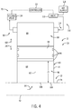
- FIG. 4 is an axial cross-sectional view of an embodiment of the adjustment mechanism 62 positioned on the resonator 13.
- the adjustment mechanism 62 includes the piston 66 driven to move axially in the first direction 100 and the second direction 102 along the resonator longitudinal axis 82 via a pneumatic system 110 of the actuator 70.
- the pneumatic system 110 includes a control valve 112 configured to direct supply air 114 (or any other suitable gas) from an air supply system 116 (e.g., an instrument air system, the air intake 30, etc.) into the inactive section 98 (e.g., chamber 99).
- an air supply system 116 e.g., an instrument air system, the air intake 30, etc.
- the pressure of the supply air 114 in the inactive section 98 may drive the piston 66 in the first direction 100, thereby decreasing the attenuation length 71 and reducing the volume of the active section 96.
- a release valve 118 may be configured to selectively release the supply air 114 from the inactive section 98 (e.g., chamber 99) and enable movement of the piston 66 in the second direction 102, e.g., by enabling pressure of the gas flow 84 entering the resonator chamber 64 to overcome the pressure of gas (e.g., air) in the chamber 99.
- the controller 52 may send a signal to the control valve 112 directing the control valve 112 to open and enable the supply air 114 to enter the inactive section 98.
- the controller 52 may send a signal to the release valve 118 to direct the release valve 118 to open to reduce the pressure in the inactive section 98 to enable movement of the piston 66 in the second direction 102. Accordingly, the controller 52 may send signals to the control valve 112 and the release valve 118 to adjust the axial position of the piston 66.
- the resonator 13 may be tunable before, during, and/or after operation (e.g., during maintenance) of the gas turbine system 10 to adjust for changing operating conditions (e.g., fuel composition, ambient temperature, etc.), gradual degradation and wear on the gas turbine system 10, and various changes in resonance frequencies in the gas turbine system 10.
- FIG. 5 is an axial cross-sectional view of an embodiment of the adjustment mechanism 62 positioned on the resonator 13.
- the adjustment mechanism 62 includes a gear set 120 having a first gear 122 (e.g., an elongated gear or geared shaft 68) interfacing with a second gear 124 (e.g., a circular gear).
- a first gear 122 e.g., an elongated gear or geared shaft 68
- second gear 124 e.g., a circular gear
- the actuator 70 drives rotation of the second gear 124
- gear teeth 126 of the second gear 124 engage with gear teeth 128 of the first gear 122 to transfer rotational movement of the second gear 124 into movement of the first gear 122, thereby driving the piston 66 to move along the tube 60 and vary the attenuation length 71.
- the gear set 120 may be a rack and pinion gear set, wherein the first gear 122 is a linear gear bar or rack and the second gear 124 is a circular gear or pinion.
- the actuator 70 e.g., a motor or drive 130
- gear teeth 126 of the pinion 124 engage with gear teeth (or threads) 128 of the rack 122 to transfer rotational movement of the pinion 124 into axial movement of the rack 122 and thus the piston 66.
- the gear set 120 may be a worm gear set, wherein the first gear 122 is a worm (e.g., an elongated threaded worm shaft 68) and the second gear 124 is a worm gear.
- the actuator 70 e.g., a motor or drive 130
- gear teeth 126 of the worm 124 engage with gear teeth (or threads) 128 of the worm 122 to transfer rotational movement of the worm gear 124 into movement of the worm 122 and thus the piston 66.
- the worm gear 124 may drive rotation of the worm 122, which then rotates threads within a threaded bore in the piston 66 to cause axial movement of the piston 66, or rotates the piston 66 along a threaded interface along the interior surface 104, or another suitable arrangement.
- the worm gear 124 may drive axial movement of the worm 122, thereby driving axial movement of the piston 66.
- the piston 66 may be moved in first and second directions 100, 102 in response to actuation of the gear set 120 by the actuator 70 (e.g., drive 130).
- the drive 130 may include an electric, pneumatic, and/or hydraulic drive or motor.
- the gear 124 may be coupled to the wall 72 of the resonator 13. However, in other embodiments, the gear 124 may include a separate housing coupled to the sidewall 74 of the combustor 12.
- the controller 52 may send a signal to the adjustment mechanism 62 instructing the adjustment mechanism 62 to change the attenuation length 71.
- FIG. 6 is an axial cross-sectional view of an embodiment of the adjustment mechanism 62 positioned on the resonator 13.
- the adjustment mechanism includes a biasing member 132 (e.g., a mechanical spring, opposing magnets that magnetically repel one another, a compressible fluid, or any combination thereof) and a compression member 134 (e.g., a secondary piston).
- the biasing member 132 is configured to drive the piston 66 in the first direction 100, radially inward toward the longitudinal axis 42 of the combustor 12.
- the biasing member 132 includes a spring having a spring constant configured to return a force substantially proportional to a change in length of the spring resulting from an opposing force.
- the spring constant may be particularly selected to enable compression of the spring 132, and therefore movement of the piston 66 in the second direction 102, to form a particularly selected attenuation length 71 based on an anticipated operating pressure of the combustor 12.
- the actuator 70 may be controlled to move the compression member 134 (e.g., moved to a different axial position) to pre-tension the biasing member 132, therefore limiting the total movement of the piston 66 (e.g., floating piston or spring biased piston) in the second direction 102.
- the actuator 70 may be controlled to move the compression member 134 in the first direction 100 and/or the second direction 102 to modify the volume of the inactive section 98.
- the attenuation length 71 may be controlled by the position of the compression member 134, the spring constant of the biasing member 132, and/or the operating pressure of the combustor 12.
- the controller 52 may be communicatively coupled to the actuator 70 to control movement of the compression member 134, and the controller 52 may be coupled to one or more sensors 136 associated with the compression member 134, the piston 66, or both.
- the sensors 136 may monitor pressures in the chambers 64 and/or 99, positions of the compression member 134 and/or the piston 66, or any combination thereof.
- the position and/or pressure feedback may enable the controller 52 to more accurately control the position of compression member 134 and/or the piston 66 via the actuator 70.
- FIG. 7 is a flow chart of an embodiment of a method 140 for controlling the attenuation length 71 of the resonators 13.
- the attenuation length 71 of the resonator 13 may be changed to adjust the frequency attenuated by the resonator 13.
- different frequencies of the gas flow 84 flowing into the resonators 13 via the first axial end 78 e.g., open end
- An initial attenuation length 71 is determined at block 142.
- the initial attenuation length 71 may be particularly selected based on anticipated operating conditions and/or frequencies of the gas flow 84 through the combustor 12.
- a first control signal is transmitted to the adjustment mechanism 62 from the controller 52 at block 144.
- an operator may input pre-set initial attenuation lengths 71 based on previous operation cycles of the gas turbine system 10.
- the controller 52 may transmit the first control signal to the adjustment mechanism 62 to instruct the adjustment mechanism 62 to drive movement of the piston 66 to establish the initial attenuation length 71 within the resonator 13.
- the first control signal is received by the adjustment mechanism 62 at block 146.
- the adjustment mechanism 62 may be communicatively coupled to the controller 52 to enable the adjustment mechanism 62 to initiate instructions received from the controller 52.
- the actuator 70 of the adjustment mechanism 62 may drive the piston 66 in the first direction 100.
- the controller 52 may receive an operating input from the sensors 48, 50 at block 148.
- the vibration sensor 50 may transmit a signal to the controller 52 indicative of an undesirable vibration in the combustor 12 (e.g., vibration in the fuel nozzle 16, vibration along the axial length 36 of the combustor 12, etc.).
- the controller 52 may transmit a second control signal to the adjustment mechanism 62 at block 150.
- the second control signal may be an instruction to change the attenuation length 71 based on the signal received from the sensors 48, 50.
- the adjustment mechanism 62 may receive the second control signal at block 152.
- the actuator 70 of the adjustment mechanism 62 may drive motion of the piston 66 in the second direction 102 to adjust the attenuation length 71 to an operating length, and thereby adjust the frequency that may be attenuated.
- the resonators 13 may be tuned before and/or during operation of the gas turbine system 10.
- the gas turbine system 10 may include resonators 13 positioned on the combustors 12 to attenuate frequencies in the gas flow 84 traveling through the combustors 12.
- the resonators 13 may be positioned circumferentially along the circumferential axis 46 of the combustors 12 and/or axially along the axial length 36 of the combustors 12.
- the resonators 13 may be configured to attenuate the frequency of the gas flow 84 related to the attenuation length 71 of the resonators 13.
- the resonators 13 may include the piston 66 configured to separate the resonators 13 into active sections 96 and inactive sections 98.
- the active sections 96 receive the gas flow 84, and the inactive sections 98 do not.
- the piston 66 is movable along the resonator longitudinal axis 82 to enable adjustment of the attenuation length 71 before, during, and/or after operation of the combustors 12.
- the resonators 13 may include the adjustment mechanisms 70 configured to drive movement of the piston 66 within the resonators 13, and thereby adjust the attenuation length 71.
- the adjustment mechanisms 70 may receive instructions from the controller 52 to set a desired attenuation length.
- the attenuation length 71 may be adjusted based on operating parameters received from the sensors 48, 50 distributed throughout the gas turbine system 10. Accordingly, the combustors 12 may be tuned before, during, and/or after operation to stabilize emissions, reduce combustion dynamics, stabilize combustion conditions, or the like.
Landscapes
- Engineering & Computer Science (AREA)
- Chemical & Material Sciences (AREA)
- Combustion & Propulsion (AREA)
- Mechanical Engineering (AREA)
- General Engineering & Computer Science (AREA)
- Soundproofing, Sound Blocking, And Sound Damping (AREA)
- Vibration Prevention Devices (AREA)
- Fluidized-Bed Combustion And Resonant Combustion (AREA)
- Feeding And Controlling Fuel (AREA)
Abstract
Description
- The subject matter disclosed herein relates to gas turbine systems, and more particularly, to a system and method for attenuating resonance.
- Gas turbine systems generally include a gas turbine engine having a compressor section, a combustor section, and a turbine section. The combustor section may include one or more combustors (e.g., combustion cans), which receive and combust a fuel with an oxidant (e.g., air) in a combustion chamber of each combustor. As combustion occurs in each combustor, hot combustion gases flow into and drive one or more turbine stages in the turbine section. Unfortunately, gas turbine systems may be susceptible to resonant behavior due to a variety of drivers, such as a resonant frequency of the oxidant, fuel, or other fluids supplied to the combustors. Over time, the resonant frequencies may change in the gas turbine system.
- Certain embodiments commensurate in scope with the originally claimed disclosure are summarized below. These embodiments are not intended to limit the scope of the claimed disclosure, but rather these embodiments are intended only to provide a brief summary of possible forms of the disclosure. Indeed, the disclosure may encompass a variety of forms that may be similar to or different from the embodiments set forth below.
- In a first embodiment, a system includes a combustor having a combustion chamber and a combustor supply passage configured to supply a fluid flow into the combustion chamber. The system also includes a resonator configured to receive at least a portion of the fluid flow. The resonator comprises a frequency adjuster configured to change an attenuation frequency of the resonator.
- In a second embodiment, a system includes a resonator configured to receive at least a portion of a fluid flow being supplied to a combustion chamber of a combustor. The resonator includes a frequency adjuster configured to change an attenuation frequency of the resonator. The system also includes a controller comprising a memory operatively coupled to a processor configured to store data and instructions. The controller is configured to transmit instructions to the frequency adjuster to change the attenuation frequency of the resonator.
- In a third embodiment, a method includes adjusting an attenuation frequency of a resonator coupled to a combustor supply passage configured to supply a fluid flow into a combustion chamber of a combustor. The resonator is configured to receive at least a portion of the fluid flow.
- These and other features, aspects, and advantages of the present disclosure will become better understood when the following detailed description is read with reference to the accompanying drawings in which like characters represent like parts throughout the drawings, wherein:
-
FIG. 1 is a schematic diagram of an embodiment of a gas turbine system having a resonance attenuation system with a plurality of resonators (e.g., adjustable resonators); -
FIG. 2 is a radial cross-sectional schematic view of an embodiment of a combustor having the resonance attenuation system with a plurality of resonators (e.g., adjustable resonators); -
FIG. 3 is an axial cross-sectional view of an embodiment of an adjustable resonator having an adjustment mechanism; -
FIG. 4 is an axial cross-sectional view of an embodiment of an adjustable resonator having an adjustment mechanism; -
FIG. 5 is an axial cross-sectional view of an embodiment of an adjustable resonator having an adjustment mechanism; -
FIG. 6 is an axial cross-sectional view of an embodiment of an adjustable resonator having an adjustment mechanism; and -
FIG. 7 is a flow chart of an embodiment of a method for adjusting an attenuation length of an adjustable resonator. - One or more specific embodiments of the present disclosure will be described below. In an effort to provide a concise description of these embodiments, all features of an actual implementation may not be described in the specification. It should be appreciated that in the development of any such actual implementation, as in any engineering or design project, numerous implementation-specific decisions must be made to achieve the developers' specific goals, such as compliance with system-related and business-related constraints, which may vary from one implementation to another. Moreover, it should be appreciated that such a development effort might be complex and time consuming, but would nevertheless be a routine undertaking of design, fabrication, and manufacture for those of ordinary skill having the benefit of this disclosure.
- When introducing elements of various embodiments of the present disclosure, the articles "a," "an," "the," and "said" are intended to mean that there are one or more of the elements. The terms "comprising," "including," and "having" are intended to be inclusive and mean that there may be additional elements other than the listed elements.
- Embodiments of the present disclosure are directed toward a system and method for adjusting combustion conditions by adjustably attenuating resonance of a flowing fluid (e.g., fuel, oxidant such as air, steam, inert gas such as nitrogen, combustion gases, or any combination thereof), thereby helping to increase flammability, improve stability of a flame, reduce emissions, and control combustion dynamics. For example, a gas turbine system may include a resonance attenuation system associated with one or more combustors, such as an annular combustor or a plurality of can-annular combustors circumferentially spaced about the rotational axis. The resonance attenuation system may include one or more resonators (e.g., adjustable resonators) associated with each combustor. For example, the resonator may be configured to attenuate or damp resonant frequencies associated with one or more fluid flows (e.g., gas and/or liquid flows), such as fluid flows upstream from, within, or downstream from the combustors. The fluid flows may include supplies of fuel (e.g., liquid and/or gas fuel), oxidant (e.g., oxygen, air, oxygen-rich air, oxygen-reduced air, or any other oxygen-containing mixture), steam, inert gas (e.g., nitrogen), recirculated exhaust gas, or any combination thereof. The fluid flows also may include combustion gases. However, in the following discussion and illustrated embodiments, the resonators are presented in context of oxidant flows (e.g., air flows) upstream, at, or within the combustors. For example, the resonators may be mounted in fluid communication with flows (e.g., oxidant flows) between a liner and flow sleeve of the combustor, through a head end chamber of the combustor, or any combination thereof. The resonators redirect at least a portion of the fluid flow along an attenuation length of the resonator to attenuate resonance frequencies and induce dampening. In certain embodiments, the attenuation length corresponds to a particularly selected frequency.
- The resonators may include adjustment mechanisms (e.g., frequency adjusters) configured to adjust one or more parameters of the resonators before, during, and/or after operation of the gas turbine system, thereby tailoring the resonators to resonant frequencies that may change with time and use of the gas turbine system. In certain embodiments, the resonators include quarter wavelength tube (QWT) resonators with an adjustable length. In other embodiments, the resonators may include other types of resonators with adjustments to vary the attenuation frequency of the resonators. For example, the adjustment mechanisms may enable adjustments to the volume (e.g., length) and thus attenuation frequency of the resonators during manufacturing, during operational testing and tuning, during normal operation, during downtime, during servicing or maintenance, or at any other suitable time. For example, the adjustment mechanisms may include manual adjusters and/or powered adjusters, such as automatic or semi-automatic adjusters. The powered adjusters also may be coupled to a control system and a monitoring system, thereby helping to enable automatic adjustments in response to changes in resonant frequencies in the gas turbine system. For example, the adjustment mechanisms may adjust the attenuation lengths based on signals received from sensors monitoring various operating conditions of the combustors. As a result, tuning of the resonators may stabilize emissions, reduce combustion dynamics, and/or stabilize combustion conditions.
- With the foregoing in mind,
FIG. 1 is a schematic diagram of an embodiment of agas turbine system 10 having a resonance attenuation system 11 (e.g., an adjustable resonance attenuation system) associated with one ormore combustors 12 of a combustor section. As discussed below, theresonance attenuation system 11 may include a plurality of resonators 13 (e.g., frequency adjustable resonators) directly coupled to thecombustors 12, supply passages leading to thecombustors 12, or any suitable location. For example, theresonance attenuation system 11 may includeresonators 13 coupled to ahead end section 14 and/or acombustion section 15 of eachcombustor 12, such as along an oxidant (e.g., air) flow path along thehead end section 14 and/orcombustion section 15. In certain embodiments, one ormore resonators 13 may be coupled to the oxidant flow path upstream offuel nozzles 16 mounted in thehead end section 14 of thecombustor 12. However, in certain embodiments, one ormore resonators 13 may be coupled to thefuel nozzles 16 in thehead end section 14 of thecombustor 12, one ormore resonators 13 may be fluidly coupled to acombustion chamber 17 inside of thecombustion section 15 downstream from thefuel nozzles 16, or any combination thereof. - The
combustor 12 may represent a single annular combustor, which extends circumferentially around a rotational axis of theturbine system 10. By further example, thecombustor 12 may represent a plurality of combustors (e.g., 2, 3, 4, 5, 6, 7, 8, 9, 10, or more) spaced circumferentially about the rotational axis of theturbine system 10. In certain embodiments, any number of combustors 12 (e.g., 1 to 20 or more) may be provided in theturbine system 10. Theresonators 13 of theresonance attenuation system 11 may be coupled to eachcombustor 12 in a uniform arrangement or a non-uniform arrangement, and the arrangement ofresonators 13 may be uniform or non-uniform from onecombustor 12 to another. For example, the number, spacing, and attenuation frequency of theresonators 12 may be the same or different from onecombustor 12 to another. - The
turbine system 10 may use liquid or gaseous fuel, such as natural gas and/or a synthetic gas, to drive theturbine system 10. In the illustrated embodiment, one or more fuel nozzles 16 (e.g., primary fuel nozzles, one or more quaternary injectors or pegs, and/or one or more late lean injectors) intake a supply of fuel 18 (e.g., a liquid fuel supply, a gaseous fuel supply, a liquid/gas mixture fuel supply). Each of the plurality ofcombustors 12 includes one or more fuel nozzles 16 (e.g., 1, 2, 3, 4, 5, 6, or more). Examples of thefuel 18 include, but are not limited to, hydrocarbon based liquid fuels, such as diesel fuel, jet fuel, gasoline, naphtha, fuel oil, liquefied petroleum gas, and so forth. Moreover, thefuel 18 may include a hydrocarbon based gaseous fuel, such as natural gas, synthetic gas, or the like. In the illustrated embodiment, theturbine system 10 may route thefuel 18 along afuel path 20 upstream of thefuel nozzles 16. In certain embodiments, thefuel nozzles 16 may include premix fuel nozzles and/or diffusion flame fuel nozzles. For example, thefuel nozzles 16 may premix thefuel 18 with oxidant (e.g., air) to generate a premix flame and/or separately flow thefuel 18 and oxidant into thecombustors 12 to generate a diffusion flame. - The
fuel 18 combusts with oxidant (e.g., air) in thecombustion chamber 17 within each of thecombustors 12, thereby creating hot pressurized exhaust gases. Thecombustors 12 direct the exhaust gases through a turbine orturbine section 22 toward anexhaust outlet 24. Theturbine section 22 may include one or more turbine stages (e.g., 1, 2, 3, 4, 5, 6, 7, 8, 9, 10, or more), each having a plurality of turbine blades coupled to a turbine rotor and shaft 26. As the exhaust gases pass through theturbine 22, the gases force the turbine blades to rotate the shaft 26 along a rotational axis of theturbine system 10. As illustrated, the shaft 26 is connected to various components of theturbine system 10, including a compressor orcompressor section 28. Thecompressor section 28 may include one or more compressor stages (e.g., 1, 2, 3, 4, 5, 6, 7, 8, 9, 10, or more), each having a plurality of compressor blades coupled to a compressor rotor and shaft, e.g., shaft 26. As the shaft 26 rotates, the blades within thecompressor 28 also rotate, thereby compressing oxidant (e.g., air) from an oxidant intake (e.g., air intake 30) through thecompressor 28 and into thefuel nozzles 16 and/orcombustors 12. The shaft 26 may also be connected to aload 31, which may be a vehicle or a stationary load, such as an electrical generator in a power plant or a propeller on an aircraft, for example. Theload 31 may include any suitable device capable of being powered by the rotational output of theturbine system 10. - In the following discussion, reference may be made to an axial direction or axis 42 (e.g., a longitudinal axis) of the
combustor 12, a radial direction oraxis 44 that extends radially relative to theaxis 42 of thecombustor 12, and a circumferential direction oraxis 46 that extends circumferentially about theaxis 42 of thecombustor 12. As discussed in detail below, in certain embodiments, theturbine system 10 includes adjustable resonators 13 (e.g., quarter wavelength tube resonators) positioned on thecombustors 12 at various locations, such as indicated byresonators resonators 13 may be coupled to each combustor 12 in fluid communication with a flow path 32 along the combustor 12 (e.g., external to the combustion chamber 17), ahead end chamber 33 in thehead end section 14, or a combination thereof. For example, the flow path 32 may be in fluid communication with thehead end chamber 33 and a compressor discharge chamber from thecompressor 28, thereby routing a compressed gas flow (e.g., compressed oxidant such as air) through the flow path 32 along the combustor (e.g., for cooling purposes), through thehead end chamber 33, and into the combustion chamber 17 (e.g., through the fuel nozzles 16) for purposes of combustion. In certain embodiments, the fluid flow through the flow path 32 and the head end chamber 33 (e.g., upstream of the fuel nozzles 16) may include or exclude any one or more of an oxidant (e.g., air, oxygen, oxygen-enriched air, oxygen-reduced air, etc.), exhaust gas recirculation (EGR) gas, steam, inert gas (e.g., nitrogen), and/or some amount of fuel (e.g., secondary fuel injection upstream of fuel nozzles 16). In certain embodiments, the flow path 32 may be disposed circumferentially about at least one wall defining a boundary of thecombustor 12, such as a first wall 34 (e.g., a combustion liner) disposed circumferentially about thecombustion chamber 17 and/or at least a portion of thehead end chamber 33. The flow path 32 also may be bounded by a second wall 35 (e.g., a flow sleeve) disposed circumferentially about thefirst wall 34. Thesecond wall 35 also may be disposed circumferentially about thehead end chamber 33 of thehead end section 14. - In the illustrated embodiment, the resonators 13 (e.g., 13A, 13B, 13C, and 13D) are coupled to at least one of the walls defining the boundary of the
combustor 12. For example, theresonator 13A is coupled to thewall 35 disposed about thehead end chamber 33, theresonator 13B is coupled to thewall 35 disposed about thehead end chamber 33 and/or flowpath 35 at a transition region between thecombustor section 15 and thehead end section 14, and theresonators wall 35 disposed theflow path 35, thefirst wall 34, and thecombustion chamber 17 of thecombustor section 15. Furthermore, as illustrated inFIG. 1 , theresonators 13 are arranged at different axial positions along anaxial length 36 of thecombustors 12, such as proximate to a first (e.g., upstream)axial end 38, a second (e.g., downstream)axial end 40, or at various intermediate positions between the first and second axial ends 38 and 40. However, in other embodiments, theresonators 13 may not be arranged along theaxial length 36 of thecombustors 12. For example, theresonators 13 may be positioned only near the firstaxial end 38 and/or thehead end section 14 to attenuate resonance frequencies in close proximity to (e.g., directly upstream from) thefuel nozzles 16 and the entry of fuel and oxidant into thecombustion chamber 17 of thecombustor 12. For example, in certain embodiments, the resonators 13 (e.g.,resonators 13A) may be positioned proximate to, axially upstream of, and/or axially overlapping with thefuel nozzles 16. Theresonators 13 also may be spaced apart from one another at different radial positions, different circumferential positions, different axial positions, or any combination thereof. In the illustrated embodiment, theresonators 13 are configured to attenuate resonance of the fluid flows from theair intake 30, e.g., after passing through thecompressor 28. - The
turbine system 10 also may have a variety of monitoring and control equipment associated with theresonators 13 of theresonance attenuation system 11. In the illustrated embodiment, theturbine system 10 may include one ormore sensors 48 to monitor the combustion process, oxidant flow, fuel flow, turbine speed, compressor feed, combustor temperature, combustion dynamics, acoustic noise, or a variety of other parameters of operation of theturbine system 10. For example, one or more vibration sensors 50 may be positioned on thecombustors 12 between the one ormore resonators 13. The vibration sensors 50 may detect vibrations within thecombustors 12. For example, vibration above a set value level may provide an indication that tuning theresonators 13 may provide improved combustion characteristics. As will be described below, in certain embodiments, theresonators 13 may be adjustable to enable tuning before, during, and/or after operation (e.g., during maintenance) of thegas turbine system 10. - The
sensors 48, 50 may be configured to send signals to a controller 52 (e.g., an electronic controller). In the illustrated embodiment, thecontroller 52 includes amemory 54 and aprocessor 56. Thememory 54 may be a mass storage device, a FLASH memory device, removable memory, or any other non-transitory computer-readable medium (e.g., not only a signal). Additionally and/or alternatively, the instructions may be stored in an additional suitable article of manufacture that includes at least one tangible, non-transitory computer-readable medium that at least collectively stores these instructions or routines in a manner similar to thememory 54 as described above. Thecontroller 52 may be configured to receive signals from thesensors 48, 50 indicative of operating parameters of the gas turbine system 10 (e.g., temperature, pressure, fuel/air ratio, acoustics, vibration). The signals may be evaluated by theprocessor 56 utilizing instructions stored on thememory 54. Additionally, thecontroller 52 may send signals to various components of the gas turbine system 10 (e.g., theresonators 13, theair intake 30, thecombustor 12, etc.) to adjust operating conditions of the gas turbine system 10 (e.g., including adjustments to the resonators 13) based on the signals received from thesensors 48, 50. -
FIG. 2 is a schematic radial cross-sectional view of an embodiment of thecombustor 12 havingresonators 13 disposed circumferentially 46 about thewall 35 of thecombustor 12. In the illustrated embodiment, eightresonators 13 are positioned substantially symmetrically (e.g., within approximately plus or minus 15 degrees) along a circumference 58 of thecombustor 12. However, in other embodiments, more offew resonators 13 may be included circumferentially 46 about thewall 35. For example, 1, 2, 3, 4, 5, 6, 7, 9, 10, 15, 20, 30, 40, 50 or any suitable number of resonators 13 (e.g., 1 to 100) may be positioned on thecombustor 12. Moreover, theresonators 13 may be positioned at different locations along the circumference 58 of thecombustor 12. For example, certain operating conditions may develop increased vibrations on one side of thecombustor 12. As a result,more resonators 13 may be placed on the side having increased vibrations to attenuate the air flow. As mentioned above, the vibration sensors 50 may be communicatively coupled to thecontroller 52 to send signals indicative of the operation of thecombustor 12. Moreover, in the illustrated embodiment, theresonators 13 are communicatively coupled to thecontroller 52. As will be described below, thecontroller 52 may instruct theresonators 13 to adjust before, during, and/or after operation to tune thecombustor 12. - During operation, the
resonators 13 are configured to receive a portion of the air flow from theair intake 30 and direct the portion of the air flow into the body of theresonators 13. For example, in the illustrated embodiment, eachresonator 13 includes aresonator tube 60 and an adjustment mechanism 62 (e.g., frequency adjuster) to vary aresonator chamber 64 in thetube 60, thereby adjusting an attenuation frequency of theresonator 13. Theadjustment mechanism 62 may include a plunger orpiston 66 disposed in thetube 60, a drive shaft orrod 68 coupled to thepiston 66, and anactuator 70 coupled to therod 68. Eachactuator 70 is in turn coupled to, and controlled by, thecontroller 52. Thetube 60 may be a hollow cylindrical tube defining a cylinder, while thepiston 66 may be a cylindrical piston. However, thetube 60 andpiston 66 may have other shapes. Thepiston 66 also may include one or more seals (e.g., annular seal rings) to seal against an inner wall of thetube 60. Theactuator 70 is configured to drive movement of therod 68, which in turn drives movement of thepiston 66 in thetube 60. Theactuator 70 may include a manual actuator, such as a hand wheel, a crank lever, a tool interface (e.g., a bolt head that interfaces with a wrench), or any other suitable manual actuation feature. Theactuator 70 also may include a powered actuator, such as an electric drive or motor, a pneumatic drive, a hydraulic drive, or any combination thereof. The actuator 70 (e.g., manual, powered, or both) may cause rotation and/or axial movement of therod 68, which in turn causes axial movement of thepiston 66 to vary anattenuation length 71 of theresonator chamber 64 within thetube 60 between thepiston 66 and an open inner end portion along thewall 35 of thecombustor 12. - As illustrated, the
attenuation length 71 of theresonator chamber 64 varies from oneresonator 13 to another about the circumference 58 of thewall 35 of thecombustor 12. Theattenuation length 71 of theresonator chamber 64 of each of theresonators 13 is particularly selected to attenuate (e.g., tune) a particular frequency or range of frequencies of the portion of the air flow from theair intake 30. Accordingly, as shown in the illustrated embodiment, theresonators 13 may have different attenuation lengths to attenuate different frequencies. However, in the illustrated embodiment, an overall length and diameter of eachtube 60 may be constant (or uniform) among all of theresonators 13, thereby enabling simplified construction of theresonator 13 while still enabling attenuation of different frequencies for thecombustor 12. As a result, similar parts may be utilized to manufacture and service theresonators 13. Moreover, theresonators 13 may be utilized over a larger range of frequencies due to their adjustability, thereby increasing their utility as conditions and resonance frequencies change in thegas turbine system 10. -
FIG. 3 is an axial cross-sectional side view of an embodiment of theresonator 13 having anadjustment mechanism 62. In the illustrated embodiment, thetube 60 of theresonator 13 includes a cylinder defined by a generallycylindrical wall 72. However, in other embodiments, thewall 72 may be elliptical, polygonal, or the like. Thewall 72 may be configured to couple to asidewall 74 of thecombustor 12, such as thewall 35 illustrated inFIGS. 1 and2 . For example, thewall 72 may include threads that engage mating threads in thesidewall 74, thereby coupling theresonator 13 to thecombustor 12. However, in other embodiments, thewall 72 may be welded, bolted, clamped, or otherwise coupled to thesidewall 74 with a removable coupling or a fixed coupling. In some embodiments, thewall 72 of thetube 60 may be integrally formed as one-piece with thesidewall 74 of thecombustor 12. - In the illustrated embodiment, the
resonator 13 has abody length 76, e.g., a total length of thetube 60, extending from a first axial end 78 (e.g., end opening or face) to a second axial end 80 (e.g., end opening, sealed end, or face) along a resonatorlongitudinal axis 82. In the illustrated embodiment, the resonatorlongitudinal axis 82 is perpendicular or substantially perpendicular (e.g., 90 degrees plus orminus 1, 2, 3, 4, 5, 6, 7, 8, 9, or 10 degrees) relative to thelongitudinal axis 42 of thecombustor 12. However, in other embodiments, the resonatorlongitudinal axis 82 may be positioned crosswise at an angle (e.g., 10 to 80, 20 to 70, 30 to 60, or 40 to 50 degrees) relative to thelongitudinal axis 42. In operation, the first axial end 78 (e.g., end opening) of thetube 60 receives a gas flow 84 (e.g., oxidant such as air, EGR gas, steam, inert gas such as nitrogen, gaseous fuel, fuel/air mixtures, etc.) from a fluid supply directed to thecombustor 12 and directs thegas flow 84 into theresonator 13. In certain embodiments, thegas flow 84 excludes combustion gases directly from thecombustion chamber 17, but may include any fluid flows directed into thecombustion chamber 17 such as through thehead end section 14. In other embodiments, thegas flow 84 may include the combustion gases directly from thecombustion chamber 17. However, in the illustrated embodiment, thegas flow 84 may include at least a substantial amount (e.g., greater than 50, 60, 70, 80, 90, or 95 percent by volume) oxidant flow from theair intake 30, e.g., after compression by thecompressor 28. As mentioned above, theresonator 13 is configured to reduce resonance in the combustion system by attenuating any resonance frequencies in thegas flow 84. In the illustrated embodiment, the frequency at which theresonator 13 attenuates thegas flow 84 is directly related to theattenuation length 71 of theresonator 13. Theattenuation length 71 represents the distance that thegas flow 84 may travel through theresonator 13 before being reflected back toward thecombustor 12. In other words, the attenuate length 86 is the distance between the firstaxial end 78 and thepiston 66 in thetube 60 of theresonator 13. In certain embodiments, theattenuation length 71 may be varied continuously and/or incrementally (e.g., in incremental steps) between 0 and 100, 5 and 95, 10 and 90, 15 and 85, and 20 and 80 percent of thebody length 76. For example, theattenuation length 71 may be varied in incremental steps of approximately 1, 2, 3, 4, 5, 6, 7, 8, 9, or 10 percent of thetotal body length 76 of thetube 60. As will be described below, theattenuation length 71 of theresonator 13 may be adjusted to enable attenuation over a range of frequencies. - Because it may be desirable to attenuate a range of frequencies in the
combustor 12, the adjustment mechanism 62 (e.g.,piston 66,rod 68, and actuator 70) is configured to adjust theattenuation length 71 of theresonator 13. In the illustrated embodiment, theadjustment mechanism 62 includes thepiston 66, therod 68, and theactuator 70. For example, theactuator 70 may include a drive or motor (e.g., electric, pneumatic, and/or hydraulic) that drives therod 68 to change an axial position of thepiston 66 along the resonatorlongitudinal axis 82. As a result, thepiston 66 in thetube 60 of theresonator 13 has a different axial position, thereby adjusting theattenuation length 71. In the illustrated embodiment, thepiston 66 includes seals 94 (e.g., annular seal rings) configured to fluidly isolate an active section 96 (e.g., resonator chamber 64) from an inactive section 98 (e.g., opposing chamber 99). Theactive section 96 may receive thegas flow 84, while theinactive section 98 may not receive thegas flow 84 due to blockage provided by thepiston 66 and sealing provided by theseals 94. - The
adjustment mechanism 62 may adjust theattenuation length 71, and therefore respective volumes of theactive section 96 and theinactive section 98, via theactuator 70 driving axial motion of thepiston 66 along the resonatorlongitudinal axis 82. That is, theadjustment mechanism 62 may drive movement of thepiston 66 in afirst direction 100 radially inward toward thelongitudinal axis 42 of thecombustor 12 or in asecond direction 102 radially outward away from thelongitudinal axis 42 of thecombustor 12. For example, theactuator 70 may cause axial translation (i.e., axial movement without rotation) of therod 68, thereby driving axial translation of thepiston 66 in thetube 60. By further example, the actuator may cause rotation (with or without axial movement) of therod 68, thereby driving axial movement of thepiston 66 in the tube 60 (e.g., by threading therod 68 through a threaded receptacle in thepiston 66 while thepiston 66 is blocked from rotating via an axial guide feature). By further example, theactuator 70 may drive rotation of thepiston 66 to engage with corresponding threads, ridges, or gear teeth on aninterior surface 104 of thewall 72, thereby causing thepiston 66 to threadingly rotate and axially move along thewall 72 to change its axial position. Regardless of the specific configuration of theactuation mechanism 62, thepiston 66 moves in thetube 60 to vary theattenuation length 71, thereby adjusting theresonator 13 to attenuate different frequencies without replacing theresonator 13. Moreover, theadjustment mechanism 62 may adjust the attenuation length 71 (e.g., via manual adjustments and/or control by the controller 52) during operation of thegas turbine system 10, thereby reducing system downtimes and enabling real-time or near real-time tuning of thegas turbine system 10. - In the illustrated embodiment, the
resonator 13 includes aplate 106 at the firstaxial end 78. Theplate 106 may include perforations 108 (e.g., orifices, openings, slots, etc.) to restrict and/or throttle thegas flow 84 entering theactive section 96 of theresonator 13. For example, theplate 106 and theperforations 108 may decrease the cross-sectional area of openings through the firstaxial end 78, thereby reducing thegas flow 84 entering theactive section 96. Moreover, theperforations 108 in theplate 106 enable viscous damping of thegas flow 84 entering theresonator 13 by forcing thegas flow 84 through theperforations 108 before entering theresonator 13, resulting in a loss of energy to thegas flow 84. For example, the pressure of thegas flow 84 may decrease as thegas flow 84 enters theresonator 13 due to the pressure drop across theplate 106. -
FIG. 4 is an axial cross-sectional view of an embodiment of theadjustment mechanism 62 positioned on theresonator 13. In the illustrated embodiment, theadjustment mechanism 62 includes thepiston 66 driven to move axially in thefirst direction 100 and thesecond direction 102 along the resonatorlongitudinal axis 82 via apneumatic system 110 of theactuator 70. Thepneumatic system 110 includes acontrol valve 112 configured to direct supply air 114 (or any other suitable gas) from an air supply system 116 (e.g., an instrument air system, theair intake 30, etc.) into the inactive section 98 (e.g., chamber 99). The pressure of thesupply air 114 in theinactive section 98 may drive thepiston 66 in thefirst direction 100, thereby decreasing theattenuation length 71 and reducing the volume of theactive section 96. Additionally, arelease valve 118 may be configured to selectively release thesupply air 114 from the inactive section 98 (e.g., chamber 99) and enable movement of thepiston 66 in thesecond direction 102, e.g., by enabling pressure of thegas flow 84 entering theresonator chamber 64 to overcome the pressure of gas (e.g., air) in thechamber 99. In the illustrated embodiment, thecontroller 52 may send a signal to thecontrol valve 112 directing thecontrol valve 112 to open and enable thesupply air 114 to enter theinactive section 98. Moreover, thecontroller 52 may send a signal to therelease valve 118 to direct therelease valve 118 to open to reduce the pressure in theinactive section 98 to enable movement of thepiston 66 in thesecond direction 102. Accordingly, thecontroller 52 may send signals to thecontrol valve 112 and therelease valve 118 to adjust the axial position of thepiston 66. As a result, theresonator 13 may be tunable before, during, and/or after operation (e.g., during maintenance) of thegas turbine system 10 to adjust for changing operating conditions (e.g., fuel composition, ambient temperature, etc.), gradual degradation and wear on thegas turbine system 10, and various changes in resonance frequencies in thegas turbine system 10. -
FIG. 5 is an axial cross-sectional view of an embodiment of theadjustment mechanism 62 positioned on theresonator 13. In the illustrated embodiment, theadjustment mechanism 62 includes agear set 120 having a first gear 122 (e.g., an elongated gear or geared shaft 68) interfacing with a second gear 124 (e.g., a circular gear). As the actuator 70 (e.g., a motor or drive 130) drives rotation of thesecond gear 124,gear teeth 126 of thesecond gear 124 engage withgear teeth 128 of thefirst gear 122 to transfer rotational movement of thesecond gear 124 into movement of thefirst gear 122, thereby driving thepiston 66 to move along thetube 60 and vary theattenuation length 71. - For example, the gear set 120 may be a rack and pinion gear set, wherein the
first gear 122 is a linear gear bar or rack and thesecond gear 124 is a circular gear or pinion. Accordingly, as the actuator 70 (e.g., a motor or drive 130) drives rotation of thepinion 124,gear teeth 126 of thepinion 124 engage with gear teeth (or threads) 128 of therack 122 to transfer rotational movement of thepinion 124 into axial movement of therack 122 and thus thepiston 66. - By further example, the gear set 120 may be a worm gear set, wherein the
first gear 122 is a worm (e.g., an elongated threaded worm shaft 68) and thesecond gear 124 is a worm gear. Accordingly, as the actuator 70 (e.g., a motor or drive 130) drives rotation of theworm gear 124,gear teeth 126 of theworm 124 engage with gear teeth (or threads) 128 of theworm 122 to transfer rotational movement of theworm gear 124 into movement of theworm 122 and thus thepiston 66. For example, theworm gear 124 may drive rotation of theworm 122, which then rotates threads within a threaded bore in thepiston 66 to cause axial movement of thepiston 66, or rotates thepiston 66 along a threaded interface along theinterior surface 104, or another suitable arrangement. By further example, theworm gear 124 may drive axial movement of theworm 122, thereby driving axial movement of thepiston 66. - As a result, the
piston 66 may be moved in first andsecond directions drive 130 may include an electric, pneumatic, and/or hydraulic drive or motor. As shown, thegear 124 may be coupled to thewall 72 of theresonator 13. However, in other embodiments, thegear 124 may include a separate housing coupled to thesidewall 74 of thecombustor 12. As described above, thecontroller 52 may send a signal to theadjustment mechanism 62 instructing theadjustment mechanism 62 to change theattenuation length 71. -
FIG. 6 is an axial cross-sectional view of an embodiment of theadjustment mechanism 62 positioned on theresonator 13. In the illustrated embodiment, the adjustment mechanism includes a biasing member 132 (e.g., a mechanical spring, opposing magnets that magnetically repel one another, a compressible fluid, or any combination thereof) and a compression member 134 (e.g., a secondary piston). The biasingmember 132 is configured to drive thepiston 66 in thefirst direction 100, radially inward toward thelongitudinal axis 42 of thecombustor 12. In the illustrated embodiment, the biasingmember 132 includes a spring having a spring constant configured to return a force substantially proportional to a change in length of the spring resulting from an opposing force. For example, the spring constant may be particularly selected to enable compression of thespring 132, and therefore movement of thepiston 66 in thesecond direction 102, to form a particularly selectedattenuation length 71 based on an anticipated operating pressure of thecombustor 12. Additionally, theactuator 70 may be controlled to move the compression member 134 (e.g., moved to a different axial position) to pre-tension the biasingmember 132, therefore limiting the total movement of the piston 66 (e.g., floating piston or spring biased piston) in thesecond direction 102. For example, theactuator 70 may be controlled to move thecompression member 134 in thefirst direction 100 and/or thesecond direction 102 to modify the volume of theinactive section 98. As a result, theattenuation length 71 may be controlled by the position of thecompression member 134, the spring constant of the biasingmember 132, and/or the operating pressure of thecombustor 12. In certain embodiments, thecontroller 52 may be communicatively coupled to theactuator 70 to control movement of thecompression member 134, and thecontroller 52 may be coupled to one ormore sensors 136 associated with thecompression member 134, thepiston 66, or both. For example, thesensors 136 may monitor pressures in thechambers 64 and/or 99, positions of thecompression member 134 and/or thepiston 66, or any combination thereof. The position and/or pressure feedback may enable thecontroller 52 to more accurately control the position ofcompression member 134 and/or thepiston 66 via theactuator 70. -
FIG. 7 is a flow chart of an embodiment of amethod 140 for controlling theattenuation length 71 of theresonators 13. As mentioned above, theattenuation length 71 of theresonator 13 may be changed to adjust the frequency attenuated by theresonator 13. As a result, different frequencies of thegas flow 84 flowing into theresonators 13 via the first axial end 78 (e.g., open end) may be attenuated before, during, and/or after operation of thegas turbine system 10. Aninitial attenuation length 71 is determined atblock 142. For example, theinitial attenuation length 71 may be particularly selected based on anticipated operating conditions and/or frequencies of thegas flow 84 through thecombustor 12. A first control signal is transmitted to theadjustment mechanism 62 from thecontroller 52 atblock 144. For example, an operator may input pre-setinitial attenuation lengths 71 based on previous operation cycles of thegas turbine system 10. Thecontroller 52 may transmit the first control signal to theadjustment mechanism 62 to instruct theadjustment mechanism 62 to drive movement of thepiston 66 to establish theinitial attenuation length 71 within theresonator 13. The first control signal is received by theadjustment mechanism 62 atblock 146. As described above, theadjustment mechanism 62 may be communicatively coupled to thecontroller 52 to enable theadjustment mechanism 62 to initiate instructions received from thecontroller 52. For example, upon receipt of instructions to set thepiston 66 at theinitial attenuation length 71, theactuator 70 of theadjustment mechanism 62 may drive thepiston 66 in thefirst direction 100. Thecontroller 52 may receive an operating input from thesensors 48, 50 atblock 148. For example, the vibration sensor 50 may transmit a signal to thecontroller 52 indicative of an undesirable vibration in the combustor 12 (e.g., vibration in thefuel nozzle 16, vibration along theaxial length 36 of thecombustor 12, etc.). Thecontroller 52 may transmit a second control signal to theadjustment mechanism 62 atblock 150. For example, the second control signal may be an instruction to change theattenuation length 71 based on the signal received from thesensors 48, 50. Theadjustment mechanism 62 may receive the second control signal atblock 152. For example, theactuator 70 of theadjustment mechanism 62 may drive motion of thepiston 66 in thesecond direction 102 to adjust theattenuation length 71 to an operating length, and thereby adjust the frequency that may be attenuated. As a result, theresonators 13 may be tuned before and/or during operation of thegas turbine system 10. - As described in detail above, the
gas turbine system 10 may includeresonators 13 positioned on thecombustors 12 to attenuate frequencies in thegas flow 84 traveling through thecombustors 12. For example, theresonators 13 may be positioned circumferentially along thecircumferential axis 46 of thecombustors 12 and/or axially along theaxial length 36 of thecombustors 12. In certain embodiments, theresonators 13 may be configured to attenuate the frequency of thegas flow 84 related to theattenuation length 71 of theresonators 13. For example, in certain embodiments, theresonators 13 may include thepiston 66 configured to separate theresonators 13 intoactive sections 96 andinactive sections 98. Theactive sections 96 receive thegas flow 84, and theinactive sections 98 do not. Moreover, thepiston 66 is movable along the resonatorlongitudinal axis 82 to enable adjustment of theattenuation length 71 before, during, and/or after operation of thecombustors 12. For example, theresonators 13 may include theadjustment mechanisms 70 configured to drive movement of thepiston 66 within theresonators 13, and thereby adjust theattenuation length 71. Furthermore, theadjustment mechanisms 70 may receive instructions from thecontroller 52 to set a desired attenuation length. Moreover, theattenuation length 71 may be adjusted based on operating parameters received from thesensors 48, 50 distributed throughout thegas turbine system 10. Accordingly, thecombustors 12 may be tuned before, during, and/or after operation to stabilize emissions, reduce combustion dynamics, stabilize combustion conditions, or the like. - This written description uses examples to disclose various embodiments of the disclosure, and also to enable any person skilled in the art to practice the disclosure, including making and using any devices or systems and performing any incorporated methods. The patentable scope of the disclosure is defined by the claims, and may include other examples that occur to those skilled in the art. Such other examples are intended to be within the scope of the claims if they have structural elements that do not differ from the literal language of the claims, or if they include equivalent structural elements with insubstantial differences from the literal language of the claims.
- Various aspects and embodiments of the present invention are defined by the following numbered clauses:
- 1. A system comprising:
- a combustor having a combustion chamber and a combustor supply passage configured to supply a fluid flow into the combustion chamber; and
- a resonator configured to receive at least a portion of the fluid flow, wherein the resonator comprises a frequency adjuster configured to change an attenuation frequency of the resonator.
- 2. The system of clause 1, wherein the combustor comprises a gas turbine combustor.
- 3. The system of any preceding clause, comprising a gas turbine engine having the gas turbine combustor.
- 4. The system of any preceding clause, wherein the combustor supply passage comprises a head end chamber of the gas turbine combustor, a passage between a combustion liner and a flow sleeve, or a combination thereof.
- 5. The system of any preceding clause, wherein the fluid flow comprises an oxidant.
- 6. The system of any preceding clause, wherein the frequency adjuster comprises a piston disposed in a tube of the resonator.
- 7. The system of any preceding clause, wherein the frequency adjuster comprises an actuator configured to adjust a position of the piston in the tube to vary a resonator chamber of the resonator.
- 8. The system of any preceding clause, wherein the actuator comprises an electric drive, a pneumatic drive, a hydraulic drive, or a combination thereof.
- 9. The system of any preceding clause, wherein the actuator comprises a pneumatic system having a gas supply configured to supply a gas to vary a position of the piston, a control valve configured to control the supply of the gas to bias the piston in a first direction, and a release valve configured to control a release of the gas to enable movement of the piston in a second direction.
- 10. The system of any preceding clause, wherein the frequency adjuster comprises a spring configured to bias the piston.
- 11. The system of any preceding clause, wherein the frequency adjuster comprises a compression member configured to move relative to the spring and the piston.
- 12. The system of any preceding clause, wherein the frequency adjuster comprises a worm gear set, a rack and pinion gear set, or a combination thereof, between the piston and the actuator.
- 13. The system of any preceding clause, comprising a plate having perforations positioned at a first axial end of the resonator, wherein the perforations are configured to induce viscous damping of the fluid flow entering the resonator.
- 14. The system of any preceding clause, comprising a controller communicatively coupled to the frequency adjuster and configured to send instructions to the frequency adjuster to change the attenuation frequency of the resonator.
- 15. A system comprising:
- a resonator configured to receive at least a portion of a fluid flow being supplied to a combustion chamber of a combustor, wherein the resonator comprises a frequency adjuster configured to change an attenuation frequency of the resonator; and
- a controller comprising a memory operatively coupled to a processor configured to store data and instructions, wherein the controller is configured to transmit instructions to the frequency adjuster to change the attenuation frequency of the resonator.
- 16. The system of any preceding clause, comprising a sensor communicatively coupled to the controller, wherein the sensor sends a signal to the controller indicative of an operating parameter of a gas turbine system having the combustor and the resonator, and the controller is configured to instruct the frequency adjuster to change the attenuation frequency based on the operating parameter.
- 17. The system of any preceding clause, wherein the frequency adjuster comprises a piston disposed in a tube of the resonator, and an actuator configured to adjust a position of the piston in the tube to vary a resonator chamber of the resonator, wherein the controller is communicatively coupled to the actuator.
- 18. A method comprising:
- adjusting an attenuation frequency of a resonator coupled to a combustor supply passage configured to supply a fluid flow into a combustion chamber of a combustor, wherein the resonator is configured to receive at least a portion of the fluid flow.
- 19. The method of any preceding clause, wherein adjusting comprises actuating movement of a piston disposed in a tube of the resonator to vary a length of a resonator chamber.
- 20. The method of any preceding clause, wherein adjusting comprises responding to sensor feedback indicative of at least one operating parameter of a gas turbine system having the combustor and the resonator.
- 21. The method of any preceding clause, wherein the fluid flow comprises an oxidant flow being supplied to the combustion chamber of the combustor.
Claims (15)
- A system comprising:a combustor having a combustion chamber and a combustor supply passage configured to supply a fluid flow into the combustion chamber; anda resonator configured to receive at least a portion of the fluid flow, wherein the resonator comprises a frequency adjuster configured to change an attenuation frequency of the resonator.
- The system of claim 1, wherein the combustor comprises a gas turbine combustor.
- The system of claim 2, wherein the combustor supply passage comprises a head end chamber of the gas turbine combustor, a passage between a combustion liner and a flow sleeve, or a combination thereof.
- The system of claim 1, 2 or 3, wherein the fluid flow comprises an oxidant.
- The system of any preceding claim, wherein the frequency adjuster comprises a piston disposed in a tube of the resonator.
- The system of claim 5, wherein the frequency adjuster comprises an actuator configured to adjust a position of the piston in the tube to vary a resonator chamber of the resonator.
- The system of claim 5, wherein the actuator comprises a pneumatic system having a gas supply configured to supply a gas to vary a position of the piston, a control valve configured to control the supply of the gas to bias the piston in a first direction, and a release valve configured to control a release of the gas to enable movement of the piston in a second direction.
- The system of any preceding claim, comprising a plate having perforations positioned at a first axial end of the resonator, wherein the perforations are configured to induce viscous damping of the fluid flow entering the resonator.
- The system of any preceding claim, comprising a controller communicatively coupled to the frequency adjuster and configured to send instructions to the frequency adjuster to change the attenuation frequency of the resonator.
- A system comprising:a resonator configured to receive at least a portion of a fluid flow being supplied to a combustion chamber of a combustor, wherein the resonator comprises a frequency adjuster configured to change an attenuation frequency of the resonator; anda controller comprising a memory operatively coupled to a processor configured to store data and instructions, wherein the controller is configured to transmit instructions to the frequency adjuster to change the attenuation frequency of the resonator.
- The system of claim 10, comprising a sensor communicatively coupled to the controller, wherein the sensor sends a signal to the controller indicative of an operating parameter of a gas turbine system having the combustor and the resonator, and the controller is configured to instruct the frequency adjuster to change the attenuation frequency based on the operating parameter.
- The system of claim 10 or 11, wherein the frequency adjuster comprises a piston disposed in a tube of the resonator, and an actuator configured to adjust a position of the piston in the tube to vary a resonator chamber of the resonator, wherein the controller is communicatively coupled to the actuator.
- A method comprising:adjusting an attenuation frequency of a resonator coupled to a combustor supply passage configured to supply a fluid flow into a combustion chamber of a combustor, wherein the resonator is configured to receive at least a portion of the fluid flow.
- The method of claim 13, wherein adjusting comprises actuating movement of a piston disposed in a tube of the resonator to vary a length of a resonator chamber.
- The method of claim 13 or 14, wherein adjusting comprises responding to sensor feedback indicative of at least one operating parameter of a gas turbine system having the combustor and the resonator.
Applications Claiming Priority (1)
| Application Number | Priority Date | Filing Date | Title |
|---|---|---|---|
| US14/680,995 US10088165B2 (en) | 2015-04-07 | 2015-04-07 | System and method for tuning resonators |
Publications (2)
| Publication Number | Publication Date |
|---|---|
| EP3101345A2 true EP3101345A2 (en) | 2016-12-07 |
| EP3101345A3 EP3101345A3 (en) | 2017-02-15 |
Family
ID=55650342
Family Applications (1)
| Application Number | Title | Priority Date | Filing Date |
|---|---|---|---|
| EP16163676.6A Withdrawn EP3101345A3 (en) | 2015-04-07 | 2016-04-04 | System and method for tuning resonators |
Country Status (6)
| Country | Link |
|---|---|
| US (1) | US10088165B2 (en) |
| EP (1) | EP3101345A3 (en) |
| JP (1) | JP6816968B2 (en) |
| KR (1) | KR102537730B1 (en) |
| CN (1) | CN106051766B (en) |
| BR (1) | BR102016007571A2 (en) |
Families Citing this family (21)
| Publication number | Priority date | Publication date | Assignee | Title |
|---|---|---|---|---|
| US10415471B2 (en) | 2016-11-30 | 2019-09-17 | United Technologies Corporation | Variable volume acoustic damper |
| US10941708B2 (en) | 2017-03-07 | 2021-03-09 | Raytheon Technologies Corporation | Acoustically damped gas turbine engine |
| US10428685B2 (en) | 2017-03-07 | 2019-10-01 | United Technologies Corporation | Flutter inhibiting intake for gas turbine propulsion system |
| US10539156B2 (en) * | 2017-03-07 | 2020-01-21 | United Technologies Corporation | Variable displacement flutter damper for a turbofan engine |
| US10422280B2 (en) | 2017-03-07 | 2019-09-24 | United Technologies Corporation | Fan flutter suppression system |
| US10612464B2 (en) | 2017-03-07 | 2020-04-07 | United Technologies Corporation | Flutter inhibiting intake for gas turbine propulsion system |
| US10619566B2 (en) | 2017-03-07 | 2020-04-14 | United Technologies Corporation | Flutter damper for a turbofan engine |
| US10415506B2 (en) | 2017-03-07 | 2019-09-17 | United Technologies Corporation | Multi degree of freedom flutter damper |
| KR101942001B1 (en) | 2017-08-11 | 2019-01-25 | 충남대학교산학협력단 | Frequency variable type burner |
| CN107781847B (en) * | 2017-09-22 | 2023-04-11 | 中国华能集团公司 | Dual gas fuel combustor and method of operating gas turbine using the same |
| US10677163B2 (en) * | 2017-12-06 | 2020-06-09 | General Electric Company | Noise attenuation structures |
| CN108412581B (en) * | 2018-04-23 | 2023-10-13 | 吉林大学 | A variable volume through-impedance composite silencer and its control method |
| EP3760925B1 (en) * | 2019-07-01 | 2024-12-18 | Ansaldo Energia Switzerland AG | Combustor assembly of a gas turbine assembly comprising a damper and method for manufacturing |
| CN112031955B (en) * | 2020-09-11 | 2021-06-29 | 河北工业大学 | Intake Regulator for High Pressure Direct Injection Natural Gas Engine Based on Variable Coherence Wavelength |
| US11798771B2 (en) | 2021-02-01 | 2023-10-24 | Toyota Motor Engineering & Manufacturing North America, Inc. | Adjustable frequency tube resonators |
| CN113108317B (en) * | 2021-05-13 | 2023-03-14 | 中国联合重型燃气轮机技术有限公司 | Gas turbine, combustion chamber and combustion control method thereof |
| CN113719861B (en) * | 2021-09-10 | 2022-12-06 | 中国联合重型燃气轮机技术有限公司 | Combustion chamber and gas turbine with same |
| CN113803744B (en) * | 2021-09-27 | 2023-03-10 | 中国联合重型燃气轮机技术有限公司 | Combustion chamber feeding device and feeding system |
| US12037952B2 (en) * | 2022-01-04 | 2024-07-16 | General Electric Company | Systems and methods for providing output products to a combustion chamber of a gas turbine engine |
| GB2629198A (en) * | 2023-04-21 | 2024-10-23 | Bae Systems Plc | Acoustic control system, active acoustic control system, and method |
| CN118856366B (en) * | 2024-08-09 | 2025-02-07 | 无锡明阳氢燃动力科技有限公司 | Combustion chamber for suppressing thermoacoustic oscillation and wavelength tube adjustment method for pure hydrogen gas turbine |
Family Cites Families (54)
| Publication number | Priority date | Publication date | Assignee | Title |
|---|---|---|---|---|
| US2072826A (en) | 1935-06-05 | 1937-03-02 | Hartford Empire Co | Article transferring mechanism |
| US5943866A (en) | 1994-10-03 | 1999-08-31 | General Electric Company | Dynamically uncoupled low NOx combustor having multiple premixers with axial staging |
| US6464489B1 (en) * | 1997-11-24 | 2002-10-15 | Alstom | Method and apparatus for controlling thermoacoustic vibrations in a combustion system |
| DE10026121A1 (en) * | 2000-05-26 | 2001-11-29 | Alstom Power Nv | Device for damping acoustic vibrations in a combustion chamber |
| US6530221B1 (en) | 2000-09-21 | 2003-03-11 | Siemens Westinghouse Power Corporation | Modular resonators for suppressing combustion instabilities in gas turbine power plants |
| DE10058688B4 (en) | 2000-11-25 | 2011-08-11 | Alstom Technology Ltd. | Damper arrangement for the reduction of combustion chamber pulsations |
| AU2002252259B2 (en) | 2001-03-08 | 2007-08-02 | California Institute Of Technology | Real-time spatio-temporal coherence estimation for autonomous mode identification and invariance tracking |
| EP1342952A1 (en) * | 2002-03-07 | 2003-09-10 | Siemens Aktiengesellschaft | Burner, process for operating a burner and gas turbine |
| US6820431B2 (en) | 2002-10-31 | 2004-11-23 | General Electric Company | Acoustic impedance-matched fuel nozzle device and tunable fuel injection resonator assembly |
| US7693147B2 (en) | 2003-04-04 | 2010-04-06 | General Electric Company | Method and apparatus for remotely monitoring gas turbine combustion dynamics |
| JP4177728B2 (en) * | 2003-07-31 | 2008-11-05 | 東京電力株式会社 | Combustion vibration suppression device and combustion vibration suppression method |
| ITTO20031013A1 (en) * | 2003-12-16 | 2005-06-17 | Ansaldo Energia Spa | THERMO ACOUSTIC INSTABILITY DAMPING SYSTEM IN A COMBUSTOR DEVICE FOR A GAS TURBINE. |
| US7337057B2 (en) | 2004-05-28 | 2008-02-26 | General Electric Company | Methods and apparatus for predicting and/or for avoiding lean blow-outs |
| US20060041368A1 (en) | 2004-08-18 | 2006-02-23 | General Electric Company | Systems, Methods and Computer Program Products for Remote Monitoring of Turbine Combustion Dynamics |
| US7278266B2 (en) | 2004-08-31 | 2007-10-09 | General Electric Company | Methods and apparatus for gas turbine engine lean blowout avoidance |
| JP3111818U (en) * | 2005-03-29 | 2005-07-28 | 甫 宮管 | Stone splitting machine |
| US7451601B2 (en) | 2005-05-10 | 2008-11-18 | General Electric Company | Method of tuning individual combustion chambers in a turbine based on a combustion chamber stratification index |
| US7739999B2 (en) | 2005-11-23 | 2010-06-22 | Gm Global Technology Operations, Inc. | Method and apparatus to control combustion in a multi-cylinder homogeneous charge compression-ignition engine |
| US7805922B2 (en) | 2006-02-09 | 2010-10-05 | Siemens Energy, Inc. | Fuel flow tuning for a stage of a gas turbine engine |
| US7523614B2 (en) | 2006-02-27 | 2009-04-28 | Mitsubishi Heavy Industries, Ltd. | Combustor |
| US7503177B2 (en) | 2006-03-17 | 2009-03-17 | Siemens Energy, Inc. | Combustion dynamics monitoring |
| US8127546B2 (en) | 2007-05-31 | 2012-03-06 | Solar Turbines Inc. | Turbine engine fuel injector with helmholtz resonators |
| US7620461B2 (en) | 2007-06-26 | 2009-11-17 | General Electric Company | Systems and methods for using a combustion dynamics tuning algorithm with a multi-can combustor |
| US7908072B2 (en) | 2007-06-26 | 2011-03-15 | General Electric Company | Systems and methods for using a combustion dynamics tuning algorithm with a multi-can combustor |
| US7997083B2 (en) | 2007-08-28 | 2011-08-16 | General Electric Company | Method and system for detection of gas turbine combustion blowouts utilizing fuel normalized power response |
| JP4981615B2 (en) * | 2007-10-19 | 2012-07-25 | 三菱重工業株式会社 | gas turbine |
| US7578130B1 (en) | 2008-05-20 | 2009-08-25 | General Electric Company | Methods and systems for combustion dynamics reduction |
| US8112216B2 (en) | 2009-01-07 | 2012-02-07 | General Electric Company | Late lean injection with adjustable air splits |
| US8707707B2 (en) | 2009-01-07 | 2014-04-29 | General Electric Company | Late lean injection fuel staging configurations |
| US20100192578A1 (en) | 2009-01-30 | 2010-08-05 | General Electric Company | System and method for suppressing combustion instability in a turbomachine |
| US8408004B2 (en) | 2009-06-16 | 2013-04-02 | General Electric Company | Resonator assembly for mitigating dynamics in gas turbines |
| US8789372B2 (en) | 2009-07-08 | 2014-07-29 | General Electric Company | Injector with integrated resonator |
| RU2508506C2 (en) * | 2009-09-01 | 2014-02-27 | Дженерал Электрик Компани | Method and unit for fluid feed in gas turbine engine combustion chamber |
| US20110072826A1 (en) | 2009-09-25 | 2011-03-31 | General Electric Company | Can to can modal decoupling using can-level fuel splits |
| US8322140B2 (en) | 2010-01-04 | 2012-12-04 | General Electric Company | Fuel system acoustic feature to mitigate combustion dynamics for multi-nozzle dry low NOx combustion system and method |
| US10054313B2 (en) | 2010-07-08 | 2018-08-21 | Siemens Energy, Inc. | Air biasing system in a gas turbine combustor |
| US20120137690A1 (en) * | 2010-12-03 | 2012-06-07 | General Electric Company | Wide frequency response tunable resonator |
| EP2474784A1 (en) | 2011-01-07 | 2012-07-11 | Siemens Aktiengesellschaft | Combustion system for a gas turbine comprising a resonator |
| US20120204534A1 (en) | 2011-02-15 | 2012-08-16 | General Electric Company | System and method for damping pressure oscillations within a pulse detonation engine |
| US8904802B2 (en) | 2011-06-30 | 2014-12-09 | General Electric Company | Turbomachine combustor assembly including a vortex modification system |
| JP5804808B2 (en) * | 2011-07-07 | 2015-11-04 | 三菱日立パワーシステムズ株式会社 | Gas turbine combustor and its combustion vibration damping method |
| US20130014514A1 (en) | 2011-07-14 | 2013-01-17 | Bryan Wesley Romig | Systems and methods for bulk temperature variation reduction of a gas turbine through can-to-can fuel temperature modulation |
| KR20130060962A (en) * | 2011-11-30 | 2013-06-10 | 한국전력공사 | System, device and method for suppressing combustion instability |
| US9447971B2 (en) * | 2012-05-02 | 2016-09-20 | General Electric Company | Acoustic resonator located at flow sleeve of gas turbine combustor |
| US8966909B2 (en) | 2012-08-21 | 2015-03-03 | General Electric Company | System for reducing combustion dynamics |
| US9032704B2 (en) | 2012-08-21 | 2015-05-19 | General Electric Company | System for reducing combustion dynamics |
| US9151502B2 (en) | 2012-08-21 | 2015-10-06 | General Electric Company | System and method for reducing modal coupling of combustion dynamics |
| US9212823B2 (en) | 2012-09-06 | 2015-12-15 | General Electric Company | Systems and methods for suppressing combustion driven pressure fluctuations with a premix combustor having multiple premix times |
| US20140137561A1 (en) | 2012-11-19 | 2014-05-22 | General Electric Company | System and method for reducing modal coupling of combustion dynamics |
| US9745896B2 (en) | 2013-02-26 | 2017-08-29 | General Electric Company | Systems and methods to control combustion dynamic frequencies based on a compressor discharge temperature |
| US9217373B2 (en) | 2013-02-27 | 2015-12-22 | General Electric Company | Fuel nozzle for reducing modal coupling of combustion dynamics |
| US9303564B2 (en) | 2013-02-27 | 2016-04-05 | General Electric Company | Combustor can temperature control system |
| US9650959B2 (en) | 2013-03-12 | 2017-05-16 | General Electric Company | Fuel-air mixing system with mixing chambers of various lengths for gas turbine system |
| EP2837782A1 (en) * | 2013-08-14 | 2015-02-18 | Alstom Technology Ltd | Damper for combustion oscillation damping in a gas turbine |
-
2015
- 2015-04-07 US US14/680,995 patent/US10088165B2/en active Active
-
2016
- 2016-04-01 JP JP2016073781A patent/JP6816968B2/en active Active
- 2016-04-04 EP EP16163676.6A patent/EP3101345A3/en not_active Withdrawn
- 2016-04-06 BR BR102016007571A patent/BR102016007571A2/en not_active Application Discontinuation
- 2016-04-07 CN CN201610213044.1A patent/CN106051766B/en active Active
- 2016-04-07 KR KR1020160042812A patent/KR102537730B1/en active Active
Non-Patent Citations (1)
| Title |
|---|
| None |
Also Published As
| Publication number | Publication date |
|---|---|
| EP3101345A3 (en) | 2017-02-15 |
| KR102537730B1 (en) | 2023-05-26 |
| US10088165B2 (en) | 2018-10-02 |
| BR102016007571A2 (en) | 2016-10-11 |
| JP2016200386A (en) | 2016-12-01 |
| CN106051766A (en) | 2016-10-26 |
| US20160298847A1 (en) | 2016-10-13 |
| JP6816968B2 (en) | 2021-01-20 |
| KR20160120248A (en) | 2016-10-17 |
| CN106051766B (en) | 2020-12-11 |
Similar Documents
| Publication | Publication Date | Title |
|---|---|---|
| US10088165B2 (en) | System and method for tuning resonators | |
| RU2508506C2 (en) | Method and unit for fluid feed in gas turbine engine combustion chamber | |
| EP3029376B1 (en) | Gas turbine with a helmholtz damper | |
| KR100607012B1 (en) | Devices and controllers for systems with gaseous fuel source and combustor | |
| EP3070407A1 (en) | Systems and methods for control of combustion dynamics in combustion system | |
| EP2726788B1 (en) | Rational late lean injection | |
| US12071897B2 (en) | Gas turbine fluid manifold assembly having an adjustable length bypass conduit to attenuate dynamics | |
| EP0620906A1 (en) | Low emission combustion system for a gas turbine engine. | |
| KR101409938B1 (en) | Pressure correcting apparatus of turbo-pump engine for rocket using liquid type propellant | |
| US5896741A (en) | Low emission combustion system for a gas turbine engine | |
| US5673552A (en) | Fuel injection nozzle | |
| US20140157785A1 (en) | Fuel supply system for gas turbine | |
| EP2667096A2 (en) | Turbomachine combustor and method for adjusting combustion dynamics in the same | |
| US5457953A (en) | Low emission combustion system for a gas turbine engine | |
| US9851106B2 (en) | Valve for a fuel injector | |
| GB2443838A (en) | Combustion Control for a Gas Turbine | |
| CN105020027A (en) | Fuel supply system | |
| JP2012083098A (en) | Apparatus and method for modifying combustor nozzle |
Legal Events
| Date | Code | Title | Description |
|---|---|---|---|
| PUAI | Public reference made under article 153(3) epc to a published international application that has entered the european phase |
Free format text: ORIGINAL CODE: 0009012 |
|
| STAA | Information on the status of an ep patent application or granted ep patent |
Free format text: STATUS: THE APPLICATION HAS BEEN PUBLISHED |
|
| AK | Designated contracting states |
Kind code of ref document: A2 Designated state(s): AL AT BE BG CH CY CZ DE DK EE ES FI FR GB GR HR HU IE IS IT LI LT LU LV MC MK MT NL NO PL PT RO RS SE SI SK SM TR |
|
| AX | Request for extension of the european patent |
Extension state: BA ME |
|
| PUAL | Search report despatched |
Free format text: ORIGINAL CODE: 0009013 |
|
| AK | Designated contracting states |
Kind code of ref document: A3 Designated state(s): AL AT BE BG CH CY CZ DE DK EE ES FI FR GB GR HR HU IE IS IT LI LT LU LV MC MK MT NL NO PL PT RO RS SE SI SK SM TR |
|
| AX | Request for extension of the european patent |
Extension state: BA ME |
|
| RIC1 | Information provided on ipc code assigned before grant |
Ipc: F23R 3/28 20060101AFI20170109BHEP Ipc: F23M 20/00 20140101ALI20170109BHEP Ipc: F23R 3/00 20060101ALI20170109BHEP |
|
| STAA | Information on the status of an ep patent application or granted ep patent |
Free format text: STATUS: REQUEST FOR EXAMINATION WAS MADE |
|
| 17P | Request for examination filed |
Effective date: 20170816 |
|
| RBV | Designated contracting states (corrected) |
Designated state(s): AL AT BE BG CH CY CZ DE DK EE ES FI FR GB GR HR HU IE IS IT LI LT LU LV MC MK MT NL NO PL PT RO RS SE SI SK SM TR |
|
| STAA | Information on the status of an ep patent application or granted ep patent |
Free format text: STATUS: EXAMINATION IS IN PROGRESS |
|
| 17Q | First examination report despatched |
Effective date: 20190625 |
|
| STAA | Information on the status of an ep patent application or granted ep patent |
Free format text: STATUS: THE APPLICATION IS DEEMED TO BE WITHDRAWN |
|
| 18D | Application deemed to be withdrawn |
Effective date: 20191106 |