EP3101342A1 - Method and system for operating a combustion device - Google Patents
Method and system for operating a combustion device Download PDFInfo
- Publication number
- EP3101342A1 EP3101342A1 EP15170225.5A EP15170225A EP3101342A1 EP 3101342 A1 EP3101342 A1 EP 3101342A1 EP 15170225 A EP15170225 A EP 15170225A EP 3101342 A1 EP3101342 A1 EP 3101342A1
- Authority
- EP
- European Patent Office
- Prior art keywords
- nox
- value
- parameter
- measuring
- combustor
- Prior art date
- Legal status (The legal status is an assumption and is not a legal conclusion. Google has not performed a legal analysis and makes no representation as to the accuracy of the status listed.)
- Granted
Links
Images







Classifications
-
- F—MECHANICAL ENGINEERING; LIGHTING; HEATING; WEAPONS; BLASTING
- F02—COMBUSTION ENGINES; HOT-GAS OR COMBUSTION-PRODUCT ENGINE PLANTS
- F02C—GAS-TURBINE PLANTS; AIR INTAKES FOR JET-PROPULSION PLANTS; CONTROLLING FUEL SUPPLY IN AIR-BREATHING JET-PROPULSION PLANTS
- F02C9/00—Controlling gas-turbine plants; Controlling fuel supply in air- breathing jet-propulsion plants
- F02C9/26—Control of fuel supply
- F02C9/28—Regulating systems responsive to plant or ambient parameters, e.g. temperature, pressure, rotor speed
-
- F—MECHANICAL ENGINEERING; LIGHTING; HEATING; WEAPONS; BLASTING
- F23—COMBUSTION APPARATUS; COMBUSTION PROCESSES
- F23N—REGULATING OR CONTROLLING COMBUSTION
- F23N5/00—Systems for controlling combustion
- F23N5/003—Systems for controlling combustion using detectors sensitive to combustion gas properties
-
- F—MECHANICAL ENGINEERING; LIGHTING; HEATING; WEAPONS; BLASTING
- F02—COMBUSTION ENGINES; HOT-GAS OR COMBUSTION-PRODUCT ENGINE PLANTS
- F02C—GAS-TURBINE PLANTS; AIR INTAKES FOR JET-PROPULSION PLANTS; CONTROLLING FUEL SUPPLY IN AIR-BREATHING JET-PROPULSION PLANTS
- F02C3/00—Gas-turbine plants characterised by the use of combustion products as the working fluid
- F02C3/20—Gas-turbine plants characterised by the use of combustion products as the working fluid using a special fuel, oxidant, or dilution fluid to generate the combustion products
- F02C3/30—Adding water, steam or other fluids for influencing combustion, e.g. to obtain cleaner exhaust gases
-
- F—MECHANICAL ENGINEERING; LIGHTING; HEATING; WEAPONS; BLASTING
- F02—COMBUSTION ENGINES; HOT-GAS OR COMBUSTION-PRODUCT ENGINE PLANTS
- F02C—GAS-TURBINE PLANTS; AIR INTAKES FOR JET-PROPULSION PLANTS; CONTROLLING FUEL SUPPLY IN AIR-BREATHING JET-PROPULSION PLANTS
- F02C9/00—Controlling gas-turbine plants; Controlling fuel supply in air- breathing jet-propulsion plants
- F02C9/26—Control of fuel supply
-
- F—MECHANICAL ENGINEERING; LIGHTING; HEATING; WEAPONS; BLASTING
- F23—COMBUSTION APPARATUS; COMBUSTION PROCESSES
- F23K—FEEDING FUEL TO COMBUSTION APPARATUS
- F23K5/00—Feeding or distributing other fuel to combustion apparatus
- F23K5/02—Liquid fuel
- F23K5/08—Preparation of fuel
- F23K5/10—Mixing with other fluids
- F23K5/12—Preparing emulsions
-
- F—MECHANICAL ENGINEERING; LIGHTING; HEATING; WEAPONS; BLASTING
- F23—COMBUSTION APPARATUS; COMBUSTION PROCESSES
- F23L—SUPPLYING AIR OR NON-COMBUSTIBLE LIQUIDS OR GASES TO COMBUSTION APPARATUS IN GENERAL ; VALVES OR DAMPERS SPECIALLY ADAPTED FOR CONTROLLING AIR SUPPLY OR DRAUGHT IN COMBUSTION APPARATUS; INDUCING DRAUGHT IN COMBUSTION APPARATUS; TOPS FOR CHIMNEYS OR VENTILATING SHAFTS; TERMINALS FOR FLUES
- F23L7/00—Supplying non-combustible liquids or gases, other than air, to the fire, e.g. oxygen, steam
- F23L7/002—Supplying water
-
- F—MECHANICAL ENGINEERING; LIGHTING; HEATING; WEAPONS; BLASTING
- F23—COMBUSTION APPARATUS; COMBUSTION PROCESSES
- F23N—REGULATING OR CONTROLLING COMBUSTION
- F23N5/00—Systems for controlling combustion
-
- F—MECHANICAL ENGINEERING; LIGHTING; HEATING; WEAPONS; BLASTING
- F23—COMBUSTION APPARATUS; COMBUSTION PROCESSES
- F23R—GENERATING COMBUSTION PRODUCTS OF HIGH PRESSURE OR HIGH VELOCITY, e.g. GAS-TURBINE COMBUSTION CHAMBERS
- F23R3/00—Continuous combustion chambers using liquid or gaseous fuel
- F23R3/28—Continuous combustion chambers using liquid or gaseous fuel characterised by the fuel supply
-
- F—MECHANICAL ENGINEERING; LIGHTING; HEATING; WEAPONS; BLASTING
- F05—INDEXING SCHEMES RELATING TO ENGINES OR PUMPS IN VARIOUS SUBCLASSES OF CLASSES F01-F04
- F05D—INDEXING SCHEME FOR ASPECTS RELATING TO NON-POSITIVE-DISPLACEMENT MACHINES OR ENGINES, GAS-TURBINES OR JET-PROPULSION PLANTS
- F05D2220/00—Application
- F05D2220/30—Application in turbines
- F05D2220/32—Application in turbines in gas turbines
-
- F—MECHANICAL ENGINEERING; LIGHTING; HEATING; WEAPONS; BLASTING
- F05—INDEXING SCHEMES RELATING TO ENGINES OR PUMPS IN VARIOUS SUBCLASSES OF CLASSES F01-F04
- F05D—INDEXING SCHEME FOR ASPECTS RELATING TO NON-POSITIVE-DISPLACEMENT MACHINES OR ENGINES, GAS-TURBINES OR JET-PROPULSION PLANTS
- F05D2260/00—Function
- F05D2260/96—Preventing, counteracting or reducing vibration or noise
- F05D2260/964—Preventing, counteracting or reducing vibration or noise counteracting thermoacoustic noise
-
- F—MECHANICAL ENGINEERING; LIGHTING; HEATING; WEAPONS; BLASTING
- F05—INDEXING SCHEMES RELATING TO ENGINES OR PUMPS IN VARIOUS SUBCLASSES OF CLASSES F01-F04
- F05D—INDEXING SCHEME FOR ASPECTS RELATING TO NON-POSITIVE-DISPLACEMENT MACHINES OR ENGINES, GAS-TURBINES OR JET-PROPULSION PLANTS
- F05D2270/00—Control
- F05D2270/01—Purpose of the control system
- F05D2270/08—Purpose of the control system to produce clean exhaust gases
- F05D2270/082—Purpose of the control system to produce clean exhaust gases with as little NOx as possible
-
- F—MECHANICAL ENGINEERING; LIGHTING; HEATING; WEAPONS; BLASTING
- F05—INDEXING SCHEMES RELATING TO ENGINES OR PUMPS IN VARIOUS SUBCLASSES OF CLASSES F01-F04
- F05D—INDEXING SCHEME FOR ASPECTS RELATING TO NON-POSITIVE-DISPLACEMENT MACHINES OR ENGINES, GAS-TURBINES OR JET-PROPULSION PLANTS
- F05D2270/00—Control
- F05D2270/01—Purpose of the control system
- F05D2270/08—Purpose of the control system to produce clean exhaust gases
- F05D2270/083—Purpose of the control system to produce clean exhaust gases by monitoring combustion conditions
- F05D2270/0831—Purpose of the control system to produce clean exhaust gases by monitoring combustion conditions indirectly, at the exhaust
-
- F—MECHANICAL ENGINEERING; LIGHTING; HEATING; WEAPONS; BLASTING
- F05—INDEXING SCHEMES RELATING TO ENGINES OR PUMPS IN VARIOUS SUBCLASSES OF CLASSES F01-F04
- F05D—INDEXING SCHEME FOR ASPECTS RELATING TO NON-POSITIVE-DISPLACEMENT MACHINES OR ENGINES, GAS-TURBINES OR JET-PROPULSION PLANTS
- F05D2270/00—Control
- F05D2270/01—Purpose of the control system
- F05D2270/16—Purpose of the control system to control water or steam injection
-
- F—MECHANICAL ENGINEERING; LIGHTING; HEATING; WEAPONS; BLASTING
- F05—INDEXING SCHEMES RELATING TO ENGINES OR PUMPS IN VARIOUS SUBCLASSES OF CLASSES F01-F04
- F05D—INDEXING SCHEME FOR ASPECTS RELATING TO NON-POSITIVE-DISPLACEMENT MACHINES OR ENGINES, GAS-TURBINES OR JET-PROPULSION PLANTS
- F05D2270/00—Control
- F05D2270/30—Control parameters, e.g. input parameters
- F05D2270/333—Noise or sound levels
-
- F—MECHANICAL ENGINEERING; LIGHTING; HEATING; WEAPONS; BLASTING
- F05—INDEXING SCHEMES RELATING TO ENGINES OR PUMPS IN VARIOUS SUBCLASSES OF CLASSES F01-F04
- F05D—INDEXING SCHEME FOR ASPECTS RELATING TO NON-POSITIVE-DISPLACEMENT MACHINES OR ENGINES, GAS-TURBINES OR JET-PROPULSION PLANTS
- F05D2270/00—Control
- F05D2270/80—Devices generating input signals, e.g. transducers, sensors, cameras or strain gauges
- F05D2270/804—Optical devices
-
- F—MECHANICAL ENGINEERING; LIGHTING; HEATING; WEAPONS; BLASTING
- F23—COMBUSTION APPARATUS; COMBUSTION PROCESSES
- F23L—SUPPLYING AIR OR NON-COMBUSTIBLE LIQUIDS OR GASES TO COMBUSTION APPARATUS IN GENERAL ; VALVES OR DAMPERS SPECIALLY ADAPTED FOR CONTROLLING AIR SUPPLY OR DRAUGHT IN COMBUSTION APPARATUS; INDUCING DRAUGHT IN COMBUSTION APPARATUS; TOPS FOR CHIMNEYS OR VENTILATING SHAFTS; TERMINALS FOR FLUES
- F23L2900/00—Special arrangements for supplying or treating air or oxidant for combustion; Injecting inert gas, water or steam into the combustion chamber
- F23L2900/07008—Injection of water into the combustion chamber
-
- F—MECHANICAL ENGINEERING; LIGHTING; HEATING; WEAPONS; BLASTING
- F23—COMBUSTION APPARATUS; COMBUSTION PROCESSES
- F23R—GENERATING COMBUSTION PRODUCTS OF HIGH PRESSURE OR HIGH VELOCITY, e.g. GAS-TURBINE COMBUSTION CHAMBERS
- F23R2900/00—Special features of, or arrangements for continuous combustion chambers; Combustion processes therefor
- F23R2900/00013—Reducing thermo-acoustic vibrations by active means
Definitions
- the present invention generally relates to the field of combustion technology related to gas turbines. More in particular, the present invention refers to a method and system for operating a combustion device.
- Gas turbine combustor operation needs to be optimized for pulsation and emissions over a wide operating range.
- NOx water mass flow is scheduled as a function of gas turbine process variables, such as, for example, VIGV position and turbine exhaust temperature.
- VIGV position and turbine exhaust temperature are pre-defined during engine adjustment based on combustor mapping results at a few points and boundary conditions under steady state.
- the combustor behaviour is heavily affected by ambient conditions, fuel property and hardware conditions, etc.
- the pre-defined NOx water to fuel oil mass flow ratio (co) is optimal for a specific engine and under operation and boundary conditions at the time of adjustment, but the optimum might differ during continuous commercial operation.
- this object is obtained by a system for controlling a combustion process of a gas turbine, the gas turbine comprising a combustor and a fuel feeding system configured to control parameter ⁇ defined as a ratio between NOx water and fuel oil mass flows, wherein the system comprises an apparatus for measuring NOx emission levels in the exhaust of the combustor; a measurement arrangement for measuring combustion process variables; a controller configured to receive input signals corresponding to measured NOx and process variables respectively from the apparatus and the measurement arrangement, to elaborate a value for the parameter ⁇ based on the input signals and to generate and send an output signal correspondent to the calculated value directed to the fuel feeding system.
- the apparatus for measuring NOx emission levels is capable to carry out such operation within a time frame which is shorter than 20 sec.
- the apparatus for measuring NOx emission levels is capable to carry out such operation within a time frame which is shorter than 10 sec.
- the apparatus for measuring NOx emission levels is capable to carry out such operation within a time frame which is shorter than 2 sec.
- the apparatus for measuring NOx emission levels is capable to carry out such operation within a time frame which is shorter than 1 sec.
- the measuring arrangement may comprise a device configured to measure pulsation levels within the combustor.
- the apparatus for measuring NOx emission levels may comprise an optical sensor device providing an array of nano and/or microcrystalline fibers.
- the system may comprise a fluid sample extraction assembly located in a combustor plenum, wherein the apparatus for measuring NOx emission levels is located at ambient conditions and is fluidically connected to the fluid sample extraction assembly.
- the apparatus for measuring NOx emission levels comprises a sensor located inside a combustor plenum and an evaluation unit connected thereto in turn located at ambient conditions.
- the controller may comprise first means for calculating a ⁇ based on measured levels of NOx emissions and pulsation levels.
- the controller may comprise second means for calculating a parameter ⁇ ' as a predefined function of measured process variables.
- a method for controlling a combustion process of a gas turbine comprising at least a combustor and a fuel feeding system configured to control parameter co defined as a ratio between NOx water mass and fuel oil flows, said method including the steps of: measuring NOx emission levels in the exhaust of the combustor; measuring combustion process variables; elaborating a value for parameter co based on the NOx emissions and measured process variables and generating an output signal correspondent to the value co directed to the fuel feeding system.
- measuring NOx emission levels is carried out within a time frame which is shorter than 20 sec.
- the NOx measures are carried out within a time frame which is shorter than 10 sec.
- the NOx measures are carried out within a time frame which is shorter than 2 sec.
- the NOx measures are carried out within a time frame which is shorter than 1 sec.
- the measuring combustion process variables may include measuring pulsation levels within the combustor.
- the step of elaborating a value for said parameter ⁇ may comprise calculating a parameter ⁇ ' as a predefined function of measured process variables.
- the step of elaborating a value for said parameter ⁇ may comprise a step of calculating a ⁇ based on measured levels of NOx emissions and pulsations.
- system 1 is associated to a gas turbine 2, which in turn comprises a compressor section 21, a combustor 22 and a turbine section 23.
- System 1 is also associated to a fuel feeding system, generally referred to with numeral reference 3 in the scheme of figure 3 .
- the fuel feeding system 3 comprises a first means 31 to feed fuel into the combustor 22 and a second means 32 to control parameter co, therefore enabling the addition of water to the fuel.
- Arrangement 51 is configured to measure the current value of parameter ⁇ , by calculating the flows of fuel and water.
- Arrangement 52 is configured to measure pulsation levels within the combustor.
- the system 1 comprises a controller 6, such as a data processor, configured to receive input signals 7 corresponding to the measured NOx levels and to other process variables, respectively from apparatus 4 and from measuring arrangements 51, 52 to elaborate a value for the parameter ⁇ based on those input signals and to send correspondent output signals 81 (fuel oil mass flow command) and 82 (NOx water mass flow command) to the fuel feeding system 3, which in turn regulates parameter ⁇ of the process, in other words the ratio of water of the fuel-water emulsion introduced in the combustor.
- a controller 6 such as a data processor
- a fuel feeding system is a configuration well-known in the art and therefore a detailed description of the same will be herewith omitted.
- apparatus 4 for measuring the NOx levels is capable of measuring NOx emissions within a timeframe shorter than twenty seconds.
- such NOx level measurements may be carried out within a time frame shorter than ten seconds. According to preferred embodiments, such NOx level measurements may be carried out within a time frame shorter than two seconds.
- such NOx level measurements may be carried out within a time frame shorter than one second.
- a typical time interval (cycle time) for a gas turbine closed loop control is fifty msec.
- parameter ⁇ is elaborated every fifty msec.
- Apparatus 4 for measuring NOx levels may utilize technologies based on molecular-level measurements using stimulated Raman scattering.
- apparatus 4 may include an optical sensor device for local analysis of a combustion process of a thermal power plant, which includes at least one wavelength selective optical element exposed directly or indirectly to hot combustion gases. More in particular, the optical element an array of nano and/or microcrystalline fibres which are created by shear flow crystallization.
- Such device is known in the art and described in US 2007/0133921 .
- local gas diagnostics particularly for NOx pollutant emission levels, can be achieved within time frame shorter than 20 seconds.
- optical device described in US 2007/0133921 may be adapted to achieve such NOx emission levels within a time frame shorter than ten seconds.
- optical device described in US 2007/0133921 may be adapted to achieve such NOx emission levels within a time frame shorter than two seconds.
- optical device described in US 2007/0133921 may be adapted to achieve such NOx emission levels within a time frame shorter than one second.
- apparatus 4 for measuring NOx emissions is located at ambient conditions (ca 20 C and 101.3 kPa) and exhaust gases 16 in a combustor plenum 225 (ca 700 K and 2 Mpa), surrounded by a gas turbine casing 224, are extracted by means of a fluid sample extraction assembly 13 located inside the combustor plenum 225 and fluidically connected to the apparatus 4.
- the exhaust gases 16 are led through a cooler 9 and a pressure reduction valve 10.
- the gas to be analysed is directed to the apparatus 4 through a bypass duct 14 which comprises one or more filters 11 and, preferably, a drier 12.
- the apparatus 4 performs the measurements, calculates the value of NOx levels and sends the correspondent output signal 7 to the controller 6.
- the exhaust gas going through the apparatus 4 is then expelled by means of a vent 15.
- the bypass flow of exhaust gases through the bypass duct 14 allows a reduction of the measurement time.
- the apparatus for measuring NOx levels comprises a sensor 41 located inside the combustor plenum 225 delimited by the gas turbine casing 224 and a combustion liner 226.
- the sensor 41 senses hot gases 18 coming from the combustor chamber 222, where the temperature is around 1700 K and the pressure equal to 2 Mpa, through an upstream filter 19.
- the apparatus for measuring NOx levels further comprises an electronic evaluation unit 42 which sends the output signal 7, corresponding to the NOx current value, to the controller 6.
- FIG 7 it is shown yet another example of apparatus 4 located at ambient conditions.
- the configuration shown is similar to the one depicted in figure 5 with the sole difference that the pressure reduction valve is absent and it is replaced by an extraction pump 30, positioned downstream the apparatus 4, configured to withdraw hot gas samples 16 located in the combustor plenum 225 through the sample extraction assembly 13.
- the senor 41 may be located within a gas turbine gas casing 50, where the temperature is around 600 C and the pressure equal to 101.3 kPa, and then connected to the electronic evaluation unit 42 which is located at ambient conditions as described for the example illustrated in figure 6 .
- the method according to the invention includes the step of measuring NOx emission levels in the exhaust of the combustor; measuring combustion process variables; elaborating a value for parameter co based on the measured NOx emission levels and process variables; generating an output signal corresponding to the calculated co and sending it to the fuel feeding system.
- the NOx measurement is accomplished within a time frame shorter than twenty seconds.
- the NOx measurement is accomplished within a time frame shorter than ten seconds.
- the NOx measurement is accomplished within a time frame shorter than two seconds. According to even more preferred embodiments, the NOx measurement is accomplished within a time frame shorter than one second.
- measured quantities include signals corresponding to the measured NOx levels 72, the pulsation levels 71 and other process variables, like TAT 73, VIGV 74 and ⁇ 75 to quote some non-limiting examples.
- controller 6 comprises first means 61, which receives input signals 72 and 71 respectively corresponding to measured levels of NOx and pulsations, for calculating a ⁇ which represents a possible reduction of the value of ⁇ , as it will be better explained in the following.
- Controller 6 further comprises second means 62, which receives as input signals process variables measurements 73, 74 and 75.
- Second means 62 elaborate of value ⁇ ' based on predefined functions of said measured process variables. In figure 13 graphs showing these typical functions are illustrated. They are defined based on combustor mapping results in order to keep enough margins from high pulsation and high NOx emission areas. Second means 62 utilize these functions, in a way known to those who are skilled in the art, to calculate ⁇ '.
- the pre-defined ⁇ functions are optimal for an average engine and under average operative conditions, but usually result in too high NOx water consumption, with significant cost increase.
- Generated ⁇ value and signal 81 corresponding to the fuel oil mass flow command are sent to a multiplier 64 which generates the NOx water mass flow command 82 which is sent to the fuel feeding system.
- signal 71 corresponding to measured pulsation levels is sent, upstream the first means 61, to a subtracting device 65.
- the subtracting device 65 subtracts the measured pulsation value from a predefined pulsation limit value and the result is fed to a threshold block 66 with hysteresis.
- the threshold block 66 is in turn connected to a switch 67. It switches between two inputs: 0 or ⁇ coming from first means 61, as detailed above. If the measured pulsation is below the pulsation limit, then ⁇ will be selected and passed to a gradient limiter 68 and subsequently to subtracting device 63. Otherwise, if pulsation limit has been reached or passed, 0 will be selected and no reduction ⁇ will be enabled.
- First means 61 is better detailed with reference to next figure 11 , which will be now discussed.
- measured pulsation 71 is fed to a subtracting device 611 which calculates the difference between the predefined pulsation limit and the measured pulsation 71.
- Device 611 then feeds the result to a function block 612, which is shown in a better detail in the bottom-right corner of the figure.
- Function block 612 has the purpose of calculating a necessary reduction from a predefined NOx emission level limit in order to keep the combustion away from high pulsation area.
- x represents the input fed by the subtracting device 611, that is the difference between the pulsation limit and the measured pulsation 71.
- the output f(x), identified in the scheme with numeral 711, indicates the necessary reduction of NOx from the NOx limit calculated as a function of x.
- block 613 calculates a NOx target value 712 by subtracting the calculated reduction of NOx 711 from the NOx limit value.
- First means 61 further comprises a PI controller 614 which receives as input the difference between NOx target value 712 and NOx measured value 72 (calculated by a subtracting device 615) and generates as output a possible reduction ⁇ based on the current NOx measured value 72.
- Block 616 is a divider which calculates a minimum ⁇ to be ensured.
- FIG. 12 An alternative embodiment for the controller 6 is represented in next figure 12 . It differs from the embodiment shown in figure 11 in the fact that a function generator block 61' is used which generates a possible reduction ⁇ . Particularly, the block 61' can reduce ⁇ based on the measured NOx level emission.
- Figure 14 shows a typical example, including various ⁇ curves for corresponding NOx emission measured levels.
- the system according to the invention advantageously controls parameter ⁇ to each fuel stage, in order to minimize NOx emissions, pulsations and overall water consumption.
- a plurality of measurement systems as the one described may be utilized also to detect faulty can or combustor sectors.
- a plurality of measurement systems as the one described may be used to adjust multiple mass flows in order to minimize emissions, pulsation, and overall water consumption.
- system and the method according to the present invention may be applied to silo combustors, annular combustors, can combustors, sequential combustors, staged combustors, and to any combinations thereof, with separate fuel groups or stages.
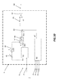
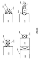
- Figure 15 shows different groupings for different kind of combustors.
- figure 15a shows a burner grouping A/B for an annular combustor
- figure 15b shows a fuel staging grouping A/B for a can combustor
- figure 15c shows a can grouping A/B for a can combustor.
- figure 16 shows examples of staging options.
- fuel injection stages are referenced with numerals 100 and 200, associated to a burner 2221 and the combustion chamber 222 of the combustor 22.
Landscapes
- Engineering & Computer Science (AREA)
- Chemical & Material Sciences (AREA)
- Combustion & Propulsion (AREA)
- Mechanical Engineering (AREA)
- General Engineering & Computer Science (AREA)
- Regulation And Control Of Combustion (AREA)
Abstract
Description
- The present invention generally relates to the field of combustion technology related to gas turbines. More in particular, the present invention refers to a method and system for operating a combustion device.
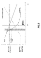
- As well known, emission regulations require low pollutant emission levels, which in the current state-of-the-art can be usually reached in gaseous fuel operation without any water addition thanks to premix combustion technologies. In liquid fuel operation, however, for most of the gas turbines addition of NOx water is mandatory to prevent pulsations, high NOx emissions and burner/combustor overheating. The ratio between the quantity of water introduced and the fuel is generally referred to as parameter ω (NOx water to fuel oil mass flow ratio). An example of how different combustor characteristics may react to varying proportion of NOx water or ω for a given operation point is shown in
Figure 1 , where also possible operational limitations due to emission regulation or lifetime impact due to combustor pulsation levels are indicated.Figure 2 shows the diagram offigure 1 where an optimum value ω* is indicated which should be kept during the combustion process to avoid high pulsations, to remain below NOx limit regulations and, at the same time, contain within acceptable ranges the water consumption. - Gas turbine combustor operation needs to be optimized for pulsation and emissions over a wide operating range. Typically, NOx water mass flow is scheduled as a function of gas turbine process variables, such as, for example, VIGV position and turbine exhaust temperature. These functions are pre-defined during engine adjustment based on combustor mapping results at a few points and boundary conditions under steady state. Typically, the combustor behaviour is heavily affected by ambient conditions, fuel property and hardware conditions, etc. The pre-defined NOx water to fuel oil mass flow ratio (co) is optimal for a specific engine and under operation and boundary conditions at the time of adjustment, but the optimum might differ during continuous commercial operation.
- Disadvantages of current solutions are that high margins to pulsation and NOx limits need to be included in the parameters settings in order to cover the expected variations in operation, which results in higher NOx water consumption and therefore important operational costs. Also, if larger deviations than expected occur in the boundary conditions or combustion characteristics, undesired events might be experienced leading to emission non-compliance or protection actions due to pulsation and therefore causing reduced engine reliability. Additionally, on site adjustment of the ω schedule is time consuming and leads to an increased commissioning and outage duration. Automatic ω adjustment is proposed in
US6679060B2 ,EP1215382B1 based on measurement of at least one among pulsation, material temperature, and flame position. These can be used to optimize pulsation and overheating risks but may still lead to high NOx levels and NOx water consumption. - It is an object of the present invention to solve the aforementioned technical problem by providing a system for operating a combustion device as substantially defined according to
independent claim 1. - It is a further object of the present invention to provide method for operating a combustion device as substantially defined in
independent claim 9. - According to an aspect of the invention, this object is obtained by a system for controlling a combustion process of a gas turbine, the gas turbine comprising a combustor and a fuel feeding system configured to control parameter ω defined as a ratio between NOx water and fuel oil mass flows, wherein the system comprises an apparatus for measuring NOx emission levels in the exhaust of the combustor; a measurement arrangement for measuring combustion process variables; a controller configured to receive input signals corresponding to measured NOx and process variables respectively from the apparatus and the measurement arrangement, to elaborate a value for the parameter ω based on the input signals and to generate and send an output signal correspondent to the calculated value directed to the fuel feeding system.
- According to a preferred aspect of the invention, the apparatus for measuring NOx emission levels is capable to carry out such operation within a time frame which is shorter than 20 sec.
- More preferably, the apparatus for measuring NOx emission levels is capable to carry out such operation within a time frame which is shorter than 10 sec.
- More preferably, the apparatus for measuring NOx emission levels is capable to carry out such operation within a time frame which is shorter than 2 sec.
- Even more preferably, the apparatus for measuring NOx emission levels is capable to carry out such operation within a time frame which is shorter than 1 sec.
- According to a preferred aspect of the invention, the measuring arrangement may comprise a device configured to measure pulsation levels within the combustor.
- According to a preferred aspect of the invention, the apparatus for measuring NOx emission levels may comprise an optical sensor device providing an array of nano and/or microcrystalline fibers.
- According to a preferred aspect of the invention, the system may comprise a fluid sample extraction assembly located in a combustor plenum, wherein the apparatus for measuring NOx emission levels is located at ambient conditions and is fluidically connected to the fluid sample extraction assembly.
- According to a preferred aspect of the invention, the apparatus for measuring NOx emission levels comprises a sensor located inside a combustor plenum and an evaluation unit connected thereto in turn located at ambient conditions.
- According to a preferred aspect of the invention, the controller may comprise first means for calculating a Δω based on measured levels of NOx emissions and pulsation levels.
- According to a preferred aspect of the invention, the controller may comprise second means for calculating a parameter ω' as a predefined function of measured process variables.
- According to a preferred aspect of the invention, the controller may comprise a subtracting device configured to receive input signals corresponding to the value of ω' calculated by the second means and to the value of Δω calculated by the first means, and to generate and send to the fuel feeding system an output signal corresponding to a value: co = ω' - Δω.
- According to a further object of the invention, it is provided a method for controlling a combustion process of a gas turbine, the gas turbine comprising at least a combustor and a fuel feeding system configured to control parameter co defined as a ratio between NOx water mass and fuel oil flows, said method including the steps of: measuring NOx emission levels in the exhaust of the combustor; measuring combustion process variables; elaborating a value for parameter co based on the NOx emissions and measured process variables and generating an output signal correspondent to the value co directed to the fuel feeding system.
- According to a preferred aspect of the invention, measuring NOx emission levels is carried out within a time frame which is shorter than 20 sec.
- More preferably, the NOx measures are carried out within a time frame which is shorter than 10 sec.
- More preferably, the NOx measures are carried out within a time frame which is shorter than 2 sec.
- Even more preferably, the NOx measures are carried out within a time frame which is shorter than 1 sec.
- According to a preferred aspect of the invention, the measuring combustion process variables may include measuring pulsation levels within the combustor.
- According to a preferred aspect of the invention, the step of elaborating a value for said parameter ω may comprise calculating a parameter ω' as a predefined function of measured process variables.
- According to a preferred aspect of the invention, the step of elaborating a value for said parameter ω may comprise a step of calculating a Δω based on measured levels of NOx emissions and pulsations.
- According to a preferred aspect of the invention, the step of elaborating a value for said parameter ω may comprise a step of subtracting the Δω from ω' and generating and sending to the fuel feeding system an output signal corresponding to a value ω = ω' - Δω.
- The objects, advantages and other features of the present invention will become more apparent upon reading of the following non-restrictive description of preferred embodiments thereof, given for the purpose of exemplification only, with reference to the accompany drawing, through which similar reference numerals may be used to refer to similar elements, and in which:
-
Figure 1 and2 show an operational diagram indicating various correlations between the ω of the process and other process variables; -
Figure 3 shows a simplified diagram of a system for controlling a combustion process according to the present invention; -
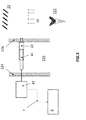
Figure 4 show a first example of a disposition of an apparatus for measuring NOx emission levels; -
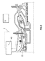
Figures 5 and6 show a second example of disposition of an apparatus for measuring NOx emission levels; -
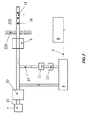
Figure 7 shows a third example of disposition of an apparatus for measuring NOx emission levels; -
Figure 8 and9 show a fourth example of disposition of an apparatus for measuring NOx emission levels; -
Figure 10 illustrates a block diagram of a first embodiment of a control logic according to a method of the present invention; -
Figure 11 shows in more detail a portion of the diagram offigure 10 ; -
Figure 12 illustrates a block diagram of a second embodiment of a control logic according to a method of the present invention; -
Figures 13 and14 show diagrams illustrating the variance of parameter ω according to predefined correlations -
Figure 15 and16 show respectively different groupings for different kind of combustors and examples of staging options. - Exemplary preferred embodiments of the invention will be now described with reference to the aforementioned drawings.
- With reference to
figure 3 , it is shown a simplified diagram of asystem 1 for controlling a combustion process according to the present invention. More in particular,system 1 is associated to agas turbine 2, which in turn comprises acompressor section 21, acombustor 22 and aturbine section 23.System 1 is also associated to a fuel feeding system, generally referred to withnumeral reference 3 in the scheme offigure 3 . Thefuel feeding system 3 comprises afirst means 31 to feed fuel into thecombustor 22 and asecond means 32 to control parameter co, therefore enabling the addition of water to the fuel. - The
system 1 comprises anapparatus 4 adapted to measure NOx emission levels produced in thecombustor 22 and/or in anexhaust 221 of thecombustor 22, and ameasurement arrangement arrangement 51 is adapted to measure process variables such as, for example, TAT (Temperature after Turbine), VIGV (Variable inlet guide vane angle), LHV (Low heating Value) and β (Fuel Gas mass flow to total fuel mass flow ratio), the latter being define by the following equation:
-
Arrangement 51 is configured to measure the current value of parameter ω, by calculating the flows of fuel and water. -
Arrangement 52 is configured to measure pulsation levels within the combustor. - The
system 1 according to the invention comprises acontroller 6, such as a data processor, configured to receiveinput signals 7 corresponding to the measured NOx levels and to other process variables, respectively fromapparatus 4 and from measuringarrangements fuel feeding system 3, which in turn regulates parameter ω of the process, in other words the ratio of water of the fuel-water emulsion introduced in the combustor. - A fuel feeding system is a configuration well-known in the art and therefore a detailed description of the same will be herewith omitted.
- Advantageously,
apparatus 4 for measuring the NOx levels is capable of measuring NOx emissions within a timeframe shorter than twenty seconds. - According to preferred embodiments, such NOx level measurements may be carried out within a time frame shorter than ten seconds. According to preferred embodiments, such NOx level measurements may be carried out within a time frame shorter than two seconds.
- According to preferred embodiments, such NOx level measurements may be carried out within a time frame shorter than one second.
- In this way, required measurements may be effected fast enough to ensure an optimum control of ω based not only on process variables but, most importantly, on NOx levels.
- In particular, a typical time interval (cycle time) for a gas turbine closed loop control is fifty msec. Hence, parameter ω is elaborated every fifty msec.
-
Apparatus 4 for measuring NOx levels may utilize technologies based on molecular-level measurements using stimulated Raman scattering. - As a preferred and non-limiting example,
apparatus 4 may include an optical sensor device for local analysis of a combustion process of a thermal power plant, which includes at least one wavelength selective optical element exposed directly or indirectly to hot combustion gases. More in particular, the optical element an array of nano and/or microcrystalline fibres which are created by shear flow crystallization. - Such device is known in the art and described in
US 2007/0133921 . By means of such optical device, local gas diagnostics, particularly for NOx pollutant emission levels, can be achieved within time frame shorter than 20 seconds. - According to preferred embodiments, optical device described in
US 2007/0133921 may be adapted to achieve such NOx emission levels within a time frame shorter than ten seconds. - According to preferred embodiments, optical device described in
US 2007/0133921 may be adapted to achieve such NOx emission levels within a time frame shorter than two seconds. - According to preferred embodiments, optical device described in
US 2007/0133921 may be adapted to achieve such NOx emission levels within a time frame shorter than one second. - With reference to next
figure 4 , it is shown a possible configuration of the system for controlling a combustion process according to the invention. In particular,apparatus 4 for measuring NOx emissions is located at ambient conditions (ca 20 C and 101.3 kPa) andexhaust gases 16 in a combustor plenum 225 (ca 700 K and 2 Mpa), surrounded by agas turbine casing 224, are extracted by means of a fluidsample extraction assembly 13 located inside thecombustor plenum 225 and fluidically connected to theapparatus 4. Theexhaust gases 16 are led through acooler 9 and apressure reduction valve 10. Then the gas to be analysed is directed to theapparatus 4 through abypass duct 14 which comprises one ormore filters 11 and, preferably, a drier 12. Theapparatus 4 performs the measurements, calculates the value of NOx levels and sends thecorrespondent output signal 7 to thecontroller 6. The exhaust gas going through theapparatus 4 is then expelled by means of avent 15. Advantageously, the bypass flow of exhaust gases through thebypass duct 14 allows a reduction of the measurement time. - Making now reference to following
figures 5 and6 , it is depicted another example of a possible configuration for the system for controlling a combustion process according to the invention. In this case, the apparatus for measuring NOx levels comprises asensor 41 located inside thecombustor plenum 225 delimited by thegas turbine casing 224 and acombustion liner 226. Thesensor 41 senseshot gases 18 coming from thecombustor chamber 222, where the temperature is around 1700 K and the pressure equal to 2 Mpa, through anupstream filter 19. The apparatus for measuring NOx levels further comprises anelectronic evaluation unit 42 which sends theoutput signal 7, corresponding to the NOx current value, to thecontroller 6. - With reference to
figure 7 , it is shown yet another example ofapparatus 4 located at ambient conditions. The configuration shown is similar to the one depicted infigure 5 with the sole difference that the pressure reduction valve is absent and it is replaced by anextraction pump 30, positioned downstream theapparatus 4, configured to withdrawhot gas samples 16 located in thecombustor plenum 225 through thesample extraction assembly 13. - Alternatively, as shown in
figures 8 and9 , thesensor 41 may be located within a gasturbine gas casing 50, where the temperature is around 600 C and the pressure equal to 101.3 kPa, and then connected to theelectronic evaluation unit 42 which is located at ambient conditions as described for the example illustrated infigure 6 . - The system for controlling the combustion process as described operating according to a method as described below.
- The method according to the invention includes the step of measuring NOx emission levels in the exhaust of the combustor; measuring combustion process variables; elaborating a value for parameter co based on the measured NOx emission levels and process variables; generating an output signal corresponding to the calculated co and sending it to the fuel feeding system.
- According to preferred embodiments the NOx measurement is accomplished within a time frame shorter than twenty seconds.
- According to preferred embodiments, the NOx measurement is accomplished within a time frame shorter than ten seconds.
- According to preferred embodiments, the NOx measurement is accomplished within a time frame shorter than two seconds. According to even more preferred embodiments, the NOx measurement is accomplished within a time frame shorter than one second.
- Making now reference to
figure 10 , it is shown a block diagram illustrating the method according to the invention. In particular, measured quantities, overall indicated withnumeral 7, include signals corresponding to the measuredNOx levels 72, thepulsation levels 71 and other process variables, likeTAT 73,VIGV 74 andβ 75 to quote some non-limiting examples. -
Signals 7 reach thecontroller unit 6 where they are elaborated in order to generate a value for parameter ω to be sent to the fuel feeding system. In particular,controller 6 comprises first means 61, which receives input signals 72 and 71 respectively corresponding to measured levels of NOx and pulsations, for calculating a Δω which represents a possible reduction of the value of ω, as it will be better explained in the following. -
Controller 6 further comprises second means 62, which receives as input signalsprocess variables measurements figure 13 graphs showing these typical functions are illustrated. They are defined based on combustor mapping results in order to keep enough margins from high pulsation and high NOx emission areas. Second means 62 utilize these functions, in a way known to those who are skilled in the art, to calculate ω'. - However, the combustor behaviour is heavily affected by ambient conditions, fuel property and hardware conditions. The pre-defined ω functions are optimal for an average engine and under average operative conditions, but usually result in too high NOx water consumption, with significant cost increase.
- First means 61 and second means 62 send, respectively, the reduction value Δω and the value co' to a subtracting
device 63 which generates and sends to the fuel feeding system an output signal corresponding to a value
- Generated ω value and signal 81 corresponding to the fuel oil mass flow command are sent to a
multiplier 64 which generates the NOx watermass flow command 82 which is sent to the fuel feeding system. - According to preferred embodiments, signal 71 corresponding to measured pulsation levels is sent, upstream the first means 61, to a subtracting
device 65. The subtractingdevice 65 subtracts the measured pulsation value from a predefined pulsation limit value and the result is fed to athreshold block 66 with hysteresis. Thethreshold block 66 is in turn connected to aswitch 67. It switches between two inputs: 0 or Δω coming fromfirst means 61, as detailed above. If the measured pulsation is below the pulsation limit, then Δω will be selected and passed to agradient limiter 68 and subsequently to subtractingdevice 63. Otherwise, if pulsation limit has been reached or passed, 0 will be selected and no reduction Δω will be enabled. - First means 61 is better detailed with reference to next
figure 11 , which will be now discussed. In particular, measuredpulsation 71 is fed to asubtracting device 611 which calculates the difference between the predefined pulsation limit and the measuredpulsation 71.Device 611 then feeds the result to afunction block 612, which is shown in a better detail in the bottom-right corner of the figure.Function block 612 has the purpose of calculating a necessary reduction from a predefined NOx emission level limit in order to keep the combustion away from high pulsation area. In the graph ofblock 612, x represents the input fed by the subtractingdevice 611, that is the difference between the pulsation limit and the measuredpulsation 71. The output f(x), identified in the scheme withnumeral 711, indicates the necessary reduction of NOx from the NOx limit calculated as a function of x. Subsequently, block 613 calculates aNOx target value 712 by subtracting the calculated reduction ofNOx 711 from the NOx limit value. First means 61 further comprises aPI controller 614 which receives as input the difference betweenNOx target value 712 and NOx measured value 72 (calculated by a subtracting device 615) and generates as output a possible reduction Δω based on the current NOx measuredvalue 72. - In order to prevent over firing and keep NOx water system running, a minimum NOx water mass flow is needed.
Block 616 is a divider which calculates a minimum ω to be ensured. - An alternative embodiment for the
controller 6 is represented in nextfigure 12 . It differs from the embodiment shown infigure 11 in the fact that a function generator block 61' is used which generates a possible reduction Δω. Particularly, the block 61' can reduce ω based on the measured NOx level emission.Figure 14 shows a typical example, including various ω curves for corresponding NOx emission measured levels. - It will be appreciated that for combustion processes having several fuel stages, the system according to the invention advantageously controls parameter ω to each fuel stage, in order to minimize NOx emissions, pulsations and overall water consumption.
- Moreover, for combustion processes with multiple burners or combustors/cans, a plurality of measurement systems as the one described may be utilized also to detect faulty can or combustor sectors.
- For combustion processes with multiple burners or combustors/cans and multiple fuel and multiple fuel and/or NOx water control, a plurality of measurement systems as the one described may be used to adjust multiple mass flows in order to minimize emissions, pulsation, and overall water consumption.
- It will be also appreciated that the system and the method according to the present invention may be applied to silo combustors, annular combustors, can combustors, sequential combustors, staged combustors, and to any combinations thereof, with separate fuel groups or stages.
-
Figure 15 shows different groupings for different kind of combustors. In particular,figure 15a shows a burner grouping A/B for an annular combustor;figure 15b shows a fuel staging grouping A/B for a can combustor;figure 15c shows a can grouping A/B for a can combustor. - Lastly,
figure 16 shows examples of staging options. In particular, fuel injection stages are referenced withnumerals burner 2221 and thecombustion chamber 222 of thecombustor 22. - While the invention has been described in detail in connection with only a limited number of embodiments, it should be readily understood that the invention is not limited to such disclosed embodiments. Rather, the invention can be modified to incorporate any number of variations, alterations, substitutions or equivalent arrangements not heretofore described, but which are commensurate with the spirit and scope of the invention.
- Additionally, while various embodiments of the invention have been described, it is to be understood that aspects of the invention may include only some of the described embodiments. Accordingly, the invention is not to be seen as limited by the foregoing description, but is only limited by the scope of the appended claims.
Claims (15)
- A system (1) for controlling a combustion process of a gas turbine (2), the gas turbine comprising a combustor (22) and a fuel feeding (3) system configured to control a parameter co defined as a ratio between NOx water and fuel oil mass flows, said system (1) comprising:- an apparatus (4) for measuring NOx emission levels in the exhaust of the combustor (22);- a measurement arrangement (51, 52) for measuring combustion process variables;- a controller (6) configured to receive input signals corresponding to measured NOx and process variables respectively from said apparatus (4) and from said measurement arrangement (51, 52);the system (1) being characterised in that said controller is configured to elaborate a value for the parameter co based on said input signals and to generate and send an output signal correspondent to said value directed to the fuel feeding system (3).
- The system (1) according to the preceding claim, wherein said apparatus (4) is capable of measuring NOx emissions within a time frame shorter than 20 sec.
- The system (1) according to claims 1 or 2, wherein said measuring arrangement (51, 52) comprises a device (52) configured to measure pulsation levels within the combustor (22).
- The system (1) according to any of claims 1-3, wherein said apparatus (4) for measuring NOx emission levels comprises an optical sensor device providing an array of nano and/or microcrystalline fibers.
- The system (1) according to any of the preceding claims, further comprising a fluid sample extraction assembly (13) located in a combustor plenum (225), wherein said apparatus (4) for measuring NOx emission levels is located at ambient conditions and is fluidically connected to said fluid sample extraction assembly (13).
- The system (1) according to any of claims 1 - 4, wherein said apparatus (4) for measuring NOx emission levels comprises a sensor (41) located inside a combustor plenum (225) and an evaluation unit (42) connected thereto in turn located at ambient conditions.
- The system (1) according to any of claims 3-6, wherein said controller (6) comprises first means (61) for calculating a parameter Δω based on measured levels of NOx (72) emissions and pulsations (71).
- The system (1) according to any of claims 3-7, wherein said controller (6) comprises second means (62) for calculating a parameter ω' as a predefined function of measured process variables.
- The system (1) according to claims 7 and 8, wherein said controller comprises a subtracting device (63) configured to receive input signals corresponding to said ω' calculated by said second means (62) and to said Δω' calculated by said first means (61), and to generate and send to the fuel feeding system (3) an output signal corresponding to a value:

- A method for controlling a combustion process of a gas turbine (2), the gas turbine comprising at least a combustor (22) and a fuel feeding system (3) configured to control parameter co defined as a ratio between NOx water mass and fuel oil flows, said method including the steps of:- measuring NOx emission levels in the exhaust of the combustor (22);- measuring combustion process variables;the method being characterised in that it comprises a step of elaborating a value for said parameter co based on said NOx emissions and measured process variables and generating an output signal correspondent to said value co directed to the fuel feeding system (3).
- The method according to the preceding claim, wherein each NOx emission measurement is accomplished within a time frame shorter than 20 sec.
- The method according to claims 10 or 11, wherein said measuring combustion process variables includes measuring pulsation levels within the combustor.
- The method according to any of claims 10-12, wherein said step of elaborating a value for said parameter co comprises calculating a parameter co' as a predefined function of measured process variables.
- The method according to claims 12 or 13, wherein said step of elaborating a value for said parameter co comprises a step of calculating a value Δω based on measured levels of NOx emissions and pulsations.
- The method according to claims 13 and 14, wherein said step of elaborating a value for said parameter ω comprises a step of subtracting said Δω from said ω' and generating and sending to the fuel feeding system (3) an output signal corresponding to a value: ω = co' - Δω.
Priority Applications (3)
| Application Number | Priority Date | Filing Date | Title |
|---|---|---|---|
| EP15170225.5A EP3101342B1 (en) | 2015-06-02 | 2015-06-02 | Method and system for operating a combustion device |
| US15/170,258 US20160356495A1 (en) | 2015-06-02 | 2016-06-01 | Method and system for operating a combustion device |
| CN201610384546.0A CN106224101B (en) | 2015-06-02 | 2016-06-02 | Method and system for operating a combustion device |
Applications Claiming Priority (1)
| Application Number | Priority Date | Filing Date | Title |
|---|---|---|---|
| EP15170225.5A EP3101342B1 (en) | 2015-06-02 | 2015-06-02 | Method and system for operating a combustion device |
Publications (2)
| Publication Number | Publication Date |
|---|---|
| EP3101342A1 true EP3101342A1 (en) | 2016-12-07 |
| EP3101342B1 EP3101342B1 (en) | 2020-04-29 |
Family
ID=53298199
Family Applications (1)
| Application Number | Title | Priority Date | Filing Date |
|---|---|---|---|
| EP15170225.5A Active EP3101342B1 (en) | 2015-06-02 | 2015-06-02 | Method and system for operating a combustion device |
Country Status (3)
| Country | Link |
|---|---|
| US (1) | US20160356495A1 (en) |
| EP (1) | EP3101342B1 (en) |
| CN (1) | CN106224101B (en) |
Cited By (2)
| Publication number | Priority date | Publication date | Assignee | Title |
|---|---|---|---|---|
| US11156164B2 (en) | 2019-05-21 | 2021-10-26 | General Electric Company | System and method for high frequency accoustic dampers with caps |
| US11174792B2 (en) | 2019-05-21 | 2021-11-16 | General Electric Company | System and method for high frequency acoustic dampers with baffles |
Families Citing this family (3)
| Publication number | Priority date | Publication date | Assignee | Title |
|---|---|---|---|---|
| US10436123B2 (en) | 2017-03-08 | 2019-10-08 | General Electric Company | Methods and apparatus for closed-loop control of a gas turbine |
| US11598225B2 (en) * | 2020-06-02 | 2023-03-07 | General Electric Company | System and method for reducing the visibility of exhaust emissions in a gas turbine system |
| US12221926B2 (en) * | 2022-06-08 | 2025-02-11 | General Electric Company | Multi-temperature fuel injectors for a gas turbine engine |
Citations (7)
| Publication number | Priority date | Publication date | Assignee | Title |
|---|---|---|---|---|
| GB2132112A (en) * | 1982-12-27 | 1984-07-04 | Gen Electric | Catalytic pollution control system for gas turbine exhaust |
| US6679060B2 (en) | 2000-12-16 | 2004-01-20 | Alstom Technology Ltd | Method for operating a premix burner |
| WO2004010052A1 (en) * | 2002-07-19 | 2004-01-29 | Alstom Technology Ltd | Method for controlling the introduction of inert media into a combustion chamber |
| US20070133921A1 (en) | 2005-12-08 | 2007-06-14 | Haffner Ken Y | Optical Sensor Device for Local Analysis of a Combustion Process in a Combustor of a Thermal Power Plant |
| CN201963380U (en) * | 2011-01-11 | 2011-09-07 | 无锡市凯龙汽车设备制造有限公司 | Diesel engine tail gas treatment system based on NOx (nitrogen oxide) sensor |
| EP2613034A1 (en) * | 2012-01-09 | 2013-07-10 | Alstom Technology Ltd | Method for operating a gas turbine |
| CN103884740A (en) * | 2012-12-20 | 2014-06-25 | 中国科学院上海硅酸盐研究所 | Zirconia-based NOx sensor and preparation method thereof |
Family Cites Families (2)
| Publication number | Priority date | Publication date | Assignee | Title |
|---|---|---|---|---|
| EP2837888A1 (en) * | 2013-08-15 | 2015-02-18 | Alstom Technology Ltd | Sequential combustion with dilution gas mixer |
| EP2857658A1 (en) * | 2013-10-01 | 2015-04-08 | Alstom Technology Ltd | Gas turbine with sequential combustion arrangement |
-
2015
- 2015-06-02 EP EP15170225.5A patent/EP3101342B1/en active Active
-
2016
- 2016-06-01 US US15/170,258 patent/US20160356495A1/en not_active Abandoned
- 2016-06-02 CN CN201610384546.0A patent/CN106224101B/en active Active
Patent Citations (8)
| Publication number | Priority date | Publication date | Assignee | Title |
|---|---|---|---|---|
| GB2132112A (en) * | 1982-12-27 | 1984-07-04 | Gen Electric | Catalytic pollution control system for gas turbine exhaust |
| US6679060B2 (en) | 2000-12-16 | 2004-01-20 | Alstom Technology Ltd | Method for operating a premix burner |
| EP1215382B1 (en) | 2000-12-16 | 2007-08-22 | ALSTOM Technology Ltd | Method of operating a premix burner |
| WO2004010052A1 (en) * | 2002-07-19 | 2004-01-29 | Alstom Technology Ltd | Method for controlling the introduction of inert media into a combustion chamber |
| US20070133921A1 (en) | 2005-12-08 | 2007-06-14 | Haffner Ken Y | Optical Sensor Device for Local Analysis of a Combustion Process in a Combustor of a Thermal Power Plant |
| CN201963380U (en) * | 2011-01-11 | 2011-09-07 | 无锡市凯龙汽车设备制造有限公司 | Diesel engine tail gas treatment system based on NOx (nitrogen oxide) sensor |
| EP2613034A1 (en) * | 2012-01-09 | 2013-07-10 | Alstom Technology Ltd | Method for operating a gas turbine |
| CN103884740A (en) * | 2012-12-20 | 2014-06-25 | 中国科学院上海硅酸盐研究所 | Zirconia-based NOx sensor and preparation method thereof |
Cited By (2)
| Publication number | Priority date | Publication date | Assignee | Title |
|---|---|---|---|---|
| US11156164B2 (en) | 2019-05-21 | 2021-10-26 | General Electric Company | System and method for high frequency accoustic dampers with caps |
| US11174792B2 (en) | 2019-05-21 | 2021-11-16 | General Electric Company | System and method for high frequency acoustic dampers with baffles |
Also Published As
| Publication number | Publication date |
|---|---|
| CN106224101B (en) | 2020-11-20 |
| US20160356495A1 (en) | 2016-12-08 |
| EP3101342B1 (en) | 2020-04-29 |
| CN106224101A (en) | 2016-12-14 |
Similar Documents
| Publication | Publication Date | Title |
|---|---|---|
| CN1971013B (en) | Methods and apparatus for operating gas turbine engine systems | |
| EP3101342B1 (en) | Method and system for operating a combustion device | |
| EP2031192B1 (en) | Method and system for detection of gas turbine combustion blowouts utilizing fuel normalized power response | |
| CA2608042C (en) | Method and device for regulating the operating line of a gas turbine combustion chamber | |
| EP2570877A1 (en) | System and method for simulating gas turbine operation | |
| EP2562612B1 (en) | Methods and systems for gas turbine modeling using adaptive kalman filter | |
| EP3069083B1 (en) | Intelligent control method with predictive emissions monitoring ability | |
| EP2486328B1 (en) | Combustion apparatus | |
| EP3521593B1 (en) | Gas turbine combustor, gas turbine, and control method for gas turbine combustor | |
| EP2570616A2 (en) | System and method for simulating a gas turbine compressor | |
| EP1387062A2 (en) | Method/system for mapping a combustor in a gas turbine engine | |
| EP2423489A2 (en) | Methods for controlling fuel splits to a gas turbine combustor | |
| EP2442031A1 (en) | Combustion device with pulsed fuel split | |
| EP1114279A1 (en) | Dynamic control system and method for catalytic combustion process and gas turbine engine utilizing same | |
| EP3239614A1 (en) | Systems and methods of predicting physical parameters for a combustion fuel system | |
| US20140182297A1 (en) | Gas turbine and method of controlling a gas turbine at part-load condition | |
| EP3061945B1 (en) | Method for controlling the operation of a gas turbine with sequential combustion | |
| EP3421761B1 (en) | Second-stage combustor for a sequential combustor of a gas turbine | |
| US20150075170A1 (en) | Method and system for augmenting the detection reliability of secondary flame detectors in a gas turbine | |
| US12523377B2 (en) | Gas turbine control device, gas turbine control method, and storage medium |
Legal Events
| Date | Code | Title | Description |
|---|---|---|---|
| PUAI | Public reference made under article 153(3) epc to a published international application that has entered the european phase |
Free format text: ORIGINAL CODE: 0009012 |
|
| STAA | Information on the status of an ep patent application or granted ep patent |
Free format text: STATUS: THE APPLICATION HAS BEEN PUBLISHED |
|
| AK | Designated contracting states |
Kind code of ref document: A1 Designated state(s): AL AT BE BG CH CY CZ DE DK EE ES FI FR GB GR HR HU IE IS IT LI LT LU LV MC MK MT NL NO PL PT RO RS SE SI SK SM TR |
|
| AX | Request for extension of the european patent |
Extension state: BA ME |
|
| RAP1 | Party data changed (applicant data changed or rights of an application transferred) |
Owner name: ANSALDO ENERGIA IP UK LIMITED |
|
| STAA | Information on the status of an ep patent application or granted ep patent |
Free format text: STATUS: REQUEST FOR EXAMINATION WAS MADE |
|
| 17P | Request for examination filed |
Effective date: 20170606 |
|
| RBV | Designated contracting states (corrected) |
Designated state(s): AL AT BE BG CH CY CZ DE DK EE ES FI FR GB GR HR HU IE IS IT LI LT LU LV MC MK MT NL NO PL PT RO RS SE SI SK SM TR |
|
| STAA | Information on the status of an ep patent application or granted ep patent |
Free format text: STATUS: EXAMINATION IS IN PROGRESS |
|
| 17Q | First examination report despatched |
Effective date: 20190103 |
|
| GRAP | Despatch of communication of intention to grant a patent |
Free format text: ORIGINAL CODE: EPIDOSNIGR1 |
|
| STAA | Information on the status of an ep patent application or granted ep patent |
Free format text: STATUS: GRANT OF PATENT IS INTENDED |
|
| INTG | Intention to grant announced |
Effective date: 20191126 |
|
| GRAS | Grant fee paid |
Free format text: ORIGINAL CODE: EPIDOSNIGR3 |
|
| GRAA | (expected) grant |
Free format text: ORIGINAL CODE: 0009210 |
|
| STAA | Information on the status of an ep patent application or granted ep patent |
Free format text: STATUS: THE PATENT HAS BEEN GRANTED |
|
| AK | Designated contracting states |
Kind code of ref document: B1 Designated state(s): AL AT BE BG CH CY CZ DE DK EE ES FI FR GB GR HR HU IE IS IT LI LT LU LV MC MK MT NL NO PL PT RO RS SE SI SK SM TR |
|
| REG | Reference to a national code |
Ref country code: GB Ref legal event code: FG4D |
|
| REG | Reference to a national code |
Ref country code: CH Ref legal event code: EP |
|
| REG | Reference to a national code |
Ref country code: AT Ref legal event code: REF Ref document number: 1263886 Country of ref document: AT Kind code of ref document: T Effective date: 20200515 |
|
| REG | Reference to a national code |
Ref country code: DE Ref legal event code: R096 Ref document number: 602015051500 Country of ref document: DE |
|
| REG | Reference to a national code |
Ref country code: IE Ref legal event code: FG4D |
|
| REG | Reference to a national code |
Ref country code: NL Ref legal event code: MP Effective date: 20200429 |
|
| REG | Reference to a national code |
Ref country code: LT Ref legal event code: MG4D |
|
| PG25 | Lapsed in a contracting state [announced via postgrant information from national office to epo] |
Ref country code: NO Free format text: LAPSE BECAUSE OF FAILURE TO SUBMIT A TRANSLATION OF THE DESCRIPTION OR TO PAY THE FEE WITHIN THE PRESCRIBED TIME-LIMIT Effective date: 20200729 Ref country code: FI Free format text: LAPSE BECAUSE OF FAILURE TO SUBMIT A TRANSLATION OF THE DESCRIPTION OR TO PAY THE FEE WITHIN THE PRESCRIBED TIME-LIMIT Effective date: 20200429 Ref country code: PT Free format text: LAPSE BECAUSE OF FAILURE TO SUBMIT A TRANSLATION OF THE DESCRIPTION OR TO PAY THE FEE WITHIN THE PRESCRIBED TIME-LIMIT Effective date: 20200831 Ref country code: SE Free format text: LAPSE BECAUSE OF FAILURE TO SUBMIT A TRANSLATION OF THE DESCRIPTION OR TO PAY THE FEE WITHIN THE PRESCRIBED TIME-LIMIT Effective date: 20200429 Ref country code: IS Free format text: LAPSE BECAUSE OF FAILURE TO SUBMIT A TRANSLATION OF THE DESCRIPTION OR TO PAY THE FEE WITHIN THE PRESCRIBED TIME-LIMIT Effective date: 20200829 Ref country code: GR Free format text: LAPSE BECAUSE OF FAILURE TO SUBMIT A TRANSLATION OF THE DESCRIPTION OR TO PAY THE FEE WITHIN THE PRESCRIBED TIME-LIMIT Effective date: 20200730 Ref country code: LT Free format text: LAPSE BECAUSE OF FAILURE TO SUBMIT A TRANSLATION OF THE DESCRIPTION OR TO PAY THE FEE WITHIN THE PRESCRIBED TIME-LIMIT Effective date: 20200429 |
|
| REG | Reference to a national code |
Ref country code: AT Ref legal event code: MK05 Ref document number: 1263886 Country of ref document: AT Kind code of ref document: T Effective date: 20200429 |
|
| PG25 | Lapsed in a contracting state [announced via postgrant information from national office to epo] |
Ref country code: RS Free format text: LAPSE BECAUSE OF FAILURE TO SUBMIT A TRANSLATION OF THE DESCRIPTION OR TO PAY THE FEE WITHIN THE PRESCRIBED TIME-LIMIT Effective date: 20200429 Ref country code: HR Free format text: LAPSE BECAUSE OF FAILURE TO SUBMIT A TRANSLATION OF THE DESCRIPTION OR TO PAY THE FEE WITHIN THE PRESCRIBED TIME-LIMIT Effective date: 20200429 Ref country code: BG Free format text: LAPSE BECAUSE OF FAILURE TO SUBMIT A TRANSLATION OF THE DESCRIPTION OR TO PAY THE FEE WITHIN THE PRESCRIBED TIME-LIMIT Effective date: 20200729 Ref country code: LV Free format text: LAPSE BECAUSE OF FAILURE TO SUBMIT A TRANSLATION OF THE DESCRIPTION OR TO PAY THE FEE WITHIN THE PRESCRIBED TIME-LIMIT Effective date: 20200429 |
|
| PG25 | Lapsed in a contracting state [announced via postgrant information from national office to epo] |
Ref country code: NL Free format text: LAPSE BECAUSE OF FAILURE TO SUBMIT A TRANSLATION OF THE DESCRIPTION OR TO PAY THE FEE WITHIN THE PRESCRIBED TIME-LIMIT Effective date: 20200429 Ref country code: AL Free format text: LAPSE BECAUSE OF FAILURE TO SUBMIT A TRANSLATION OF THE DESCRIPTION OR TO PAY THE FEE WITHIN THE PRESCRIBED TIME-LIMIT Effective date: 20200429 |
|
| PG25 | Lapsed in a contracting state [announced via postgrant information from national office to epo] |
Ref country code: ES Free format text: LAPSE BECAUSE OF FAILURE TO SUBMIT A TRANSLATION OF THE DESCRIPTION OR TO PAY THE FEE WITHIN THE PRESCRIBED TIME-LIMIT Effective date: 20200429 Ref country code: MC Free format text: LAPSE BECAUSE OF FAILURE TO SUBMIT A TRANSLATION OF THE DESCRIPTION OR TO PAY THE FEE WITHIN THE PRESCRIBED TIME-LIMIT Effective date: 20200429 Ref country code: AT Free format text: LAPSE BECAUSE OF FAILURE TO SUBMIT A TRANSLATION OF THE DESCRIPTION OR TO PAY THE FEE WITHIN THE PRESCRIBED TIME-LIMIT Effective date: 20200429 Ref country code: DK Free format text: LAPSE BECAUSE OF FAILURE TO SUBMIT A TRANSLATION OF THE DESCRIPTION OR TO PAY THE FEE WITHIN THE PRESCRIBED TIME-LIMIT Effective date: 20200429 Ref country code: EE Free format text: LAPSE BECAUSE OF FAILURE TO SUBMIT A TRANSLATION OF THE DESCRIPTION OR TO PAY THE FEE WITHIN THE PRESCRIBED TIME-LIMIT Effective date: 20200429 Ref country code: SM Free format text: LAPSE BECAUSE OF FAILURE TO SUBMIT A TRANSLATION OF THE DESCRIPTION OR TO PAY THE FEE WITHIN THE PRESCRIBED TIME-LIMIT Effective date: 20200429 Ref country code: IT Free format text: LAPSE BECAUSE OF FAILURE TO SUBMIT A TRANSLATION OF THE DESCRIPTION OR TO PAY THE FEE WITHIN THE PRESCRIBED TIME-LIMIT Effective date: 20200429 Ref country code: RO Free format text: LAPSE BECAUSE OF FAILURE TO SUBMIT A TRANSLATION OF THE DESCRIPTION OR TO PAY THE FEE WITHIN THE PRESCRIBED TIME-LIMIT Effective date: 20200429 Ref country code: CZ Free format text: LAPSE BECAUSE OF FAILURE TO SUBMIT A TRANSLATION OF THE DESCRIPTION OR TO PAY THE FEE WITHIN THE PRESCRIBED TIME-LIMIT Effective date: 20200429 |
|
| REG | Reference to a national code |
Ref country code: CH Ref legal event code: PL |
|
| REG | Reference to a national code |
Ref country code: DE Ref legal event code: R097 Ref document number: 602015051500 Country of ref document: DE |
|
| PG25 | Lapsed in a contracting state [announced via postgrant information from national office to epo] |
Ref country code: PL Free format text: LAPSE BECAUSE OF FAILURE TO SUBMIT A TRANSLATION OF THE DESCRIPTION OR TO PAY THE FEE WITHIN THE PRESCRIBED TIME-LIMIT Effective date: 20200429 Ref country code: SK Free format text: LAPSE BECAUSE OF FAILURE TO SUBMIT A TRANSLATION OF THE DESCRIPTION OR TO PAY THE FEE WITHIN THE PRESCRIBED TIME-LIMIT Effective date: 20200429 |
|
| PLBE | No opposition filed within time limit |
Free format text: ORIGINAL CODE: 0009261 |
|
| STAA | Information on the status of an ep patent application or granted ep patent |
Free format text: STATUS: NO OPPOSITION FILED WITHIN TIME LIMIT |
|
| GBPC | Gb: european patent ceased through non-payment of renewal fee |
Effective date: 20200729 |
|
| PG25 | Lapsed in a contracting state [announced via postgrant information from national office to epo] |
Ref country code: LU Free format text: LAPSE BECAUSE OF NON-PAYMENT OF DUE FEES Effective date: 20200602 |
|
| 26N | No opposition filed |
Effective date: 20210201 |
|
| REG | Reference to a national code |
Ref country code: BE Ref legal event code: MM Effective date: 20200630 |
|
| PG25 | Lapsed in a contracting state [announced via postgrant information from national office to epo] |
Ref country code: LI Free format text: LAPSE BECAUSE OF NON-PAYMENT OF DUE FEES Effective date: 20200630 Ref country code: FR Free format text: LAPSE BECAUSE OF NON-PAYMENT OF DUE FEES Effective date: 20200629 Ref country code: CH Free format text: LAPSE BECAUSE OF NON-PAYMENT OF DUE FEES Effective date: 20200630 Ref country code: GB Free format text: LAPSE BECAUSE OF NON-PAYMENT OF DUE FEES Effective date: 20200729 Ref country code: IE Free format text: LAPSE BECAUSE OF NON-PAYMENT OF DUE FEES Effective date: 20200602 |
|
| PG25 | Lapsed in a contracting state [announced via postgrant information from national office to epo] |
Ref country code: BE Free format text: LAPSE BECAUSE OF NON-PAYMENT OF DUE FEES Effective date: 20200630 Ref country code: SI Free format text: LAPSE BECAUSE OF FAILURE TO SUBMIT A TRANSLATION OF THE DESCRIPTION OR TO PAY THE FEE WITHIN THE PRESCRIBED TIME-LIMIT Effective date: 20200429 |
|
| PG25 | Lapsed in a contracting state [announced via postgrant information from national office to epo] |
Ref country code: TR Free format text: LAPSE BECAUSE OF FAILURE TO SUBMIT A TRANSLATION OF THE DESCRIPTION OR TO PAY THE FEE WITHIN THE PRESCRIBED TIME-LIMIT Effective date: 20200429 Ref country code: MT Free format text: LAPSE BECAUSE OF FAILURE TO SUBMIT A TRANSLATION OF THE DESCRIPTION OR TO PAY THE FEE WITHIN THE PRESCRIBED TIME-LIMIT Effective date: 20200429 Ref country code: CY Free format text: LAPSE BECAUSE OF FAILURE TO SUBMIT A TRANSLATION OF THE DESCRIPTION OR TO PAY THE FEE WITHIN THE PRESCRIBED TIME-LIMIT Effective date: 20200429 |
|
| PG25 | Lapsed in a contracting state [announced via postgrant information from national office to epo] |
Ref country code: MK Free format text: LAPSE BECAUSE OF FAILURE TO SUBMIT A TRANSLATION OF THE DESCRIPTION OR TO PAY THE FEE WITHIN THE PRESCRIBED TIME-LIMIT Effective date: 20200429 |
|
| P01 | Opt-out of the competence of the unified patent court (upc) registered |
Effective date: 20240430 |
|
| PGFP | Annual fee paid to national office [announced via postgrant information from national office to epo] |
Ref country code: DE Payment date: 20250618 Year of fee payment: 11 |