EP3101260A1 - Afterburner and aircraft engine - Google Patents
Afterburner and aircraft engine Download PDFInfo
- Publication number
- EP3101260A1 EP3101260A1 EP15786393.7A EP15786393A EP3101260A1 EP 3101260 A1 EP3101260 A1 EP 3101260A1 EP 15786393 A EP15786393 A EP 15786393A EP 3101260 A1 EP3101260 A1 EP 3101260A1
- Authority
- EP
- European Patent Office
- Prior art keywords
- liner
- flame
- aircraft engine
- circumferential surface
- afterburner
- Prior art date
- Legal status (The legal status is an assumption and is not a legal conclusion. Google has not performed a legal analysis and makes no representation as to the accuracy of the status listed.)
- Granted
Links
Images


Classifications
-
- F—MECHANICAL ENGINEERING; LIGHTING; HEATING; WEAPONS; BLASTING
- F23—COMBUSTION APPARATUS; COMBUSTION PROCESSES
- F23R—GENERATING COMBUSTION PRODUCTS OF HIGH PRESSURE OR HIGH VELOCITY, e.g. GAS-TURBINE COMBUSTION CHAMBERS
- F23R3/00—Continuous combustion chambers using liquid or gaseous fuel
- F23R3/02—Continuous combustion chambers using liquid or gaseous fuel characterised by the air-flow or gas-flow configuration
- F23R3/16—Continuous combustion chambers using liquid or gaseous fuel characterised by the air-flow or gas-flow configuration with devices inside the flame tube or the combustion chamber to influence the air or gas flow
- F23R3/18—Flame stabilising means, e.g. flame holders for after-burners of jet-propulsion plants
- F23R3/20—Flame stabilising means, e.g. flame holders for after-burners of jet-propulsion plants incorporating fuel injection means
-
- F—MECHANICAL ENGINEERING; LIGHTING; HEATING; WEAPONS; BLASTING
- F01—MACHINES OR ENGINES IN GENERAL; ENGINE PLANTS IN GENERAL; STEAM ENGINES
- F01D—NON-POSITIVE DISPLACEMENT MACHINES OR ENGINES, e.g. STEAM TURBINES
- F01D25/00—Component parts, details, or accessories, not provided for in, or of interest apart from, other groups
- F01D25/24—Casings; Casing parts, e.g. diaphragms, casing fastenings
-
- F—MECHANICAL ENGINEERING; LIGHTING; HEATING; WEAPONS; BLASTING
- F01—MACHINES OR ENGINES IN GENERAL; ENGINE PLANTS IN GENERAL; STEAM ENGINES
- F01D—NON-POSITIVE DISPLACEMENT MACHINES OR ENGINES, e.g. STEAM TURBINES
- F01D25/00—Component parts, details, or accessories, not provided for in, or of interest apart from, other groups
- F01D25/30—Exhaust heads, chambers, or the like
- F01D25/305—Exhaust heads, chambers, or the like with fluid, e.g. liquid injection
-
- F—MECHANICAL ENGINEERING; LIGHTING; HEATING; WEAPONS; BLASTING
- F02—COMBUSTION ENGINES; HOT-GAS OR COMBUSTION-PRODUCT ENGINE PLANTS
- F02K—JET-PROPULSION PLANTS
- F02K1/00—Plants characterised by the form or arrangement of the jet pipe or nozzle; Jet pipes or nozzles peculiar thereto
- F02K1/78—Other construction of jet pipes
- F02K1/82—Jet pipe walls, e.g. liners
- F02K1/822—Heat insulating structures or liners, cooling arrangements, e.g. post combustion liners; Infrared radiation suppressors
-
- F—MECHANICAL ENGINEERING; LIGHTING; HEATING; WEAPONS; BLASTING
- F02—COMBUSTION ENGINES; HOT-GAS OR COMBUSTION-PRODUCT ENGINE PLANTS
- F02K—JET-PROPULSION PLANTS
- F02K3/00—Plants including a gas turbine driving a compressor or a ducted fan
- F02K3/08—Plants including a gas turbine driving a compressor or a ducted fan with supplementary heating of the working fluid; Control thereof
- F02K3/10—Plants including a gas turbine driving a compressor or a ducted fan with supplementary heating of the working fluid; Control thereof by after-burners
-
- F—MECHANICAL ENGINEERING; LIGHTING; HEATING; WEAPONS; BLASTING
- F23—COMBUSTION APPARATUS; COMBUSTION PROCESSES
- F23R—GENERATING COMBUSTION PRODUCTS OF HIGH PRESSURE OR HIGH VELOCITY, e.g. GAS-TURBINE COMBUSTION CHAMBERS
- F23R3/00—Continuous combustion chambers using liquid or gaseous fuel
- F23R3/02—Continuous combustion chambers using liquid or gaseous fuel characterised by the air-flow or gas-flow configuration
- F23R3/16—Continuous combustion chambers using liquid or gaseous fuel characterised by the air-flow or gas-flow configuration with devices inside the flame tube or the combustion chamber to influence the air or gas flow
- F23R3/18—Flame stabilising means, e.g. flame holders for after-burners of jet-propulsion plants
-
- F—MECHANICAL ENGINEERING; LIGHTING; HEATING; WEAPONS; BLASTING
- F23—COMBUSTION APPARATUS; COMBUSTION PROCESSES
- F23R—GENERATING COMBUSTION PRODUCTS OF HIGH PRESSURE OR HIGH VELOCITY, e.g. GAS-TURBINE COMBUSTION CHAMBERS
- F23R3/00—Continuous combustion chambers using liquid or gaseous fuel
- F23R3/28—Continuous combustion chambers using liquid or gaseous fuel characterised by the fuel supply
-
- F—MECHANICAL ENGINEERING; LIGHTING; HEATING; WEAPONS; BLASTING
- F23—COMBUSTION APPARATUS; COMBUSTION PROCESSES
- F23R—GENERATING COMBUSTION PRODUCTS OF HIGH PRESSURE OR HIGH VELOCITY, e.g. GAS-TURBINE COMBUSTION CHAMBERS
- F23R3/00—Continuous combustion chambers using liquid or gaseous fuel
- F23R3/28—Continuous combustion chambers using liquid or gaseous fuel characterised by the fuel supply
- F23R3/286—Continuous combustion chambers using liquid or gaseous fuel characterised by the fuel supply having fuel-air premixing devices
-
- F—MECHANICAL ENGINEERING; LIGHTING; HEATING; WEAPONS; BLASTING
- F23—COMBUSTION APPARATUS; COMBUSTION PROCESSES
- F23R—GENERATING COMBUSTION PRODUCTS OF HIGH PRESSURE OR HIGH VELOCITY, e.g. GAS-TURBINE COMBUSTION CHAMBERS
- F23R3/00—Continuous combustion chambers using liquid or gaseous fuel
- F23R3/28—Continuous combustion chambers using liquid or gaseous fuel characterised by the fuel supply
- F23R3/34—Feeding into different combustion zones
-
- F—MECHANICAL ENGINEERING; LIGHTING; HEATING; WEAPONS; BLASTING
- F05—INDEXING SCHEMES RELATING TO ENGINES OR PUMPS IN VARIOUS SUBCLASSES OF CLASSES F01-F04
- F05D—INDEXING SCHEME FOR ASPECTS RELATING TO NON-POSITIVE-DISPLACEMENT MACHINES OR ENGINES, GAS-TURBINES OR JET-PROPULSION PLANTS
- F05D2220/00—Application
- F05D2220/30—Application in turbines
- F05D2220/32—Application in turbines in gas turbines
- F05D2220/323—Application in turbines in gas turbines for aircraft propulsion, e.g. jet engines
-
- F—MECHANICAL ENGINEERING; LIGHTING; HEATING; WEAPONS; BLASTING
- F05—INDEXING SCHEMES RELATING TO ENGINES OR PUMPS IN VARIOUS SUBCLASSES OF CLASSES F01-F04
- F05D—INDEXING SCHEME FOR ASPECTS RELATING TO NON-POSITIVE-DISPLACEMENT MACHINES OR ENGINES, GAS-TURBINES OR JET-PROPULSION PLANTS
- F05D2240/00—Components
- F05D2240/35—Combustors or associated equipment
-
- F—MECHANICAL ENGINEERING; LIGHTING; HEATING; WEAPONS; BLASTING
- F23—COMBUSTION APPARATUS; COMBUSTION PROCESSES
- F23R—GENERATING COMBUSTION PRODUCTS OF HIGH PRESSURE OR HIGH VELOCITY, e.g. GAS-TURBINE COMBUSTION CHAMBERS
- F23R2900/00—Special features of, or arrangements for continuous combustion chambers; Combustion processes therefor
- F23R2900/03041—Effusion cooled combustion chamber walls or domes
-
- Y—GENERAL TAGGING OF NEW TECHNOLOGICAL DEVELOPMENTS; GENERAL TAGGING OF CROSS-SECTIONAL TECHNOLOGIES SPANNING OVER SEVERAL SECTIONS OF THE IPC; TECHNICAL SUBJECTS COVERED BY FORMER USPC CROSS-REFERENCE ART COLLECTIONS [XRACs] AND DIGESTS
- Y02—TECHNOLOGIES OR APPLICATIONS FOR MITIGATION OR ADAPTATION AGAINST CLIMATE CHANGE
- Y02T—CLIMATE CHANGE MITIGATION TECHNOLOGIES RELATED TO TRANSPORTATION
- Y02T50/00—Aeronautics or air transport
- Y02T50/60—Efficient propulsion technologies, e.g. for aircraft
Definitions
- the throttle ring which throttles the main flow of the gas mixture is provided at the position aligned with the radial flame folding member on the inner circumferential surface of the liner. This increases the difference in pressure between the outside of the liner and the outlet of the throttle ring.
- the cooling air blown out of the cooling holes located in the frame holder side of the liner therefore forms a stable film cooling layer directly downstream of the flame holder on the inner circumferential surface of the liner. It is therefore possible to sufficiently increase the performance of cooling the part of the liner directly downstream of the flame holder without increasing the number of cooling holes located in part of the liner 31 on the flame holder side or in part upstream of the flame holder.
- an aircraft engine 1 is a device which discharges combustion gas (high-temperature gas) G and air (low-temperature air) A rearward to generate thrust (engine thrust).
- the aircraft engine 1 includes a cylindrical core case (an engine inner cylinder) 3, inside of which an annular core flow path (a main flow path) 5 is formed. Outside of the core case 3, a cylindrical engine case (an engine outer cylinder) 7 is situated concentrically with the core case 3. Between the inner circumferential surface of the engine case 7 and the outer circumferential surface of the core case 3, an annular fan flow path (a bypass flow path) 9 is formed.
- an afterburner 25 is situated in rear part of the engine case 7.
- the afterburner 25 supplies fuel to a gas mixture of the combustion gas G discharged from the core flow path 5 and the air (low-temperature air) A from the fan flow path 9 for burning (afterburning) to increase the thrust (engine thrust) of the aircraft engine 1.
- an exhaust nozzle 27 is situated behind the afterburner 25, an exhaust nozzle 27 is situated. The exhaust nozzle 27 discharges the combustion gas G and air A (the gas mixture of the combustion gas G and air A).
- a part of the air A discharged from the fan flow path 9 flows through the cooling flow path 35 as the cooling air CA during operation of the aircraft engine 1.
- the liner 31 is therefore convection-cooled.
- the cooling air CA having contributed to the convection cooling of the liner 31 is blown out from the plural cooling holes 37 and forms the film cooling layer (not illustrated) covering the inner circumferential surface of the liner 31.
- the liner 31 is therefore film-cooled.
- the cooling air CA having contributed to the film cooling of the liner 31 becomes a part of the gas mixture (normal operation of the afterburner 25).
Landscapes
- Engineering & Computer Science (AREA)
- Chemical & Material Sciences (AREA)
- Combustion & Propulsion (AREA)
- Mechanical Engineering (AREA)
- General Engineering & Computer Science (AREA)
- Cylinder Crankcases Of Internal Combustion Engines (AREA)
Abstract
Description
- The present embodiment relates to an afterburner or the like which supplies fuel to a gas mixture of combustion gas discharged from a core flow path of an aircraft engine and air discharged from a fan flow path of the aircraft engine for burning (afterburning) to increase thrust of the aircraft engine.
- Various studies and developments are being made on afterburners in recent years according to demand for increasing thrust of aircraft engines. The configuration of a general afterburner is briefly described below.
- At the outlet of (behind) an engine case of an aircraft engine, a rear duct (an exhaust duct) is provided. Within the rear duct, a cylindrical liner is provided, through which a gas mixture flows. Between the outer circumferential surface of the liner and the inner circumferential surface of the rear duct, an annular cooling flow path is formed, through which a part of air discharged from a fan flow path flows as cooling air. The liner is provided with plural penetrating cooling holes to blow out the cooling air along the inner circumferential surface of the liner. The cooling air flows through the cooling flow path during operation of the aircraft engine for convection cooling of the liner. The cooling air having contributed to the convection cooling of the liner blows out of the plural cooling holes to form a film cooling layer covering the inner circumferential surface of the liner for film cooling of the liner.
- The rear duct is provided with a fuel injector which injects fuel liquid in the liner. Downstream of the fuel injector in the rear duct, an igniter (an ignition plug) is provided. The igniter ignites the gas mixture containing the fuel in the liner. Downstream of the fuel injector in the liner, a flame holder to hold flame is also provided. The flame holder includes plural radial frame holding members which are situated in a radial fashion within the liner. Each radial flame holding member forms a flame holding area (low-velocity area).
- The conventional arts relating to the present embodiment are disclosed in
Patent Documents 1 and 2. -
- Patent Document 1:
JP 2008-8606 A - Patent Document 2:
JP H9-4511 A - Burnout of the liner during operation of the aircraft engine does not occur evenly across the liner. Burnout tends to be severe downstream of the flame holder in the liner. To increase the durability of the liner, that is, the durability of the afterburner, it may be suitable to increase the number of cooling holes located in a portion near the flame holder in the liner (a portion aligned with the flame holder) or in a portion upstream of the flame holder and thereby increase the performance of cooling the part of the liner directly downstream of the flame holder. On the other hand, increasing the number of cooling holes results in increasing the flow rate of consumed cooling air, thus reducing the engine efficiency of the aircraft engine. It is therefore difficult to increase the durability of the afterburner while preventing a decrease in engine efficiency of the aircraft engine.
- Accordingly, an object of the present embodiment is to provide an afterburner having a new configuration and the like which are capable of solving the aforementioned problem.
- A first aspect of the present embodiment is an afterburner which supplies fuel to a gas mixture of combustion gas discharged from a core flow path (a main flow path) of an aircraft engine and air discharged from a fan flow path (a bypass flow path) of the aircraft engine for burning (afterburning) to increase thrust of the aircraft engine, the afterburner including: a rear duct (an exhaust duct) provided at the outlet of (behind) an engine case of the aircraft engine; a cylindrical liner which is provided within the rear duct and allows the gas mixture to flow; a fuel injector which injects the fuel in the form of liquid in the liner; an igniter (an ignition plug) which is provided downstream of the fuel injector (downstream of the injection place of the fuel injector) and ignites the gas mixture containing the fuel in the liner; a flame holder which is situated downstream (directly downstream) of the fuel injector and is configured to hold flame, the flame holder including a plurality of radial flame holding members which are situated in a radial fashion inside the liner and propagate flame in the radial direction; and a throttle ring (an annular throttle member) which is provided at a position aligned with the radial flame holding members on the inner circumferential surface of the liner (at the same position in the axial direction as the radial flame holding members) and is configured to throttle the main flow of the gas mixture, in which between the outer circumferential surface (the outer wall surface) of the liner and the inner circumferential surface (the inner wall surface) of the rear duct, an annular cooling path is formed, through which a part of the air discharged from the fan flow path flows as cooling air, and the liner includes a plurality of penetrating cooling holes to blow out the cooling air along the inner circumferential surface of the liner.
- Herein, in the claims and specification of the application, the meaning of "to be situated" includes "to be directly situated" and also "to be indirectly situated with another member interposed". The meaning of "to be provided" includes "to be directly provided" and also "to be indirectly provided with another member interposed". The "downstream" refers to downstream in the flowing direction of the main flow of combustion gas, air, or gas mixture and means that the direction toward the back of the aircraft engine. The "inner diameter decreases towards the downstream end" means the inner diameter decreases towards the downstream end as a whole and includes a case where the inner diameter does not continually decrease towards the downstream end. Moreover, "the radial direction" refers to the radial direction of the aircraft engine (in other words, the radial direction of the rear duct or the liner). The "axial direction" refers to the axial direction of the aircraft engine (in other words, the axial direction of the rear duct or the liner).
- According to the first aspect, the fuel is injected from the fuel injector in the liner during operation of the aircraft engine, and the gas mixture containing the fuel is ignited by the igniter. Flame is thereby formed downstream (directly downstream) of the flame holder while the gas mixture containing the fuel is burned in the liner (afterburning). A lot of heat energy is therefore put into the combustion gas within the liner, thus increasing the thrust of the aircraft engine.
- On the other hand, a part of the air discharged from the fan flow path flows through the cooling flow path as the cooling air during operation of the aircraft engine. The liner is thereby convection-cooled. Moreover, the cooling air having contributed to the convection cooling of the liner is blown out from the plural cooling holes and forms the film cooling layer covering the inner circumferential surface of the liner. The liner is thereby film-cooled.
- Herein, the throttle ring which throttles the main flow of the gas mixture is provided at the position aligned with the radial flame folding member on the inner circumferential surface of the liner. This increases the difference in pressure between the outside of the liner and the outlet of the throttle ring. The cooling air blown out of the cooling holes located in the frame holder side of the liner (part aligned with the flame holder) therefore forms a stable film cooling layer directly downstream of the flame holder on the inner circumferential surface of the liner. It is therefore possible to sufficiently increase the performance of cooling the part of the liner directly downstream of the flame holder without increasing the number of cooling holes located in part of the
liner 31 on the flame holder side or in part upstream of the flame holder. - A second aspect of the present embodiment is an aircraft engine which generates thrust by discharging combustion gas (combustion gas and air) rearward, the aircraft engine including an afterburner according to the first aspect.
- According to the second aspect, it is possible to exert the same operation as the operation according to the first aspect.
- According to the present embodiment, the performance of cooling part of the liner directly downstream of the flame holder is increased sufficiently without increasing the number of cooling holes located in part of the liner on the flame holder side. It is therefore possible to increase the durability of the liner, that is, the durability of the afterburner while preventing a decrease in engine efficiency of the aircraft engine.
-
-
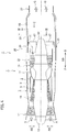
Fig. 1 is a cross-sectional side view of an afterburner according to an embodiment of the present disclosure, which is an enlarged view of part I indicated by an arrow inFig. 4 . -
Fig. 2 is a perspective view of aspect part of the afterburner according to the embodiment of the present disclosure. -
Fig. 3 is an enlarged view taken along a line III-III inFig. 4 . -
Fig. 4 is a cross-sectional side view of the aircraft engine according to the embodiment of the present disclosure. - A description is given of an embodiment of the present disclosure with reference to
Figs. 1 to 4 . In the drawings, F indicates the forward direction (the upstream direction); R, the rearward direction (the downstream direction); SD, the axial direction; RD, the radial direction; and CD, the circumferential direction. - As illustrated in
Fig. 4 , anaircraft engine 1 according to the embodiment of the present disclosure is a device which discharges combustion gas (high-temperature gas) G and air (low-temperature air) A rearward to generate thrust (engine thrust). Theaircraft engine 1 includes a cylindrical core case (an engine inner cylinder) 3, inside of which an annular core flow path (a main flow path) 5 is formed. Outside of thecore case 3, a cylindrical engine case (an engine outer cylinder) 7 is situated concentrically with thecore case 3. Between the inner circumferential surface of theengine case 7 and the outer circumferential surface of thecore case 3, an annular fan flow path (a bypass flow path) 9 is formed. - Within front part of the
engine case 7, afan 11 is situated, which takes air A into thecore flow path 5 andfan flow path 9. In front of the center of thefan 11, aninlet cone 13 guiding the air A rearward is situated. Behind thefan 11, acompressor 15 is situated. Thecompressor 15 compresses the air A taken into thecore flow path 5. Behind thecompressor 15, aburner 17 is situated. Theburner 17 burns the air A containing fuel to generate combustion gas G. - Behind the
burner 17, a high-pressure turbine 19 is situated. The high-pressure turbine 19 is driven by expansion of the combustion gas G from theburner 17 and drives thecompressor 15 in conjunction with the same. Behind the high-pressure turbine 19, a low-pressure turbine 21 is provided. The low-pressure turbine 21 is driven by expansion of the combustion gas G and drives thefan 11 in conjunction with the same. Moreover, within rear part of thecore case 3, atail cone 23 guiding the combustion gas G rearward is provided concentrically with thecore case 3. Thetail cone 23 protrudes rearward from thecore case 3. - In rear part of the
engine case 7, anafterburner 25 is situated. Theafterburner 25 supplies fuel to a gas mixture of the combustion gas G discharged from thecore flow path 5 and the air (low-temperature air) A from thefan flow path 9 for burning (afterburning) to increase the thrust (engine thrust) of theaircraft engine 1. Behind theafterburner 25, anexhaust nozzle 27 is situated. Theexhaust nozzle 27 discharges the combustion gas G and air A (the gas mixture of the combustion gas G and air A). - Next, a description is given of the concrete configuration of the
afterburner 25 according to the embodiment of the present disclosure. - As illustrated in
Figs. 1 to 3 , a rear duct (an exhaust duct) 29 is situated concentrically with theengine case 7 downstream of (behind) theengine case 7. Within therear duct 29, acylindrical liner 31 is situated concentrically with therear duct 29, with plural supports 33 (one of which is illustrated inFig. 1 ) interposed therebetween. Theliner 31 allows the gas mixture to flow rearward. The cross section of theliner 31 along the axial direction (the axial direction of the aircraft engine 1) may be corrugated. Between the outer circumferential surface (the outer wall surface) of theliner 31 and the inner circumferential surface (the inner wall surface) of therear duct 29, an annularcooling flow path 35 is formed, through which a part of the air A discharged from the fan path flow 9 flows as cooling air CA. Moreover, plural penetrating cooling holes 37 are formed evenly across theliner 31. The plural cooling holes 37 are configured to blow out the cooling air CA along the inner circumferential surface of theliner 31. To mix the combustion gas G discharged from thecore flow path 5 and the air A discharged from the fan flow path 9A, a publicly known mixer (not illustrated, seeJP No. 2013-181473 A JP 2012-132630 A core case 3. - The
rear duct 29 is provided with plural hollow stick-shapedfuel injectors 39, which inject liquid fuel within theliner 31. Thefuel injectors 39 are situated at intervals in the circumferential direction (in a predetermined circumferential direction). Theplural fuel injectors 39 are connected to a fuel supply source (not illustrated) which supplies the liquid fuel. The top of eachfuel injector 39 penetrates theliner 31. At the top of eachfuel injector 39, aninjection hole 41 is formed. Theinjection hole 41 can inject the liquid fuel. Downstream of the injection holes 41 (injection places) of thefuel injectors 39 in therear duct 29, plural igniters (ignition plugs) 43 (one of which is illustrated inFig. 3 ) are situated at intervals in the circumferential direction. Theigniters 43 ignite (light) the gas mixture containing the fuel within theliner 31. The top of eachigniter 43 penetrates theliner 31. Instead of the plural hollow stick-shapedfuel injectors 39 provided for therear duct 29, a hollow annular fuel injector (not illustrated) that injects liquid fuel within theliner 31 may be situated on the inner wall surface of theliner 31. - Directly downstream of the injection holes 41 of the
fuel injectors 39 in theliner 31, aflame holder 45 to hold flame is situated. Theframe holder 45 includes plural radialflame holding members 47 and an annulusflame holding member 51. The plural radialflame holding members 47 are situated in a radial fashion within theliner 31 and are capable of propagating flame in the radial direction. The annulusflame holding member 51 is provided on the inner circumferential surface (the inner wall surface) of theliner 31 with plural supports 49 (one of which is illustrated inFig. 1 ) interposed therebetween and is capable of propagating flame in the circumferential direction. The base end (the outside end in the radial direction) of each radialflame holding member 47 is fixed to therear duct 29. The radialflame holding members 47 are capable of forming a flame holding area (low-speed area) FA downstream (directly downstream) thereof. The cross section of each radialflame holding member 47 along the direction orthogonal to the radial direction has a V shape opened downstream. The annulusflame holding member 51 is capable of forming the flame holding area FA downstream (directly downstream) thereof. The inner diameter of the annulusflame holding member 51 decreases with distance towards the downstream end thereof. The annulusflame holding member 51 is provided at a position aligned with the radial flame holding members 47 (at the same position in the axial direction as the radial flame holding members 47) on the circumferential surface of theliner 31. The annulusflame holding member 51 functions as a throttle ring (an annular throttle member) that throttles the main flow of the gas mixture in theliner 31. InFig. 2 , the annulusflame holding member 51 is illustrated as a single annular component. However, the annulusflame holding member 51 may be composed of plural circular flame holding segments (not illustrated) separated in the circumferential direction. The inner circumferential surface side of the annulusflame holding member 51 may be configured to have a double-layered structure so as to form in the inner circumferential surface side of the annulusflame holding member 51, an annular guide flow path (not illustrated) guiding the air A containing the fuel downstream. - Next, a description is given of the operation and effects of the embodiment of the present disclosure.
- When a proper starter device (not illustrated) is operated to drive the
fan 11 andcompressor 15, the air A is taken into thecore flow path 5 andfan flow path 9 by thefan 11, and the air A taken into thecore flow path 5 is compressed by thecompressor 15. The air A containing fuel is then burned by theburner 17 to generate high-pressure combustion gas. By expansion of the combustion gas, the high-pressure turbine 19 and low-pressure turbine 21 are driven to drive thecompressor 15 andfan 11 in conjunction. Moreover, the series of operations (drive of thefan 11, drive of thecompressor 15, burning by theburner 17, drive of the high-pressure turbine 19, and drive of the low-pressure turbine 21) are successively performed to operate theaircraft engine 1. Accordingly, during operation of theaircraft engine 1, the combustion gas G having passed through thecore flow path 5 and the air A having passed through the fan path flow 9 are discharged rearward from theexhaust nozzle 27 to generate thrust of the aircraft engine 1 (engine thrust). The air A discharged from theexhaust nozzle 27 covers the combustion gas G discharged from the exhaust nozzle 27 (normal operation of the aircraft engine 1). - According to a first aspect, the fuel is injected from the
plural fuel injectors 39 in theliner 31 during operation of theaircraft engine 1, and the gas mixture containing the fuel is ignited by theplural igniters 43. Flame is thereby formed downstream (directly downstream) of theflame holder 45 while the gas mixture containing the fuel is burned in the liner 31 (afterburning). A lot of heat energy is thereby put into the combustion gas within theliner 31, thus increasing the thrust of theaircraft engine 1. - On the other hand, a part of the air A discharged from the
fan flow path 9 flows through thecooling flow path 35 as the cooling air CA during operation of theaircraft engine 1. Theliner 31 is therefore convection-cooled. Moreover, the cooling air CA having contributed to the convection cooling of theliner 31 is blown out from the plural cooling holes 37 and forms the film cooling layer (not illustrated) covering the inner circumferential surface of theliner 31. Theliner 31 is therefore film-cooled. The cooling air CA having contributed to the film cooling of theliner 31 becomes a part of the gas mixture (normal operation of the afterburner 25). - The annulus
flame holding member 51 functions as the throttle ring as well as constituting a part of theflame holder 45. This increases the difference in pressure between the outside of theliner 31 and the outlet of the annulusflame holding member 51. The cooling air CA blown out of pluralpredetermined cooling holes 37P (37) (one of which is illustrated inFig. 1 ) located in theframe holder 45 side of the liner 31 (part of theliner 31 aligned with the flame holder 45) therefore forms a stable film cooling layer directly downstream of theflame holder 45 on the inner circumferential surface of theliner 31. It is therefore possible to sufficiently increase the performance of cooling the part of theliner 31 directly downstream of theflame holder 45 without increasing the number of cooling holes 37 located in the part of theliner 31 on theflame holder 45 side or the part thereof upstream of theflame holder 45. - Since the annulus
flame holding member 51 is provided on the inner circumferential surface of theliner 31, theannulus frame member 51 is prevented from interfering with the main flow of the gas mixture within theliner 31, so that pressure loss (thrust loss) in theliner 31 is minimized (aspect operation of the afterburner 25). - According to the embodiment of the present disclosure, it is therefore possible to sufficiently increase the performance of cooling part of the
liner 31 directly downstream of theflame holder 45 without increasing the number of cooling holes 37 located in part of theliner 31 on theflame holder 45 side or the like. This can increase the durability of theliner 31, that is, the durability of theafterburner 25 without reducing the engine efficiency of theaircraft engine 1. Moreover, the pressure loss in theliner 31 is minimized by preventing the interference between the annulusflame holding member 51 and the main flow of the gas mixture within theliner 31. It is therefore possible to further prevent a decrease in engine efficiency of theaircraft engine 1. - The present disclosure is not limited to the description of the above embodiment and can be embodied in various modes. The scope of the present disclosure is not limited to these embodiments.
-
- 1
- AIRCRAFT ENGINE
- 5
- CORE FLOW PATH
- 7
- ENGINE CASE
- 9
- FAN FLOW PATH
- 25
- AFTERBURNER
- 29
- REAR DUCT
- 31
- LINER
- 39
- FUEL INJECTOR
- 43
- IGNITER (IGNITION PLUG)
- 45
- FLAME HOLDER
- 47
- RADIAL FLAME HOLDING MEMBER
- 4
- ANNULUS FLAME HOLDING MEMBER
- A
- AIR
- CA
- COOLING AIR
- FA
- FLAME HOLDING AREA
- G
- COMBUSTION GAS
Claims (3)
- An afterburner which supplies fuel to a gas mixture of combustion gas discharged from a core flow path of an aircraft engine and air discharged from a fan flow path of the aircraft engine for burning to increase thrust of the aircraft engine, the afterburner comprising:a rear duct provided in the outlet side of an engine case of the aircraft engine;a cylindrical liner which is provided within the rear duct and allows the gas mixture to flow,a fuel injector which injects the fuel in the form of liquid in the liner;an igniter which is provided downstream of the fuel injector and ignites the gas mixture containing the fuel in the liner;a flame holder which is situated downstream of the fuel injector and is configured to hold flame, the flame holder including a plurality of radial flame holding members which are situated in a radial fashion inside the liner and propagate flame in the radial direction; anda throttle ring which is provided at a position aligned with the radial flame holding members on the inner circumferential surface of the liner and is configured to throttle the main flow of the gas mixture, whereinbetween the outer circumferential surface of the liner and the inner circumferential surface of the rear duct, an annular cooling path is formed, through which a part of the air discharged from the fan flow path flows as cooling air, andthe liner includes a plurality of penetrating cooling holes to blow out the cooling air along the inner circumferential surface of the liner.
- The afterburner according to claim 1, wherein the throttle ring constitutes a part of the flame holder and is an annulus flame holding member which is provided for the inner circumferential surface of the liner concentrically with the plurality of radial flame holding members and propagates flame in the circumferential direction, and the inner diameter of the annulus flame holding member decreases with distance from the upstream end thereof.
- An aircraft engine which generates thrust by discharging combustion gas rearward, comprising an afterburner according to claim 1 or 2.
Applications Claiming Priority (2)
| Application Number | Priority Date | Filing Date | Title |
|---|---|---|---|
| JP2014093553A JP6229590B2 (en) | 2014-04-30 | 2014-04-30 | Afterburner and aircraft engine |
| PCT/JP2015/062716 WO2015166921A1 (en) | 2014-04-30 | 2015-04-27 | Afterburner and aircraft engine |
Publications (3)
| Publication Number | Publication Date |
|---|---|
| EP3101260A1 true EP3101260A1 (en) | 2016-12-07 |
| EP3101260A4 EP3101260A4 (en) | 2017-09-06 |
| EP3101260B1 EP3101260B1 (en) | 2020-12-09 |
Family
ID=54358648
Family Applications (1)
| Application Number | Title | Priority Date | Filing Date |
|---|---|---|---|
| EP15786393.7A Active EP3101260B1 (en) | 2014-04-30 | 2015-04-27 | Aircraft engine comprising an afterburner |
Country Status (5)
| Country | Link |
|---|---|
| US (1) | US10197011B2 (en) |
| EP (1) | EP3101260B1 (en) |
| JP (1) | JP6229590B2 (en) |
| CA (1) | CA2935810C (en) |
| WO (1) | WO2015166921A1 (en) |
Families Citing this family (10)
| Publication number | Priority date | Publication date | Assignee | Title |
|---|---|---|---|---|
| JP6843513B2 (en) * | 2016-03-29 | 2021-03-17 | 三菱パワー株式会社 | Combustor, how to improve the performance of the combustor |
| GB201610958D0 (en) * | 2016-06-23 | 2016-08-10 | Rolls Royce Plc | Gas turbine exhaust cooling system |
| US11905843B2 (en) * | 2020-04-01 | 2024-02-20 | General Electric Company | Liner support system |
| CN113048511A (en) * | 2021-02-03 | 2021-06-29 | 南京航空航天大学 | Afterburner external culvert mixing device that AI was regulated and control |
| CN113324261B (en) * | 2021-06-07 | 2022-07-05 | 西北工业大学 | Diffuser with rectifying plate and application thereof |
| CN114135401B (en) * | 2021-10-20 | 2023-05-05 | 中国航发四川燃气涡轮研究院 | Adjustable internal mixing device |
| GB2615336A (en) * | 2022-02-04 | 2023-08-09 | Rolls Royce Plc | Reheat assembly for gas turbine engine |
| GB2615335B (en) | 2022-02-04 | 2024-05-08 | Rolls Royce Plc | A reheat assembly |
| GB2615337A (en) * | 2022-02-04 | 2023-08-09 | Rolls Royce Plc | Reheat assembly for gas turbine engine |
| CN115288880A (en) * | 2022-07-25 | 2022-11-04 | 南京航空航天大学 | Exhaust outlet with shielding cooling structure |
Family Cites Families (18)
| Publication number | Priority date | Publication date | Assignee | Title |
|---|---|---|---|---|
| GB852829A (en) * | 1957-04-03 | 1960-11-02 | Rolls Royce | Improvements in or relating to gas-turbine jet propulsion engines |
| US3765178A (en) * | 1972-09-08 | 1973-10-16 | Gen Electric | Afterburner flameholder |
| US3931707A (en) * | 1975-01-08 | 1976-01-13 | General Electric Company | Augmentor flameholding apparatus |
| US4203285A (en) * | 1978-02-06 | 1980-05-20 | The United States Of America As Represented By The Secretary Of The Air Force | Partial swirl augmentor for a turbofan engine |
| FR2696502B1 (en) | 1992-10-07 | 1994-11-04 | Snecma | Post-combustion device for turbofan. |
| US4817378A (en) | 1987-02-13 | 1989-04-04 | General Electric Company | Gas turbine engine with augmentor and variable area bypass injector |
| FR2610994B1 (en) * | 1987-02-13 | 1993-06-11 | Gen Electric | GAS TURBINE ENGINE WITH POSTCOMBUSTION DEVICE AND VARIABLE SECTION DILUTION INJECTOR |
| US5076062A (en) * | 1987-11-05 | 1991-12-31 | General Electric Company | Gas-cooled flameholder assembly |
| GB9127505D0 (en) | 1991-03-11 | 2013-12-25 | Gen Electric | Multi-hole film cooled afterburner combustor liner |
| US5396761A (en) * | 1994-04-25 | 1995-03-14 | General Electric Company | Gas turbine engine ignition flameholder with internal impingement cooling |
| JPH094511A (en) | 1995-06-22 | 1997-01-07 | Mitsubishi Heavy Ind Ltd | Thrust increase method of jet engine with after burner |
| JPH09119346A (en) * | 1995-10-27 | 1997-05-06 | Ishikawajima Harima Heavy Ind Co Ltd | Jet engine frame holder |
| JPH09242609A (en) | 1996-03-11 | 1997-09-16 | Ishikawajima Harima Heavy Ind Co Ltd | Flame retarding device for mixing promotion of jet engine |
| FR2856744B1 (en) * | 2003-06-25 | 2007-05-25 | Snecma Moteurs | VENTILATION CHANNELS ON POST-COMBUSTION CHAMBER CONFLUENCE ROOF |
| US20060137352A1 (en) | 2004-12-29 | 2006-06-29 | United Technologies Corporation | Augmentor liner |
| US7437876B2 (en) * | 2005-03-25 | 2008-10-21 | General Electric Company | Augmenter swirler pilot |
| US7565804B1 (en) | 2006-06-29 | 2009-07-28 | General Electric Company | Flameholder fuel shield |
| US7568346B2 (en) * | 2006-10-31 | 2009-08-04 | General Electric Company | Method and apparatus for assembling a flameholder for an augmenter |
-
2014
- 2014-04-30 JP JP2014093553A patent/JP6229590B2/en active Active
-
2015
- 2015-04-27 WO PCT/JP2015/062716 patent/WO2015166921A1/en not_active Ceased
- 2015-04-27 CA CA2935810A patent/CA2935810C/en active Active
- 2015-04-27 EP EP15786393.7A patent/EP3101260B1/en active Active
-
2016
- 2016-06-27 US US15/193,286 patent/US10197011B2/en active Active
Also Published As
| Publication number | Publication date |
|---|---|
| EP3101260A4 (en) | 2017-09-06 |
| WO2015166921A1 (en) | 2015-11-05 |
| US20170089300A1 (en) | 2017-03-30 |
| JP2015209834A (en) | 2015-11-24 |
| US10197011B2 (en) | 2019-02-05 |
| CA2935810C (en) | 2018-05-15 |
| CA2935810A1 (en) | 2015-11-05 |
| EP3101260B1 (en) | 2020-12-09 |
| JP6229590B2 (en) | 2017-11-15 |
Similar Documents
| Publication | Publication Date | Title |
|---|---|---|
| CA2935810C (en) | Afterburner and aircraft engine | |
| EP2354663B1 (en) | Gas turbine combustor with staged combustion | |
| EP2821627B1 (en) | Afterburner and aircraft engine | |
| US9068748B2 (en) | Axial stage combustor for gas turbine engines | |
| EP1710424A2 (en) | Fuel/air swirler for a turbofan engine augmenter | |
| US10704787B2 (en) | Closed trapped vortex cavity pilot for a gas turbine engine augmentor | |
| EP2400221B1 (en) | Ejector purge of cavity adjacent exhaust flowpath | |
| US10168050B2 (en) | Afterburner and aircraft engine | |
| JP6693227B2 (en) | Afterburners and aircraft engines | |
| JP3974595B2 (en) | Turbine engine augmentor and method of operating the same | |
| CA2516753A1 (en) | Methods and apparatus for reducing gas turbine engine emissions | |
| US10436117B2 (en) | Carbureted fuel injection system for a gas turbine engine |
Legal Events
| Date | Code | Title | Description |
|---|---|---|---|
| PUAI | Public reference made under article 153(3) epc to a published international application that has entered the european phase |
Free format text: ORIGINAL CODE: 0009012 |
|
| STAA | Information on the status of an ep patent application or granted ep patent |
Free format text: STATUS: REQUEST FOR EXAMINATION WAS MADE |
|
| 17P | Request for examination filed |
Effective date: 20160901 |
|
| AK | Designated contracting states |
Kind code of ref document: A1 Designated state(s): AL AT BE BG CH CY CZ DE DK EE ES FI FR GB GR HR HU IE IS IT LI LT LU LV MC MK MT NL NO PL PT RO RS SE SI SK SM TR |
|
| AX | Request for extension of the european patent |
Extension state: BA ME |
|
| REG | Reference to a national code |
Ref country code: DE Ref legal event code: R079 Ref document number: 602015063287 Country of ref document: DE Free format text: PREVIOUS MAIN CLASS: F02K0003100000 Ipc: F23R0003200000 |
|
| DAV | Request for validation of the european patent (deleted) | ||
| DAX | Request for extension of the european patent (deleted) | ||
| A4 | Supplementary search report drawn up and despatched |
Effective date: 20170804 |
|
| RIC1 | Information provided on ipc code assigned before grant |
Ipc: F02K 3/10 20060101ALI20170731BHEP Ipc: F23R 3/20 20060101AFI20170731BHEP |
|
| STAA | Information on the status of an ep patent application or granted ep patent |
Free format text: STATUS: EXAMINATION IS IN PROGRESS |
|
| 17Q | First examination report despatched |
Effective date: 20190218 |
|
| GRAP | Despatch of communication of intention to grant a patent |
Free format text: ORIGINAL CODE: EPIDOSNIGR1 |
|
| STAA | Information on the status of an ep patent application or granted ep patent |
Free format text: STATUS: GRANT OF PATENT IS INTENDED |
|
| INTG | Intention to grant announced |
Effective date: 20200706 |
|
| GRAS | Grant fee paid |
Free format text: ORIGINAL CODE: EPIDOSNIGR3 |
|
| GRAA | (expected) grant |
Free format text: ORIGINAL CODE: 0009210 |
|
| STAA | Information on the status of an ep patent application or granted ep patent |
Free format text: STATUS: THE PATENT HAS BEEN GRANTED |
|
| AK | Designated contracting states |
Kind code of ref document: B1 Designated state(s): AL AT BE BG CH CY CZ DE DK EE ES FI FR GB GR HR HU IE IS IT LI LT LU LV MC MK MT NL NO PL PT RO RS SE SI SK SM TR |
|
| REG | Reference to a national code |
Ref country code: GB Ref legal event code: FG4D |
|
| REG | Reference to a national code |
Ref country code: AT Ref legal event code: REF Ref document number: 1343839 Country of ref document: AT Kind code of ref document: T Effective date: 20201215 Ref country code: CH Ref legal event code: EP |
|
| REG | Reference to a national code |
Ref country code: DE Ref legal event code: R096 Ref document number: 602015063287 Country of ref document: DE |
|
| REG | Reference to a national code |
Ref country code: IE Ref legal event code: FG4D |
|
| PG25 | Lapsed in a contracting state [announced via postgrant information from national office to epo] |
Ref country code: NO Free format text: LAPSE BECAUSE OF FAILURE TO SUBMIT A TRANSLATION OF THE DESCRIPTION OR TO PAY THE FEE WITHIN THE PRESCRIBED TIME-LIMIT Effective date: 20210309 Ref country code: FI Free format text: LAPSE BECAUSE OF FAILURE TO SUBMIT A TRANSLATION OF THE DESCRIPTION OR TO PAY THE FEE WITHIN THE PRESCRIBED TIME-LIMIT Effective date: 20201209 Ref country code: RS Free format text: LAPSE BECAUSE OF FAILURE TO SUBMIT A TRANSLATION OF THE DESCRIPTION OR TO PAY THE FEE WITHIN THE PRESCRIBED TIME-LIMIT Effective date: 20201209 Ref country code: GR Free format text: LAPSE BECAUSE OF FAILURE TO SUBMIT A TRANSLATION OF THE DESCRIPTION OR TO PAY THE FEE WITHIN THE PRESCRIBED TIME-LIMIT Effective date: 20210310 |
|
| REG | Reference to a national code |
Ref country code: AT Ref legal event code: MK05 Ref document number: 1343839 Country of ref document: AT Kind code of ref document: T Effective date: 20201209 |
|
| PG25 | Lapsed in a contracting state [announced via postgrant information from national office to epo] |
Ref country code: BG Free format text: LAPSE BECAUSE OF FAILURE TO SUBMIT A TRANSLATION OF THE DESCRIPTION OR TO PAY THE FEE WITHIN THE PRESCRIBED TIME-LIMIT Effective date: 20210309 Ref country code: SE Free format text: LAPSE BECAUSE OF FAILURE TO SUBMIT A TRANSLATION OF THE DESCRIPTION OR TO PAY THE FEE WITHIN THE PRESCRIBED TIME-LIMIT Effective date: 20201209 Ref country code: LV Free format text: LAPSE BECAUSE OF FAILURE TO SUBMIT A TRANSLATION OF THE DESCRIPTION OR TO PAY THE FEE WITHIN THE PRESCRIBED TIME-LIMIT Effective date: 20201209 |
|
| REG | Reference to a national code |
Ref country code: NL Ref legal event code: MP Effective date: 20201209 |
|
| PG25 | Lapsed in a contracting state [announced via postgrant information from national office to epo] |
Ref country code: HR Free format text: LAPSE BECAUSE OF FAILURE TO SUBMIT A TRANSLATION OF THE DESCRIPTION OR TO PAY THE FEE WITHIN THE PRESCRIBED TIME-LIMIT Effective date: 20201209 Ref country code: NL Free format text: LAPSE BECAUSE OF FAILURE TO SUBMIT A TRANSLATION OF THE DESCRIPTION OR TO PAY THE FEE WITHIN THE PRESCRIBED TIME-LIMIT Effective date: 20201209 |
|
| REG | Reference to a national code |
Ref country code: LT Ref legal event code: MG9D |
|
| PG25 | Lapsed in a contracting state [announced via postgrant information from national office to epo] |
Ref country code: RO Free format text: LAPSE BECAUSE OF FAILURE TO SUBMIT A TRANSLATION OF THE DESCRIPTION OR TO PAY THE FEE WITHIN THE PRESCRIBED TIME-LIMIT Effective date: 20201209 Ref country code: PT Free format text: LAPSE BECAUSE OF FAILURE TO SUBMIT A TRANSLATION OF THE DESCRIPTION OR TO PAY THE FEE WITHIN THE PRESCRIBED TIME-LIMIT Effective date: 20210409 Ref country code: SK Free format text: LAPSE BECAUSE OF FAILURE TO SUBMIT A TRANSLATION OF THE DESCRIPTION OR TO PAY THE FEE WITHIN THE PRESCRIBED TIME-LIMIT Effective date: 20201209 Ref country code: LT Free format text: LAPSE BECAUSE OF FAILURE TO SUBMIT A TRANSLATION OF THE DESCRIPTION OR TO PAY THE FEE WITHIN THE PRESCRIBED TIME-LIMIT Effective date: 20201209 Ref country code: EE Free format text: LAPSE BECAUSE OF FAILURE TO SUBMIT A TRANSLATION OF THE DESCRIPTION OR TO PAY THE FEE WITHIN THE PRESCRIBED TIME-LIMIT Effective date: 20201209 Ref country code: CZ Free format text: LAPSE BECAUSE OF FAILURE TO SUBMIT A TRANSLATION OF THE DESCRIPTION OR TO PAY THE FEE WITHIN THE PRESCRIBED TIME-LIMIT Effective date: 20201209 Ref country code: SM Free format text: LAPSE BECAUSE OF FAILURE TO SUBMIT A TRANSLATION OF THE DESCRIPTION OR TO PAY THE FEE WITHIN THE PRESCRIBED TIME-LIMIT Effective date: 20201209 |
|
| PG25 | Lapsed in a contracting state [announced via postgrant information from national office to epo] |
Ref country code: AT Free format text: LAPSE BECAUSE OF FAILURE TO SUBMIT A TRANSLATION OF THE DESCRIPTION OR TO PAY THE FEE WITHIN THE PRESCRIBED TIME-LIMIT Effective date: 20201209 Ref country code: PL Free format text: LAPSE BECAUSE OF FAILURE TO SUBMIT A TRANSLATION OF THE DESCRIPTION OR TO PAY THE FEE WITHIN THE PRESCRIBED TIME-LIMIT Effective date: 20201209 |
|
| REG | Reference to a national code |
Ref country code: DE Ref legal event code: R097 Ref document number: 602015063287 Country of ref document: DE |
|
| PG25 | Lapsed in a contracting state [announced via postgrant information from national office to epo] |
Ref country code: IS Free format text: LAPSE BECAUSE OF FAILURE TO SUBMIT A TRANSLATION OF THE DESCRIPTION OR TO PAY THE FEE WITHIN THE PRESCRIBED TIME-LIMIT Effective date: 20210409 |
|
| PLBE | No opposition filed within time limit |
Free format text: ORIGINAL CODE: 0009261 |
|
| STAA | Information on the status of an ep patent application or granted ep patent |
Free format text: STATUS: NO OPPOSITION FILED WITHIN TIME LIMIT |
|
| PG25 | Lapsed in a contracting state [announced via postgrant information from national office to epo] |
Ref country code: IT Free format text: LAPSE BECAUSE OF FAILURE TO SUBMIT A TRANSLATION OF THE DESCRIPTION OR TO PAY THE FEE WITHIN THE PRESCRIBED TIME-LIMIT Effective date: 20201209 Ref country code: AL Free format text: LAPSE BECAUSE OF FAILURE TO SUBMIT A TRANSLATION OF THE DESCRIPTION OR TO PAY THE FEE WITHIN THE PRESCRIBED TIME-LIMIT Effective date: 20201209 |
|
| 26N | No opposition filed |
Effective date: 20210910 |
|
| PG25 | Lapsed in a contracting state [announced via postgrant information from national office to epo] |
Ref country code: MC Free format text: LAPSE BECAUSE OF FAILURE TO SUBMIT A TRANSLATION OF THE DESCRIPTION OR TO PAY THE FEE WITHIN THE PRESCRIBED TIME-LIMIT Effective date: 20201209 Ref country code: DK Free format text: LAPSE BECAUSE OF FAILURE TO SUBMIT A TRANSLATION OF THE DESCRIPTION OR TO PAY THE FEE WITHIN THE PRESCRIBED TIME-LIMIT Effective date: 20201209 Ref country code: ES Free format text: LAPSE BECAUSE OF FAILURE TO SUBMIT A TRANSLATION OF THE DESCRIPTION OR TO PAY THE FEE WITHIN THE PRESCRIBED TIME-LIMIT Effective date: 20201209 Ref country code: SI Free format text: LAPSE BECAUSE OF FAILURE TO SUBMIT A TRANSLATION OF THE DESCRIPTION OR TO PAY THE FEE WITHIN THE PRESCRIBED TIME-LIMIT Effective date: 20201209 |
|
| PG25 | Lapsed in a contracting state [announced via postgrant information from national office to epo] |
Ref country code: LU Free format text: LAPSE BECAUSE OF NON-PAYMENT OF DUE FEES Effective date: 20210427 |
|
| REG | Reference to a national code |
Ref country code: BE Ref legal event code: MM Effective date: 20210430 |
|
| PG25 | Lapsed in a contracting state [announced via postgrant information from national office to epo] |
Ref country code: CH Free format text: LAPSE BECAUSE OF NON-PAYMENT OF DUE FEES Effective date: 20210430 Ref country code: LI Free format text: LAPSE BECAUSE OF NON-PAYMENT OF DUE FEES Effective date: 20210430 |
|
| PG25 | Lapsed in a contracting state [announced via postgrant information from national office to epo] |
Ref country code: IE Free format text: LAPSE BECAUSE OF NON-PAYMENT OF DUE FEES Effective date: 20210427 |
|
| PG25 | Lapsed in a contracting state [announced via postgrant information from national office to epo] |
Ref country code: IS Free format text: LAPSE BECAUSE OF FAILURE TO SUBMIT A TRANSLATION OF THE DESCRIPTION OR TO PAY THE FEE WITHIN THE PRESCRIBED TIME-LIMIT Effective date: 20210409 |
|
| PG25 | Lapsed in a contracting state [announced via postgrant information from national office to epo] |
Ref country code: BE Free format text: LAPSE BECAUSE OF NON-PAYMENT OF DUE FEES Effective date: 20210430 |
|
| PG25 | Lapsed in a contracting state [announced via postgrant information from national office to epo] |
Ref country code: HU Free format text: LAPSE BECAUSE OF FAILURE TO SUBMIT A TRANSLATION OF THE DESCRIPTION OR TO PAY THE FEE WITHIN THE PRESCRIBED TIME-LIMIT; INVALID AB INITIO Effective date: 20150427 |
|
| PG25 | Lapsed in a contracting state [announced via postgrant information from national office to epo] |
Ref country code: CY Free format text: LAPSE BECAUSE OF FAILURE TO SUBMIT A TRANSLATION OF THE DESCRIPTION OR TO PAY THE FEE WITHIN THE PRESCRIBED TIME-LIMIT Effective date: 20201209 |
|
| PG25 | Lapsed in a contracting state [announced via postgrant information from national office to epo] |
Ref country code: MK Free format text: LAPSE BECAUSE OF FAILURE TO SUBMIT A TRANSLATION OF THE DESCRIPTION OR TO PAY THE FEE WITHIN THE PRESCRIBED TIME-LIMIT Effective date: 20201209 |
|
| PG25 | Lapsed in a contracting state [announced via postgrant information from national office to epo] |
Ref country code: MT Free format text: LAPSE BECAUSE OF FAILURE TO SUBMIT A TRANSLATION OF THE DESCRIPTION OR TO PAY THE FEE WITHIN THE PRESCRIBED TIME-LIMIT Effective date: 20201209 |
|
| PGFP | Annual fee paid to national office [announced via postgrant information from national office to epo] |
Ref country code: DE Payment date: 20250319 Year of fee payment: 11 |
|
| PG25 | Lapsed in a contracting state [announced via postgrant information from national office to epo] |
Ref country code: TR Free format text: LAPSE BECAUSE OF FAILURE TO SUBMIT A TRANSLATION OF THE DESCRIPTION OR TO PAY THE FEE WITHIN THE PRESCRIBED TIME-LIMIT Effective date: 20201209 |
|
| PGFP | Annual fee paid to national office [announced via postgrant information from national office to epo] |
Ref country code: GB Payment date: 20260319 Year of fee payment: 12 |
|
| PGFP | Annual fee paid to national office [announced via postgrant information from national office to epo] |
Ref country code: FR Payment date: 20260319 Year of fee payment: 12 |