EP3100798A1 - Die for ironing process, and shaped material production method - Google Patents
Die for ironing process, and shaped material production method Download PDFInfo
- Publication number
- EP3100798A1 EP3100798A1 EP14879298.9A EP14879298A EP3100798A1 EP 3100798 A1 EP3100798 A1 EP 3100798A1 EP 14879298 A EP14879298 A EP 14879298A EP 3100798 A1 EP3100798 A1 EP 3100798A1
- Authority
- EP
- European Patent Office
- Prior art keywords
- folded
- punch
- formed portion
- drawn formed
- ironing
- Prior art date
- Legal status (The legal status is an assumption and is not a legal conclusion. Google has not performed a legal analysis and makes no representation as to the accuracy of the status listed.)
- Granted
Links
Images


Classifications
-
- B—PERFORMING OPERATIONS; TRANSPORTING
- B21—MECHANICAL METAL-WORKING WITHOUT ESSENTIALLY REMOVING MATERIAL; PUNCHING METAL
- B21D—WORKING OR PROCESSING OF SHEET METAL OR METAL TUBES, RODS OR PROFILES WITHOUT ESSENTIALLY REMOVING MATERIAL; PUNCHING METAL
- B21D22/00—Shaping without cutting, by stamping, spinning, or deep-drawing
- B21D22/20—Deep-drawing
- B21D22/30—Deep-drawing to finish articles formed by deep-drawing
-
- B—PERFORMING OPERATIONS; TRANSPORTING
- B21—MECHANICAL METAL-WORKING WITHOUT ESSENTIALLY REMOVING MATERIAL; PUNCHING METAL
- B21D—WORKING OR PROCESSING OF SHEET METAL OR METAL TUBES, RODS OR PROFILES WITHOUT ESSENTIALLY REMOVING MATERIAL; PUNCHING METAL
- B21D22/00—Shaping without cutting, by stamping, spinning, or deep-drawing
- B21D22/20—Deep-drawing
- B21D22/28—Deep-drawing of cylindrical articles using consecutive dies
-
- B—PERFORMING OPERATIONS; TRANSPORTING
- B21—MECHANICAL METAL-WORKING WITHOUT ESSENTIALLY REMOVING MATERIAL; PUNCHING METAL
- B21D—WORKING OR PROCESSING OF SHEET METAL OR METAL TUBES, RODS OR PROFILES WITHOUT ESSENTIALLY REMOVING MATERIAL; PUNCHING METAL
- B21D37/00—Tools as parts of machines covered by this subclass
- B21D37/10—Die sets; Pillar guides
Definitions
- the folded and drawn formed portion when the folded and drawn formed portion is pushed into the pushing hole, the folded and drawn formed portion is ironed and thinned by the shoulder portion of the die, from the fold portion on the front end side towards the counter pad side.
- the material plate thickness is greater towards the counter pad side, and the thick portion of the folded and drawn formed portion is subjected to a greater amount of ironing. Therefore, a surface treated layer of the portion of increased thickness is shaved, and therefore a powdery residue may be generated.
- the powdery residue causes problems such as formation of minute pockmarks (dents) in the surface of the formed portion after ironing, and deterioration of the performance of a product made using the formed material.
- the radius r of the shoulder portion 211 is too large, then the gap between the punch 20 and the die 21 becomes too large, which leads conversely to deterioration in the dimensional precision.
- the radius r of the shoulder portion 211 is too large, then the inner peripheral wall 10 and the outer peripheral wall 11 deform greatly along the curved surface of the shoulder portion 211.
- the skewness Rsk represents the probability of the existence of projecting portions in the irregularities 13a on the coating layer 13 (see Fig. 7 ). As the skewness Rsk becomes smaller, the number of projecting portions decreases and the amount of generated coating residue is suppressed.
- the skewness Rsk has been explained by the present applicant in Japanese Patent Application Publication No. 2006-193776 .
Landscapes
- Engineering & Computer Science (AREA)
- Mechanical Engineering (AREA)
- Shaping Metal By Deep-Drawing, Or The Like (AREA)
- Organic Low-Molecular-Weight Compounds And Preparation Thereof (AREA)
Abstract
Description
- The present invention relates to an ironing mold used to perform ironing on a folded and drawn formed portion, and a formed material manufacturing method.
- A ring-shaped folded and drawn formed portion is typically formed by press forming such as drawing using a surface treated metal plate such as a coated steel plate as a raw material. For example, in
PTL 1, a ring-shaped oil groove 17 is formed by a folding and drawing process in a portion of ahousing 1 of an electric motor. The folded and drawn formed portion is a portion which is formed by folding a single sheet member, and includes an inner peripheral wall, an outer peripheral wall, and a fold portion which links the front ends of the inner peripheral wall and the outer peripheral wall. When the folded and drawn formed portion requires particularly high dimensional precision, ironing is implemented on the folded and drawn formed portion after the folded and drawn formed portion has been formed. Ironing is a process in which a clearance between a punch and a die is set to be narrower than a thickness of the folded and drawn formed portion prior to ironing, and the folded and drawn formed portion is then ironed using the punch and the die so that the thickness of the folded and drawn formed portion matches the clearance between the punch and the die. Ironing for a folded and drawn formed portion of this kind is also known as a "restrike". - The folded and drawn formed portion is formed by a mold which is generally configured in the following manner. In other words, a conventional mold is provided with a punch, a die, and a counter pad part. The punch is configured as a columnar member, and the die is configured as a ring-shaped member which is disposed on the outer periphery of the punch. A pushing hole into which the folded and drawn formed portion is pushed is formed between the punch and the die. The die has a shoulder portion disposed on an outer edge of an inlet of the pushing hole and constituted by a curved surface having a predetermined curvature radius, and an inner peripheral surface which extends linearly parallel to the pushing direction from a radius end of the shoulder portion. The outer peripheral surface of the punch and the inner peripheral surface of the pushing hole extend mutually in parallel along the pushing direction of the folded and drawn formed portion.
- The counter pad part is a member which is arranged facing the punch and the die in such a manner that the folded and drawn formed portion is positioned between the punch and the die, and the counter pad part pushes the folded and drawn formed portion into the pushing hole by relative displacement of the counter pad part with respect to the punch and the die. The wall surface of the outer peripheral wall of the folded and drawn formed portion is ironed by the shoulder portion when pushed into the pushing hole, and the whole folded and drawn formed portion is gradually thinned until coinciding with the width of the clearance between the outer peripheral surface of the punch and the inner peripheral surface of the pushing hole.
- [PTL 1]
Japanese Patent Application Publication No. 2012-167818 - In general, when the folded and drawn formed portion is pushed into the pushing hole, the folded and drawn formed portion is ironed and thinned by the shoulder portion of the die, from the fold portion on the front end side towards the counter pad side. In this case, since the thinned material is pushed towards the counter pad side, then the material plate thickness is greater towards the counter pad side, and the thick portion of the folded and drawn formed portion is subjected to a greater amount of ironing. Therefore, a surface treated layer of the portion of increased thickness is shaved, and therefore a powdery residue may be generated. The powdery residue causes problems such as formation of minute pockmarks (dents) in the surface of the formed portion after ironing, and deterioration of the performance of a product made using the formed material. Furthermore, when the radius of the shoulder portion of the die is small, then at the bottom dead center of the pressing action, the material which has been pushed by the ironing is crushed between the counter pad and the punch and the die, and generates a large residual compressive stress. This residual compressive stress is a cause of dimensional variation due to elastic deformation, in the product when released from the mold after forming.
- The present invention was devised in order to resolve the problems described above, an object thereof being to provide an ironing mold and a formed material manufacturing method whereby the generation of a large load on a part of a surface treated layer can be avoided, an amount of generated powdery residue can be reduced, and deterioration in the dimensional precision of the folded and drawn formed portion after ironing can be prevented.
- The ironing mold according to the present invention is an ironing mold for performing ironing on a folded and drawn formed portion which is formed using a surface treated metal plate as a raw material and which has an inner peripheral wall, an outer peripheral wall and a fold portion linking front ends of the inner peripheral wall and the outer peripheral wall, including: a punch; a die which is disposed on the outer periphery of the punch and which forms, with respect to the punch, a pushing hole into which the folded and drawn formed portion is pushed with the fold portion to the front; and a counter pad part which is disposed facing the punch and the die in such a manner that the folded and drawn formed portion is positioned between the punch and the die, and which pushes the folded and drawn formed portion into the pushing hole by relative displacement of the counter pad part with respect to the punch and the die, wherein the die includes a shoulder portion disposed on an outer edge of an inlet of the pushing hole and constituted by a curved surface having a predetermined curvature radius, and an inner peripheral surface which extends from a radius end of the shoulder portion in a pushing direction of the folded and drawn formed portion, and along which a surface of the outer peripheral wall of the folded and drawn formed portion slides in response to the pushing of the folded and drawn formed portion; a skewness Rsk of the surface treated metal plate is less than -0.6 and no less than -1.3; the curvature radius of the shoulder portion and the clearance between the radius end and the punch are determined such that, when the curvature radius of the shoulder portion is represented by r, the clearance between the radius end and the punch is represented by Cre, a thickness of the folded and drawn formed portion prior to the ironing at a position that is sandwiched between the radius end and the punch upon completion of the ironing is represented by tre and a height of the folded and drawn formed portion is represented by h, then Y, which is expressed by {(tre - Cre)/tre} × 100, and X, which is expressed by r/tre, satisfy 0 < Y ≤ 18.7X - 6.1, X satisfies X ≥ 0.6, and r satisfies r ≤ 0.5h.
- Furthermore, the ironing mold according to the present invention is an ironing mold for performing ironing on a folded and drawn formed portion which is formed using a surface treated metal plate as a raw material and which has an inner peripheral wall, an outer peripheral wall and a fold portion linking front ends of the inner peripheral wall and the outer peripheral wall, including: a punch; a die which is disposed on the outer periphery of the punch and which forms, with respect to the punch, a pushing hole into which the folded and drawn formed portion is pushed with the fold portion to the front; and a counter pad part which is disposed facing the punch and the die in such a manner that the folded and drawn formed portion is positioned between the punch and the die, and which pushes the folded and drawn formed portion into the pushing hole by relative displacement of the counter pad part with respect to the punch and the die, wherein the die includes a shoulder portion disposed on an outer edge of an inlet of the pushing hole and constituted by a curved surface having a predetermined curvature radius, and an inner peripheral surface which extends from a radius end of the shoulder portion in a pushing direction of the folded and drawn formed portion, and along which a surface of the outer peripheral wall of the folded and drawn formed portion slides in response to the pushing of the folded and drawn formed portion; a skewness Rsk of the surface treated metal plate is no less than -0.6 and no more than 0; the curvature radius of the shoulder portion and the clearance between the radius end and the punch are determined such that, when the curvature radius of the shoulder portion is represented by r, the clearance between the radius end and the punch is represented by Cre, a thickness of the folded and drawn formed portion prior to the ironing at a position that is sandwiched between the radius end and the punch upon completion of the ironing is represented by tre and a height of the folded and drawn formed portion is represented by h, then Y, which is expressed by {(tre - Cre)/tre} × 100, and X, which is expressed by r/tre, satisfy 0 < Y ≤ 14.4X - 6.4, X satisfies X ≥ 0.8, and r satisfies r ≤ 0.5h.
- The formed material manufacturing method according to the present invention is a formed material manufacturing method including the steps of: forming a ring-shaped folded and drawn formed portion having an inner peripheral wall, an outer peripheral wall and a fold portion linking front ends of the inner peripheral wall and the outer peripheral wall, by performing at least one forming process on a surface treated metal plate; and performing ironing on the folded and drawn formed portion using an ironing mold after forming the folded and drawn formed portion, wherein the ironing mold includes: a punch; a die which is disposed on the outer periphery of the punch and which forms, with respect to the punch, a pushing hole into which the folded and drawn formed portion is pushed with the fold portion to the front; and a counter pad part which is disposed facing the punch and the die in such a manner that the folded and drawn formed portion is positioned between the punch and the die, and which pushes the folded and drawn formed portion into the pushing hole by relative displacement of the counter pad part with respect to the punch and the die, the die includes a shoulder portion disposed on an outer edge of an inlet of the pushing hole and constituted by a curved surface having a predetermined curvature radius, and an inner peripheral surface which extends from a radius end of the shoulder portion in a pushing direction of the folded and drawn formed portion, and along which a surface of the outer peripheral wall of the folded and drawn formed portion slides in response to the pushing of the folded and drawn formed portion; a skewness Rsk of the surface treated metal plate is less than -0.6 and no less than -1.3; and the curvature radius of the shoulder portion and the clearance between the radius end and the punch are determined such that, when the curvature radius of the shoulder portion is represented by r, the clearance between the radius end and the punch is represented by Cre, a thickness of the folded and drawn formed portion prior to the ironing at a position that is sandwiched between the radius end and the punch upon completion of the ironing is represented by tre and a height of the folded and drawn formed portion is represented by h, then Y, which is expressed by {(tre - Cre)/tre} × 100, and X, which is expressed by r/tre, satisfy 0 < Y ≤ 18.7X - 6.1, X satisfies X ≥ 0.6, and r satisfies r ≤ 0.5h.
- Furthermore, the formed material manufacturing method according to the present invention is a formed material manufacturing method including the steps of: forming a ring-shaped folded and drawn formed portion having an inner peripheral wall, an outer peripheral wall and a fold portion linking front ends of the inner peripheral wall and the outer peripheral wall, by performing at least one forming process on a surface treated metal plate; and performing ironing on the folded and drawn formed portion using an ironing mold after forming the folded and drawn formed portion, wherein the ironing mold includes: a punch; a die which is disposed on the outer periphery of the punch and which forms, with respect to the punch, a pushing hole into which the folded and drawn formed portion is pushed with the fold portion to the front; a counter pad part which is disposed facing the punch and the die in such a manner that the folded and drawn formed portion is positioned between the punch and the die, and which pushes the folded and drawn formed portion into the pushing hole by relative displacement of the counter pad part with respect to the punch and the die, the die includes a shoulder portion disposed on an outer edge of an inlet of the pushing hole and constituted by a curved surface having a predetermined curvature radius, and an inner peripheral surface which extends from a radius end of the shoulder portion in a pushing direction of the folded and drawn formed portion, and along which a surface of the outer peripheral wall of the folded and drawn formed portion slides in response to the pushing of the folded and drawn formed portion; a skewness Rsk of the surface treated metal plate is no less than -0.6 and no more than 0; and the curvature radius of the shoulder portion and the clearance between the radius end and the punch are determined such that, when the curvature radius of the shoulder portion is represented by r, the clearance between the radius end and the punch is represented by Cre, a thickness of the folded and drawn formed portion prior to the ironing at a position that is sandwiched between the radius end and the punch upon completion of the ironing is represented by tre and a height of the folded and drawn formed portion is represented by h, then Y, which is expressed by {(tre - Cre)/tre} × 100, and X, which is expressed by r/tre, satisfy 0 < Y ≤ 14.4X - 6.4, X satisfies X ≥ 0.8, and r satisfies r ≤ 0.5h.
- According to the ironing mold and the formed material manufacturing method of the present invention, since the pushing hole is configured in such a manner that the material pushed by the ironing of the folded and drawn formed portion is not crushed excessively between the punch and the die and the counter pad, at the bottom dead center of the pressing action, then the generation of a large load on a part of the surface treated layer can be avoided, and deformation after separation from the mold can also be reduced. Consequently, the amount of generated powdery residue can be reduced, and deterioration in the dimensional precision of the folded and drawn formed portion after ironing can be prevented.
-
- [
Fig. 1 ]
Fig. 1 is a flowchart showing a formed material manufacturing method according to an embodiment of the present invention. - [
Fig. 2 ]
Fig. 2 is a cross-sectional diagram of a formed material including a folded and drawn formed portion which is formed in the forming step S1 inFig. 1 . - [
Fig. 3 ]
Fig. 3 is a cross-sectional diagram of a formed material including a folded and drawn formed portion after carrying out an ironing process S2 inFig. 1 . - [
Fig. 4 ]
Fig. 4 is a cross-sectional diagram showing an enlarged view of one portion of the folded and drawn formed portion inFig. 2 . - [
Fig. 5 ]
Fig. 5 is a cross-sectional diagram of an ironing mold used in the ironing process S2 inFig. 1 . - [
Fig. 6 ]
Fig. 6 is an illustrative diagram showing an enlarged view of the periphery of a shoulder portion in a state where ironing is being performed on a formed portion using the ironing mold inFig. 5 . - [
Fig. 7 ]
Fig. 7 is a schematic illustrative view showing a relationship between the shoulder portion and a coating layer of a Zn coated steel plate inFig. 6 . - [
Fig. 8 ]
Fig. 8 is a graph showing a skewness Rsk of the coating layer inFig. 7 , for coating layers of various types. - [
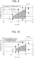
Fig. 9 ]
Fig. 9 is a graph showing a relationship between an ironing rate Y and X (= r/tre) in relation to a Zn-Al-Mg alloy coated steel plate. - [
Fig. 10 ]
Fig. 10 is a graph showing the relationship between the ironing rate Y and X (= r/tre) in relation to a hot dip galvannealed steel plate, a hot dip galvanized steel plate, and an electro-galvanized steel plate shown inFig. 8 . - Below, an embodiment of this invention is described with reference to the drawings.
-
Fig. 1 is a flowchart showing a formed material manufacturing method according to an embodiment of the present invention,Fig. 2 is a cross-sectional diagram of a formed material including a folded and drawn formedportion 1 which is formed by the forming process S1 inFig. 1 , andFig. 3 is a cross-sectional diagram of a formed material including a folded and drawn formedportion 1 after carrying out the ironing process S2 inFig. 1 . - As shown in
Fig. 1 , the formed material manufacturing method according to the present embodiment includes a forming process S1 and the ironing process S2. The forming process S1 is a step for forming a ring-shaped folded and drawn formed portion 1 (seeFig. 2 ) by performing at least one forming process on a surface-treated metal plate. The forming process includes a pressing process, such as a drawing process or stretching. The surface treated metal plate is a metal plate having a surface treated layer on a surface thereof. The surface treated layer includes a painted film or a coating layer. In the present embodiment, the surface treated metal plate is described as a Zn (zinc) coated steel plate formed by applying a Zn coating to a surface of a steel plate. - As shown in
Fig. 2 , the folded and drawn formedportion 1 according to this embodiment is a ring-shaped wall formed by forming the Zn coated steel plate into a cap body, and then forming the plate so as to project towards the inside of the cap body from the apex portion of the cap body, and the folded and drawn formedportion 1 includes an innerperipheral wall 10 and an outerperipheral wall 11, and afold portion 12 which links the front ends of the innerperipheral wall 10 and the outerperipheral wall 11. Hereafter, a direction extending from abase portion 1b (the rear end side of the innerperipheral wall 10 and the outer peripheral wall 11) to anapex portion 1a (fold portion 12) of the folded and drawn formedportion 1 is called the pushingdirection 1c. The pushingdirection 1c means a direction in which the folded and drawn formedportion 1 is pushed into a pushing hole (seeFig. 5 ) that is provided in a die of the ironing mold which is described below. - The ironing process S2 is a process for performing ironing on the folded and drawn formed
portion 1 by using the ironing mold described below. Ironing is a process in which a clearance between a punch and a die of an ironing mold is set to be narrower than a thickness of the folded and drawn formedportion 1 prior to ironing, and the folded and drawn formedportion 1 is then ironed using the punch and the die so that the thickness of the folded and drawn formedportion 1 matches the clearance between the punch and the die. In other words, the thickness of the folded and drawn formedportion 1 after ironing is less than the thickness of the folded and drawn formedportion 1 prior to ironing. Ironing for a folded and drawn formedportion 1 of this kind is also known as a "restrike". - As indicated in
Fig. 3 , by carrying out the ironing, the position of the innerperipheral wall 10 hardly changes, and the outerperipheral wall 11 approaches the innerperipheral wall 10 so as to fill in the gap between the innerperipheral wall 10 and the outerperipheral wall 11. The formed material manufactured by performing the forming process S1 and the ironing process S2, in other words, the formed material manufactured by the formed material manufacturing method of the present embodiment, can be used in various applications, but is used in particular in applications which require dimensional precision in the folded and drawn formedportion 1, such as the bearings of a container which houses an electric motor, or the like. - Next,
Fig. 4 is a cross-sectional diagram showing an enlarged view of one portion of the folded and drawn formedportion 1 inFig. 2 . The thickness t of the folded and drawn formedportion 1 is the sum of the plate thickness t10 of the innerperipheral wall 10 and the plate thickness t11 of the outerperipheral wall 11. Moreover, a feature of the folded and drawn formed portion is that there is a gap between the innerperipheral wall 10 and the outerperipheral wall 11. Normally, it is desirable for the shoulder portion of the die to contact the portion of the outerperipheral wall 11 nearer to the die, in other words, the portion of the outerperipheral wall 11 nearer to the straight portion. However, as described above, by providing a gap between the innerperipheral wall 10 and the outerperipheral wall 11, the shoulder portion of the die contacts the portion of the outerperipheral wall 11 nearer to the punch. - Normally, the front end-side curved surface portion of the outer
peripheral wall 11 and the curved surface portion of the die shoulder make contact so as to form an acute angle mutually with respect to the direction of travel. Due to the presence of the gap, however, the shoulder portion of the die contacts the portion of the outerperipheral wall 11 nearer to the punch, and the front end-side curved surface portion of the outerperipheral wall 11 and the curved surface portion of the die shoulder make contact at an obtuse angle. - Consequently, since the deformation resistance which causes the outer
peripheral wall 11 to make tight contact with the innerperipheral wall 10 increases, then a large load is generated on a part of the surface treated layer, leading to the generation of powdery residue. - Furthermore, as the radius of the shoulder portion of the die decreases, the portion on the outer
peripheral wall 11 that is contacted by the die shoulder portion becomes nearer to the punch, and therefore the die shoulder portion and the outerperipheral wall 11 make contact at an obtuse angle, thus leading to increase in the deformation resistance giving rise to powdery residue. - Next,
Fig. 5 is a cross-sectional diagram of an ironingmold 2 which is used in the ironing process S2 inFig. 1 , andFig. 6 is an illustrative diagram showing an enlarged view of the periphery of ashoulder portion 211 in a state where ironing is performed on the formed portion using the ironingmold 2 inFig. 5 . InFig. 5 , the ironingmold 2 is provided with apunch 20, adie 21 and a cushion pad part 22. Thepunch 20 is a convex body that is inserted inside the folded and drawn formedportion 1 described above. An outer diameter of thepunch 20 is substantially equal to the inner diameter of the folded and drawn formedportion 1 prior to the ironing. The outerperipheral surface 20a of thepunch 20 extends linearly in parallel with the pushingdirection 1c. Thedie 21 is a ring-shaped body which is arranged on the outer periphery of thepunch 20. The inner diameter of the die 21 is greater than the outer diameter of thepunch 20, and is smaller than the outer diameter of the folded and drawn formedportion 1 prior to ironing. In this way, by making the outer diameter of thepunch 20 substantially equal to the inner diameter of the folded and drawn formedportion 1, and making the inner diameter of the die 21 smaller than the outer diameter of the folded and drawn formedportion 1, then the position of the innerperipheral wall 10 hardly changes as a result of the ironing, and the outerperipheral wall 11 approaches the innerperipheral wall 10 so as to fill in the gap between the innerperipheral wall 10 and the outerperipheral wall 11. Furthermore, there is no significant change in the material thickness of the innerperipheral wall 10 and it is principally the outerperipheral wall 11 that is thinned. - A pushing
hole 210 into which the folded and drawn formedportion 1 is pushed is formed between the die 21 and thepunch 20. As shown inFig. 6 , thedie 21 includes ashoulder portion 211 and an innerperipheral surface 212. Theshoulder portion 211 is disposed on an outer edge of an inlet of the pushinghole 210, and is constituted by a curved surface having a predetermined curvature radius. The innerperipheral surface 212 is a wall surface extending in the pushingdirection 1c from aradius end 211a of theshoulder portion 211. Theradius end 211a of theshoulder portion 211 means a terminal end of the curved surface constituting theshoulder portion 211 on an inner side of the pushinghole 210. The fact that the innerperipheral surface 212 extends in the pushingdirection 1c means that a component of the pushingdirection 1c is included in an extension direction of the innerperipheral surface 212. - The cushion pad part 22 is made from carbon tool steel, or alloy tool steel, for example, and is arranged to face the
punch 20 and die 21. The cushion pad part 22 is provided so as to be displaceable relatively with respect to thepunch 20 and die 21. In the present embodiment, the cushion pad part 22 is provided so as to be displaceable in a direction towards thepunch 20 and die 21, and a direction away from thepunch 20 and die 21. The folded and drawn formedportion 1 is disposed between the cushion pad part 22 and thepunch 20 and die 21. The folded and drawn formedportion 1 is pushed into the pushinghole 210, by displacement of the cushion pad part 22 in a direction towards thepunch 20 and die 21. - When the folded and drawn formed
portion 1 is pushed into the pushinghole 210, the wall surface of the outerperipheral wall 11 of the folded and drawn formedportion 1 is ironed by theshoulder portion 211, as shown inFig. 6 . - In order to prevent the occurrence of powdery coating residue when the
outer wall 11 of the folded and drawn formedportion 1 contacts theshoulder portion 211 of the die 21, the radius r of theshoulder portion 211 of the die 21 must be set to a large value so as to contact theouter wall 11 of the folded and drawn formedportion 1 at an acute angle. - Furthermore, the surface of the outer
peripheral wall 11 of the folded and drawn formedportion 1 slides along the innerperipheral surface 212 due to being pushed into the pushinghole 210. Theouter wall 11 of the folded and drawn formedportion 1 is thinned as the ironing advances, and surplus material is pushed towards the counter pad side. In this case, the material which has been thinned is pushed towards the counter pad side, and therefore the material plate thickness becomes larger towards the counter pad side. Consequently, nearer to the counter pad side, the amount of ironing becomes greater and the surface treated layer is shaved more readily. Therefore, by increasing the radius r of theshoulder portion 211 of the die 21, the gap between thepunch 20 and the die 21 at the position corresponding to r is increased, and increase in the amount of ironing is suppressed. - Moreover, the material that is thinned and pushed by the ironing is then crushed between the die 21 and punch 20, and the counter pad 22, at the bottom dead center of the pressing action. In this case, the volume of the pushed material increases as the clearance becomes smaller, and therefore, as the clearance becomes smaller, the extent of crushing at the bottom dead center of the press increases, leading to dimensional variations after separation from the mold due to increase in the residual compressive stress. In this respect also, by increasing the radius r of the
shoulder portion 211, it is possible to ensure a large space between thepunch 20 and the counter pad 22 at the bottom dead center of the press, and therefore it is possible to prevent dimensional variations after separation from the mold. - As described above, the smaller the clearance between the
punch 20 and thedie 21, the greater the increase in the volume of the pushed material, and therefore in order to prevent the generation of coating residue and to improve dimensional precision, it is necessary to increase the radius r of theshoulder portion 211. However, when the radius r of theshoulder portion 211 is too large, then the gap between thepunch 20 and thedie 21 becomes too large, which leads conversely to deterioration in the dimensional precision. In other words, if the radius r of theshoulder portion 211 is too large, then the innerperipheral wall 10 and the outerperipheral wall 11 deform greatly along the curved surface of theshoulder portion 211. The magnitude of the deformation of the innerperipheral wall 10 and the outerperipheral wall 11 along the curved surface of theshoulder portion 211 has a correlation with the length of the innerperipheral wall 10 and the outerperipheral wall 11 which is processed by theshoulder portion 211, in other words, the height h of the folded and drawn formed portion 1 (seeFig. 4 ). - Next, a mechanism by which coating residue is generated due to the ironing by the
shoulder portion 211 will be described with reference toFig. 7. Fig. 7 is a schematic illustrative view showing a relationship between theshoulder portion 211 and acoating layer 13 of the Zn coated steel plate inFig. 6 . As shown inFig. 7 ,minute irregularities 13a exist on the surface of thecoating layer 13 on the Zn coated steel plate. When the plate surface of the formedportion 1 is ironed by theshoulder portion 211, as shown inFig. 6 , theirregularities 13a may be shaved by theshoulder portion 211 and give rise to coating residue. - The amount of generated coating residue has a correlation with a ratio r/t between the curvature radius r of the
shoulder portion 211 and the thickness t of the folded and drawn formedportion 1. As the curvature radius r of theshoulder portion 211 decreases, local skewness increases, leading to an increase in sliding resistance between the surface of thecoating layer 13 and theshoulder portion 211, and therefore the amount of generated coating residue increases. Furthermore, as the thickness t of the folded and drawn formedportion 1 increases, an amount of thinning by theshoulder portion 211 increases, leading to an increase in a load applied to the surface of the Zn coated steel plate, and consequently the amount of generated coating residue increases. In other words, the amount of generated coating residue increases, the smaller the ratio r/t, and the amount of generated coating residue decreases, the greater the ratio r/t. - In particular, the plate surface of the folded and drawn formed
portion 1 prior to ironing in a position that is sandwiched between theradius end 211a and thepunch 20 upon completion of the ironing is thinned to the greatest extent by theshoulder portion 211. Therefore, from the viewpoint of suppressing the amount of generated coating residue, the amount of generation coating residue has a strong correlation with a ratio r/tre between the curvature radius r of theshoulder portion 211 and a thickness tre of the folded and drawn formedportion 1 at the position sandwiched between theradius end 211a and thepunch 20 upon completion of the ironing. - Furthermore, the amount of generated coating residue also has a correlation with the ironing rate by the
shoulder portion 211. The ironing rate is expressed by {(tre - Cre)/tre} x 100, when the clearance between theradius end 211a and thepunch 20 is represented by Cre, and the thickness of the folded and drawn formedportion 1 prior to ironing at the position sandwiched between theradius end 211a and thepunch 20 upon completion of the ironing is represented by tre. The clearance Cre corresponds to the thickness of the folded and drawn formedportion 1 after ironing at the position sandwiched between theradius end 211a and thepunch 20. As the ironing rate increases, the load applied to the surface of the Zn coated steel plate increases, leading to an increase in the amount of generated coating residue. - Next,
Fig. 8 is a graph showing the skewness Rsk of thecoating layer 13 inFig. 7 , for coating layers of various types. The amount of generated coating residue also has a correlation with the skewness Rsk of thecoating layer 13. The skewness Rsk is defined by Japanese Industrial Standard B0601 and is expressed by the following equation.
- Here, Rq is root mean square roughness (= square root of a second moment of an amplitude distribution curve), and
∫Z3(x)dx is a third moment of the amplitude distribution curve. - The skewness Rsk represents the probability of the existence of projecting portions in the
irregularities 13a on the coating layer 13 (seeFig. 7 ). As the skewness Rsk becomes smaller, the number of projecting portions decreases and the amount of generated coating residue is suppressed. The skewness Rsk has been explained by the present applicant inJapanese Patent Application Publication No. 2006-193776 - As shown in
Fig. 8 , Zn-Al-Mg alloy coated steel plate, a hot dip galvannealed steel plate, hot dip galvanized steel plate and electro-galvanized steel plate may be cited as types of Zn coated steel plate. A typical Zn-Al-Mg alloy coated steel plate is formed by applying a coating layer constituted by an alloy containing Zn, 6% by weight of Al (aluminum), and 3% by weight of Mg (magnesium) to the surface of a steel plate. As shown inFig. 8 , the present applicant learned, after investigating the respective skewnesses Rsk of these materials, that the skewness Rsk of the Zn-Al-Mg alloy coated steel plate is included within a range of less than -0.6 and no less than -1.3, while the skewnesses Rsk of the other coated steel plates are included within a range of no less than -0.6 and no more than 0. - Next,
Fig. 9 is a graph showing a relationship between an ironing rate Y and X (= r/tre) in relation to the Zn-Al-Mg alloy coated steel plate. The present inventors performed ironing on a folded formed product obtained using the Zn-Al-Mg alloy coated steel plate as a raw material as shown inFig. 2 , under the conditions described below by using a mold of a structure shown inFig. 5 , while modifying the ironing rate and r/tre. Note that the plate thickness of the sample was 1.8 mm, and a coating coverage was 90 g/m2. Furthermore, the value of tre prior to ironing was 2.45 mm.[Table 1] Table 1: Chemical composition of sample (% by mass) Coating type C Si Mn P S Al Ti Zn-Al-Mg alloy coated steel plate 0.002 0.006 0.14 0.014 0.006 0.032 0.056 [Table 2] Table 2: Mechanical properties of sample Coating type Yield strength (N/mm2) Tensile strength (N/mm2) Elongation (%) Hardness Hv Zn-Al-Mg alloy coated steel plate 164 304 49.2 87 [Table 3] Table 3: Experiment conditions Pressing device 2500 kN Transfer Press Height of formed portion prior to ironing 7.4 mm Curvature radius of shoulder portion of forming mold 2.0 mm Curvature radius r of shoulder portion of ironing mold 1.0 to 4.2 mm Clearance of ironing mold 1.84 to 2.50 mm Press forming oil TN-20 (manufactured by Tokyo Sekiyu Company Ltd.) - The ordinate in
Fig. 9 is the ironing rate, which is expressed by {(tre - Cre) / tre} × 100, and the abscissa is the ratio between the curvature radius r of theshoulder portion 211 and the thickness tre of the folded and drawn formedportion 1 prior to the ironing at the position sandwiched between theradius end 211a and thepunch 20 upon completion of the ironing, which is expressed by r/tre. Circles show evaluations where it was possible to suppress coating residue generation and keep the inner diameter precision of the folded and drawn formedportion 1 within a predetermined range, black circles show results where the generation of coating residue was suppressed, but the inner diameter precision of the folded and drawn formedportion 1 deviated from the predetermined range, and crosses show evaluations where the generation of coating residue could not be suppressed. - As shown in
Fig. 9 , in the case of the Zn-Al-Mg alloy coated steel plate, or in other words, with a material in which the skewness Rsk is less than -0.6 and no less than - 1.3, it was confirmed that the generation of coating residue can be suppressed, and good dimensional precision of the folded and drawn formedportion 1 can be maintained, in a region below a straight line denoted by Y = 18.7X - 6.1, where Y is the ironing rate and X is r/tre, which is a region where 0.6 ≤ X ≤ 1.5. When the radius r is such that X > 1.5, then the internal diameter precision becomes worse. X ≤ 1.5 is the upper limit of r. As described above, the upper limit of the radius r has a correlation with the height h of the folded and drawn formedportion 1. When X = 1.5, r = 3.7 mm, and as shown in Table 3, since h = 7.4 mm, then X ≤ 1.5 corresponds to r ≤ 0.5h. In other words, with a material in which the skewness Rsk is less than -0.6 and no less than -1.3, it was confirmed that the generation of coating residue can be suppressed by determining the curvature radius r of theshoulder portion 211 and the clearance Cre between theradius end 211a and thepunch 20 so as to satisfy Y ≤ 18.7X - 6.1, and X ≥ 0.6 and r ≤ 0.5h. It should be noted that in the conditional expression above, 0 < Y is defined so that ironing is not performed when the ironing rate Y is equal to or less than 0%. - Next,
Fig. 10 is a graph showing the relationship between the ironing rate Y and X (= r/tre) in relation to the hot dip galvannealed steel plate, the hot dip galvanized steel plate, and the electro-galvanized steel plate shown inFig. 8 . The present inventors performed a similar experiment under conditions described below in relation to the hot dip galvannealed steel plate, the hot dip galvanized steel plate, and the electro-galvanized steel plate. Note that experiment conditions such as the pressing device (see Table 3) were the same those of the ironing performed on the Zn-Al-Mg alloy coated steel plate described above. Furthermore, the hot dip galvannealed steel plate and the hot dip galvanized steel plate had a plate thickness of 1.8 mm and a coating coverage of 90 g/m2. The electro-galvanized steel plate had a plate thickness of 1.8 mm and a coating coverage of 20 g/m2. Furthermore, the value of tre prior to ironing was 2.45 mm.[Table 4] Table 4: Chemical composition of samples (% by mass) Coating type C Si Mn P S Al Ti Hot dip galvannealed steel plate 0.003 0.005 0.14 0.014 0.006 0.035 0.070 Hot dip galvanized steel plate 0.004 0.006 0.15 0.014 0.007 0.039 0.065 Electro-galvanized steel plate 0.002 0.004 0.13 0.013 0.008 0.041 0.071 [Table 5] Table 5: Mechanical properties of samples Coating type Yield strength (N/mm2) Tensile strength (N/mm2) Elongation (%) Hardness Hv Hot dip galvannealed steel plate 175 315 46.2 89 Hot dip galvanized steel plate 178 318 45.7 90 Electro-galvanized steel plate 159 285 53.4 84 - As shown in
Fig. 10 , in the case of the hot dip galvannealed steel plate, the hot dip galvanized steel plate, and the electro-galvanized steel plate, or in other words with materials in which the skewness Rsk is no less than -0.6 and no more than 0, it was confirmed that the generation of coating residue can be suppressed, and good dimensional precision of the folded and drawn formedportion 1 can be maintained, in a region below a straight line denoted by Y = 14.4X - 6.4, where Y is the ironing rate and X is r/tre, which is a region where 0.8 ≤ X ≤ 1.5. Similarly to the example inFig. 9 , when X = 1.5, r = 3.7 mm and as shown in Table 3, since h = 7.4 mm, then X ≤ 1.5 corresponds to r ≤ 0.5h. In other words, with a material in which the skewness Rsk is no less than -0.6 and no more than 0, it was confirmed that the generation of coating residue can be suppressed by determining the curvature radius r of theshoulder portion 211 and the clearance Cre between theradius end 211a and thepunch 20 so as to satisfy Y ≤ 18.7X - 6.1, and X ≥ 0.8 and r ≤ 0.5h. - In the ironing
mold 2 and formed material manufacturing method of this kind, in the case of a material having a skewness Rsk of less than -0.6 and no less than -1.3, since the curvature radius r of theshoulder portion 211 and the clearance Cre between theradius end 211a and thepunch 20 are determined such that Y which is expressed by {(tre - Cre)/tre} × 100 and X which is expressed by r/tre satisfy 0 < Y ≤ 18.7X - 6.1, and such that X satisfies X ≥ 0.6, and r satisfies r ≤ 0.5h, then it is possible to avoid the generation of a large load on a part of the surface treated layer (coating layer 10), and the amount of generated powdery residue (coating residue) can be reduced. By reducing the amount of generated powdery residue, problems such as formation of minute pockmarks (dents) in the surface of the formedportion 1 after ironing, deterioration of the performance of a product manufactured using the formed material, and the need for an operation to remove the powdery residue, can be eliminated. This configuration is particularly effective when ironing is performed on a Zn coated steel plate. - Furthermore, in the case of a material having a skewness Rsk of no less than -0.6 and less than 0, since the curvature radius r of the
shoulder portion 211 and the clearance Cre between theradius end 211a and thepunch 20 are determined such that Y which is expressed by {(tre - Cre)/tre} × 100 and X which is expressed by r/tre satisfy 0 < Y ≤ 14.4X - 6.4, and such that X satisfies X ≥ 0.8, and r satisfies r ≤ 0.5h, then it is possible to reduce the amount of powdery residue generated by the ironing by theshoulder portion 211, similarly to the case of a material where the skewness Rsk is less than -0.6 and no less than -1.3. - In the embodiment, the surface treated metal plate is described as a Zn coated steel plate, but the present invention may be applied to other surface treated metal plates such as an aluminum plate having a painted film on the surface thereof, for example.
Claims (6)
- An ironing mold for performing ironing on a folded and drawn formed portion which is formed using a surface treated metal plate as a raw material and which has an inner peripheral wall, an outer peripheral wall and a fold portion linking front ends of the inner peripheral wall and the outer peripheral wall, comprising:a punch;a die which is disposed on the outer periphery of the punch and which forms, with respect to the punch, a pushing hole into which the folded and drawn formed portion is pushed with the fold portion to the front; anda counter pad part which is disposed facing the punch and the die in such a manner that the folded and drawn formed portion is positioned between the punch and the die, and which pushes the folded and drawn formed portion into the pushing hole by relative displacement of the counter pad part with respect to the punch and the die,wherein the die includes a shoulder portion disposed on an outer edge of an inlet of the pushing hole and constituted by a curved surface having a predetermined curvature radius, and an inner peripheral surface which extends from a radius end of the shoulder portion in a pushing direction of the folded and drawn formed portion, and along which a surface of the outer peripheral wall of the folded and drawn formed portion slides in response to the pushing of the folded and drawn formed portion,
a skewness Rsk of the surface treated metal plate is less than -0.6 and no less than -1.3, and
the curvature radius of the shoulder portion and the clearance between the radius end and the punch are determined such that,
when the curvature radius of the shoulder portion is represented by r, the clearance between the radius end and the punch is represented by Cre, a thickness of the folded and drawn formed portion prior to the ironing at a position that is sandwiched between the radius end and the punch upon completion of the ironing is represented by tre and a height of the folded and drawn formed portion is represented by h, then Y, which is expressed by {(tre - Cre)/tre} × 100, and X, which is expressed by r/tre, satisfy 0 < Y ≤ 18.7X - 6.1, X satisfies X ≥ 0.6, and r satisfies r ≤ 0.5h. - An ironing mold for performing ironing on a folded and drawn formed portion which is formed using a surface treated metal plate as a raw material and which has an inner peripheral wall, an outer peripheral wall and a fold portion linking front ends of the inner peripheral wall and the outer peripheral wall, comprising:a punch;a die which is disposed on the outer periphery of the punch and which forms, with respect to the punch, a pushing hole into which the folded and drawn formed portion is pushed with the fold portion to the front; anda counter pad part which is disposed facing the punch and the die in such a manner that the folded and drawn formed portion is positioned between the punch and the die, and which pushes the folded and drawn formed portion into the pushing hole by relative displacement of the counter pad part with respect to the punch and the die,wherein the die includes a shoulder portion disposed on an outer edge of an inlet of the pushing hole and constituted by a curved surface having a predetermined curvature radius, and an inner peripheral surface which extends from a radius end of the shoulder portion in a pushing direction of the folded and drawn formed portion, and along which a surface of the outer peripheral wall of the folded and drawn formed portion slides in response to the pushing of the folded and drawn formed portion,
a skewness Rsk of the surface treated metal plate is no less than -0.6 and no more than 0, and
the curvature radius of the shoulder portion and the clearance between the radius end and the punch are determined such that,
when the curvature radius of the shoulder portion is represented by r, the clearance between the radius end and the punch is represented by Cre, a thickness of the folded and drawn formed portion prior to the ironing at a position that is sandwiched between the radius end and the punch upon completion of the ironing is represented by tre and a height of the folded and drawn formed portion is represented by h, then Y, which is expressed by {(tre - Cre)/tre} × 100, and X, which is expressed by r/tre, satisfy 0 < Y ≤ 14.4X - 6.4, X satisfies X ≥ 0.8, and r satisfies r ≤ 0.5h. - The ironing mold according claim 1 or 2, wherein the surface treated metal plate is a Zn coated steel plate formed by applying a Zn coating to a surface of a steel plate.
- A formed material manufacturing method comprising the steps of:forming a ring-shaped folded and drawn formed portion having an inner peripheral wall, an outer peripheral wall and a fold portion linking front ends of the inner peripheral wall and the outer peripheral wall, by performing at least one forming process on a surface treated metal plate; andperforming ironing on the folded and drawn formed portion using an ironing mold after forming the folded and drawn formed portion,wherein the ironing mold includes:a punch;a die which is disposed on the outer periphery of the punch and which forms, with respect to the punch, a pushing hole into which the folded and drawn formed portion is pushed with the fold portion to the front; anda counter pad part which is disposed facing the punch and the die in such a manner that the folded and drawn formed portion is positioned between the punch and the die, and which pushes the folded and drawn formed portion into the pushing hole by relative displacement of the counter pad part with respect to the punch and the die,the die includes a shoulder portion disposed on an outer edge of an inlet of the pushing hole and constituted by a curved surface having a predetermined curvature radius, and an inner peripheral surface which extends from a radius end of the shoulder portion in a pushing direction of the folded and drawn formed portion, and along which a surface of the outer peripheral wall of the folded and drawn formed portion slides in response to the pushing of the folded and drawn formed portion,
a skewness Rsk of the surface treated metal plate is less than -0.6 and no less than -1.3, and
the curvature radius of the shoulder portion and the clearance between the radius end and the punch are determined such that,
when the curvature radius of the shoulder portion is represented by r, the clearance between the radius end and the punch is represented by Cre, a thickness of the folded and drawn formed portion prior to the ironing at a position that is sandwiched between the radius end and the punch upon completion of the ironing is represented by tre and a height of the folded and drawn formed portion is represented by h, then Y, which is expressed by {(tre - Cre)/tre} × 100, and X, which is expressed by r/tre, satisfy 0 < Y ≤ 18.7X - 6.1, X satisfies X ≥ 0.6, and r satisfies r ≤ 0.5h. - A formed material manufacturing method comprising the steps of:forming a ring-shaped folded and drawn formed portion having an inner peripheral wall, an outer peripheral wall and a fold portion linking front ends of the inner peripheral wall and the outer peripheral wall, by performing at least one forming process on a surface treated metal plate; andperforming ironing on the folded and drawn formed portion using an ironing mold after forming the folded and drawn formed portion,wherein the ironing mold includes:a punch;a die which is disposed on the outer periphery of the punch and which forms, with respect to the punch, a pushing hole into which the folded and drawn formed portion is pushed with the fold portion to the front; anda counter pad part which is disposed facing the punch and the die in such a manner that the folded and drawn formed portion is positioned between the punch and the die, and which pushes the folded and drawn formed portion into the pushing hole by relative displacement of the counter pad part with respect to the punch and the die,the die includes a shoulder portion disposed on an outer edge of an inlet of the pushing hole and constituted by a curved surface having a predetermined curvature radius, and an inner peripheral surface which extends from a radius end of the shoulder portion in a pushing direction of the folded and drawn formed portion, and along which a surface of the outer peripheral wall of the folded and drawn formed portion slides in response to the pushing of the folded and drawn formed portion,
a skewness Rsk of the surface treated metal plate is no less than -0.6 and no more than 0, and
the curvature radius of the shoulder portion and the clearance between the radius end and the punch are determined such that,
when the curvature radius of the shoulder portion is represented by r, the clearance between the radius end and the punch is represented by Cre, a thickness of the folded and drawn formed portion prior to the ironing at a position that is sandwiched between the radius end and the punch upon completion of the ironing is represented by tre and a height of the folded and drawn formed portion is represented by h, then Y, which is expressed by {(tre - Cre)/tre} × 100, and X, which is expressed by r/tre, satisfy 0 < Y ≤ 14.4X - 6.4, X satisfies X ≥ 0.8, and r satisfies r ≤ 0.5h. - The formed material manufacturing method according to claim 4 or 5, wherein the surface treated metal plate is a Zn coated steel plate formed by applying a Zn coating to a surface of a steel plate.
Applications Claiming Priority (2)
| Application Number | Priority Date | Filing Date | Title |
|---|---|---|---|
| JP2014012290A JP5613341B1 (en) | 2014-01-27 | 2014-01-27 | Ironing die and molding material manufacturing method |
| PCT/JP2014/060704 WO2015111233A1 (en) | 2014-01-27 | 2014-04-15 | Die for ironing process, and shaped material production method |
Publications (3)
| Publication Number | Publication Date |
|---|---|
| EP3100798A1 true EP3100798A1 (en) | 2016-12-07 |
| EP3100798A4 EP3100798A4 (en) | 2017-09-20 |
| EP3100798B1 EP3100798B1 (en) | 2021-02-24 |
Family
ID=52574663
Family Applications (1)
| Application Number | Title | Priority Date | Filing Date |
|---|---|---|---|
| EP14879298.9A Active EP3100798B1 (en) | 2014-01-27 | 2014-04-15 | Ironing system and shaped material production method |
Country Status (15)
| Country | Link |
|---|---|
| US (1) | US9744580B2 (en) |
| EP (1) | EP3100798B1 (en) |
| JP (1) | JP5613341B1 (en) |
| KR (1) | KR101957003B1 (en) |
| CN (1) | CN105939795B (en) |
| AU (1) | AU2014379904B2 (en) |
| BR (1) | BR112016017190B1 (en) |
| CA (1) | CA2937662C (en) |
| EA (1) | EA031219B1 (en) |
| MX (1) | MX2016009661A (en) |
| MY (1) | MY166232A (en) |
| PH (1) | PH12016501466B1 (en) |
| SG (1) | SG11201605551WA (en) |
| TW (1) | TWI590886B (en) |
| WO (1) | WO2015111233A1 (en) |
Families Citing this family (5)
| Publication number | Priority date | Publication date | Assignee | Title |
|---|---|---|---|---|
| JP6242363B2 (en) * | 2015-03-31 | 2017-12-06 | 日新製鋼株式会社 | Molding material manufacturing method |
| EP3409394B1 (en) * | 2016-03-03 | 2022-08-03 | Nippon Steel Corporation | Method for manufacturing molded member |
| CN112338063A (en) * | 2020-10-21 | 2021-02-09 | 株洲华信精密工业股份有限公司 | Stamping device is used in metal accessories production |
| CN116351943B (en) * | 2023-05-26 | 2023-08-15 | 镇江先锋汽车零部件有限公司 | Double-layer stacking forming process for bearing chamber of motor housing |
| CN116900170B (en) * | 2023-09-13 | 2023-12-01 | 苏州三维精密金属制品有限公司 | Side stacking workpiece stamping device and method thereof |
Family Cites Families (9)
| Publication number | Priority date | Publication date | Assignee | Title |
|---|---|---|---|---|
| JP2866356B2 (en) * | 1996-11-21 | 1999-03-08 | 株式会社三五 | Method of manufacturing an integrated structure of a plate and a tubular body |
| JP3615712B2 (en) * | 2001-03-13 | 2005-02-02 | 株式会社丸順 | Clutch piston and method for manufacturing the clutch piston |
| JP2006193776A (en) | 2005-01-12 | 2006-07-27 | Nisshin Steel Co Ltd | STEEL SHEET PLATED WITH Zn-Al-Mg ALLOY SUPERIOR IN SLIDABILITY, AND SLIDING MEMBER |
| JP5102042B2 (en) * | 2005-11-04 | 2012-12-19 | 東洋製罐株式会社 | Method of drawing and ironing resin-coated metal plate, and resin-coated drawing and ironing can using the same |
| JP5390152B2 (en) * | 2008-09-25 | 2014-01-15 | Jfeスチール株式会社 | Closed structure member manufacturing method, press forming apparatus, and closed structure member |
| JP5974554B2 (en) * | 2011-07-14 | 2016-08-23 | 日産自動車株式会社 | Method and apparatus for manufacturing a press-formed product |
| MX354874B (en) * | 2012-03-30 | 2018-03-22 | Kobe Steel Ltd | Manufacturing method for hot press-molded steel member, and hot press-molded steel member. |
| JP5571119B2 (en) | 2012-04-18 | 2014-08-13 | 三菱電機株式会社 | Electric motor |
| TR201807893T4 (en) * | 2013-06-28 | 2018-06-21 | Nisshin Steel Co Ltd | Ironing mold tooling and method for manufacturing molded material. |
-
2014
- 2014-01-27 JP JP2014012290A patent/JP5613341B1/en active Active
- 2014-04-15 BR BR112016017190-0A patent/BR112016017190B1/en active IP Right Grant
- 2014-04-15 EP EP14879298.9A patent/EP3100798B1/en active Active
- 2014-04-15 MY MYPI2016702344A patent/MY166232A/en unknown
- 2014-04-15 AU AU2014379904A patent/AU2014379904B2/en not_active Ceased
- 2014-04-15 KR KR1020167018997A patent/KR101957003B1/en active Active
- 2014-04-15 EA EA201691239A patent/EA031219B1/en not_active IP Right Cessation
- 2014-04-15 WO PCT/JP2014/060704 patent/WO2015111233A1/en not_active Ceased
- 2014-04-15 SG SG11201605551WA patent/SG11201605551WA/en unknown
- 2014-04-15 CN CN201480074283.2A patent/CN105939795B/en active Active
- 2014-04-15 MX MX2016009661A patent/MX2016009661A/en active IP Right Grant
- 2014-04-15 US US15/113,867 patent/US9744580B2/en active Active
- 2014-04-15 CA CA2937662A patent/CA2937662C/en not_active Expired - Fee Related
- 2014-05-28 TW TW103118564A patent/TWI590886B/en active
-
2016
- 2016-07-25 PH PH12016501466A patent/PH12016501466B1/en unknown
Also Published As
| Publication number | Publication date |
|---|---|
| AU2014379904A1 (en) | 2016-07-14 |
| US20160339498A1 (en) | 2016-11-24 |
| CN105939795B (en) | 2017-08-01 |
| US9744580B2 (en) | 2017-08-29 |
| PH12016501466A1 (en) | 2016-08-22 |
| JP2015139781A (en) | 2015-08-03 |
| EA201691239A1 (en) | 2017-01-30 |
| TWI590886B (en) | 2017-07-11 |
| KR20160113117A (en) | 2016-09-28 |
| CN105939795A (en) | 2016-09-14 |
| EP3100798B1 (en) | 2021-02-24 |
| SG11201605551WA (en) | 2016-08-30 |
| BR112016017190B1 (en) | 2020-12-08 |
| EP3100798A4 (en) | 2017-09-20 |
| CA2937662A1 (en) | 2015-07-30 |
| MX2016009661A (en) | 2016-11-09 |
| EA031219B1 (en) | 2018-12-28 |
| TW201529193A (en) | 2015-08-01 |
| PH12016501466B1 (en) | 2020-06-05 |
| JP5613341B1 (en) | 2014-10-22 |
| AU2014379904B2 (en) | 2018-08-23 |
| CA2937662C (en) | 2018-06-05 |
| WO2015111233A1 (en) | 2015-07-30 |
| KR101957003B1 (en) | 2019-03-11 |
| MY166232A (en) | 2018-06-22 |
Similar Documents
| Publication | Publication Date | Title |
|---|---|---|
| EP3015186B1 (en) | Mold for ironing and method for manufacturing molded material | |
| EP3100798B1 (en) | Ironing system and shaped material production method | |
| EP3663012B1 (en) | Method for manufacturing a press formed product | |
| JP6305649B2 (en) | Molding material manufacturing method | |
| US10413956B2 (en) | Press forming method and method of manufacturing press formed product | |
| US10799931B2 (en) | Formed material manufacturing method and surface treated metal plate used in same | |
| US20190047034A1 (en) | Molded material production method and molded material | |
| EP3666409A1 (en) | Method for manufacturing press-molded article | |
| JP2017100189A (en) | Surface-treated metallic plate used for molding material manufacturing method |
Legal Events
| Date | Code | Title | Description |
|---|---|---|---|
| PUAI | Public reference made under article 153(3) epc to a published international application that has entered the european phase |
Free format text: ORIGINAL CODE: 0009012 |
|
| STAA | Information on the status of an ep patent application or granted ep patent |
Free format text: STATUS: REQUEST FOR EXAMINATION WAS MADE |
|
| 17P | Request for examination filed |
Effective date: 20160630 |
|
| AK | Designated contracting states |
Kind code of ref document: A1 Designated state(s): AL AT BE BG CH CY CZ DE DK EE ES FI FR GB GR HR HU IE IS IT LI LT LU LV MC MK MT NL NO PL PT RO RS SE SI SK SM TR |
|
| AX | Request for extension of the european patent |
Extension state: BA ME |
|
| DAX | Request for extension of the european patent (deleted) | ||
| A4 | Supplementary search report drawn up and despatched |
Effective date: 20170822 |
|
| RIC1 | Information provided on ipc code assigned before grant |
Ipc: B21D 22/28 20060101ALI20170816BHEP Ipc: B21D 22/30 20060101AFI20170816BHEP |
|
| RAP1 | Party data changed (applicant data changed or rights of an application transferred) |
Owner name: NIPPON STEEL NISSHIN CO., LTD. |
|
| GRAP | Despatch of communication of intention to grant a patent |
Free format text: ORIGINAL CODE: EPIDOSNIGR1 |
|
| STAA | Information on the status of an ep patent application or granted ep patent |
Free format text: STATUS: GRANT OF PATENT IS INTENDED |
|
| INTG | Intention to grant announced |
Effective date: 20201102 |
|
| RAP1 | Party data changed (applicant data changed or rights of an application transferred) |
Owner name: NIPPON STEEL CORPORATION |
|
| GRAS | Grant fee paid |
Free format text: ORIGINAL CODE: EPIDOSNIGR3 |
|
| GRAA | (expected) grant |
Free format text: ORIGINAL CODE: 0009210 |
|
| STAA | Information on the status of an ep patent application or granted ep patent |
Free format text: STATUS: THE PATENT HAS BEEN GRANTED |
|
| AK | Designated contracting states |
Kind code of ref document: B1 Designated state(s): AL AT BE BG CH CY CZ DE DK EE ES FI FR GB GR HR HU IE IS IT LI LT LU LV MC MK MT NL NO PL PT RO RS SE SI SK SM TR |
|
| REG | Reference to a national code |
Ref country code: GB Ref legal event code: FG4D |
|
| GRAT | Correction requested after decision to grant or after decision to maintain patent in amended form |
Free format text: ORIGINAL CODE: EPIDOSNCDEC |
|
| REG | Reference to a national code |
Ref country code: CH Ref legal event code: EP |
|
| REG | Reference to a national code |
Ref country code: AT Ref legal event code: REF Ref document number: 1363810 Country of ref document: AT Kind code of ref document: T Effective date: 20210315 |
|
| REG | Reference to a national code |
Ref country code: IE Ref legal event code: FG4D |
|
| REG | Reference to a national code |
Ref country code: DE Ref legal event code: R096 Ref document number: 602014075241 Country of ref document: DE |
|
| REG | Reference to a national code |
Ref country code: LT Ref legal event code: MG9D |
|
| REG | Reference to a national code |
Ref country code: NL Ref legal event code: MP Effective date: 20210224 |
|
| PG25 | Lapsed in a contracting state [announced via postgrant information from national office to epo] |
Ref country code: NO Free format text: LAPSE BECAUSE OF FAILURE TO SUBMIT A TRANSLATION OF THE DESCRIPTION OR TO PAY THE FEE WITHIN THE PRESCRIBED TIME-LIMIT Effective date: 20210524 Ref country code: BG Free format text: LAPSE BECAUSE OF FAILURE TO SUBMIT A TRANSLATION OF THE DESCRIPTION OR TO PAY THE FEE WITHIN THE PRESCRIBED TIME-LIMIT Effective date: 20210524 Ref country code: GR Free format text: LAPSE BECAUSE OF FAILURE TO SUBMIT A TRANSLATION OF THE DESCRIPTION OR TO PAY THE FEE WITHIN THE PRESCRIBED TIME-LIMIT Effective date: 20210525 Ref country code: FI Free format text: LAPSE BECAUSE OF FAILURE TO SUBMIT A TRANSLATION OF THE DESCRIPTION OR TO PAY THE FEE WITHIN THE PRESCRIBED TIME-LIMIT Effective date: 20210224 Ref country code: HR Free format text: LAPSE BECAUSE OF FAILURE TO SUBMIT A TRANSLATION OF THE DESCRIPTION OR TO PAY THE FEE WITHIN THE PRESCRIBED TIME-LIMIT Effective date: 20210224 Ref country code: LT Free format text: LAPSE BECAUSE OF FAILURE TO SUBMIT A TRANSLATION OF THE DESCRIPTION OR TO PAY THE FEE WITHIN THE PRESCRIBED TIME-LIMIT Effective date: 20210224 Ref country code: PT Free format text: LAPSE BECAUSE OF FAILURE TO SUBMIT A TRANSLATION OF THE DESCRIPTION OR TO PAY THE FEE WITHIN THE PRESCRIBED TIME-LIMIT Effective date: 20210624 |
|
| REG | Reference to a national code |
Ref country code: AT Ref legal event code: MK05 Ref document number: 1363810 Country of ref document: AT Kind code of ref document: T Effective date: 20210224 |
|
| PG25 | Lapsed in a contracting state [announced via postgrant information from national office to epo] |
Ref country code: SE Free format text: LAPSE BECAUSE OF FAILURE TO SUBMIT A TRANSLATION OF THE DESCRIPTION OR TO PAY THE FEE WITHIN THE PRESCRIBED TIME-LIMIT Effective date: 20210224 Ref country code: LV Free format text: LAPSE BECAUSE OF FAILURE TO SUBMIT A TRANSLATION OF THE DESCRIPTION OR TO PAY THE FEE WITHIN THE PRESCRIBED TIME-LIMIT Effective date: 20210224 Ref country code: PL Free format text: LAPSE BECAUSE OF FAILURE TO SUBMIT A TRANSLATION OF THE DESCRIPTION OR TO PAY THE FEE WITHIN THE PRESCRIBED TIME-LIMIT Effective date: 20210224 Ref country code: NL Free format text: LAPSE BECAUSE OF FAILURE TO SUBMIT A TRANSLATION OF THE DESCRIPTION OR TO PAY THE FEE WITHIN THE PRESCRIBED TIME-LIMIT Effective date: 20210224 Ref country code: RS Free format text: LAPSE BECAUSE OF FAILURE TO SUBMIT A TRANSLATION OF THE DESCRIPTION OR TO PAY THE FEE WITHIN THE PRESCRIBED TIME-LIMIT Effective date: 20210224 |
|
| PG25 | Lapsed in a contracting state [announced via postgrant information from national office to epo] |
Ref country code: IS Free format text: LAPSE BECAUSE OF FAILURE TO SUBMIT A TRANSLATION OF THE DESCRIPTION OR TO PAY THE FEE WITHIN THE PRESCRIBED TIME-LIMIT Effective date: 20210624 |
|
| PG25 | Lapsed in a contracting state [announced via postgrant information from national office to epo] |
Ref country code: CZ Free format text: LAPSE BECAUSE OF FAILURE TO SUBMIT A TRANSLATION OF THE DESCRIPTION OR TO PAY THE FEE WITHIN THE PRESCRIBED TIME-LIMIT Effective date: 20210224 Ref country code: EE Free format text: LAPSE BECAUSE OF FAILURE TO SUBMIT A TRANSLATION OF THE DESCRIPTION OR TO PAY THE FEE WITHIN THE PRESCRIBED TIME-LIMIT Effective date: 20210224 Ref country code: AT Free format text: LAPSE BECAUSE OF FAILURE TO SUBMIT A TRANSLATION OF THE DESCRIPTION OR TO PAY THE FEE WITHIN THE PRESCRIBED TIME-LIMIT Effective date: 20210224 Ref country code: SM Free format text: LAPSE BECAUSE OF FAILURE TO SUBMIT A TRANSLATION OF THE DESCRIPTION OR TO PAY THE FEE WITHIN THE PRESCRIBED TIME-LIMIT Effective date: 20210224 |
|
| REG | Reference to a national code |
Ref country code: DE Ref legal event code: R097 Ref document number: 602014075241 Country of ref document: DE |
|
| PG25 | Lapsed in a contracting state [announced via postgrant information from national office to epo] |
Ref country code: MC Free format text: LAPSE BECAUSE OF FAILURE TO SUBMIT A TRANSLATION OF THE DESCRIPTION OR TO PAY THE FEE WITHIN THE PRESCRIBED TIME-LIMIT Effective date: 20210224 Ref country code: ES Free format text: LAPSE BECAUSE OF FAILURE TO SUBMIT A TRANSLATION OF THE DESCRIPTION OR TO PAY THE FEE WITHIN THE PRESCRIBED TIME-LIMIT Effective date: 20210224 Ref country code: DK Free format text: LAPSE BECAUSE OF FAILURE TO SUBMIT A TRANSLATION OF THE DESCRIPTION OR TO PAY THE FEE WITHIN THE PRESCRIBED TIME-LIMIT Effective date: 20210224 Ref country code: SK Free format text: LAPSE BECAUSE OF FAILURE TO SUBMIT A TRANSLATION OF THE DESCRIPTION OR TO PAY THE FEE WITHIN THE PRESCRIBED TIME-LIMIT Effective date: 20210224 Ref country code: RO Free format text: LAPSE BECAUSE OF FAILURE TO SUBMIT A TRANSLATION OF THE DESCRIPTION OR TO PAY THE FEE WITHIN THE PRESCRIBED TIME-LIMIT Effective date: 20210224 |
|
| PG25 | Lapsed in a contracting state [announced via postgrant information from national office to epo] |
Ref country code: LU Free format text: LAPSE BECAUSE OF NON-PAYMENT OF DUE FEES Effective date: 20210415 |
|
| PLBE | No opposition filed within time limit |
Free format text: ORIGINAL CODE: 0009261 |
|
| STAA | Information on the status of an ep patent application or granted ep patent |
Free format text: STATUS: NO OPPOSITION FILED WITHIN TIME LIMIT |
|
| REG | Reference to a national code |
Ref country code: BE Ref legal event code: MM Effective date: 20210430 |
|
| GBPC | Gb: european patent ceased through non-payment of renewal fee |
Effective date: 20210524 |
|
| PG25 | Lapsed in a contracting state [announced via postgrant information from national office to epo] |
Ref country code: LI Free format text: LAPSE BECAUSE OF NON-PAYMENT OF DUE FEES Effective date: 20210430 Ref country code: CH Free format text: LAPSE BECAUSE OF NON-PAYMENT OF DUE FEES Effective date: 20210430 Ref country code: AL Free format text: LAPSE BECAUSE OF FAILURE TO SUBMIT A TRANSLATION OF THE DESCRIPTION OR TO PAY THE FEE WITHIN THE PRESCRIBED TIME-LIMIT Effective date: 20210224 Ref country code: FR Free format text: LAPSE BECAUSE OF NON-PAYMENT OF DUE FEES Effective date: 20210424 |
|
| 26N | No opposition filed |
Effective date: 20211125 |
|
| PG25 | Lapsed in a contracting state [announced via postgrant information from national office to epo] |
Ref country code: SI Free format text: LAPSE BECAUSE OF FAILURE TO SUBMIT A TRANSLATION OF THE DESCRIPTION OR TO PAY THE FEE WITHIN THE PRESCRIBED TIME-LIMIT Effective date: 20210224 |
|
| PG25 | Lapsed in a contracting state [announced via postgrant information from national office to epo] |
Ref country code: IT Free format text: LAPSE BECAUSE OF FAILURE TO SUBMIT A TRANSLATION OF THE DESCRIPTION OR TO PAY THE FEE WITHIN THE PRESCRIBED TIME-LIMIT Effective date: 20210224 Ref country code: IE Free format text: LAPSE BECAUSE OF NON-PAYMENT OF DUE FEES Effective date: 20210415 Ref country code: GB Free format text: LAPSE BECAUSE OF NON-PAYMENT OF DUE FEES Effective date: 20210524 |
|
| PG25 | Lapsed in a contracting state [announced via postgrant information from national office to epo] |
Ref country code: IS Free format text: LAPSE BECAUSE OF FAILURE TO SUBMIT A TRANSLATION OF THE DESCRIPTION OR TO PAY THE FEE WITHIN THE PRESCRIBED TIME-LIMIT Effective date: 20210624 |
|
| PG25 | Lapsed in a contracting state [announced via postgrant information from national office to epo] |
Ref country code: BE Free format text: LAPSE BECAUSE OF NON-PAYMENT OF DUE FEES Effective date: 20210430 |
|
| PG25 | Lapsed in a contracting state [announced via postgrant information from national office to epo] |
Ref country code: HU Free format text: LAPSE BECAUSE OF FAILURE TO SUBMIT A TRANSLATION OF THE DESCRIPTION OR TO PAY THE FEE WITHIN THE PRESCRIBED TIME-LIMIT; INVALID AB INITIO Effective date: 20140415 |
|
| PG25 | Lapsed in a contracting state [announced via postgrant information from national office to epo] |
Ref country code: CY Free format text: LAPSE BECAUSE OF FAILURE TO SUBMIT A TRANSLATION OF THE DESCRIPTION OR TO PAY THE FEE WITHIN THE PRESCRIBED TIME-LIMIT Effective date: 20210224 |
|
| PG25 | Lapsed in a contracting state [announced via postgrant information from national office to epo] |
Ref country code: MK Free format text: LAPSE BECAUSE OF FAILURE TO SUBMIT A TRANSLATION OF THE DESCRIPTION OR TO PAY THE FEE WITHIN THE PRESCRIBED TIME-LIMIT Effective date: 20210224 |
|
| PG25 | Lapsed in a contracting state [announced via postgrant information from national office to epo] |
Ref country code: MT Free format text: LAPSE BECAUSE OF FAILURE TO SUBMIT A TRANSLATION OF THE DESCRIPTION OR TO PAY THE FEE WITHIN THE PRESCRIBED TIME-LIMIT Effective date: 20210224 |
|
| PGFP | Annual fee paid to national office [announced via postgrant information from national office to epo] |
Ref country code: DE Payment date: 20250305 Year of fee payment: 12 |
|
| PG25 | Lapsed in a contracting state [announced via postgrant information from national office to epo] |
Ref country code: TR Free format text: LAPSE BECAUSE OF FAILURE TO SUBMIT A TRANSLATION OF THE DESCRIPTION OR TO PAY THE FEE WITHIN THE PRESCRIBED TIME-LIMIT Effective date: 20210224 |