EP3100756A1 - Puncture aid and puncture instrument set - Google Patents
Puncture aid and puncture instrument set Download PDFInfo
- Publication number
- EP3100756A1 EP3100756A1 EP15742569.5A EP15742569A EP3100756A1 EP 3100756 A1 EP3100756 A1 EP 3100756A1 EP 15742569 A EP15742569 A EP 15742569A EP 3100756 A1 EP3100756 A1 EP 3100756A1
- Authority
- EP
- European Patent Office
- Prior art keywords
- pinching
- skin
- puncture
- syringe
- portions
- Prior art date
- Legal status (The legal status is an assumption and is not a legal conclusion. Google has not performed a legal analysis and makes no representation as to the accuracy of the status listed.)
- Withdrawn
Links
- 238000003780 insertion Methods 0.000 claims abstract description 116
- 230000037431 insertion Effects 0.000 claims abstract description 116
- 230000007423 decrease Effects 0.000 claims description 6
- 239000003814 drug Substances 0.000 abstract description 75
- 229940079593 drug Drugs 0.000 abstract description 75
- 210000002310 elbow joint Anatomy 0.000 abstract description 62
- 238000000034 method Methods 0.000 description 110
- 230000008569 process Effects 0.000 description 78
- 210000003811 finger Anatomy 0.000 description 35
- 238000002347 injection Methods 0.000 description 15
- 239000007924 injection Substances 0.000 description 15
- 238000001647 drug administration Methods 0.000 description 13
- 210000002414 leg Anatomy 0.000 description 11
- 210000003813 thumb Anatomy 0.000 description 10
- 210000005036 nerve Anatomy 0.000 description 8
- 239000000243 solution Substances 0.000 description 8
- 238000010254 subcutaneous injection Methods 0.000 description 8
- 239000007929 subcutaneous injection Substances 0.000 description 8
- 230000036407 pain Effects 0.000 description 7
- 230000001105 regulatory effect Effects 0.000 description 7
- 239000000463 material Substances 0.000 description 6
- 239000010935 stainless steel Substances 0.000 description 6
- 229910001220 stainless steel Inorganic materials 0.000 description 6
- 239000000853 adhesive Substances 0.000 description 4
- 230000001070 adhesive effect Effects 0.000 description 4
- 230000000903 blocking effect Effects 0.000 description 4
- 210000005224 forefinger Anatomy 0.000 description 4
- 230000007363 regulatory process Effects 0.000 description 4
- 238000011282 treatment Methods 0.000 description 4
- 229910000838 Al alloy Inorganic materials 0.000 description 3
- 229910000639 Spring steel Inorganic materials 0.000 description 3
- 230000004048 modification Effects 0.000 description 3
- 238000012986 modification Methods 0.000 description 3
- 201000006417 multiple sclerosis Diseases 0.000 description 3
- 230000000149 penetrating effect Effects 0.000 description 3
- 230000002093 peripheral effect Effects 0.000 description 3
- 206010039073 rheumatoid arthritis Diseases 0.000 description 3
- 239000004925 Acrylic resin Substances 0.000 description 2
- 229920000178 Acrylic resin Polymers 0.000 description 2
- 229920000122 acrylonitrile butadiene styrene Polymers 0.000 description 2
- 230000001154 acute effect Effects 0.000 description 2
- 239000013013 elastic material Substances 0.000 description 2
- 230000007246 mechanism Effects 0.000 description 2
- 229910052751 metal Inorganic materials 0.000 description 2
- 239000002184 metal Substances 0.000 description 2
- 239000011347 resin Substances 0.000 description 2
- 229920005989 resin Polymers 0.000 description 2
- 230000004044 response Effects 0.000 description 2
- 238000007789 sealing Methods 0.000 description 2
- 238000007920 subcutaneous administration Methods 0.000 description 2
- 229920003002 synthetic resin Polymers 0.000 description 2
- 239000000057 synthetic resin Substances 0.000 description 2
- 206010002091 Anaesthesia Diseases 0.000 description 1
- 229910000831 Steel Inorganic materials 0.000 description 1
- 229910001069 Ti alloy Inorganic materials 0.000 description 1
- 210000001015 abdomen Anatomy 0.000 description 1
- 230000004308 accommodation Effects 0.000 description 1
- 230000037005 anaesthesia Effects 0.000 description 1
- 210000004204 blood vessel Anatomy 0.000 description 1
- 230000000857 drug effect Effects 0.000 description 1
- 230000000694 effects Effects 0.000 description 1
- 239000011521 glass Substances 0.000 description 1
- 238000001746 injection moulding Methods 0.000 description 1
- 230000009545 invasion Effects 0.000 description 1
- 239000007769 metal material Substances 0.000 description 1
- 239000010959 steel Substances 0.000 description 1
- 239000004094 surface-active agent Substances 0.000 description 1
- 210000000689 upper leg Anatomy 0.000 description 1
Images






Classifications
-
- A—HUMAN NECESSITIES
- A61—MEDICAL OR VETERINARY SCIENCE; HYGIENE
- A61M—DEVICES FOR INTRODUCING MEDIA INTO, OR ONTO, THE BODY; DEVICES FOR TRANSDUCING BODY MEDIA OR FOR TAKING MEDIA FROM THE BODY; DEVICES FOR PRODUCING OR ENDING SLEEP OR STUPOR
- A61M5/00—Devices for bringing media into the body in a subcutaneous, intra-vascular or intramuscular way; Accessories therefor, e.g. filling or cleaning devices, arm-rests
- A61M5/42—Devices for bringing media into the body in a subcutaneous, intra-vascular or intramuscular way; Accessories therefor, e.g. filling or cleaning devices, arm-rests having means for desensitising skin, for protruding skin to facilitate piercing, or for locating point where body is to be pierced
- A61M5/425—Protruding skin to facilitate piercing, e.g. vacuum cylinders, vein immobilising means
-
- A—HUMAN NECESSITIES
- A61—MEDICAL OR VETERINARY SCIENCE; HYGIENE
- A61M—DEVICES FOR INTRODUCING MEDIA INTO, OR ONTO, THE BODY; DEVICES FOR TRANSDUCING BODY MEDIA OR FOR TAKING MEDIA FROM THE BODY; DEVICES FOR PRODUCING OR ENDING SLEEP OR STUPOR
- A61M5/00—Devices for bringing media into the body in a subcutaneous, intra-vascular or intramuscular way; Accessories therefor, e.g. filling or cleaning devices, arm-rests
- A61M5/178—Syringes
- A61M5/31—Details
- A61M5/315—Pistons; Piston-rods; Guiding, blocking or restricting the movement of the rod or piston; Appliances on the rod for facilitating dosing ; Dosing mechanisms
- A61M5/31511—Piston or piston-rod constructions, e.g. connection of piston with piston-rod
-
- A—HUMAN NECESSITIES
- A61—MEDICAL OR VETERINARY SCIENCE; HYGIENE
- A61M—DEVICES FOR INTRODUCING MEDIA INTO, OR ONTO, THE BODY; DEVICES FOR TRANSDUCING BODY MEDIA OR FOR TAKING MEDIA FROM THE BODY; DEVICES FOR PRODUCING OR ENDING SLEEP OR STUPOR
- A61M5/00—Devices for bringing media into the body in a subcutaneous, intra-vascular or intramuscular way; Accessories therefor, e.g. filling or cleaning devices, arm-rests
- A61M5/178—Syringes
- A61M5/31—Details
- A61M5/32—Needles; Details of needles pertaining to their connection with syringe or hub; Accessories for bringing the needle into, or holding the needle on, the body; Devices for protection of needles
- A61M5/3287—Accessories for bringing the needle into the body; Automatic needle insertion
-
- A—HUMAN NECESSITIES
- A61—MEDICAL OR VETERINARY SCIENCE; HYGIENE
- A61M—DEVICES FOR INTRODUCING MEDIA INTO, OR ONTO, THE BODY; DEVICES FOR TRANSDUCING BODY MEDIA OR FOR TAKING MEDIA FROM THE BODY; DEVICES FOR PRODUCING OR ENDING SLEEP OR STUPOR
- A61M5/00—Devices for bringing media into the body in a subcutaneous, intra-vascular or intramuscular way; Accessories therefor, e.g. filling or cleaning devices, arm-rests
- A61M5/178—Syringes
- A61M5/31—Details
- A61M5/32—Needles; Details of needles pertaining to their connection with syringe or hub; Accessories for bringing the needle into, or holding the needle on, the body; Devices for protection of needles
- A61M5/3293—Needles; Details of needles pertaining to their connection with syringe or hub; Accessories for bringing the needle into, or holding the needle on, the body; Devices for protection of needles characterised by features of the needle hub
-
- A—HUMAN NECESSITIES
- A61—MEDICAL OR VETERINARY SCIENCE; HYGIENE
- A61M—DEVICES FOR INTRODUCING MEDIA INTO, OR ONTO, THE BODY; DEVICES FOR TRANSDUCING BODY MEDIA OR FOR TAKING MEDIA FROM THE BODY; DEVICES FOR PRODUCING OR ENDING SLEEP OR STUPOR
- A61M5/00—Devices for bringing media into the body in a subcutaneous, intra-vascular or intramuscular way; Accessories therefor, e.g. filling or cleaning devices, arm-rests
- A61M5/46—Devices for bringing media into the body in a subcutaneous, intra-vascular or intramuscular way; Accessories therefor, e.g. filling or cleaning devices, arm-rests having means for controlling depth of insertion
-
- A—HUMAN NECESSITIES
- A61—MEDICAL OR VETERINARY SCIENCE; HYGIENE
- A61M—DEVICES FOR INTRODUCING MEDIA INTO, OR ONTO, THE BODY; DEVICES FOR TRANSDUCING BODY MEDIA OR FOR TAKING MEDIA FROM THE BODY; DEVICES FOR PRODUCING OR ENDING SLEEP OR STUPOR
- A61M2210/00—Anatomical parts of the body
- A61M2210/08—Limbs
- A61M2210/083—Arms
Definitions
- the present invention relates to a puncture assisting device and a puncture device set which can be used when a drug is subcutaneously injected.
- a puncture device which includes a needle puncturing a skin so as to intracutaneously or subcutaneously inject the drug through the needle (for example, refer to PTL 1).
- an injection site an upper arm, an abdomen, a thigh, a hip, and the like are mainly selected, since their regions are wide and are located at an easily visible position. The reason is that the drug is easily administered thereto and the skin is likely to be nipped when the needle of the puncture device punctures the skin.
- the skin cannot stretch so much.
- the upper limit of a drug amount which can be administered is 1 ml.
- the administered drug invasively pressurizes a free end of a subcutaneous nerve or causes severe pain due to features of the drug (pH or a surfactant).
- the subcutaneous injection is basically carried out without anesthesia.
- the drug has to be continuously injected multiple times. Accordingly, pain relief during the injection has been required.
- drugs such as biological products administered by subcutaneous injection have increased.
- a large amount of the drug tends to be administered at one time in order to lengthen the duration of drug effects.
- some drugs are subcutaneously injected by oneself (self-administration) in treating rheumatoid arthritis or multiple sclerosis. Therefore, if the drug can be subcutaneously injected into a skin of an elbow joint stretching portion at an elbow by oneself, the subcutaneous injection leads to improved convenience in that the number of times for outpatient treatment or inpatient treatment is reduced.
- the skin of the elbow joint stretching portion at the elbow is a site which cannot be touched by a hand on the same side. Accordingly, it is necessary to carry out the subcutaneous injection using one hand. Consequently, there are difficulties in subcutaneously injecting the drug into the skin of the elbow joint stretching portion at the elbow by oneself.
- the present invention is made in view of the above-described problem, and an object thereof is to provide a puncture assisting device or a puncture assisting device and a puncture device set which enable a drug to be easily and subcutaneously injected into a skin of an elbow joint stretching portion at an elbow by oneself.
- a puncture assisting device has a pair of plate-like pinching portions that face each other, and that are combined with each other so as to be openable and closeable, a biasing portion that biases the pair of pinching portions in a mutually closing direction, a pair of nipping portions for opening that can operate the pair of pinching portions in a mutually opening direction, and a rod insertion portion that is disposed between the pair of pinching portions, and into which a rod portion for widening a gap between the pair of pinching portions is inserted.
- the biasing portion may be a U-shaped plate spring including a first plate-like piece supported by one of the pinching portions, a second plate-like piece supported by the other of the pinching portions, and a curved piece for connecting the first plate-like piece and the second plate-like piece to each other, and it is preferable that the rod insertion portion is disposed between the first plate-like piece and the second plate-like piece.
- the rod insertion portion has a portion whose sectional area is smaller than a sectional area of the rod portion.
- the rod insertion portion may have a portion whose sectional area gradually decreases toward an inner side from an entrance side, and it is preferable that the gap between the pair of pinching portions is gradually widened as the rod portion is inserted into the rod insertion portion.
- a puncture guide portion into which a needle of a syringe is inserted is disposed in a side portion of at least one of the pinching portions.
- the puncture guide portion is formed in a ring shape including a guide hole having a smaller diameter than an outer diameter of a needle support portion of the syringe.
- the present invention relates to the above-described puncture assisting device and a puncture device set.
- the puncture device set has the above-described puncture assisting device and a syringe in which the rod portion is disposed in a plunger.
- the rod portion may be formed in a shape whose sectional area gradually decreases toward a distal end, and it is preferable that a gap between a pair of pinching portions is gradually widened as the rod portion is inserted into the rod insertion portion.
- a drug administration method drug solution injection method which can be performed by using the puncture assisting device and the puncture device set according to the present invention is as follows.
- the drug administration method includes a skin nipping process of nipping a skin of an elbow joint stretching portion at an elbow by using a skin collecting portion of the puncture assisting device, a syringe setting process of setting a syringe into a syringe insertion portion of the puncture assisting device which nips the skin of the elbow joint stretching portion at the elbow, a puncture process of causing a needle of the syringe to puncture the skin of the elbow joint stretching portion at the elbow which is nipped by the skin collecting portion, a drug injection process of injecting a drug into the skin of the elbow joint stretching portion at the elbow through the needle by pushing a plunger of the syringe, and a needle removal process of removing the needle of the syringe from the skin of the elbow joint stretching portion at the elbow which is nipped by the skin collecting portion.
- the drug administration method further includes a releasing process of releasing a force of the skin collecting portion which nips the skin of the elbow joint stretching portion at the elbow after the needle removal process.
- the skin collecting portion has a pair of plate-like pinching portions which face each other.
- the needle of the syringe punctures the skin from a lateral side of the pinching portion so as to be parallel to the pinching portion between the pair of pinching portions.
- the skin collecting portion nips the skin of the elbow joint stretching portion at the elbow by adopting a posture in which the pair of pinching portions are orthogonal to a longitudinal direction of an arm.
- a gap between the pair of pinching portions is gradually widened by inserting a rod portion into a rod insertion portion disposed between the pair of pinching portions.
- the drug administration method further has a puncture depth regulating process of regulating a depth of the needle of the syringe which punctures the skin.
- the drug administration method further has a collecting process of collecting the skin of the elbow joint stretching portion at the elbow before the skin nipping process.
- a puncture assisting device stably nips a skin of an elbow joint stretching portion at an elbow, and a needle of a syringe punctures the skin nipped by the puncture assisting device, thereby enabling a drug to be subcutaneously administered. Therefore, subcutaneous injection can be easily and safely carried out by oneself.
- a puncture device set 1 according to the first embodiment of the present invention which is illustrated in Fig. 1 is used when a drug such as biological products is subcutaneously injected into a skin of an elbow joint stretching portion at an elbow in various treatments for rheumatoid arthritis or multiple sclerosis, for example.
- the puncture device set 1 has a puncture assisting device 2 and a syringe 3.
- a plunger side rod portion 4 corresponding to the puncture assisting device 2 is disposed in a plunger 5.
- the puncture assisting device 2 includes a first pinching piece 11 and a second pinching piece 12.
- the first pinching piece 11 and the second pinching piece 12 are respectively configured as a rectangular plate body, and are combined with each other in a thickness direction, in an arrangement where outer shapes thereof are substantially aligned with each other.
- a projection piece portion 12a which extends straight in a width direction thereof and which protrudes toward an inner side surface (surface facing the second pinching piece 12 side) of the first pinching piece 11 is integrally disposed in an intermediate portion in the longitudinal direction of an inner side surface (surface facing the first pinching piece 11 side) of the second pinching piece 12.
- the inner side surface of the first pinching piece 11 is in contact with an upper surface of the projection piece portion 12a.
- the upper surface of the projection piece portion 12a is curved in an arc shape when viewed from a lateral side of the pinching pieces 11 and 12.
- the first pinching piece 11 can pivot relative to the second pinching piece 12 by using the upper surface of the projection piece portion 12a as a fulcrum.
- first pinching piece 11 and the second pinching piece 12 can be made of a synthetic resin such as an acrylic resin or an ABS resin, but can also be formed of other materials such as metal made of stainless steel and an aluminum alloy.
- first pinching piece 11 and the second pinching piece 12 are supported by the above-described projection piece portion 12a and are combined with each other so as to be relatively pivotable
- first pinching piece 11 and the second pinching piece 12 are combined with each other so as to be relatively pivotable by using other pivoting mechanisms such as a hinge (joint), for example.
- a portion of the first pinching piece 11 on a distal side (upper side in Figs. 1 and 2 ) further from the portion in contact with the projection piece portion 12a is a plate-like first pinching portion 13.
- a portion of the second pinching piece 12 on the distal side further from the projection piece portion 12a is a plate-like second pinching portion 14 which faces the first pinching portion 13.
- the pair of these pinching portions 13 and 14 can be opened and closed so as to move close to or away from each other by relatively pivoting the first pinching piece 11 and the second pinching piece 12. Then, the first pinching portion 13 and the second pinching portion 14 which are opened and closed can nip the skin by being closed in a state where the skin of the elbow joint stretching portion at the elbow is pinched therebetween.
- the skin nipped therebetween can be released by opening the first pinching portion 13 and the second pinching portion 14.
- the respective inner side surfaces of the pinching portions 13 and 14 can have a configuration for preventing the nipped skin from slipping out, for example, such as four grooves 13a and 14a extending in the illustrated width direction.
- the first pinching portion 13 and the second pinching portion 14 configure a skin collecting portion G.
- a plate spring 15 functioning as a biasing portion is mounted on the puncture assisting device 2.
- the first pinching portion 13 and the second pinching portion 14 are biased by the plate spring 15 in a mutually closing direction, that is, in a direction of moving close to each other, thereby being brought into contact with each other in a natural state.
- the first pinching portion 13 and the second pinching portion 14 can also adopt a configuration of moving away from each other by leaving a regulated gap therebetween in a natural state.
- the plate spring 15 is formed in a U-shape in which a first plate-like piece 15a and a second plate-like piece 15b are connected to each other by a curved piece 15c.
- Concave portions 11a and 12b extending along the longitudinal direction are respectively disposed on an outer side surface of the first pinching piece 11 and the second pinching piece 12.
- the first plate-like piece 15a of the plate spring 15 is arranged in the concave portion 11a disposed in the first pinching piece 11, and is supported by the first pinching portion 13.
- the second plate-like piece 15b of the plate spring 15 is arranged in the concave portion 12b disposed in the second pinching piece 12, and is supported by the second pinching portion 14.
- Through-holes 11b and 12c respectively penetrating the pinching pieces 11 and 12 in the thickness direction are disposed on a proximal side of the respective concave portions 11a and 12b.
- the curved piece 15c of the plate spring 15 connects the first plate-like piece 15a and the second plate-like piece 15b to each other via the through-holes 11b and 12c.
- columnar locking portions 15d are respectively and integrally disposed in a distal end of the first plate-like piece 15a and the second plate-like piece 15b.
- the locking portions 15d engage with locking grooves 11c and 12d respectively disposed on a bottom of the concave portions 11a and 12b, thereby preventing from being separated from the first pinching piece 11 and the second pinching piece 12 of the plate spring 15 and holding a combined state between the first pinching piece 11 and the second pinching piece 12.
- the plate spring 15 a metal-made plate spring formed using a steel plate made of spring steel or stainless steel can be used, but for example, a resin-made plate spring can also be used.
- the biasing portion is not limited to the plate spring 15 having the above-described configuration.
- other configurations using a helical spring, a torsion spring, and an elastic material such as rubber can also be adopted as long as the first pinching portion 13 and the second pinching portion 14 can be biased in the mutually closing direction.
- a portion of the first pinching piece 11 which is located on the proximal side (opposite side to a side having the first pinching portion 13) further from the portion coming into contact with the projection piece portion 12a is a first nipping portion for opening 16.
- a portion of the second pinching piece 12 which is located on the proximal side (opposite side to a side having the second pinching portion 14) further from the projection piece portion 12a is a second nipping portion for opening 17.
- the first nipping portion for opening 16 and the second nipping portion for opening 17 face each other by leaving a gap therebetween.
- these nipping portions for opening 16 and 17 are nipped and pinched by two fingers, and are operated in the direction of moving close to each other. In this manner, the pair of pinching portions 13 and 14 can be opened by relatively pivoting the first pinching piece 11 and the second pinching piece 12. If the operation of the nipping portions for opening 16 and 17 is halted, a spring force of the plate spring 15 causes the pair of pinching portions 13 and 14 to return to a closed state. That is, the pair of pinching portions 13 and 14 can be opened and closed by operating these nipping portions for opening 16 and 17.
- a configuration for preventing slip such as three ribs 16a and 17a extending in the width direction can be disposed on the outer side surface of the respective nipping portions for opening 16 and 17.
- the nipping portions for opening 16 and 17 are nipped and pinched by two fingers so as to open the pair of pinching portions 13 and 14.
- the pair of pinching portions 13 and 14 are pushed against the skin of the elbow joint stretching portion at the elbow in the vertical direction.
- the operation of the nipping portions for opening 16 and 17 is restarted. In this manner, the skin can be nipped and held between the pair of pinching portions 13 and 14.
- a holding piece 18 extending in the longitudinal direction is integrally disposed on a proximal end of the second pinching piece 12.
- the holding piece 18 is formed in a plate-like shape which is thinner than that of the second pinching piece 12, and is slightly inclined toward the outer side surface of the second pinching piece 12.
- the holding piece 18 is pulled, thereby enabling tension to be applied to the skin nipped by the pinching portions 13 and 14.
- the holding piece 18 can adopt a configuration for preventing slip, such as a circular hole 18a and a rib as illustrated.
- a first puncture guide portion (syringe insertion portion) 21 is disposed in a side portion of the first pinching portion 13.
- a second puncture guide portion (syringe insertion portion) 22 is disposed in a side portion of the second pinching portion 14.
- the puncture guide portions 21 and 22 are respectively formed in a ring shape including circular guide holes 21a and 22a.
- the syringe 3 can be inserted into the guide holes 21a and 22a.
- the guide hole 21a of the first puncture guide portion 21 adopts a posture facing between the first pinching portion 13 and the second pinching portion 14, and is integrally disposed in the side portion of the first pinching portion 13.
- the guide hole 22a of the second puncture guide portion 22 adopts a posture facing between the first pinching portion 13 and the second pinching portion 14, and is integrally disposed in the side portion of the second pinching portion 14. Axial centers of the guide holes 21a and 22a of the two puncture guide portions 21 and 22 are coincident with each other, when the pair of pinching portions 13 and 14 are closed so as to come into contact with each other.
- a rod insertion portion 23 is disposed between the first pinching portion 13 and the second pinching portion 14.
- the rod insertion portion 23 is disposed between the first plate-like piece 15a and the second plate-like piece 15b of the plate spring 15, which is a region pinched between the projection piece portion 12a and the puncture guide portions 21 and 22, between the first pinching portion 13 and the second pinching portion 14, and is open toward a side of the first pinching portion 13 and the second pinching portion 14.
- a portion between the inner side surface and the side surface of the first pinching piece 11 and a portion between the inner side surface and the side surface of the second pinching piece 12 are respectively chamfered slopes 24.
- a sectional area in an entrance (opening end) thereof is larger than a sectional area of the plunger side rod portion 4 disposed in the plunger 5 of the syringe 3.
- the sectional area gradually decreases from the entrance side toward the inner portion side.
- the central portion is formed in a shape having a fixed sectional area which is smaller than the sectional area of the plunger side rod portion 4.
- a gap between the inner side surface of the first pinching portion 13 and the inner side surface of the second pinching portion 14 in the central portion having the fixed sectional area of the rod insertion portion 23 has a width dimension which is smaller than that of the plunger side rod portion 4 to be inserted into the rod insertion portion 23. Therefore, if the plunger side rod portion 4 is inserted into the rod insertion portion 23, in response to the insertion, a gap between the pair of pinching portions 13 and 14 is gradually widened by the plunger side rod portion 4.
- the syringe 3 includes an outer cylinder body 31 and a needle 32 in addition to the plunger side rod portion 4 and the plunger 5 which function as the above-described rod portion.
- the outer cylinder body 31 is formed in a cylindrical shape in which one end is opened and the other end is closed by a needle support portion 31a, and internally has an accommodation chamber for accommodating a drug.
- the plunger 5 is formed in a columnar shape having the diameter corresponding to the inner diameter of the outer cylinder body 31, is inserted into the outer cylinder body 31 from the opening end of the outer cylinder body 31, and is mounted on the outer cylinder body 31 so as to be relatively movable in the axial direction.
- the outer cylinder body 31 or the plunger 5 can be made of a resin or glass.
- the plunger 5 can also adopt a configuration in which a sealing member formed of an elastic body such as rubber and sealing a portion between the plunger 5 and an inner peripheral surface of the outer cylinder body 31 is mounted on the distal end of the plunger 5.
- a cylindrical hub 31b having a smaller diameter than a needle support portion 31a is integrally disposed in the axial center of the needle support portion 31a, and the needle 32 is fixed to the hub 31b.
- the needle 32 is a hollow needle, and a needle tip 32a thereof is obliquely cut, and is formed so as to have an acute angle.
- a proximal portion of the needle 32 is fixed to the hub 31b, and a lumen thereof communicates with the inside of the outer cylinder body 31 via the hub 31b.
- the needle 32 for example, those which are formed of a metal material such as stainless steel, an aluminum alloy, a titanium alloy, and the like can be used.
- the outer diameter of the needle support portion 31a of the syringe 3, that is, the outer diameter of the outer cylinder body 31 is larger than the inner diameter of the guide holes 21a and 22a of the puncture guide portions 21 and 22.
- the outer diameter of the hub 31b of the syringe 3 is smaller than the inner diameter of the guide holes 21a and 22a of the puncture guide portions 21 and 22. Therefore, the needle 32 and the hub 31b of the syringe 3 can be inserted into the guide holes 21a and 22a of the puncture guide portions 21 and 22 from a lateral side of the puncture assisting device 2.
- the needle support portion 31a comes into contact with the puncture guide portions 21 and 22. In this manner, it is possible to regulate an insertion depth, when the needle 32 and the hub 31b are inserted into the puncture guide portions 21 and 22, that is, into the inside of the pair of pinching portions 13 and 14.
- a pair of finger hook flanges 31c extending outward in a radial direction thereof is symmetrically arranged, and is integrally disposed in the opening end of the outer cylinder body 31.
- a disc-shaped thrusting flange 5a is integrally disposed in the proximal end of the plunger 5.
- a forefinger and a middle finger are hooked into the pair of finger hook flanges 31c of the outer cylinder body 31, and a thumb is hooked into the thrusting flange 5a of the plunger 5.
- the thumb pushes the plunger 5 toward the inside of the outer cylinder body 31. In this manner, it is possible to easily perform an operation for dispensing a drug accommodated inside the outer cylinder body 31 outward from the needle tip 32a of the needle 32.
- the plunger side rod portion 4 is disposed in the plunger 5. More specifically, the plunger side rod portion 4 is formed in a rod shape which is longer than the plunger 5 and which has a rectangular cross section, and a proximal end thereof is integrally connected to a lower surface of the thrusting flange 5a of the plunger 5. In addition, the plunger side rod portion 4 is arranged on the outside in the radial direction of the plunger 5 by leaving a gap from the plunger 5, and is arranged parallel to the plunger 5 so as to extend along the axial direction of the plunger 5. A distal end of the plunger side rod portion 4 can employ an acute angular shape by means of chamfering.
- the plunger side rod portion 4 is integrally disposed in the plunger 5, it is preferable to form both of these through injection molding by using a resin material.
- the plunger side rod portion 4 may also adopt a configuration of being fixed to the plunger 5 by using a fastening member, an adhesive, or the like, or by means of fitting and the like.
- the rod portion is not limited to the plunger side rod portion 4 disposed integrally with the plunger 5 of the syringe 3, and can also adopt a configuration in which the rod portion is independently disposed separate from the plunger 5. In this case, the rod portion can be independently operated separate from the plunger 5.
- a tunnel-shaped rod support portion 33 extending in the axial direction from a portion of the needle support portion 31a is integrally disposed at a position where the outer peripheral surface of the outer cylinder body 31 is shifted from the pair of finger hook flanges 31c as much as an angle of 90 degrees.
- the plunger side rod portion 4 is inserted into the inside of the rod support portion 33.
- An inner surface of the rod support portion 33 comes into sliding contact with an outer surface of the plunger side rod portion 4, thereby supporting the plunger side rod portion 4 so as to be slidable.
- the plunger side rod portion 4 gradually protrudes parallel to the needle 32 from the distal side of the outer cylinder body 31, in response to the pushed plunger 5.
- a procedure will be described in a drug administration method (drug solution injection method) in which a drug is subcutaneously injected into a skin S of an elbow joint stretching portion at an elbow by using the puncture device set 1 according to the first embodiment of the present invention.
- a skin nipping process of nipping the skin S of the elbow joint stretching portion at the elbow is performed by using the pair of pinching portions 13 and 14 of the puncture assisting device 2, that is, the skin collecting portion G.
- a pair of nipping portions for opening 16 and 17 are nipped and pinched by two fingers, for example, so as to open the pair of pinching portions 13 and 14.
- the inner side surface of the second nipping portion for opening 17 is cut out so as to be gradually thinner toward the holding piece 18.
- the pair of pinching portions 13 and 14 are pushed against the skin S of the elbow joint stretching portion at the elbow in the vertical direction so as to release an operation force applied to the nipping portions for opening 16 and 17.
- the skin S is nipped and held between the pinching portions 13 and 14.
- the nipped skin S reaches a site where the puncture guide portions 21 and 22 are disposed between the pair of pinching portions 13 and 14.
- a spring force is applied to the pair of pinching portions 13 and 14 from the plate spring 15 in the direction for closing both of these. Accordingly, the skin S nipped by the pinching portions 13 and 14 is brought into a state of being pressurized between the pinching portions 13 and 14.
- the skin S In the skin nipping process, it is preferable to nip the skin S by adopting a posture in which the pair of pinching portions 13 and 14 are orthogonal to the longitudinal direction of a subcutaneous injection target arm in a state where the arm is stretched, that is, a posture in which the pair of pinching portions 13 and 14 are parallel to each other along the longitudinal direction of the arm.
- the puncture assisting device 2 nips the skin S by adopting this posture.
- at least any one of the puncture guide portions 21 and 22 can be set in the puncture guide portions 21 and 22 of the syringe 3 so as to face a side of the stretched arm, and the syringe 3 can easily puncture the skin S (to be described later).
- a collecting process can also be performed in which the skin S of the elbow joint stretching portion at the elbow is collected so as to have a shape for easier nipping.
- the collecting process can be performed by using a method of nipping the skin S in a wider range, after the skin S is nipped between the pair of pinching portions 13 and 14, the skin S is once detached therefrom, and the pinching portions 13 and 14 are reopened.
- a configuration can also be adopted in which the skin S is more likely to be collected by disposing an adhesive material or an uneven shape, for example, in each distal portion of the pair of pinching portions 13 and 14.
- the collecting process can be performed by using a method in which the skin S is collected by a hand without using the puncture assisting device 2, or in which the skin S is collected by using other devices.
- the holding piece 18 is pulled, if necessary. In this manner, tension can be applied to the skin S nipped by the pinching portions 13 and 14.
- the syringe 3 is set in any one of the puncture guide portions 21 and 22.
- the needle 32 of the syringe 3 is inserted into the guide hole 22a of the puncture guide portion 22 from a lateral side of the puncture assisting device 2.
- the syringe 3 is set in the puncture guide portion 22.
- the syringe 3 adopts a posture in which the distal end of the plunger side rod portion 4 faces the opening end of the rod insertion portion 23. In this way, the syringe 3 is set in the puncture guide portions 21 and 22. Accordingly, the syringe 3 can be easily and accurately set in the puncture assisting device 2.
- the syringe 3 set in the puncture guide portion 22 is pushed toward a portion between the pair of pinching portions 13 and 14, that is, toward the skin S nipped by the pinching portions 13 and 14 so that the needle 32 of the syringe 3 punctures the skin S. Therefore, the needle 32 punctures the skin S in parallel to the pinching portions 13 and 14 between the pair of pinching portions 13 and 14 and from a lateral side of the pinching portions 13 and 14, that is, from a lateral side of the skin S nipped by the pinching portions 13 and 14.
- the inner diameter of the guide hole 22a of the puncture guide portion 22 is smaller than the outer diameter of the needle support portion 31a of the syringe 3. Accordingly, an insertion amount obtained by the syringe 3 inserted into the puncture guide portion 22 is regulated within a predetermined range in such a way that the needle support portion 31a comes into contact with the puncture guide portion 22. This regulates a puncture depth when the needle 32 punctures the skin S (puncture depth regulating process). Therefore, it is possible to prevent the needle 32 from excessively puncturing the skin S or penetrating the skin S after the syringe 3 is inadvertently and deeply inserted into the puncture guide portion 22.
- the plunger 5 of the syringe 3 is pushed toward the needle 32 side so as to inject the drug into the inside of the skin S through the needle 32 of the syringe 3.
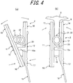
- a height dimension of the plunger side rod portion 4 in the illustrated vertical direction is larger than that of a vertical gap between the inner side surfaces of the pair of pinching portions 13 and 14 in a state where the skin S is nipped. Then, if the plunger side rod portion 4 is inserted into the rod insertion portion 23, the plunger side rod portion 4 comes into contact with the slope 24 of the respective pinching portions 13 and 14.
- the pinching portions 13 and 14 nipping the skin S can be gradually opened. Therefore, the pressure generated in the skin S which is pinched by the pinching portions 13 and 14 is gradually released as the drug is injected. Invasion of the drug due to a pressurized free end of a subcutaneous nerve is reduced. In this manner, a large amount of the drug can be subcutaneously administered.
- the plunger side rod portion 4 can also adopt a configuration in which a tapered distal portion 4a is disposed in the distal end of the plunger side rod portion 4.
- the tapered distal portion 4a has a shape whose sectional area gradually decreases toward the distal side.
- the plunger side rod portion 4 is inserted into the rod insertion portion 23 in the tapered distal portion 4a.
- a gap between the pair of pinching portions 13 and 14 can be gradually widened.
- the plunger side rod portion 4 having the tapered distal portion 4a disposed therein can also be applied to the configuration in which the slope 24 is disposed in the pair of pinching portions 13 and 14.
- a tapered angle of the tapered distal portion 4a is adjusted. In this manner, the gap between the pair of pinching portions 13 and 14 can be gradually widened at the timing and to an extent which is suitable for the injection amount of the drug.
- the syringe 3 is pulled out from the puncture guide portion 22, thereby performing a needle removal process of removing the needle 32 of the syringe 3 from the skin S.
- a pair of nipping portions for opening 16 and 17 are pinched and nipped by two fingers, thereby performing a releasing process of releasing the force of the pair of pinching portions 13 and 14 nipping the skin S.
- the plunger side rod portion 4 gradually weakens the pinching force of the pinching portions 13 and 14 nipping the skin S. Accordingly, it is possible to omit the releasing process of releasing the force of the pair of pinching portions 13 and 14 nipping the skin S. In this manner, the skin S into which the drug is injected by the syringe 3 is released from a state of being nipped by the pinching portions 13 and 14 of the puncture assisting device 2, and the drug is completely administered.
- the skin S of the elbow joint stretching portion at the elbow is stably nipped by the puncture assisting device 2, and the needle 32 of the syringe 3 punctures the skin S nipped by the puncture assisting device 2 from a lateral side.
- the drug can be administered into the skin S. Therefore, the puncture assisting device 2 is operated by using one hand so as to nip the skin S of the elbow joint stretching portion at the elbow in the other arm. Subsequently, the syringe 3 is held by using one hand detached from the puncture assisting device 2.
- the puncture guide portions 21 and 22 are used as a guide, and the needle 32 of the syringe 3 punctures the skin S nipped by the puncture assisting device 2 from a lateral side of the puncture assisting device 2. In this manner, the drug can be easily, safely, and subcutaneously injected into the skin S of the elbow joint stretching portion at the elbow by oneself.
- a puncture device set 101 or a puncture assisting device 102 according to the second embodiment of the present invention which is illustrated in Fig. 9 is used when a drug such as biological products is subcutaneously injected into a skin of an elbow joint stretching portion at an elbow in various treatments for rheumatoid arthritis or multiple sclerosis, for example.
- the puncture device set 101 includes the puncture assisting device 102 and a syringe 103.
- a general syringe which is commercially available can also be used for the independent puncture assisting device 102.
- the puncture assisting device 102 includes a first pinching piece 111 and a second pinching piece 112.
- first pinching piece 111 and the second pinching piece 112 can be made of a synthetic resin such as an acrylic resin or an ABS resin, but can also be formed of other materials such as metal made of stainless steel and an aluminum alloy.
- a pair of leg portions 111a are disposed on a distal side (upper side in Fig. 9 ) of the first pinching piece 111. These leg portions 111a respectively have a shape of being curved outward so as to widen a gap with the second pinching piece 112, and are arranged parallel to each other by leaving a gap therebetween. Similarly, a pair of leg portions 112a are disposed on a distal side (upper side in Fig. 9 ) of the second pinching piece 112. These leg portions 112a respectively have a shape of being curved outward so as to widen a gap with the first pinching piece 111, and are arranged parallel to each other by leaving a gap therebetween.
- the first pinching piece 111 and the second pinching piece 112 have a substantially symmetrical shape, and are combined with each other in an arrangement in which outer shapes thereof are substantially aligned with each other.
- a pair of hinge pieces 111b protruding inward are integrally disposed in the intermediate portion in the longitudinal direction of the inner side surface (surface facing the second pinching piece 112 side) of the first pinching piece 111.
- a pair of hinge pieces 112b protruding inward are integrally disposed in the intermediate portion in the longitudinal direction of the inner side surface (surface facing the first pinching piece 111 side) of the second pinching piece 112.
- the pair of hinge pieces 111b of the first pinching piece 111 are arranged by overlapping each other on the inside of the pair of respectively corresponding hinge pieces 112b of the second pinching piece 112, and are connected so as to be pivotable relative to the hinge pieces 112b by a pin portion (not illustrated). That is, the first pinching piece 111 can pivot relative to the second pinching piece 112 around the center of a pin portion of the hinge pieces 111b and 112b.
- the first pinching piece 111 and the second pinching piece 112 can also adopt a configuration in which both of these are combined with each other so as to be relatively pivotable by using other pivoting mechanisms.
- First pinching portions 113 are respectively disposed in each distal end of the pair of leg portions 111a of the first pinching piece 111.
- Second pinching portions 114 are respectively disposed in each distal end of the pair of leg portions 112a of the second pinching piece 112.
- One of the first pinching portions 113 is arranged facing one of the second pinching portions 114 so that a flat pinching surface 113a thereof faces a flat pinching surface 114a of the second pinching portions 114.
- one of the first pinching portions 113 is arranged facing the other of the second pinching portions 114 so that the flat pinching surface 113a thereof faces the flat pinching surface 114a of the second pinching portions 114.
- the pair of first pinching portions 113 and the pair of second pinching portions 114 can also adopt a configuration in which the first pinching portions 113 and the second pinching portions 114 arranged so as to obliquely face each other are formed in a point-symmetrical shape around the central position of the four pinching portions 113 and 114.
- the pinching surface 113a of the first pinching portion 113 and the pinching surface 114a of the second pinching portion 114 which are arranged so as to obliquely face each other are parallel to and face each other.
- the pinching surfaces 113a and 114a of the other two pinching portions 113 and 114 which are arranged so as to obliquely face each other are parallel to and face each other. According to this configuration, any one of the four pinching surfaces 113a and 114a of the respective pinching portions 113 and 114 faces the central position of the four pinching portions 113 and 114. In this manner, it is possible to more stably nip the skin S.
- the number of the pinching portions 113 and 114 may be at least three. Four or more pinching portions can also be disposed. It is preferable that all of the pinching portions are arranged parallel to each other in an annular shape around the central position, regardless of the number of the pinching portions.
- the pair of pinching portions 113 and the pair of pinching portions 114 can be opened and closed so as to move close to or away from each other by relatively pivoting the first pinching piece 111 and the second pinching piece 112. Then, the first pinching portion 113 and the second pinching portion 114 which are opened and closed can nip the skin S by being closed in a state where the skin S of the elbow joint stretching portion at the elbow is pinched therebetween. In addition, the skin S nipped therebetween can be released by opening the first pinching portion 113 and the second pinching portion 114.
- the first pinching portion 113 and the second pinching portion 114 which are combined with each other so as to be openable and closeable in this way configure the skin collecting portion G for collecting and nipping the skin S.
- the pair of pinching portions 113 disposed in the first pinching piece 111 are connected to each other by an arc-shaped first arc portion 113b which is integrally disposed therebetween.
- the pair of pinching portions 114 disposed in the second pinching piece 112 are connected to each other by an arc-shaped second arc portion 114b which is integrally disposed therebetween.
- These arc portions 113b and 114b are curved in a direction where both of these respectively widen a gap therebetween.
- a pair of C-springs 115 are mounted on the puncture assisting device 102.
- a pair of slit-like through-holes 111c for spring insertion are disposed in the first pinching piece 111.
- a pair of slit-like through-holes 112c for spring insertion are disposed in the second pinching piece 112.
- the pair of C-springs 115 respectively have a shape in which a wire rod made of spring steel or stainless steel is curved in a C-shape, are respectively inserted into the corresponding through-holes 111c and 112c.
- One end thereof is supported by the outer side surface of the first pinching piece 111, and the other end thereof is supported by the outer side surface of the second pinching piece 112.
- the first pinching portion 113 and the second pinching portion 114 are biased by the pair of C-springs 115 in a mutually closing direction, that is, in a direction of moving close to each other.
- the C-spring 115 it is also possible to use a resin-made spring or the like without being limited to the above-described spring steel or stainless steel.
- the biasing portion is not limited to the C-spring 115 having the above-described configuration.
- other configurations using a helical spring, a torsion spring, and an elastic material such as rubber can also be adopted as long as the first pinching portion 113 and the second pinching portion 114 can be biased in the mutually closing direction.
- a portion of the first pinching piece 111 which is located on the proximal side (opposite side to the side having the first pinching portion 113) further from the hinge piece 112b is a first nipping portion for opening 116.
- a portion of the second pinching piece 112 which is located on the proximal side (opposite side to the side having the second pinching portion 114) further from the hinge piece 112b is a second nipping portion for opening 117.
- these nipping portions for opening 116 and 117 are nipped and pinched by two fingers, and are operated in the direction of moving close to each other.
- the pair of pinching portions 113 and 114 can be opened by relatively pivoting the first pinching piece 111 and the second pinching piece 112. If the operation of the nipping portions for opening 116 and 117 is halted, a spring force of the C-spring 115 causes the pair of pinching portions 113 and 114 to return to a closed state. That is, the pair of pinching portions 113 and 114 can be opened and closed by operating these nipping portions for opening 116 and 117.
- the nipping portions for opening 116 and 117 can adopt a configuration in which finger hook portions 116a and 117a are integrally disposed parallel to a side of the nipping portions for opening 116 and 117.
- the finger hook portions 116a and 117a are formed in a plate-like shape in which both of these are slightly warped so as to respectively project inward.
- These finger hook portions 116a and 117a are integrally disposed in the nipping portions for opening 116 and 117. In this manner, fingers are likely to be hooked into the nipping portions for opening 116 and 117. Accordingly, it is possible to improve operability thereof.
- the nipping portions for opening 116 and 117 are nipped and pinched by fingers so as to open the pair of pinching portions 113 and 114.
- the pair of pinching portions 113 and 114 are pushed against the skin S of the elbow joint stretching portion at the elbow in the vertical direction.
- the operation of the nipping portions for opening 116 and 117 is restarted. In this manner, the skin S can be nipped and held between the pair of pinching portions 113 and 114.
- a syringe insertion portion 121 is disposed between the first pinching portions 113 and 114 and the nipping portions for opening 116 and 117.
- the syringe insertion portion 121 is arranged inside the hinge pieces 111b and 112b, and is fixed to either the inner surface of the first pinching piece 111 or the inner side surface of the second pinching piece 112.
- the syringe insertion portion 121 is formed in a cylindrical shape including an insertion hole 121a in the axial center, and the syringe 103 can be inserted into the insertion hole 121a. In addition, the syringe insertion portion 121 can hold the syringe 103 inserted into the insertion hole 121a.
- the syringe insertion portion 121 is disposed by adopting a posture in which the insertion hole 121a is open toward the central position of the four pinching portions 113 and 114, that is, by adopting a posture in which the axial center of the insertion hole 121a passes through the central position of the four pinching portions 113 and 114.
- the syringe 103 inserted into the insertion hole 121a of the syringe insertion portion 121 adopts a posture in which a needle 132 thereof faces the central position of the four pinching portions 113 and 114, that is, a posture in a direction along the central axis of the four pinching portions 113 and 114.
- the central position of the four pinching portions 113 and 114 is the skin collecting portion G. However, in particular, it is most preferable to insert the needle 132 into a central position of a rectangle obtained by linearly connecting each reference position of the four pinching portions 113 and 114 (for example, a center position of the pinching portions 113a and 114a).
- a distal portion of the insertion hole 121a may be obliquely disposed so that the insertion hole 121a faces the central position in a state where the nipping portion for opening 116 is opened.
- the syringe insertion portion 121 can also adopt a configuration in which the syringe insertion portion 121 is disposed integrally with the first pinching piece 111 or the second pinching piece 112.
- the syringe insertion portion 121 can also adopt a configuration in which a pin portion of the hinge penetrates the hinge pieces 111b and 112b and the syringe insertion portion 121, and in which the syringe insertion portion 121 always faces the central position in both states such as a state where the nipping portions for opening 116 and 117 are opened and a state where the nipping portions for opening 116 and 117 are closed.
- a configuration in order to prohibit the syringe insertion portion 121 from rotating around the pin portion of the hinge when the syringe is inserted or when the drug solution is injected, a configuration can also be adopted in which at least two pinching piece and elastic piece in the four pinching portions 113 and 114 hold the syringe insertion portion 121 in a posture of facing the central position.
- the syringe 103 includes a plunger 105, an outer cylinder body 131, and the needle 132.
- the outer diameter of a portion close to the needle 132 of the outer cylinder body 131 of the syringe 103 is slightly smaller than the inner diameter of the insertion hole 121a of the syringe insertion portion 121. Therefore, the syringe 103 can be inserted into the insertion hole 121a of the syringe insertion portion 121.
- a configuration can also be adopted in which a stopper or the like is disposed in the outer cylinder body 131 of the syringe 103 so as to regulate an insertion depth of the syringe insertion portion 121 of the syringe 103 inserted into the insertion hole 121a, that is, a puncture depth of the needle 132 of the syringe 103 puncturing the skin S.
- An annular finger hook flange 131c extending outward in the radial direction is integrally disposed in the opening end of the outer cylinder body 131.
- a disk-shaped thrusting flange 105a is integrally disposed in the proximal end of the plunger 105.
- a forefinger and a middle finger are hooked into the finger hook flange 131c of the outer cylinder body 131, and a thumb is hooked into the thrusting flange 105a of the plunger 105.
- the thumb pushes the plunger 105 toward the inside of the outer cylinder body 131. In this manner, it is possible to easily perform an operation for dispensing a drug accommodated inside the outer cylinder body 131 outward from the needle tip 132a of the needle 132.
- a procedure will be described in a drug administration method (drug solution injection method) in which a drug is subcutaneously injected into the skin S of an elbow joint stretching portion at an elbow by using the puncture device set 101 according to the second embodiment of the present invention.
- a skin nipping process of nipping the skin S of the elbow joint stretching portion at the elbow is performed by using the pair of pinching portions 113 and 114 of the puncture assisting device 102, that is, the skin collecting portion G.
- a pair of nipping portions for opening 116 and 117 and the finger hook portions 116a and 117a are nipped and pinched by fingers, for example, so as to open the pair of pinching portions 113 and 114.
- the pair of pinching portions 113 and 114 are pushed against the skin S of the elbow joint stretching portion at the elbow in the vertical direction so as to release an operation force applied to the nipping portions for opening 116 and 117 and the finger hook portions 116a and 117a.
- the skin S is nipped and held between the pinching portions 113 and 114.
- a spring force is applied to the pair of pinching portions 113 and 114 from the C-spring 115 in a closing direction thereof. Accordingly, the skin S nipped by the pinching portions 113 and 114 is brought into a state of being pressurized between the pinching portions 113 and 114.
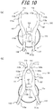
- the skin S is nipped in four directions by the four pinching portions 113 and 114. Accordingly, the skin S in the nipped portion has a substantially columnar shape.
- the pair of first pinching portions 113 are connected to each other by the first arch portion 113b
- the pair of second pinching portions 114 are connected to each other by the second arch portion 114b. Accordingly, a portion of the skin S nipped by the four pinching portions 113 and 114 is pinched between the arch portions 113b and 114b. In this manner, the skin S can be more reliably nipped in a columnar shape. In this way, the skin S nipped by the puncture assisting device 102 in the skin nipping process protrudes from the surface of the elbow in the columnar shape in the vertical direction.
- a collecting process can also be performed in which the skin S of the elbow joint stretching portion at the elbow is collected so that the skin S has a shape which is more likely to be nipped.
- the collecting process can be performed by using a method of nipping the skin S in a wider range, after the skin S is nipped between the pair of pinching portions 113 and 114, the skin S is once detached therefrom, and the pinching portions 113 and 114 are reopened.
- a configuration can also be adopted in which the skin S is more likely to be collected by disposing an adhesive material or an uneven shape, for example, in each distal portion of the pair of pinching portions 113 and the pair of pinching portions 114.
- the collecting process can be performed by using a method in which the skin S is collected by a hand without using the puncture assisting device 102, or in which the skin S is collected by using other devices.
- the syringe 103 is inserted into the insertion hole 121a of the syringe insertion portion 121.
- the syringe 103 is inserted into the insertion hole 121a of the syringe insertion portion 121 in the vertical direction to the skin S of the elbow joint stretching portion at the elbow from a side having the nipping portions for opening 116 and 117 of the puncture assisting device 102. In this manner, the syringe 103 is set in the syringe insertion portion 121.
- the syringe 103 set in the syringe insertion portion 121 is pushed toward a portion among the four pinching portions 113 and 114 along the syringe insertion portion 121, that is, toward the skin S nipped by the pinching portions 113 and 114 so that the needle 132 punctures the skin S in the vertical direction to the skin S nipped in the columnar shape at the central position of the four pinching portions 113 and 114.
- the needle 132 of the syringe 103 punctures the skin S along the central axis passing through the central position of the four pinching portions 113 and 114. Since the needle 132 vertically punctures the skin S, the number of nerves through which the needle 132 passes is reduced. Accordingly, it is possible to relieve pain caused by the puncture.
- Each space is disposed between the respective leg portions 111a and 112a of the pinching pieces 111 and 112.
- the respective leg portions 111a and 112a have a curved shape so as to widen a gap therebetween. Accordingly, when the needle 132 of the syringe 103 punctures the skin S, it is possible to satisfactorily view and recognize progress of the puncture through a portion between the respective leg portions 111a and 112a. In this manner, it is possible to easily carry out puncture work of the needle 132 by using the puncture assisting device 102.
- the plunger 105 of the syringe 103 is pushed toward the needle 132 side so as to inject the drug into the inside of the skin S through the needle 132 of the syringe 103.
- the skin S is nipped in a columnar shape by the puncture assisting device 102, and a space for the injected drug is likely to be subcutaneously formed. Accordingly, it is possible to relieve pain caused by invasive pressure when the drug is injected.
- the syringe 103 is pulled out from the syringe insertion portion 121 of the syringe 103 so as to perform a needle removal process of removing the needle 132 of the syringe 103 from the skin S.
- a pair of nipping portions for opening 116 and 117 and the finger hook portions 116a and 117a are pinched and nipped by fingers, thereby performing a releasing process of releasing the force of the four pinching portions 113 and 114 nipping the skin S.
- the releasing process may be performed before the needle removal process. In this case, during the releasing process or when the puncture assisting device 102 is moved away from the elbow joint stretching portion at the elbow, the needle 132 is naturally removed.
- the skin S of the elbow joint stretching portion at the elbow is stably nipped by the puncture assisting device 102, and the needle 132 of the syringe 103 punctures the skin S nipped by the puncture assisting device 102 in the vertical direction.
- the puncture assisting device 102 is operated by using one hand so as to nip the skin S of the elbow joint stretching portion at the elbow in the other arm.
- the syringe 103 held by using one hand detached from the puncture assisting device 102 is inserted into the insertion hole 121a of the syringe insertion portion 121.
- the needle 132 of the syringe 103 punctures the skin S nipped by the puncture assisting device 102 in the vertical direction. In this manner, the drug can be easily, safely, and subcutaneously injected into the skin S of the elbow joint stretching portion at the elbow by oneself.
- a syringe setting process of setting the syringe 103 in the puncture assisting device 102 is performed.
- the skin S of the elbow joint stretching portion at the elbow is nipped by the four pinching portions 113 and 114, thereby enabling a configuration for performing a puncture process in which the needle 132 of the syringe 103 punctures the nipped skin S.
- the syringe 103 is set in advance at a predetermined position of the syringe insertion portion 121.
- the skin S pinched among the four pinching portions 113 and 114 gradually swells in a columnar shape, thereby allowing the needle 132 to automatically puncture the skin S in a process of being nipped among the four pinching portions 113 and 114. Therefore, the needle 132 of the syringe 103 can easily puncture the skin S through a simple operation, only by setting the syringe 103 in the syringe insertion portion 121 of the puncture assisting device 102 and causing the four pinching portions 113 and 114 to nip the skin S in the vertical direction.
- the needle 132 of the syringe 103 punctures the skin S
- the drug injection process, the releasing process, and the needle removal process are performed.
- the force of the four pinching portions 113 and 114 nipping the skin S is released by performing the releasing process, and the skin S is no longer held in the columnar shape. Accordingly, the needle removal process is performed as the skin S is automatically detached from the needle 132.
- Fig. 15 is a perspective view illustrating a modification example of the puncture assisting device illustrated in Fig. 9 .
- Fig. 16 is a view for describing an arrangement of a syringe insertion portion in the puncture assisting device illustrated in Fig. 15 .
- a configuration can also be adopted in which the syringe insertion portion 121 is arranged outside the hinge pieces 111b and 112b.
- the syringe insertion portion 121 is disposed by adopting a posture in which the insertion hole 121a is open toward the central position of the four pinching portions 113 and 114, that is, by adopting a posture in which the axial center of the insertion hole 121a passes through the central position of the four pinching portions 113 and 114.
- the syringe insertion portion 121 adopts a posture in which the axial direction of the insertion hole 121a is shifted as much as an angle of 25 degrees from an axial center L passing through the central position of the four pinching portions 113 and 114.
- Fig. 17 (a) is a perspective view of a puncture assisting device and a syringe which configure a puncture device set according to the other invention
- Fig. 17 (b) is a side view of the puncture assisting device illustrated in Fig. 17(a)
- Fig. 18(a) is a perspective view illustrating a state where a needle of a syringe punctures a skin nipped by the puncture assisting device illustrated in Fig. 17
- Fig. 18(b) is a sectional view thereof.
- a space forming process of preparing a skin arrangement space 230 is performed in order to arrange the skin S of the elbow joint stretching portion at the elbow in a puncture assisting device 202.
- a thumb is hooked into an end surface 212b of an inner gripping body 212, and the thumb pushes the inner gripping body 212 toward the inside of an outer gripping body 211.
- a forefinger, a middle finger, and a ring finger are hooked into a finger hooking concave portion 215 disposed on a blocking wall 211e of the outer gripping body 211. These fingers push the outer gripping body 211 toward the inner gripping body 212.
- the inner gripping body 212 is moved against a spring 213 so as to reach an opening position with respect to the outer gripping body 211. Accordingly, it is possible to prepare the skin arrangement space 230 to be formed by a first opening portion 218 and a second opening portion 221 overlapping each other in the puncture assisting device 202.
- any finger may be hooked into the blocking wall 211e of the outer gripping body 211 and the end surface 212b of the inner gripping body 212.
- the thumb is hooked into the end surface 212b of the inner gripping body 212
- other fingers are hooked into the blocking wall 211e of the outer gripping body 211.
- a pushing process is performed by pushing the puncture assisting device 202 having the skin arrangement space 230 prepared therein against the skin S of the elbow joint stretching portion at the elbow.
- the side wall 211a of the outer gripping body 211 of the puncture assisting device 202 is pushed against the skin S of the elbow joint stretching portion at the elbow.
- the skin S is arranged inside the first opening portion 218 and the second opening portion 221, that is, inside the skin arrangement space 230.
- the side wall 211a of the outer gripping body 211 is formed as a concave surface which is curved inward. Accordingly, the side wall 211a is fitted to the surface of the elbow joint stretching portion at the elbow. In this manner, the skin S of the elbow joint stretching portion at the elbow can be arranged inside the skin arrangement space 230 as much as possible.
- a skin nipping process is performed in order to nip the skin S arranged in the skin arrangement space 230 between a first pinching portion 219 and a second pinching portion 222.
- the side wall 211a of the outer gripping body 211 of the puncture assisting device 202 is pushed against the skin S of the elbow joint stretching portion at the elbow.
- the fingers are detached from the outer gripping body 211 and the inner gripping body 212. In this manner, the inner gripping body 212 is moved toward the closing position by the spring force of the spring 213.
- the skin S arranged in the skin arrangement space 230 can be nipped between the first pinching portion 219 and the second pinching portion 222 which move in the direction of moving close to each other.
- the nipped skin S is caused to reach a portion having the needle insertion portion 220 of the first pinching portion 219.
- the spring force of the spring 213 is applied to the first pinching portion 219 and the second pinching portion 222 in the direction where both of these are closed. Accordingly, the skin S is held in a state of being nipped between the pinching portions 219 and 222.
- the pinching portions 219 and 222 are respectively disposed in the outer gripping body 211 and the inner gripping body 212 which are combined with each other in this sliding manner, thereby adopting a configuration in which the skin S is nipped between the pinching portions 219 and 222. Accordingly, the skin S can be reliably nipped by performing a simple operation.
- a collecting process can also be performed in which the skin S of the elbow joint stretching portion at the elbow is collected so that the skin S has a shape which is more likely to be arranged inside the skin arrangement space 230 (shape which is more likely to be nipped).
- the collecting process can be performed by using a method of nipping the skin S in a wider range, after the skin S is nipped between the pair of pinching portions 219 and 222, the skin S is once detached therefrom, and the pinching portions 219 and 222 are reopened.
- a configuration can also be adopted in which the skin S is more likely to be collected by disposing an adhesive material or an uneven shape, for example, in each distal portion of the pair of pinching portions 219 and 222.
- the collecting process can be performed by using a method in which the skin S is collected by a hand without using the puncture assisting device 202, or in which the skin S is collected by using other devices.
- a puncture process is performed.
- the puncture process as illustrated in Fig. 18(a) , the syringe 203 is inserted through the syringe insertion portion 223 disposed in the inner gripping body 212.
- an outer peripheral surface of the outer cylinder body 203b comes into sliding contact with the inner surface of the syringe insertion portion 223, thereby causing the syringe insertion portion 223 to regulate the insertion direction of the syringe 203.
- the syringe insertion portion 223 is oriented to a front side of a body.
- the opening end of the syringe insertion portion 223 is formed in a tapered shape by a pair of slopes 223a. Accordingly, it is easy to carry out work for inserting the syringe 203 into the syringe insertion portion 223. If the syringe 203 is inserted into the syringe insertion portion 223, as illustrated in Fig. 18(b) , the needle 203a is inserted into the needle insertion portion 220.
- the needle 203a punctures the skin S of the elbow joint stretching portion at the elbow which is nipped between the first pinching portion 219 and the second pinching portion 222.
- a configuration is adopted in which the outer cylinder body 203b of the syringe 203 is guided to the syringe insertion portion 223, and in which a hub 203e is guided to the needle insertion portion 220.
- the needle 203a of the syringe 203 can easily and accurately puncture a predetermined site of the skin S by carrying out simple work for only inserting the syringe 203 into the syringe insertion portion 223.
- a needle support portion 203d of the syringe 203 comes into contact with the distal end of the needle insertion portion 220, thereby regulating the puncture depth to be a predetermined depth when the needle 203a of the syringe 203 punctures the skin S (puncture depth regulating process). Therefore, it is possible to prevent the needle 203a of the syringe 203 from excessively deeply puncturing the skin S or from penetrating the skin S.
- a drug injection process is performed.
- a plunger 203c of the syringe 203 is pushed toward the needle 203a side, thereby injecting a drug into the inside of the skin S through the needle 203a of the syringe 203.
- a forefinger and a middle finger are hooked into a constricting portion 224 disposed in both side surfaces 212c and 212d of the inner gripping body 212, and a thumb is hooked into the thrusting flange 203g of the plunger 203c.
- the thumb pushes the plunger 203c toward the inside of the outer cylinder body 203b. In this manner, it is possible to easily perform an operation for pushing the plunger 203c, that is, the drug injection process.
- a releasing process is performed in order to release the skin S of the elbow joint stretching portion at the elbow which is nipped between the first pinching portion 219 and the second pinching portion 222.
- the thumb pushes the inner gripping body 212 and the other finger pushes the outer gripping body 211, thereby moving the inner gripping body 212 against the spring 213 so as to reach the opening position.
- the first pinching portion 219 and the second pinching portion 222 are moved in the direction of moving away from each other.
- the first opening portion 218 and the second opening portion 221 are brought into an opened state, thereby releasing the skin S of the elbow joint stretching portion at the elbow which is nipped between the first pinching portion 219 and the second pinching portion 222.
- the needle 203a puncturing the skin S is removed from the skin S.
- the skin S of the elbow joint stretching portion at the elbow is released from the puncture assisting device 202, thereby completing the drug administration.
- a needle removal process may be performed in order to remove the needle 203a of the syringe 203 from the skin S by pulling out the syringe 203 from the syringe insertion portion 223.
- the puncture assisting device 202 can more easily and stably nip the skin S of the elbow joint stretching portion at the elbow.
- the needle 203a of the syringe 203 can easily and accurately puncture the skin S nipped between the pair of pinching portions 219 and 222 of the puncture assisting device 202 by carrying out simple work for only inserting the syringe 203 through the syringe insertion portion 223 disposed in the puncture assisting device 202.
- the puncture assisting device 202 is operated by using one hand so as to nip the skin S of the elbow joint stretching portion at the elbow in the other arm.
- the syringe 203 held by using one hand detached from the puncture assisting device 202 is inserted through the syringe insertion portion 223.
- the needle 203a of the syringe 203 punctures the skin S nipped between the pair of pinching portions 219 and 222.
- the drug can be easily, safely, and subcutaneously injected into the skin S of the elbow joint stretching portion at the elbow, using one hand by oneself.
- the reference numeral 203f represents a flange of the syringe 203
- the reference numerals 211b to 211d represent side walls of the outer gripping body 211
- the reference numeral 212a represents a side surface of the inner gripping body 212
- the reference numeral 212e represents a distal surface of the inner gripping body 212
- the reference numeral 214 represents a combining opening of the outer gripping body 211
- the reference numeral 224a represents a holding surface of the constricting portion 224
- the reference numeral 224b represents a slope of the constricting portion 224.
- the puncture device sets 1, 101, and 201 are used in subcutaneously injecting the drug by nipping the skin S other than an elbow skin.
Landscapes
- Health & Medical Sciences (AREA)
- Vascular Medicine (AREA)
- Engineering & Computer Science (AREA)
- Anesthesiology (AREA)
- Biomedical Technology (AREA)
- Heart & Thoracic Surgery (AREA)
- Hematology (AREA)
- Life Sciences & Earth Sciences (AREA)
- Animal Behavior & Ethology (AREA)
- General Health & Medical Sciences (AREA)
- Public Health (AREA)
- Veterinary Medicine (AREA)
- Dermatology (AREA)
- Infusion, Injection, And Reservoir Apparatuses (AREA)
Abstract
Description
- The present invention relates to a puncture assisting device and a puncture device set which can be used when a drug is subcutaneously injected.
- In the related art, when a drug (drug solution) is subcutaneously injected, a puncture device is used which includes a needle puncturing a skin so as to intracutaneously or subcutaneously inject the drug through the needle (for example, refer to PTL 1).
- When the drug is subcutaneously injected by using this puncture device, as an injection site, an upper arm, an abdomen, a thigh, a hip, and the like are mainly selected, since their regions are wide and are located at an easily visible position. The reason is that the drug is easily administered thereto and the skin is likely to be nipped when the needle of the puncture device punctures the skin.
- However, in most of these sites, the skin cannot stretch so much. In general, it is known that the upper limit of a drug amount which can be administered is 1 ml. In addition, even if the drug amount to be administered is limited, the administered drug invasively pressurizes a free end of a subcutaneous nerve or causes severe pain due to features of the drug (pH or a surfactant). The subcutaneous injection is basically carried out without anesthesia. In addition, in many cases, the drug has to be continuously injected multiple times. Accordingly, pain relief during the injection has been required.
- Therefore, a method has been proposed in which the subcutaneous injection is carried out through the skin of an elbow joint stretching portion at an elbow instead of the above-described sites. The skin of the elbow joint stretching portion at the elbow is more likely to stretch than the skin of other sites, and does not have anatomically major nerves or blood vessels which are present therein. Therefore, a large amount of the drug can be subcutaneously injected without causing pain, compared to other sites.
- PTL 1:
JP-A-2008-295590 - In recent years, drugs such as biological products administered by subcutaneous injection have increased. In addition, it has been observed that a large amount of the drug tends to be administered at one time in order to lengthen the duration of drug effects. In addition, it has also been observed that some drugs are subcutaneously injected by oneself (self-administration) in treating rheumatoid arthritis or multiple sclerosis. Therefore, if the drug can be subcutaneously injected into a skin of an elbow joint stretching portion at an elbow by oneself, the subcutaneous injection leads to improved convenience in that the number of times for outpatient treatment or inpatient treatment is reduced.
- However, the skin of the elbow joint stretching portion at the elbow is a site which cannot be touched by a hand on the same side. Accordingly, it is necessary to carry out the subcutaneous injection using one hand. Consequently, there are difficulties in subcutaneously injecting the drug into the skin of the elbow joint stretching portion at the elbow by oneself.
- The present invention is made in view of the above-described problem, and an object thereof is to provide a puncture assisting device or a puncture assisting device and a puncture device set which enable a drug to be easily and subcutaneously injected into a skin of an elbow joint stretching portion at an elbow by oneself.
- A puncture assisting device according to the present invention has a pair of plate-like pinching portions that face each other, and that are combined with each other so as to be openable and closeable, a biasing portion that biases the pair of pinching portions in a mutually closing direction, a pair of nipping portions for opening that can operate the pair of pinching portions in a mutually opening direction, and a rod insertion portion that is disposed between the pair of pinching portions, and into which a rod portion for widening a gap between the pair of pinching portions is inserted.
- In the above-described configuration of the puncture assisting device according to the present invention, the biasing portion may be a U-shaped plate spring including a first plate-like piece supported by one of the pinching portions, a second plate-like piece supported by the other of the pinching portions, and a curved piece for connecting the first plate-like piece and the second plate-like piece to each other, and it is preferable that the rod insertion portion is disposed between the first plate-like piece and the second plate-like piece.
- In addition, in the above-described configuration of the puncture assisting device according to the present invention, it is preferable that the rod insertion portion has a portion whose sectional area is smaller than a sectional area of the rod portion.
- Furthermore, in the above-described configuration of the puncture assisting device according to the present invention, the rod insertion portion may have a portion whose sectional area gradually decreases toward an inner side from an entrance side, and it is preferable that the gap between the pair of pinching portions is gradually widened as the rod portion is inserted into the rod insertion portion.
- Furthermore, in the above-described configuration of the puncture assisting device according to the present invention, it is preferable that a puncture guide portion into which a needle of a syringe is inserted is disposed in a side portion of at least one of the pinching portions.
- Furthermore, in the above-described configuration of the puncture assisting device according to the present invention, it is preferable that the puncture guide portion is formed in a ring shape including a guide hole having a smaller diameter than an outer diameter of a needle support portion of the syringe.
- The present invention relates to the above-described puncture assisting device and a puncture device set. The puncture device set has the above-described puncture assisting device and a syringe in which the rod portion is disposed in a plunger.
- In the above-described configuration of the puncture device set according to the present invention, the rod portion may be formed in a shape whose sectional area gradually decreases toward a distal end, and it is preferable that a gap between a pair of pinching portions is gradually widened as the rod portion is inserted into the rod insertion portion.
- For example, a drug administration method (drug solution injection method) which can be performed by using the puncture assisting device and the puncture device set according to the present invention is as follows.
- The drug administration method includes a skin nipping process of nipping a skin of an elbow joint stretching portion at an elbow by using a skin collecting portion of the puncture assisting device, a syringe setting process of setting a syringe into a syringe insertion portion of the puncture assisting device which nips the skin of the elbow joint stretching portion at the elbow, a puncture process of causing a needle of the syringe to puncture the skin of the elbow joint stretching portion at the elbow which is nipped by the skin collecting portion, a drug injection process of injecting a drug into the skin of the elbow joint stretching portion at the elbow through the needle by pushing a plunger of the syringe, and a needle removal process of removing the needle of the syringe from the skin of the elbow joint stretching portion at the elbow which is nipped by the skin collecting portion.
- On the assumption of the above-described configuration, the drug administration method further includes a releasing process of releasing a force of the skin collecting portion which nips the skin of the elbow joint stretching portion at the elbow after the needle removal process.
- On the assumption of the above-described configuration, in the drug administration method, the skin collecting portion has a pair of plate-like pinching portions which face each other. In the puncture process, the needle of the syringe punctures the skin from a lateral side of the pinching portion so as to be parallel to the pinching portion between the pair of pinching portions.
- On the assumption of the above-described configuration, in the drug administration method, in the skin nipping process, the skin collecting portion nips the skin of the elbow joint stretching portion at the elbow by adopting a posture in which the pair of pinching portions are orthogonal to a longitudinal direction of an arm.
- On the assumption of the above-described configuration, in the drug administration method, in the drug injection process, a gap between the pair of pinching portions is gradually widened by inserting a rod portion into a rod insertion portion disposed between the pair of pinching portions.
- On the assumption of the above-described configuration, the drug administration method further has a puncture depth regulating process of regulating a depth of the needle of the syringe which punctures the skin.
- On the assumption of the above-described configuration, the drug administration method further has a collecting process of collecting the skin of the elbow joint stretching portion at the elbow before the skin nipping process.
- According to the present invention, a puncture assisting device stably nips a skin of an elbow joint stretching portion at an elbow, and a needle of a syringe punctures the skin nipped by the puncture assisting device, thereby enabling a drug to be subcutaneously administered. Therefore, subcutaneous injection can be easily and safely carried out by oneself.
-
- [
Fig. 1] Fig. 1 is a perspective view of a puncture assisting device and a syringe which configure a puncture device set according to a first embodiment of the present invention. - [
Fig. 2] Fig. 2 (a) is a longitudinal sectional view of the puncture assisting device illustrated inFig. 1 , andFig. 2(b) is a sectional view taken along line A-A inFig. 2(a) . - [
Fig. 3] Fig. 3 is a perspective view of a plunger of the syringe illustrated inFig. 1 . - [
Fig. 4] Fig. 4 is a view illustrating a procedure in which the puncture assisting device illustrated inFig. 1 nips a skin of an elbow joint stretching portion at an elbow.Fig. 4(a) illustrates a state before the skin is nipped, andFig. 4(b) illustrates a state after the skin is nipped. - [
Fig. 5] Fig. 5 is a view illustrating a procedure in which a needle of the syringe punctures the skin nipped by the puncture assisting device.Fig. 5(a) illustrates a state where the syringe is set in a puncture guide portion, andFig. 5(b) illustrates a state where the needle of the syringe punctures the skin. - [
Fig. 6] Fig. 6 is a view illustrating a state where a drug solution is injected into the skin by pushing the plunger of the syringe. - [
Fig. 7] Fig. 7 is a sectional view illustrating a state where a rod portion is inserted into a rod insertion portion and a pair of pinching portions are pushed to open.Fig. 7 (a) illustrates a state before the rod portion is inserted into the rod insertion portion, andFig. 7(b) illustrates a state after the rod portion is inserted into the rod insertion portion. - [
Fig. 8] Fig. 8 is a perspective view illustrating a modification example of the rod portion illustrated inFig. 3 . - [
Fig. 9] Fig. 9 is a perspective view of a puncture assisting device according to a second embodiment of the present invention, and the puncture assisting device and a syringe which configure a puncture device set. - [
Fig. 10] Fig. 10 is a view illustrating a procedure in which the puncture assisting device illustrated inFig. 9 nips a skin of an elbow joint stretching portion at an elbow.Fig. 10(a) illustrates a state before the skin is nipped, andFig. 10(b) illustrates a state after the skin is nipped. - [
Fig. 11] Fig. 11(a) is a sectional view illustrating in detail a state of the skin of the elbow joint stretching portion at the elbow which is nipped by pinching portions, andFig. 11(b) is a sectional view taken along line B-B inFig. 11(a) . - [
Fig. 12] Fig. 12 is a view illustrating a procedure in which a needle of a syringe punctures the skin nipped by the puncture assisting device.Fig. 12 (a) illustrates a state where the syringe is set in a syringe insertion portion, andFig. 12 (b) illustrates a state where the needle of the syringe punctures the skin. - [
Fig. 13] Fig. 13 is a view illustrating a state where a drug solution is injected into the skin by pushing a plunger of the syringe. - [
Fig. 14] Fig. 14 is a view for describing another procedure of a drug administration method using the puncture assisting device illustrated inFig. 9 .Fig. 14(a) illustrates a state before the skin is nipped, andFig. 14(b) illustrates a state after the skin is nipped. - [
Fig. 15] Fig. 15 is a perspective view illustrating a modification example of the puncture assisting device illustrated inFig. 9 . - [
Fig. 16] Fig. 16 is a view for describing an arrangement of a syringe insertion portion in the puncture assisting device illustrated inFig. 15 . - [
Fig. 17] Fig. 17 (a) is a perspective view of a puncture assisting device and a syringe which configure a puncture device set according to the other invention, andFig. 17(b) is a side view of the puncture assisting device illustrated inFig. 17(a) . - [
Fig. 18] Fig. 18 (a) is a perspective view illustrating a state where a needle of a syringe punctures a skin nipped by the puncture assisting device illustrated inFig. 17 , andFig. 18(b) is a sectional view thereof. - Hereinafter, a first embodiment according to the present invention will be described as an example with reference to
Figs. 1 to 8 . - A puncture device set 1 according to the first embodiment of the present invention which is illustrated in
Fig. 1 is used when a drug such as biological products is subcutaneously injected into a skin of an elbow joint stretching portion at an elbow in various treatments for rheumatoid arthritis or multiple sclerosis, for example. The puncture device set 1 has apuncture assisting device 2 and asyringe 3. In thesyringe 3, a plungerside rod portion 4 corresponding to thepuncture assisting device 2 is disposed in aplunger 5. - As illustrated in
Figs. 1 and2 , thepuncture assisting device 2 includes afirst pinching piece 11 and asecond pinching piece 12. Thefirst pinching piece 11 and thesecond pinching piece 12 are respectively configured as a rectangular plate body, and are combined with each other in a thickness direction, in an arrangement where outer shapes thereof are substantially aligned with each other. Aprojection piece portion 12a which extends straight in a width direction thereof and which protrudes toward an inner side surface (surface facing thesecond pinching piece 12 side) of thefirst pinching piece 11 is integrally disposed in an intermediate portion in the longitudinal direction of an inner side surface (surface facing thefirst pinching piece 11 side) of thesecond pinching piece 12. The inner side surface of thefirst pinching piece 11 is in contact with an upper surface of theprojection piece portion 12a. The upper surface of theprojection piece portion 12a is curved in an arc shape when viewed from a lateral side of the pinchingpieces first pinching piece 11 can pivot relative to thesecond pinching piece 12 by using the upper surface of theprojection piece portion 12a as a fulcrum. - For example, the
first pinching piece 11 and thesecond pinching piece 12 can be made of a synthetic resin such as an acrylic resin or an ABS resin, but can also be formed of other materials such as metal made of stainless steel and an aluminum alloy. - In addition, without being limited to a configuration in which the
first pinching piece 11 and thesecond pinching piece 12 are supported by the above-describedprojection piece portion 12a and are combined with each other so as to be relatively pivotable, it is also possible to adopt a configuration in which thefirst pinching piece 11 and thesecond pinching piece 12 are combined with each other so as to be relatively pivotable by using other pivoting mechanisms such as a hinge (joint), for example. - A portion of the
first pinching piece 11 on a distal side (upper side inFigs. 1 and2 ) further from the portion in contact with theprojection piece portion 12a is a plate-likefirst pinching portion 13. A portion of thesecond pinching piece 12 on the distal side further from theprojection piece portion 12a is a plate-likesecond pinching portion 14 which faces thefirst pinching portion 13. The pair of these pinchingportions first pinching piece 11 and thesecond pinching piece 12. Then, thefirst pinching portion 13 and thesecond pinching portion 14 which are opened and closed can nip the skin by being closed in a state where the skin of the elbow joint stretching portion at the elbow is pinched therebetween. In addition, the skin nipped therebetween can be released by opening thefirst pinching portion 13 and thesecond pinching portion 14. The respective inner side surfaces of the pinchingportions grooves first pinching portion 13 and thesecond pinching portion 14 configure a skin collecting portion G. - A
plate spring 15 functioning as a biasing portion is mounted on thepuncture assisting device 2. Thefirst pinching portion 13 and thesecond pinching portion 14 are biased by theplate spring 15 in a mutually closing direction, that is, in a direction of moving close to each other, thereby being brought into contact with each other in a natural state. Thefirst pinching portion 13 and thesecond pinching portion 14 can also adopt a configuration of moving away from each other by leaving a regulated gap therebetween in a natural state. - More specifically, as illustrated in
Fig. 2 , theplate spring 15 is formed in a U-shape in which a first plate-like piece 15a and a second plate-like piece 15b are connected to each other by acurved piece 15c.Concave portions first pinching piece 11 and thesecond pinching piece 12. The first plate-like piece 15a of theplate spring 15 is arranged in theconcave portion 11a disposed in thefirst pinching piece 11, and is supported by thefirst pinching portion 13. The second plate-like piece 15b of theplate spring 15 is arranged in theconcave portion 12b disposed in thesecond pinching piece 12, and is supported by thesecond pinching portion 14. Through-holes pieces concave portions curved piece 15c of theplate spring 15 connects the first plate-like piece 15a and the second plate-like piece 15b to each other via the through-holes columnar locking portions 15d are respectively and integrally disposed in a distal end of the first plate-like piece 15a and the second plate-like piece 15b. The lockingportions 15d engage with lockinggrooves concave portions first pinching piece 11 and thesecond pinching piece 12 of theplate spring 15 and holding a combined state between thefirst pinching piece 11 and thesecond pinching piece 12. - For example, as the
plate spring 15, a metal-made plate spring formed using a steel plate made of spring steel or stainless steel can be used, but for example, a resin-made plate spring can also be used. In addition, the biasing portion is not limited to theplate spring 15 having the above-described configuration. For example, other configurations using a helical spring, a torsion spring, and an elastic material such as rubber can also be adopted as long as thefirst pinching portion 13 and thesecond pinching portion 14 can be biased in the mutually closing direction. - A portion of the
first pinching piece 11 which is located on the proximal side (opposite side to a side having the first pinching portion 13) further from the portion coming into contact with theprojection piece portion 12a is a first nipping portion for opening 16. A portion of thesecond pinching piece 12 which is located on the proximal side (opposite side to a side having the second pinching portion 14) further from theprojection piece portion 12a is a second nipping portion for opening 17. In a state where thefirst pinching portion 13 and thesecond pinching portion 14 are closed, the first nipping portion for opening 16 and the second nipping portion for opening 17 face each other by leaving a gap therebetween. For example, these nipping portions for opening 16 and 17 are nipped and pinched by two fingers, and are operated in the direction of moving close to each other. In this manner, the pair of pinchingportions first pinching piece 11 and thesecond pinching piece 12. If the operation of the nipping portions for opening 16 and 17 is halted, a spring force of theplate spring 15 causes the pair of pinchingportions portions ribs - According to the configuration of the
puncture assisting device 2 having a clip shape in this way, the nipping portions for opening 16 and 17 are nipped and pinched by two fingers so as to open the pair of pinchingportions portions portions - A holding
piece 18 extending in the longitudinal direction is integrally disposed on a proximal end of thesecond pinching piece 12. The holdingpiece 18 is formed in a plate-like shape which is thinner than that of thesecond pinching piece 12, and is slightly inclined toward the outer side surface of thesecond pinching piece 12. In a state where the skin is nipped between the pair of pinchingportions piece 18 is pulled, thereby enabling tension to be applied to the skin nipped by the pinchingportions piece 18 can adopt a configuration for preventing slip, such as acircular hole 18a and a rib as illustrated. - A first puncture guide portion (syringe insertion portion) 21 is disposed in a side portion of the
first pinching portion 13. A second puncture guide portion (syringe insertion portion) 22 is disposed in a side portion of thesecond pinching portion 14. Thepuncture guide portions circular guide holes syringe 3 can be inserted into the guide holes 21a and 22a. Theguide hole 21a of the firstpuncture guide portion 21 adopts a posture facing between thefirst pinching portion 13 and thesecond pinching portion 14, and is integrally disposed in the side portion of thefirst pinching portion 13. Theguide hole 22a of the secondpuncture guide portion 22 adopts a posture facing between thefirst pinching portion 13 and thesecond pinching portion 14, and is integrally disposed in the side portion of thesecond pinching portion 14. Axial centers of the guide holes 21a and 22a of the twopuncture guide portions portions - A
rod insertion portion 23 is disposed between thefirst pinching portion 13 and thesecond pinching portion 14. In the present embodiment, therod insertion portion 23 is disposed between the first plate-like piece 15a and the second plate-like piece 15b of theplate spring 15, which is a region pinched between theprojection piece portion 12a and thepuncture guide portions first pinching portion 13 and thesecond pinching portion 14, and is open toward a side of thefirst pinching portion 13 and thesecond pinching portion 14. As illustrated inFig. 2(b) , a portion between the inner side surface and the side surface of thefirst pinching piece 11 and a portion between the inner side surface and the side surface of thesecond pinching piece 12 are respectively chamfered slopes 24. In this manner, in therod insertion portion 23, a sectional area in an entrance (opening end) thereof is larger than a sectional area of the plungerside rod portion 4 disposed in theplunger 5 of thesyringe 3. The sectional area gradually decreases from the entrance side toward the inner portion side. The central portion is formed in a shape having a fixed sectional area which is smaller than the sectional area of the plungerside rod portion 4. In addition, in a state where thefirst pinching portion 13 and thesecond pinching portion 14 are closed, a gap between the inner side surface of thefirst pinching portion 13 and the inner side surface of thesecond pinching portion 14 in the central portion having the fixed sectional area of therod insertion portion 23 has a width dimension which is smaller than that of the plungerside rod portion 4 to be inserted into therod insertion portion 23. Therefore, if the plungerside rod portion 4 is inserted into therod insertion portion 23, in response to the insertion, a gap between the pair of pinchingportions side rod portion 4. - As illustrated in
Fig. 1 , thesyringe 3 includes anouter cylinder body 31 and aneedle 32 in addition to the plungerside rod portion 4 and theplunger 5 which function as the above-described rod portion. - The
outer cylinder body 31 is formed in a cylindrical shape in which one end is opened and the other end is closed by aneedle support portion 31a, and internally has an accommodation chamber for accommodating a drug. Theplunger 5 is formed in a columnar shape having the diameter corresponding to the inner diameter of theouter cylinder body 31, is inserted into theouter cylinder body 31 from the opening end of theouter cylinder body 31, and is mounted on theouter cylinder body 31 so as to be relatively movable in the axial direction. For example, theouter cylinder body 31 or theplunger 5 can be made of a resin or glass. In addition, theplunger 5 can also adopt a configuration in which a sealing member formed of an elastic body such as rubber and sealing a portion between theplunger 5 and an inner peripheral surface of theouter cylinder body 31 is mounted on the distal end of theplunger 5. - A
cylindrical hub 31b having a smaller diameter than aneedle support portion 31a is integrally disposed in the axial center of theneedle support portion 31a, and theneedle 32 is fixed to thehub 31b. Theneedle 32 is a hollow needle, and aneedle tip 32a thereof is obliquely cut, and is formed so as to have an acute angle. In addition, a proximal portion of theneedle 32 is fixed to thehub 31b, and a lumen thereof communicates with the inside of theouter cylinder body 31 via thehub 31b. As theneedle 32, for example, those which are formed of a metal material such as stainless steel, an aluminum alloy, a titanium alloy, and the like can be used. - The outer diameter of the
needle support portion 31a of thesyringe 3, that is, the outer diameter of theouter cylinder body 31 is larger than the inner diameter of the guide holes 21a and 22a of thepuncture guide portions hub 31b of thesyringe 3 is smaller than the inner diameter of the guide holes 21a and 22a of thepuncture guide portions needle 32 and thehub 31b of thesyringe 3 can be inserted into the guide holes 21a and 22a of thepuncture guide portions puncture assisting device 2. In addition, theneedle support portion 31a comes into contact with thepuncture guide portions needle 32 and thehub 31b are inserted into thepuncture guide portions portions - A pair of
finger hook flanges 31c extending outward in a radial direction thereof is symmetrically arranged, and is integrally disposed in the opening end of theouter cylinder body 31. On the other hand, a disc-shaped thrustingflange 5a is integrally disposed in the proximal end of theplunger 5. In this manner, a forefinger and a middle finger are hooked into the pair offinger hook flanges 31c of theouter cylinder body 31, and a thumb is hooked into the thrustingflange 5a of theplunger 5. The thumb pushes theplunger 5 toward the inside of theouter cylinder body 31. In this manner, it is possible to easily perform an operation for dispensing a drug accommodated inside theouter cylinder body 31 outward from theneedle tip 32a of theneedle 32. - As illustrated in
Fig. 3 , the plungerside rod portion 4 is disposed in theplunger 5. More specifically, the plungerside rod portion 4 is formed in a rod shape which is longer than theplunger 5 and which has a rectangular cross section, and a proximal end thereof is integrally connected to a lower surface of the thrustingflange 5a of theplunger 5. In addition, the plungerside rod portion 4 is arranged on the outside in the radial direction of theplunger 5 by leaving a gap from theplunger 5, and is arranged parallel to theplunger 5 so as to extend along the axial direction of theplunger 5. A distal end of the plungerside rod portion 4 can employ an acute angular shape by means of chamfering. - As in the present embodiment, in a case where the plunger
side rod portion 4 is integrally disposed in theplunger 5, it is preferable to form both of these through injection molding by using a resin material. Without being limited to a configuration of being integrally disposed in theplunger 5, for example, the plungerside rod portion 4 may also adopt a configuration of being fixed to theplunger 5 by using a fastening member, an adhesive, or the like, or by means of fitting and the like. - In addition, the rod portion is not limited to the plunger
side rod portion 4 disposed integrally with theplunger 5 of thesyringe 3, and can also adopt a configuration in which the rod portion is independently disposed separate from theplunger 5. In this case, the rod portion can be independently operated separate from theplunger 5. - A tunnel-shaped
rod support portion 33 extending in the axial direction from a portion of theneedle support portion 31a is integrally disposed at a position where the outer peripheral surface of theouter cylinder body 31 is shifted from the pair offinger hook flanges 31c as much as an angle of 90 degrees. The plungerside rod portion 4 is inserted into the inside of therod support portion 33. An inner surface of therod support portion 33 comes into sliding contact with an outer surface of the plungerside rod portion 4, thereby supporting the plungerside rod portion 4 so as to be slidable. - According to this configuration, if the
plunger 5 is pushed to the inside of theouter cylinder body 31, that is, toward theneedle 32 side, in order to dispense a drug outward from theneedle tip 32a of theneedle 32, the plungerside rod portion 4 gradually protrudes parallel to theneedle 32 from the distal side of theouter cylinder body 31, in response to the pushedplunger 5. - Next, referring to
Figs. 4 to 7 , a procedure will be described in a drug administration method (drug solution injection method) in which a drug is subcutaneously injected into a skin S of an elbow joint stretching portion at an elbow by using the puncture device set 1 according to the first embodiment of the present invention. - First, a skin nipping process of nipping the skin S of the elbow joint stretching portion at the elbow is performed by using the pair of pinching
portions puncture assisting device 2, that is, the skin collecting portion G. As illustrated inFig. 4(a) , in the skin nipping process, a pair of nipping portions for opening 16 and 17 are nipped and pinched by two fingers, for example, so as to open the pair of pinchingportions piece 18. When the pair of pinchingportions portions - Next, in this state, the pair of pinching
portions Fig. 4(b) , the skin S is nipped and held between the pinchingportions puncture guide portions portions portions plate spring 15 in the direction for closing both of these. Accordingly, the skin S nipped by the pinchingportions portions - In the skin nipping process, it is preferable to nip the skin S by adopting a posture in which the pair of pinching
portions portions puncture assisting device 2 nips the skin S by adopting this posture. In this manner, at least any one of thepuncture guide portions puncture guide portions syringe 3 so as to face a side of the stretched arm, and thesyringe 3 can easily puncture the skin S (to be described later). - In order to nip the skin S as much as possible between the pair of pinching
portions portions portions portions - Without being limited to the above-described method, the collecting process can be performed by using a method in which the skin S is collected by a hand without using the
puncture assisting device 2, or in which the skin S is collected by using other devices. - After the skin S is nipped by the pair of pinching
portions piece 18 is pulled, if necessary. In this manner, tension can be applied to the skin S nipped by the pinchingportions - If the skin S is nipped by the
puncture assisting device 2, next, as a syringe setting process, thesyringe 3 is set in any one of thepuncture guide portions Fig. 5 (a) , in the syringe setting process, theneedle 32 of thesyringe 3 is inserted into theguide hole 22a of thepuncture guide portion 22 from a lateral side of thepuncture assisting device 2. In this manner, thesyringe 3 is set in thepuncture guide portion 22. At this time, thesyringe 3 adopts a posture in which the distal end of the plungerside rod portion 4 faces the opening end of therod insertion portion 23. In this way, thesyringe 3 is set in thepuncture guide portions syringe 3 can be easily and accurately set in thepuncture assisting device 2. - Next, as illustrated in
Fig. 5 (b) , as a puncture process, thesyringe 3 set in thepuncture guide portion 22 is pushed toward a portion between the pair of pinchingportions portions needle 32 of thesyringe 3 punctures the skin S. Therefore, theneedle 32 punctures the skin S in parallel to the pinchingportions portions portions portions - At this time, the inner diameter of the
guide hole 22a of thepuncture guide portion 22 is smaller than the outer diameter of theneedle support portion 31a of thesyringe 3. Accordingly, an insertion amount obtained by thesyringe 3 inserted into thepuncture guide portion 22 is regulated within a predetermined range in such a way that theneedle support portion 31a comes into contact with thepuncture guide portion 22. This regulates a puncture depth when theneedle 32 punctures the skin S (puncture depth regulating process). Therefore, it is possible to prevent theneedle 32 from excessively puncturing the skin S or penetrating the skin S after thesyringe 3 is inadvertently and deeply inserted into thepuncture guide portion 22. - If the
needle 32 of thesyringe 3 punctures the skin S, next, as a drug injection process, as illustrated inFig. 6 , theplunger 5 of thesyringe 3 is pushed toward theneedle 32 side so as to inject the drug into the inside of the skin S through theneedle 32 of thesyringe 3. - If the
plunger 5 is pushed toward theneedle 32 side in the drug injection process, theplunger 5 and the plungerside rod portion 4 protrude from therod support portion 33, and are inserted into therod insertion portion 23. As illustrated inFig. 7 (a) , a height dimension of the plungerside rod portion 4 in the illustrated vertical direction is larger than that of a vertical gap between the inner side surfaces of the pair of pinchingportions side rod portion 4 is inserted into therod insertion portion 23, the plungerside rod portion 4 comes into contact with theslope 24 of therespective pinching portions side rod portion 4 is inserted into therod insertion portion 23, a gap between the pair of pinchingportions side rod portion 4. Then, as illustrated inFig. 7(b) , if the plungerside rod portion 4 reaches the intermediate portion of therod insertion portion 23 and is brought into a state of being pinched between the inner side surfaces of therespective pinching portions portions portions - According to this configuration, while the drug is injected into the skin S stably nipped between the pair of pinching
portions puncture assisting device 2 through theneedle 32 of thesyringe 3, the pinchingportions portions - As illustrated in
Fig. 8 , the plungerside rod portion 4 can also adopt a configuration in which a tapereddistal portion 4a is disposed in the distal end of the plungerside rod portion 4. The tapereddistal portion 4a has a shape whose sectional area gradually decreases toward the distal side. In this case, without disposing theslope 24 in the pair of pinchingportions side rod portion 4 is inserted into therod insertion portion 23 in the tapereddistal portion 4a. In this manner, a gap between the pair of pinchingportions side rod portion 4 having the tapereddistal portion 4a disposed therein can also be applied to the configuration in which theslope 24 is disposed in the pair of pinchingportions distal portion 4a is adjusted. In this manner, the gap between the pair of pinchingportions - If the drug is completely injected into the inside of the skin S by pushing the
plunger 5 to reach a regulated position, thesyringe 3 is pulled out from thepuncture guide portion 22, thereby performing a needle removal process of removing theneedle 32 of thesyringe 3 from the skin S. - Then, after the needle removal process, a pair of nipping portions for opening 16 and 17 are pinched and nipped by two fingers, thereby performing a releasing process of releasing the force of the pair of pinching
portions portions puncture assisting device 2 through theneedle 32 of thesyringe 3, the plungerside rod portion 4 gradually weakens the pinching force of the pinchingportions portions syringe 3 is released from a state of being nipped by the pinchingportions puncture assisting device 2, and the drug is completely administered. - In this way, according to the above-described first embodiment of the present invention, the skin S of the elbow joint stretching portion at the elbow is stably nipped by the
puncture assisting device 2, and theneedle 32 of thesyringe 3 punctures the skin S nipped by thepuncture assisting device 2 from a lateral side. In this manner, the drug can be administered into the skin S. Therefore, thepuncture assisting device 2 is operated by using one hand so as to nip the skin S of the elbow joint stretching portion at the elbow in the other arm. Subsequently, thesyringe 3 is held by using one hand detached from thepuncture assisting device 2. Thepuncture guide portions needle 32 of thesyringe 3 punctures the skin S nipped by thepuncture assisting device 2 from a lateral side of thepuncture assisting device 2. In this manner, the drug can be easily, safely, and subcutaneously injected into the skin S of the elbow joint stretching portion at the elbow by oneself. - In addition, it is possible to subcutaneously inject the drug into the skin S of the elbow joint stretching portion at the elbow by oneself. Accordingly, compared to a case where the drug is subcutaneously injected into other sites, a large amount of the drug can be administered without causing pain. In addition, a major nerve is not present in the skin S of the elbow joint stretching portion at the elbow. Accordingly, the
needle 32 of thesyringe 3 can safely puncture the skin S without giving damage to a nerve. - Next, a second embodiment according to the present invention will be described as an example with reference to
Figs. 9 to 16 . - A puncture device set 101 or a
puncture assisting device 102 according to the second embodiment of the present invention which is illustrated inFig. 9 is used when a drug such as biological products is subcutaneously injected into a skin of an elbow joint stretching portion at an elbow in various treatments for rheumatoid arthritis or multiple sclerosis, for example. The puncture device set 101 includes thepuncture assisting device 102 and asyringe 103. As the syringe used for the subcutaneous injection, a general syringe which is commercially available can also be used for the independentpuncture assisting device 102. - The
puncture assisting device 102 includes afirst pinching piece 111 and asecond pinching piece 112. - For example, the
first pinching piece 111 and thesecond pinching piece 112 can be made of a synthetic resin such as an acrylic resin or an ABS resin, but can also be formed of other materials such as metal made of stainless steel and an aluminum alloy. - A pair of
leg portions 111a are disposed on a distal side (upper side inFig. 9 ) of thefirst pinching piece 111. Theseleg portions 111a respectively have a shape of being curved outward so as to widen a gap with thesecond pinching piece 112, and are arranged parallel to each other by leaving a gap therebetween. Similarly, a pair ofleg portions 112a are disposed on a distal side (upper side inFig. 9 ) of thesecond pinching piece 112. Theseleg portions 112a respectively have a shape of being curved outward so as to widen a gap with thefirst pinching piece 111, and are arranged parallel to each other by leaving a gap therebetween. - The
first pinching piece 111 and thesecond pinching piece 112 have a substantially symmetrical shape, and are combined with each other in an arrangement in which outer shapes thereof are substantially aligned with each other. - A pair of
hinge pieces 111b protruding inward are integrally disposed in the intermediate portion in the longitudinal direction of the inner side surface (surface facing thesecond pinching piece 112 side) of thefirst pinching piece 111. A pair ofhinge pieces 112b protruding inward are integrally disposed in the intermediate portion in the longitudinal direction of the inner side surface (surface facing thefirst pinching piece 111 side) of thesecond pinching piece 112. The pair ofhinge pieces 111b of thefirst pinching piece 111 are arranged by overlapping each other on the inside of the pair of respectively correspondinghinge pieces 112b of thesecond pinching piece 112, and are connected so as to be pivotable relative to thehinge pieces 112b by a pin portion (not illustrated). That is, thefirst pinching piece 111 can pivot relative to thesecond pinching piece 112 around the center of a pin portion of thehinge pieces - Without being limited to a configuration in which both of these are combined with each other so as to be relatively pivotable by the above-described
hinge pieces first pinching piece 111 and thesecond pinching piece 112 can also adopt a configuration in which both of these are combined with each other so as to be relatively pivotable by using other pivoting mechanisms. - First pinching
portions 113 are respectively disposed in each distal end of the pair ofleg portions 111a of thefirst pinching piece 111. Second pinchingportions 114 are respectively disposed in each distal end of the pair ofleg portions 112a of thesecond pinching piece 112. One of thefirst pinching portions 113 is arranged facing one of thesecond pinching portions 114 so that aflat pinching surface 113a thereof faces aflat pinching surface 114a of thesecond pinching portions 114. Similarly, one of thefirst pinching portions 113 is arranged facing the other of thesecond pinching portions 114 so that theflat pinching surface 113a thereof faces theflat pinching surface 114a of thesecond pinching portions 114. - Without being limited to the above-described arrangement, for example, the pair of
first pinching portions 113 and the pair ofsecond pinching portions 114 can also adopt a configuration in which thefirst pinching portions 113 and thesecond pinching portions 114 arranged so as to obliquely face each other are formed in a point-symmetrical shape around the central position of the four pinchingportions surface 113a of thefirst pinching portion 113 and the pinchingsurface 114a of thesecond pinching portion 114 which are arranged so as to obliquely face each other are parallel to and face each other. The pinching surfaces 113a and 114a of the other two pinchingportions surfaces respective pinching portions portions - In addition, the number of the pinching
portions - The pair of pinching
portions 113 and the pair of pinchingportions 114 can be opened and closed so as to move close to or away from each other by relatively pivoting thefirst pinching piece 111 and thesecond pinching piece 112. Then, thefirst pinching portion 113 and thesecond pinching portion 114 which are opened and closed can nip the skin S by being closed in a state where the skin S of the elbow joint stretching portion at the elbow is pinched therebetween. In addition, the skin S nipped therebetween can be released by opening thefirst pinching portion 113 and thesecond pinching portion 114. Thefirst pinching portion 113 and thesecond pinching portion 114 which are combined with each other so as to be openable and closeable in this way configure the skin collecting portion G for collecting and nipping the skin S. - The pair of pinching
portions 113 disposed in thefirst pinching piece 111 are connected to each other by an arc-shapedfirst arc portion 113b which is integrally disposed therebetween. Similarly, the pair of pinchingportions 114 disposed in thesecond pinching piece 112 are connected to each other by an arc-shapedsecond arc portion 114b which is integrally disposed therebetween. Thesearc portions - As the biasing portion, a pair of C-
springs 115 are mounted on thepuncture assisting device 102. A pair of slit-like through-holes 111c for spring insertion are disposed in thefirst pinching piece 111. Similarly, a pair of slit-like through-holes 112c for spring insertion are disposed in thesecond pinching piece 112. The pair of C-springs 115 respectively have a shape in which a wire rod made of spring steel or stainless steel is curved in a C-shape, are respectively inserted into the corresponding through-holes first pinching piece 111, and the other end thereof is supported by the outer side surface of thesecond pinching piece 112. In this manner, thefirst pinching portion 113 and thesecond pinching portion 114 are biased by the pair of C-springs 115 in a mutually closing direction, that is, in a direction of moving close to each other. - As the C-
spring 115, it is also possible to use a resin-made spring or the like without being limited to the above-described spring steel or stainless steel. In addition, the biasing portion is not limited to the C-spring 115 having the above-described configuration. For example, other configurations using a helical spring, a torsion spring, and an elastic material such as rubber can also be adopted as long as thefirst pinching portion 113 and thesecond pinching portion 114 can be biased in the mutually closing direction. - A portion of the
first pinching piece 111 which is located on the proximal side (opposite side to the side having the first pinching portion 113) further from thehinge piece 112b is a first nipping portion foropening 116. A portion of thesecond pinching piece 112 which is located on the proximal side (opposite side to the side having the second pinching portion 114) further from thehinge piece 112b is a second nipping portion foropening 117. In a state where thefirst pinching portion 113 and thesecond pinching portion 114 are closed, the first nipping portion for opening 116 and the second nipping portion for opening 117 face each other by leaving a gap therebetween. For example, these nipping portions for opening 116 and 117 are nipped and pinched by two fingers, and are operated in the direction of moving close to each other. In this manner, the pair of pinchingportions first pinching piece 111 and thesecond pinching piece 112. If the operation of the nipping portions for opening 116 and 117 is halted, a spring force of the C-spring 115 causes the pair of pinchingportions portions - The nipping portions for opening 116 and 117 can adopt a configuration in which
finger hook portions finger hook portions finger hook portions - According to the configuration of the
puncture assisting device 102 having a clip shape in this way, the nipping portions for opening 116 and 117 are nipped and pinched by fingers so as to open the pair of pinchingportions portions portions - A
syringe insertion portion 121 is disposed between thefirst pinching portions syringe insertion portion 121 is arranged inside thehinge pieces first pinching piece 111 or the inner side surface of thesecond pinching piece 112. - The
syringe insertion portion 121 is formed in a cylindrical shape including aninsertion hole 121a in the axial center, and thesyringe 103 can be inserted into theinsertion hole 121a. In addition, thesyringe insertion portion 121 can hold thesyringe 103 inserted into theinsertion hole 121a. Thesyringe insertion portion 121 is disposed by adopting a posture in which theinsertion hole 121a is open toward the central position of the four pinchingportions insertion hole 121a passes through the central position of the four pinchingportions syringe 103 inserted into theinsertion hole 121a of thesyringe insertion portion 121 adopts a posture in which aneedle 132 thereof faces the central position of the four pinchingportions portions - The central position of the four pinching
portions needle 132 into a central position of a rectangle obtained by linearly connecting each reference position of the four pinchingportions 113 and 114 (for example, a center position of the pinchingportions - In the
syringe insertion portion 121, a distal portion of theinsertion hole 121a may be obliquely disposed so that theinsertion hole 121a faces the central position in a state where the nipping portion for opening 116 is opened. In addition, thesyringe insertion portion 121 can also adopt a configuration in which thesyringe insertion portion 121 is disposed integrally with thefirst pinching piece 111 or thesecond pinching piece 112. Furthermore, thesyringe insertion portion 121 can also adopt a configuration in which a pin portion of the hinge penetrates thehinge pieces syringe insertion portion 121, and in which thesyringe insertion portion 121 always faces the central position in both states such as a state where the nipping portions for opening 116 and 117 are opened and a state where the nipping portions for opening 116 and 117 are closed. In this case, in order to prohibit thesyringe insertion portion 121 from rotating around the pin portion of the hinge when the syringe is inserted or when the drug solution is injected, a configuration can also be adopted in which at least two pinching piece and elastic piece in the four pinchingportions syringe insertion portion 121 in a posture of facing the central position. - As illustrated in
Fig. 9 , thesyringe 103 includes aplunger 105, anouter cylinder body 131, and theneedle 132. - The outer diameter of a portion close to the
needle 132 of theouter cylinder body 131 of thesyringe 103 is slightly smaller than the inner diameter of theinsertion hole 121a of thesyringe insertion portion 121. Therefore, thesyringe 103 can be inserted into theinsertion hole 121a of thesyringe insertion portion 121. A configuration can also be adopted in which a stopper or the like is disposed in theouter cylinder body 131 of thesyringe 103 so as to regulate an insertion depth of thesyringe insertion portion 121 of thesyringe 103 inserted into theinsertion hole 121a, that is, a puncture depth of theneedle 132 of thesyringe 103 puncturing the skin S. - An annular
finger hook flange 131c extending outward in the radial direction is integrally disposed in the opening end of theouter cylinder body 131. On the other hand, a disk-shaped thrustingflange 105a is integrally disposed in the proximal end of theplunger 105. In this manner, a forefinger and a middle finger are hooked into thefinger hook flange 131c of theouter cylinder body 131, and a thumb is hooked into the thrustingflange 105a of theplunger 105. The thumb pushes theplunger 105 toward the inside of theouter cylinder body 131. In this manner, it is possible to easily perform an operation for dispensing a drug accommodated inside theouter cylinder body 131 outward from theneedle tip 132a of theneedle 132. - Next, referring to
Figs. 10 to 14 , a procedure will be described in a drug administration method (drug solution injection method) in which a drug is subcutaneously injected into the skin S of an elbow joint stretching portion at an elbow by using the puncture device set 101 according to the second embodiment of the present invention. - First, a skin nipping process of nipping the skin S of the elbow joint stretching portion at the elbow is performed by using the pair of pinching
portions puncture assisting device 102, that is, the skin collecting portion G. As illustrated inFig. 10(a) , in the skin nipping process, a pair of nipping portions for opening 116 and 117 and thefinger hook portions portions - Next, in this state, the pair of pinching
portions finger hook portions Fig. 10(b) , the skin S is nipped and held between the pinchingportions portions spring 115 in a closing direction thereof. Accordingly, the skin S nipped by the pinchingportions portions - At this time, as illustrated in
Fig. 11 , the skin S is nipped in four directions by the four pinchingportions first pinching portions 113 are connected to each other by the firstarch portion 113b, and the pair ofsecond pinching portions 114 are connected to each other by the secondarch portion 114b. Accordingly, a portion of the skin S nipped by the four pinchingportions arch portions puncture assisting device 102 in the skin nipping process protrudes from the surface of the elbow in the columnar shape in the vertical direction. - In order to nip the skin S as much as possible between the pair of pinching
portions portions portions portions 113 and the pair of pinchingportions 114. - Without being limited to the above-described method, the collecting process can be performed by using a method in which the skin S is collected by a hand without using the
puncture assisting device 102, or in which the skin S is collected by using other devices. - If the skin S is nipped by the
puncture assisting device 102, next, as a syringe setting process, thesyringe 103 is inserted into theinsertion hole 121a of thesyringe insertion portion 121. As illustrated inFig. 12(a) , in the syringe setting process, thesyringe 103 is inserted into theinsertion hole 121a of thesyringe insertion portion 121 in the vertical direction to the skin S of the elbow joint stretching portion at the elbow from a side having the nipping portions for opening 116 and 117 of thepuncture assisting device 102. In this manner, thesyringe 103 is set in thesyringe insertion portion 121. - Next, as illustrated in
Fig. 12 (b) , as a puncture process, thesyringe 103 set in thesyringe insertion portion 121 is pushed toward a portion among the four pinchingportions syringe insertion portion 121, that is, toward the skin S nipped by the pinchingportions needle 132 punctures the skin S in the vertical direction to the skin S nipped in the columnar shape at the central position of the four pinchingportions needle 132 of thesyringe 103 punctures the skin S along the central axis passing through the central position of the four pinchingportions needle 132 vertically punctures the skin S, the number of nerves through which theneedle 132 passes is reduced. Accordingly, it is possible to relieve pain caused by the puncture. - Each space is disposed between the
respective leg portions pieces respective leg portions needle 132 of thesyringe 103 punctures the skin S, it is possible to satisfactorily view and recognize progress of the puncture through a portion between therespective leg portions needle 132 by using thepuncture assisting device 102. - In a case of adopting a configuration in which a stopper or the like is disposed in the
outer cylinder body 131 of thesyringe 103 so as to regulate an insertion depth of thesyringe 103 inserted into theinsertion hole 121a of thesyringe insertion portion 121, it is possible to regulate a puncture depth of theneedle 132 of thesyringe 103 puncturing the skin S(puncture depth regulating process). Therefore, it is possible to prevent theneedle 132 of thesyringe 103 from excessively deeply puncturing the skin S. - If the
needle 132 of thesyringe 103 punctures the skin S, next, as a drug injection process, as illustrated inFig. 13 , theplunger 105 of thesyringe 103 is pushed toward theneedle 132 side so as to inject the drug into the inside of the skin S through theneedle 132 of thesyringe 103. At this time, the skin S is nipped in a columnar shape by thepuncture assisting device 102, and a space for the injected drug is likely to be subcutaneously formed. Accordingly, it is possible to relieve pain caused by invasive pressure when the drug is injected. - If the drug is completely injected in the inside of the skin S after the
plunger 105 is pushed to reach a regulated position, thesyringe 103 is pulled out from thesyringe insertion portion 121 of thesyringe 103 so as to perform a needle removal process of removing theneedle 132 of thesyringe 103 from the skin S. - Then, after the needle removal process, a pair of nipping portions for opening 116 and 117 and the
finger hook portions portions syringe 103 is released from a state of being nipped by the pinchingportions puncture assisting device 102. The releasing process may be performed before the needle removal process. In this case, during the releasing process or when thepuncture assisting device 102 is moved away from the elbow joint stretching portion at the elbow, theneedle 132 is naturally removed. - In this way, according to the above-described second embodiment of the present invention, the skin S of the elbow joint stretching portion at the elbow is stably nipped by the
puncture assisting device 102, and theneedle 132 of thesyringe 103 punctures the skin S nipped by thepuncture assisting device 102 in the vertical direction. In this manner, the drug can be administered into the skin S. Therefore, thepuncture assisting device 102 is operated by using one hand so as to nip the skin S of the elbow joint stretching portion at the elbow in the other arm. Subsequently, thesyringe 103 held by using one hand detached from thepuncture assisting device 102 is inserted into theinsertion hole 121a of thesyringe insertion portion 121. Theneedle 132 of thesyringe 103 punctures the skin S nipped by thepuncture assisting device 102 in the vertical direction. In this manner, the drug can be easily, safely, and subcutaneously injected into the skin S of the elbow joint stretching portion at the elbow by oneself. - In addition, it is possible to subcutaneously inject the drug into the skin S of the elbow joint stretching portion at the elbow by oneself. Accordingly, compared to a case where the drug is subcutaneously injected into other sites, a large amount of the drug can be administered without causing pain. In addition, a major nerve is not present in the skin S of the elbow joint stretching portion at the elbow. Accordingly, the
needle 132 of thesyringe 103 can safely puncture the skin S without giving damage to a nerve. - As illustrated in
Fig. 14 , in the drug administration method using thepuncture assisting device 102 according to the present embodiment, as illustrated inFig. 14(a) , first, a syringe setting process of setting thesyringe 103 in thepuncture assisting device 102 is performed. Thereafter, as illustrated inFig. 14(b) , the skin S of the elbow joint stretching portion at the elbow is nipped by the four pinchingportions needle 132 of thesyringe 103 punctures the nipped skin S. In this case, thesyringe 103 is set in advance at a predetermined position of thesyringe insertion portion 121. Accordingly, the skin S pinched among the four pinchingportions needle 132 to automatically puncture the skin S in a process of being nipped among the four pinchingportions needle 132 of thesyringe 103 can easily puncture the skin S through a simple operation, only by setting thesyringe 103 in thesyringe insertion portion 121 of thepuncture assisting device 102 and causing the four pinchingportions - Even in this case, after the
needle 132 of thesyringe 103 punctures the skin S, the drug injection process, the releasing process, and the needle removal process are performed. However, the force of the four pinchingportions needle 132. -
Fig. 15 is a perspective view illustrating a modification example of the puncture assisting device illustrated inFig. 9 .Fig. 16 is a view for describing an arrangement of a syringe insertion portion in the puncture assisting device illustrated inFig. 15 . - As illustrated in
Figs. 15 and16 , without being limited to a configuration in which thesyringe insertion portion 121 is arranged inside thehinge pieces syringe insertion portion 121 is arranged outside thehinge pieces syringe insertion portion 121 is disposed by adopting a posture in which theinsertion hole 121a is open toward the central position of the four pinchingportions insertion hole 121a passes through the central position of the four pinchingportions syringe insertion portion 121 adopts a posture in which the axial direction of theinsertion hole 121a is shifted as much as an angle of 25 degrees from an axial center L passing through the central position of the four pinchingportions first pinching portion 113 and thesecond pinching portion 114 are parallel to each other along the longitudinal direction of the stretched arm. In this manner, it is possible to easily carry out work for inserting thesyringe 103 into thesyringe insertion portion 121 in such a way that the insertion direction of thesyringe 103 with respect to thepuncture assisting device 102 is tilted toward the inner side of a body. -
Fig. 17 (a) is a perspective view of a puncture assisting device and a syringe which configure a puncture device set according to the other invention, andFig. 17 (b) is a side view of the puncture assisting device illustrated inFig. 17(a) . In addition,Fig. 18(a) is a perspective view illustrating a state where a needle of a syringe punctures a skin nipped by the puncture assisting device illustrated inFig. 17 , andFig. 18(b) is a sectional view thereof. Hereinafter, using a puncture device set 201 illustrated inFig. 17 will be described. - First, a space forming process of preparing a
skin arrangement space 230 is performed in order to arrange the skin S of the elbow joint stretching portion at the elbow in apuncture assisting device 202. In the space forming process, a thumb is hooked into anend surface 212b of an innergripping body 212, and the thumb pushes the innergripping body 212 toward the inside of an outergripping body 211. A forefinger, a middle finger, and a ring finger are hooked into a finger hookingconcave portion 215 disposed on ablocking wall 211e of the outergripping body 211. These fingers push the outergripping body 211 toward the innergripping body 212. In this manner, the innergripping body 212 is moved against aspring 213 so as to reach an opening position with respect to the outergripping body 211. Accordingly, it is possible to prepare theskin arrangement space 230 to be formed by afirst opening portion 218 and asecond opening portion 221 overlapping each other in thepuncture assisting device 202. - In the space forming process, any finger may be hooked into the blocking
wall 211e of the outergripping body 211 and theend surface 212b of the innergripping body 212. However, the thumb is hooked into theend surface 212b of the innergripping body 212, and other fingers are hooked into the blockingwall 211e of the outergripping body 211. In this manner, when thepuncture assisting device 202 is caused to face the skin S of the elbow joint stretching portion at the elbow, thesyringe insertion portion 223 can be directed to a front side of a body. - Next, in a state where an arm is stretched straight, a pushing process is performed by pushing the
puncture assisting device 202 having theskin arrangement space 230 prepared therein against the skin S of the elbow joint stretching portion at the elbow. In the pushing process, theside wall 211a of the outergripping body 211 of thepuncture assisting device 202 is pushed against the skin S of the elbow joint stretching portion at the elbow. The skin S is arranged inside thefirst opening portion 218 and thesecond opening portion 221, that is, inside theskin arrangement space 230. At this time, theside wall 211a of the outergripping body 211 is formed as a concave surface which is curved inward. Accordingly, theside wall 211a is fitted to the surface of the elbow joint stretching portion at the elbow. In this manner, the skin S of the elbow joint stretching portion at the elbow can be arranged inside theskin arrangement space 230 as much as possible. - Next, a skin nipping process is performed in order to nip the skin S arranged in the
skin arrangement space 230 between afirst pinching portion 219 and asecond pinching portion 222. In the skin nipping process, theside wall 211a of the outergripping body 211 of thepuncture assisting device 202 is pushed against the skin S of the elbow joint stretching portion at the elbow. In a state where the skin S is arranged in theskin arrangement space 230, the fingers are detached from the outergripping body 211 and the innergripping body 212. In this manner, the innergripping body 212 is moved toward the closing position by the spring force of thespring 213. In this manner, the skin S arranged in theskin arrangement space 230 can be nipped between thefirst pinching portion 219 and thesecond pinching portion 222 which move in the direction of moving close to each other. At this time, the nipped skin S is caused to reach a portion having theneedle insertion portion 220 of thefirst pinching portion 219. The spring force of thespring 213 is applied to thefirst pinching portion 219 and thesecond pinching portion 222 in the direction where both of these are closed. Accordingly, the skin S is held in a state of being nipped between the pinchingportions - The pinching
portions gripping body 211 and the innergripping body 212 which are combined with each other in this sliding manner, thereby adopting a configuration in which the skin S is nipped between the pinchingportions - In order to enable the skin S to be reliably nipped as much as possible in the skin nipping process by arranging the skin S as much as possible inside the
skin arrangement space 230, before the skin nipping process, a collecting process can also be performed in which the skin S of the elbow joint stretching portion at the elbow is collected so that the skin S has a shape which is more likely to be arranged inside the skin arrangement space 230 (shape which is more likely to be nipped). For example, through the same work as that in the skin nipping process, the collecting process can be performed by using a method of nipping the skin S in a wider range, after the skin S is nipped between the pair of pinchingportions portions portions - Without being limited to the above-described method, the collecting process can be performed by using a method in which the skin S is collected by a hand without using the
puncture assisting device 202, or in which the skin S is collected by using other devices. - If the skin S is nipped between the pair of pinching
portions puncture assisting device 202, next, a puncture process is performed. In the puncture process, as illustrated inFig. 18(a) , thesyringe 203 is inserted through thesyringe insertion portion 223 disposed in the innergripping body 212. In thesyringe 203, an outer peripheral surface of theouter cylinder body 203b comes into sliding contact with the inner surface of thesyringe insertion portion 223, thereby causing thesyringe insertion portion 223 to regulate the insertion direction of thesyringe 203. At this time, thesyringe insertion portion 223 is oriented to a front side of a body. In addition, the opening end of thesyringe insertion portion 223 is formed in a tapered shape by a pair ofslopes 223a. Accordingly, it is easy to carry out work for inserting thesyringe 203 into thesyringe insertion portion 223. If thesyringe 203 is inserted into thesyringe insertion portion 223, as illustrated inFig. 18(b) , theneedle 203a is inserted into theneedle insertion portion 220. From a lateral side thereof, theneedle 203a punctures the skin S of the elbow joint stretching portion at the elbow which is nipped between thefirst pinching portion 219 and thesecond pinching portion 222. In this way, a configuration is adopted in which theouter cylinder body 203b of thesyringe 203 is guided to thesyringe insertion portion 223, and in which ahub 203e is guided to theneedle insertion portion 220. Accordingly, theneedle 203a of thesyringe 203 can easily and accurately puncture a predetermined site of the skin S by carrying out simple work for only inserting thesyringe 203 into thesyringe insertion portion 223. - In the puncture process, a
needle support portion 203d of thesyringe 203 comes into contact with the distal end of theneedle insertion portion 220, thereby regulating the puncture depth to be a predetermined depth when theneedle 203a of thesyringe 203 punctures the skin S (puncture depth regulating process). Therefore, it is possible to prevent theneedle 203a of thesyringe 203 from excessively deeply puncturing the skin S or from penetrating the skin S. - If the
needle 203a of thesyringe 203 punctures the skin S, next, a drug injection process is performed. In the drug injection process, aplunger 203c of thesyringe 203 is pushed toward theneedle 203a side, thereby injecting a drug into the inside of the skin S through theneedle 203a of thesyringe 203. At this time, a forefinger and a middle finger are hooked into a constrictingportion 224 disposed in both side surfaces 212c and 212d of the innergripping body 212, and a thumb is hooked into the thrustingflange 203g of theplunger 203c. The thumb pushes theplunger 203c toward the inside of theouter cylinder body 203b. In this manner, it is possible to easily perform an operation for pushing theplunger 203c, that is, the drug injection process. - Then, a releasing process is performed in order to release the skin S of the elbow joint stretching portion at the elbow which is nipped between the
first pinching portion 219 and thesecond pinching portion 222. In the releasing process, similarly to the space forming process, the thumb pushes the innergripping body 212 and the other finger pushes the outergripping body 211, thereby moving the innergripping body 212 against thespring 213 so as to reach the opening position. In this manner, thefirst pinching portion 219 and thesecond pinching portion 222 are moved in the direction of moving away from each other. Thefirst opening portion 218 and thesecond opening portion 221 are brought into an opened state, thereby releasing the skin S of the elbow joint stretching portion at the elbow which is nipped between thefirst pinching portion 219 and thesecond pinching portion 222. In addition, as the skin S is released, theneedle 203a puncturing the skin S is removed from the skin S. Then, the skin S of the elbow joint stretching portion at the elbow is released from thepuncture assisting device 202, thereby completing the drug administration. - After the
plunger 203c is pushed to reach a regulated position and the drug is completely injected into the inside of the skin S, a needle removal process may be performed in order to remove theneedle 203a of thesyringe 203 from the skin S by pulling out thesyringe 203 from thesyringe insertion portion 223. - In this way, according to the present invention, the
puncture assisting device 202 can more easily and stably nip the skin S of the elbow joint stretching portion at the elbow. Theneedle 203a of thesyringe 203 can easily and accurately puncture the skin S nipped between the pair of pinchingportions puncture assisting device 202 by carrying out simple work for only inserting thesyringe 203 through thesyringe insertion portion 223 disposed in thepuncture assisting device 202. In this manner, the drug can be easily administered into the skin S. Therefore, thepuncture assisting device 202 is operated by using one hand so as to nip the skin S of the elbow joint stretching portion at the elbow in the other arm. Subsequently, thesyringe 203 held by using one hand detached from thepuncture assisting device 202 is inserted through thesyringe insertion portion 223. Through this simple work, theneedle 203a of thesyringe 203 punctures the skin S nipped between the pair of pinchingportions - Referring to
Figs. 17 and18 , thereference numeral 203f represents a flange of thesyringe 203, thereference numerals 211b to 211d represent side walls of the outergripping body 211, thereference numeral 212a represents a side surface of the innergripping body 212, thereference numeral 212e represents a distal surface of the innergripping body 212, thereference numeral 214 represents a combining opening of the outergripping body 211, thereference numeral 224a represents a holding surface of the constrictingportion 224, and thereference numeral 224b represents a slope of the constrictingportion 224. - Without being limited to the above-described embodiments, the present invention can be modified in various ways within the scope not departing from the gist of the present invention, as a matter of course.
- For example, in the present embodiment, a case has been described in which the puncture device sets 1, 101, and 201 are used in subcutaneously injecting the drug by nipping the skin S other than an elbow skin. However, it is also possible to use the puncture device sets 1 and 101 according to the present embodiment, when the drug is subcutaneously injected to other body sites.
-
- 1
- PUNCTURE DEVICE SET
- 2
- PUNCTURE ASSISTING DEVICE
- 3
- SYRINGE
- 4
- PLUNGER SIDE ROD PORTION
- 4a
- TAPERED DISTAL PORTION
- 5
- PLUNGER
- 5a
- THRUSTING FLANGE
- 11
- FIRST PINCHING PIECE
- 11a
- CONCAVE PORTION
- 11b
- THROUGH-HOLE
- 11c
- LOCKING GROOVE
- 12
- SECOND PINCHING PIECE
- 12a
- CONVEX PIECE PORTION
- 12b
- CONCAVE PORTION
- 12c
- THROUGH-HOLE
- 12d
- LOCKING GROOVE
- 13
- FIRST PINCHING PORTION
- 13a
- GROOVE
- 14
- SECOND PINCHING PORTION
- 14a
- GROOVE
- 15
- PLATE SPRING (BIASING PORTION)
- 15a
- FIRST PLATE-LIKE PIECE
- 15b
- SECOND PLATE-LIKE PIECE
- 15c
- CURVED PIECE
- 15d
- LOCKING PORTION
- 16
- FIRST NIPPING PORTION FOR OPENING
- 16a
- RIB
- 17
- SECOND NIPPING PORTION FOR OPENING
- 17a
- RIB
- 18
- HOLDING PIECE
- 18a
- HOLE
- 21
- FIRST PUNCTURE GUIDE PORTION
- 21a
- GUIDE HOLE
- 22
- SECOND PUNCTURE GUIDE PORTION
- 22a
- GUIDE HOLE
- 23
- ROD INSERTION PORTION
- 24
- SLOPE
- 31
- OUTER CYLINDER BODY
- 31a
- NEEDLE SUPPORT PORTION
- 31b
- HUB
- 31c
- FINGER HOOK FLANGE
- 32
- NEEDLE
- 32a
- NEEDLE TIP
- 33
- ROD SUPPORT PORTION
- 101
- PUNCTURE DEVICE SET
- 102
- PUNCTURE ASSISTING DEVICE
- 103
- SYRINGE
- 105
- PLUNGER
- 105a
- THRUSTING FLANGE
- 111
- FIRST PINCHING PIECE
- 111a
- LEG PORTION
- 111b
- HINGE PIECE
- 111c
- THROUGH-HOLE
- 112
- SECOND PINCHING PIECE
- 112a
- LEG PORTION
- 112b
- HINGE PIECE
- 112c
- THROUGH-HOLE
- 113
- FIRST PINCHING PORTION
- 113a
- PINCHING SURFACE
- 113b
- FIRST ARCH PORTION
- 114
- SECOND PINCHING PORTION
- 114a
- PINCHING SURFACE
- 114b
- SECOND ARCH PORTION
- 115
- C-SPRING
- 116
- FIRST NIPPING PORTION FOR OPENING
- 116a
- FINGER HOOK PORTION
- 117
- SECOND NIPPING PORTION FOR OPENING
- 117a
- FINGER HOOK PORTION
- 121
- SYRINGE INSERTION PORTION
- 121a
- INSERTION HOLE
- 131
- OUTER CYLINDER BODY
- 131c
- FINGER HOOK FLANGE
- 132
- NEEDLE
- 132a
- NEEDLE TIP
- 201
- PUNCTURE DEVICE SET
- 202
- PUNCTURE ASSISTING DEVICE
- 203
- SYRINGE
- 203a
- NEEDLE
- 203b
- OUTER CYLINDER BODY
- 203c
- PLUNGER
- 203d
- NEEDLE SUPPORT PORTION
- 203e
- HUB
- 203f
- LOCKING FLANGE
- 203g
- THRUSTING FLANGE
- 211
- OUTER GRIPPING BODY
- 211a to 211d
- SIDE WALL
- 211e
- BLOCKING WALL
- 212
- INNER GRIPPING BODY
- 212a,212c,212d
- SIDE SURFACE
- 212b
- END SURFACE
- 212e
- DISTAL SURFACE
- 213
- SPRING
- 214
- COMBINING OPENING
- 215
- CONCAVE PORTION
- 218
- FIRST OPENING PORTION
- 219
- FIRST PINCHING PORTION
- 220
- NEEDLE INSERTION PORTION
- 221
- SECOND OPENING PORTION
- 222
- SECOND PINCHING PORTION
- 223
- SYRINGE INSERTION PORTION
- 223a
- SLOPE
- 224
- CONSTRICTING PORTION
- 224a
- HOLDING SURFACE
- 224b
- SLOPE
- 230
- SKIN ARRANGEMENT SPACE
- S
- SKIN
- G
- SKIN COLLECTING PORTION
Claims (8)
- A puncture assisting device comprising:a pair of plate-like pinching portions that face each other, and that are combined with each other so as to be openable and closeable;a biasing portion that biases the pair of pinching portions in a mutually closing direction;a pair of nipping portions for opening that can operate the pair of pinching portions in a mutually opening direction; anda rod insertion portion that is disposed between the pair of pinching portions, and into which a rod portion for widening a gap between the pair of pinching portions is inserted.
- The puncture assisting device according to Claim 1,
wherein the biasing portion is a U-shaped plate spring including a first plate-like piece supported by one of the pinching portions, a second plate-like piece supported by the other of the pinching portions, and a curved piece for connecting the first plate-like piece and the second plate-like piece to each other, and
wherein the rod insertion portion is disposed between the first plate-like piece and the second plate-like piece. - The puncture assisting device according to Claim 1 or 2,
wherein the rod insertion portion has a portion whose sectional area is smaller than a sectional area of the rod portion. - The puncture assisting device according to Claim 3,
wherein the rod insertion portion has a portion whose sectional area gradually decreases toward an inner side from an entrance side, and
wherein the gap between the pair of pinching portions is gradually widened as the rod portion is inserted into the rod insertion portion. - The puncture assisting device according to any one of Claims 1 to 4,
wherein a puncture guide portion into which a needle of a syringe is inserted is disposed in a side portion of at least one of the pinching portions. - The puncture assisting device according to Claim 5,
wherein the puncture guide portion is formed in a ring shape including a guide hole having a smaller diameter than an outer diameter of a needle support portion of the syringe. - A puncture device set comprising:the puncture assisting device according to any one of Claims 1 to 6; anda syringe in which the rod portion is disposed in a plunger.
- The puncture device set according to Claim 7,
wherein the rod portion is formed in a shape whose sectional area gradually decreases toward a distal end, and
wherein a gap between a pair of pinching portions is gradually widened as the rod portion is inserted into the rod insertion portion.
Applications Claiming Priority (2)
| Application Number | Priority Date | Filing Date | Title |
|---|---|---|---|
| JP2014017831 | 2014-01-31 | ||
| PCT/JP2015/000431 WO2015115113A1 (en) | 2014-01-31 | 2015-01-30 | Puncture aid and puncture instrument set |
Publications (2)
| Publication Number | Publication Date |
|---|---|
| EP3100756A1 true EP3100756A1 (en) | 2016-12-07 |
| EP3100756A4 EP3100756A4 (en) | 2017-10-11 |
Family
ID=53756692
Family Applications (1)
| Application Number | Title | Priority Date | Filing Date |
|---|---|---|---|
| EP15742569.5A Withdrawn EP3100756A4 (en) | 2014-01-31 | 2015-01-30 | Puncture aid and puncture instrument set |
Country Status (4)
| Country | Link |
|---|---|
| US (1) | US10238815B2 (en) |
| EP (1) | EP3100756A4 (en) |
| JP (1) | JP6404837B2 (en) |
| WO (1) | WO2015115113A1 (en) |
Cited By (4)
| Publication number | Priority date | Publication date | Assignee | Title |
|---|---|---|---|---|
| GB2567848A (en) * | 2017-10-26 | 2019-05-01 | Ndm Technologies Ltd | Injection device |
| KR20220000510A (en) * | 2020-06-26 | 2022-01-04 | 방훈섭 | A guide tool for intravenous injection |
| CN114768006A (en) * | 2022-05-12 | 2022-07-22 | 中国人民解放军总医院第六医学中心 | Multi-point positioning equipment for anesthetic injector based on environmental resistance |
| WO2022165248A1 (en) * | 2021-01-29 | 2022-08-04 | Invaio Sciences International Gmbh | Plant injection systems and uses thereof |
Families Citing this family (16)
| Publication number | Priority date | Publication date | Assignee | Title |
|---|---|---|---|---|
| US10099916B2 (en) | 2014-02-28 | 2018-10-16 | Beyond Twenty Ltd. | Electronic vaporiser system |
| GB2544499A (en) * | 2015-11-18 | 2017-05-24 | Tickletec Ltd | Injector pen safety aid |
| US10179008B2 (en) * | 2016-04-19 | 2019-01-15 | Lsi Solutions, Inc. | Needle assembly for pleural space insufflation and methods thereof |
| JP7004180B2 (en) | 2016-07-15 | 2022-01-21 | 凸版印刷株式会社 | Lancing device for microneedles |
| CN108904930A (en) * | 2018-07-11 | 2018-11-30 | 江苏省肿瘤医院 | A kind of transfusion port sting device can be used for Needle localization |
| EP3866892A4 (en) * | 2018-10-16 | 2022-07-20 | Koglo Ltd. | System and method for substance delivery |
| US11471615B2 (en) * | 2018-12-15 | 2022-10-18 | Christina McDaniels | Device for assisting subcutaneous injections |
| US20210085893A1 (en) * | 2019-09-25 | 2021-03-25 | Danielle T. Abramson | Device and methodology for preparing skin for self-injection |
| KR102102316B1 (en) * | 2019-12-03 | 2020-04-20 | 오성준 | Syringe holder |
| KR102360191B1 (en) * | 2019-12-23 | 2022-02-08 | 인하대학교 산학협력단 | Automatic injection device for neck and shoulder muscles |
| EP4302807A4 (en) * | 2021-03-01 | 2024-09-04 | Daicel Corporation | DEVICES FOR USE ON A NEEDLELESS SYRINGE, NEEDLELESS SYRINGE WITH DEVICES AND INTRADERMAL INJECTION PROCEDURE |
| US20240335622A1 (en) * | 2021-08-02 | 2024-10-10 | Becton, Dickinson And Company | Support device for medication delivery device |
| EP4448056A1 (en) * | 2021-12-15 | 2024-10-23 | Sanofi | Drug delivery arrangement comprising a skin pinching mechanism |
| KR102684326B1 (en) * | 2022-03-22 | 2024-07-10 | 인제대학교 산학협력단 | Skin layer automatic injection device |
| EP4529939A1 (en) * | 2023-09-28 | 2025-04-02 | Heraeus Medical GmbH | Injector positioning device, injection device and method |
| CN117695481B (en) * | 2024-02-05 | 2024-05-14 | 四川省医学科学院·四川省人民医院 | Auxiliary device for subcutaneous injection |
Family Cites Families (8)
| Publication number | Priority date | Publication date | Assignee | Title |
|---|---|---|---|---|
| US3324854A (en) * | 1964-04-23 | 1967-06-13 | Harry Swartz | Apparatus for facilitating the insertion of a hypodermic syringe needle |
| US3814080A (en) * | 1972-11-13 | 1974-06-04 | Becton Dickinson Co | Vessel cannulator and clamp for lymphangiography |
| US4223673A (en) * | 1978-10-11 | 1980-09-23 | Harris William J | Device for puckering the flesh to assist in injections |
| US5147306A (en) * | 1991-07-01 | 1992-09-15 | Gubich Stephen J | Device for puckering the flesh to facilitate injections |
| WO2007047813A2 (en) * | 2005-10-19 | 2007-04-26 | Ams Research Corporation | Needle delivery system for electrodes |
| JP2008295590A (en) * | 2007-05-29 | 2008-12-11 | Terumo Corp | Puncture instrument |
| AU2010204445B2 (en) * | 2009-01-07 | 2015-09-03 | 2405871 Ontario Inc. | Treatment of soft tissue injury using hyaluronic acid and botulinum toxin |
| WO2013104414A1 (en) * | 2012-01-10 | 2013-07-18 | Sanofi-Aventis Deutschland Gmbh | Guiding assembly for intradermal injection |
-
2015
- 2015-01-30 WO PCT/JP2015/000431 patent/WO2015115113A1/en not_active Ceased
- 2015-01-30 EP EP15742569.5A patent/EP3100756A4/en not_active Withdrawn
- 2015-01-30 JP JP2015559831A patent/JP6404837B2/en active Active
-
2016
- 2016-07-29 US US15/223,625 patent/US10238815B2/en active Active
Cited By (6)
| Publication number | Priority date | Publication date | Assignee | Title |
|---|---|---|---|---|
| GB2567848A (en) * | 2017-10-26 | 2019-05-01 | Ndm Technologies Ltd | Injection device |
| GB2567848B (en) * | 2017-10-26 | 2020-05-27 | Ndm Technologies Ltd | Injection device |
| US11738157B2 (en) | 2017-10-26 | 2023-08-29 | Ndm Technologies Limited | Injection device |
| KR20220000510A (en) * | 2020-06-26 | 2022-01-04 | 방훈섭 | A guide tool for intravenous injection |
| WO2022165248A1 (en) * | 2021-01-29 | 2022-08-04 | Invaio Sciences International Gmbh | Plant injection systems and uses thereof |
| CN114768006A (en) * | 2022-05-12 | 2022-07-22 | 中国人民解放军总医院第六医学中心 | Multi-point positioning equipment for anesthetic injector based on environmental resistance |
Also Published As
| Publication number | Publication date |
|---|---|
| US10238815B2 (en) | 2019-03-26 |
| JP6404837B2 (en) | 2018-10-17 |
| WO2015115113A1 (en) | 2015-08-06 |
| US20160331910A1 (en) | 2016-11-17 |
| JPWO2015115113A1 (en) | 2017-03-23 |
| EP3100756A4 (en) | 2017-10-11 |
Similar Documents
| Publication | Publication Date | Title |
|---|---|---|
| US10238815B2 (en) | Puncture assisting device and puncture device set | |
| JP5669730B2 (en) | Device for deflecting the needle safely | |
| RU2650199C1 (en) | Cannula for implantation of filaments | |
| US5460612A (en) | Vascular access port stabilizing tool | |
| KR101391659B1 (en) | Medical thread and apparatus for inserting medical thread | |
| KR101439228B1 (en) | Precision filler injection apparatus for preventing side effect and pain | |
| US20150238698A1 (en) | Aspiration syringe accessory | |
| CN106806965B (en) | Short injection length syringe | |
| US8882727B2 (en) | Needle having a safety device | |
| US20250152853A1 (en) | Injection instrument set | |
| CA2895920A1 (en) | Cannula-needle with protective member | |
| US20160128686A1 (en) | Blunted Safety Needle | |
| CN104093371A (en) | Surgical trocar | |
| CN105555343B (en) | Injection needle with blade | |
| JP2015144637A (en) | puncture aid and puncture instrument set | |
| KR100915838B1 (en) | Needle structure of syringe | |
| KR20150145391A (en) | Suture using lifting | |
| KR101808442B1 (en) | Forceps | |
| JP2015144636A (en) | puncture aid and puncture instrument set | |
| JP2019072234A (en) | Intradermal injection aid | |
| WO2010026644A1 (en) | Painless injection needle for medical use | |
| Hertzog et al. | The flexible needle, a safe and easy new technique to inject the face | |
| EP2907534B1 (en) | Infusion needle with curved section | |
| US11801068B2 (en) | Sheathed cutting device | |
| EP3329954A1 (en) | An anti-pain device for injections with security system |
Legal Events
| Date | Code | Title | Description |
|---|---|---|---|
| PUAI | Public reference made under article 153(3) epc to a published international application that has entered the european phase |
Free format text: ORIGINAL CODE: 0009012 |
|
| 17P | Request for examination filed |
Effective date: 20160525 |
|
| AK | Designated contracting states |
Kind code of ref document: A1 Designated state(s): AL AT BE BG CH CY CZ DE DK EE ES FI FR GB GR HR HU IE IS IT LI LT LU LV MC MK MT NL NO PL PT RO RS SE SI SK SM TR |
|
| AX | Request for extension of the european patent |
Extension state: BA ME |
|
| DAX | Request for extension of the european patent (deleted) | ||
| A4 | Supplementary search report drawn up and despatched |
Effective date: 20170913 |
|
| RIC1 | Information provided on ipc code assigned before grant |
Ipc: A61M 5/32 20060101ALI20170907BHEP Ipc: A61M 5/315 20060101ALI20170907BHEP Ipc: A61M 5/42 20060101AFI20170907BHEP Ipc: A61M 5/46 20060101ALI20170907BHEP |
|
| GRAP | Despatch of communication of intention to grant a patent |
Free format text: ORIGINAL CODE: EPIDOSNIGR1 |
|
| INTG | Intention to grant announced |
Effective date: 20200109 |
|
| STAA | Information on the status of an ep patent application or granted ep patent |
Free format text: STATUS: THE APPLICATION IS DEEMED TO BE WITHDRAWN |
|
| 18D | Application deemed to be withdrawn |
Effective date: 20200603 |