EP3100670A1 - Medical image formation device - Google Patents
Medical image formation device Download PDFInfo
- Publication number
- EP3100670A1 EP3100670A1 EP15742832.7A EP15742832A EP3100670A1 EP 3100670 A1 EP3100670 A1 EP 3100670A1 EP 15742832 A EP15742832 A EP 15742832A EP 3100670 A1 EP3100670 A1 EP 3100670A1
- Authority
- EP
- European Patent Office
- Prior art keywords
- image
- observation
- laser
- light
- lighting
- Prior art date
- Legal status (The legal status is an assumption and is not a legal conclusion. Google has not performed a legal analysis and makes no representation as to the accuracy of the status listed.)
- Withdrawn
Links
Images






Classifications
-
- A—HUMAN NECESSITIES
- A61—MEDICAL OR VETERINARY SCIENCE; HYGIENE
- A61B—DIAGNOSIS; SURGERY; IDENTIFICATION
- A61B1/00—Instruments for performing medical examinations of the interior of cavities or tubes of the body by visual or photographical inspection, e.g. endoscopes; Illuminating arrangements therefor
- A61B1/00002—Operational features of endoscopes
- A61B1/00004—Operational features of endoscopes characterised by electronic signal processing
- A61B1/00009—Operational features of endoscopes characterised by electronic signal processing of image signals during a use of endoscope
- A61B1/000094—Operational features of endoscopes characterised by electronic signal processing of image signals during a use of endoscope extracting biological structures
-
- A—HUMAN NECESSITIES
- A61—MEDICAL OR VETERINARY SCIENCE; HYGIENE
- A61B—DIAGNOSIS; SURGERY; IDENTIFICATION
- A61B1/00—Instruments for performing medical examinations of the interior of cavities or tubes of the body by visual or photographical inspection, e.g. endoscopes; Illuminating arrangements therefor
- A61B1/04—Instruments for performing medical examinations of the interior of cavities or tubes of the body by visual or photographical inspection, e.g. endoscopes; Illuminating arrangements therefor combined with photographic or television appliances
- A61B1/043—Instruments for performing medical examinations of the interior of cavities or tubes of the body by visual or photographical inspection, e.g. endoscopes; Illuminating arrangements therefor combined with photographic or television appliances for fluorescence imaging
-
- A—HUMAN NECESSITIES
- A61—MEDICAL OR VETERINARY SCIENCE; HYGIENE
- A61B—DIAGNOSIS; SURGERY; IDENTIFICATION
- A61B1/00—Instruments for performing medical examinations of the interior of cavities or tubes of the body by visual or photographical inspection, e.g. endoscopes; Illuminating arrangements therefor
- A61B1/06—Instruments for performing medical examinations of the interior of cavities or tubes of the body by visual or photographical inspection, e.g. endoscopes; Illuminating arrangements therefor with illuminating arrangements
- A61B1/0638—Instruments for performing medical examinations of the interior of cavities or tubes of the body by visual or photographical inspection, e.g. endoscopes; Illuminating arrangements therefor with illuminating arrangements providing two or more wavelengths
-
- A—HUMAN NECESSITIES
- A61—MEDICAL OR VETERINARY SCIENCE; HYGIENE
- A61B—DIAGNOSIS; SURGERY; IDENTIFICATION
- A61B1/00—Instruments for performing medical examinations of the interior of cavities or tubes of the body by visual or photographical inspection, e.g. endoscopes; Illuminating arrangements therefor
- A61B1/06—Instruments for performing medical examinations of the interior of cavities or tubes of the body by visual or photographical inspection, e.g. endoscopes; Illuminating arrangements therefor with illuminating arrangements
- A61B1/0655—Control therefor
-
- A—HUMAN NECESSITIES
- A61—MEDICAL OR VETERINARY SCIENCE; HYGIENE
- A61B—DIAGNOSIS; SURGERY; IDENTIFICATION
- A61B1/00—Instruments for performing medical examinations of the interior of cavities or tubes of the body by visual or photographical inspection, e.g. endoscopes; Illuminating arrangements therefor
- A61B1/06—Instruments for performing medical examinations of the interior of cavities or tubes of the body by visual or photographical inspection, e.g. endoscopes; Illuminating arrangements therefor with illuminating arrangements
- A61B1/0661—Endoscope light sources
-
- A—HUMAN NECESSITIES
- A61—MEDICAL OR VETERINARY SCIENCE; HYGIENE
- A61B—DIAGNOSIS; SURGERY; IDENTIFICATION
- A61B1/00—Instruments for performing medical examinations of the interior of cavities or tubes of the body by visual or photographical inspection, e.g. endoscopes; Illuminating arrangements therefor
- A61B1/06—Instruments for performing medical examinations of the interior of cavities or tubes of the body by visual or photographical inspection, e.g. endoscopes; Illuminating arrangements therefor with illuminating arrangements
- A61B1/0661—Endoscope light sources
- A61B1/0669—Endoscope light sources at proximal end of an endoscope
-
- A—HUMAN NECESSITIES
- A61—MEDICAL OR VETERINARY SCIENCE; HYGIENE
- A61B—DIAGNOSIS; SURGERY; IDENTIFICATION
- A61B1/00—Instruments for performing medical examinations of the interior of cavities or tubes of the body by visual or photographical inspection, e.g. endoscopes; Illuminating arrangements therefor
- A61B1/313—Instruments for performing medical examinations of the interior of cavities or tubes of the body by visual or photographical inspection, e.g. endoscopes; Illuminating arrangements therefor for introducing through surgical openings, e.g. laparoscopes
- A61B1/3137—Instruments for performing medical examinations of the interior of cavities or tubes of the body by visual or photographical inspection, e.g. endoscopes; Illuminating arrangements therefor for introducing through surgical openings, e.g. laparoscopes for examination of the interior of blood vessels
-
- A—HUMAN NECESSITIES
- A61—MEDICAL OR VETERINARY SCIENCE; HYGIENE
- A61B—DIAGNOSIS; SURGERY; IDENTIFICATION
- A61B5/00—Measuring for diagnostic purposes; Identification of persons
- A61B5/145—Measuring characteristics of blood in vivo, e.g. gas concentration or pH-value ; Measuring characteristics of body fluids or tissues, e.g. interstitial fluid or cerebral tissue
- A61B5/1455—Measuring characteristics of blood in vivo, e.g. gas concentration or pH-value ; Measuring characteristics of body fluids or tissues, e.g. interstitial fluid or cerebral tissue using optical sensors, e.g. spectral photometrical oximeters
- A61B5/14551—Measuring characteristics of blood in vivo, e.g. gas concentration or pH-value ; Measuring characteristics of body fluids or tissues, e.g. interstitial fluid or cerebral tissue using optical sensors, e.g. spectral photometrical oximeters for measuring blood gases
- A61B5/14552—Details of sensors specially adapted therefor
-
- G—PHYSICS
- G02—OPTICS
- G02B—OPTICAL ELEMENTS, SYSTEMS OR APPARATUS
- G02B23/00—Telescopes, e.g. binoculars; Periscopes; Instruments for viewing the inside of hollow bodies; Viewfinders; Optical aiming or sighting devices
- G02B23/24—Instruments or systems for viewing the inside of hollow bodies, e.g. fibrescopes
- G02B23/2407—Optical details
- G02B23/2461—Illumination
-
- G—PHYSICS
- G02—OPTICS
- G02B—OPTICAL ELEMENTS, SYSTEMS OR APPARATUS
- G02B23/00—Telescopes, e.g. binoculars; Periscopes; Instruments for viewing the inside of hollow bodies; Viewfinders; Optical aiming or sighting devices
- G02B23/24—Instruments or systems for viewing the inside of hollow bodies, e.g. fibrescopes
- G02B23/2476—Non-optical details, e.g. housings, mountings, supports
- G02B23/2484—Arrangements in relation to a camera or imaging device
-
- G—PHYSICS
- G03—PHOTOGRAPHY; CINEMATOGRAPHY; ANALOGOUS TECHNIQUES USING WAVES OTHER THAN OPTICAL WAVES; ELECTROGRAPHY; HOLOGRAPHY
- G03B—APPARATUS OR ARRANGEMENTS FOR TAKING PHOTOGRAPHS OR FOR PROJECTING OR VIEWING THEM; APPARATUS OR ARRANGEMENTS EMPLOYING ANALOGOUS TECHNIQUES USING WAVES OTHER THAN OPTICAL WAVES; ACCESSORIES THEREFOR
- G03B15/00—Special procedures for taking photographs; Apparatus therefor
- G03B15/02—Illuminating scene
- G03B15/03—Combinations of cameras with lighting apparatus; Flash units
- G03B15/05—Combinations of cameras with electronic flash apparatus; Electronic flash units
-
- G—PHYSICS
- G06—COMPUTING OR CALCULATING; COUNTING
- G06T—IMAGE DATA PROCESSING OR GENERATION, IN GENERAL
- G06T5/00—Image enhancement or restoration
- G06T5/90—Dynamic range modification of images or parts thereof
- G06T5/92—Dynamic range modification of images or parts thereof based on global image properties
-
- A—HUMAN NECESSITIES
- A61—MEDICAL OR VETERINARY SCIENCE; HYGIENE
- A61B—DIAGNOSIS; SURGERY; IDENTIFICATION
- A61B1/00—Instruments for performing medical examinations of the interior of cavities or tubes of the body by visual or photographical inspection, e.g. endoscopes; Illuminating arrangements therefor
- A61B1/06—Instruments for performing medical examinations of the interior of cavities or tubes of the body by visual or photographical inspection, e.g. endoscopes; Illuminating arrangements therefor with illuminating arrangements
- A61B1/063—Instruments for performing medical examinations of the interior of cavities or tubes of the body by visual or photographical inspection, e.g. endoscopes; Illuminating arrangements therefor with illuminating arrangements for monochromatic or narrow-band illumination
-
- G—PHYSICS
- G03—PHOTOGRAPHY; CINEMATOGRAPHY; ANALOGOUS TECHNIQUES USING WAVES OTHER THAN OPTICAL WAVES; ELECTROGRAPHY; HOLOGRAPHY
- G03B—APPARATUS OR ARRANGEMENTS FOR TAKING PHOTOGRAPHS OR FOR PROJECTING OR VIEWING THEM; APPARATUS OR ARRANGEMENTS EMPLOYING ANALOGOUS TECHNIQUES USING WAVES OTHER THAN OPTICAL WAVES; ACCESSORIES THEREFOR
- G03B2215/00—Special procedures for taking photographs; Apparatus therefor
- G03B2215/05—Combinations of cameras with electronic flash units
- G03B2215/0564—Combinations of cameras with electronic flash units characterised by the type of light source
- G03B2215/0567—Solid-state light source, e.g. LED, laser
-
- G—PHYSICS
- G06—COMPUTING OR CALCULATING; COUNTING
- G06T—IMAGE DATA PROCESSING OR GENERATION, IN GENERAL
- G06T2207/00—Indexing scheme for image analysis or image enhancement
- G06T2207/10—Image acquisition modality
- G06T2207/10068—Endoscopic image
-
- G—PHYSICS
- G06—COMPUTING OR CALCULATING; COUNTING
- G06T—IMAGE DATA PROCESSING OR GENERATION, IN GENERAL
- G06T2207/00—Indexing scheme for image analysis or image enhancement
- G06T2207/20—Special algorithmic details
- G06T2207/20172—Image enhancement details
- G06T2207/20208—High dynamic range [HDR] image processing
-
- G—PHYSICS
- G06—COMPUTING OR CALCULATING; COUNTING
- G06T—IMAGE DATA PROCESSING OR GENERATION, IN GENERAL
- G06T2207/00—Indexing scheme for image analysis or image enhancement
- G06T2207/30—Subject of image; Context of image processing
- G06T2207/30004—Biomedical image processing
- G06T2207/30101—Blood vessel; Artery; Vein; Vascular
Definitions
- the present invention relates to a medical image formation apparatus.
- solid-state light sources In contrast to conventionally used gas light sources, solid-state light sources have such advantages as low power consumption, high connection efficiency, small sizes, high-speed switchability. Technical innovations for such solid-state light sources are remarkable.
- a solid-state laser in particular has such a feature as extremely high optical density in an emission area.
- fiber light sources configured by combining the solid-state laser with, for example, optical fibers are under active development.
- the fiber light sources are suited to illumination in a thin structure, and are being further applied to, for example, endoscopes.
- Jpn. Pat. Appln. KOKAI Publication No. 2011-200572 provides an electronic endoscope system capable of simultaneously acquiring and simultaneously displaying one or two kinds of images selected by, for example, a user from a microscopic vessel image, an oxygen saturation image, and a blood vessel depth image in addition to a white light image.
- Jpn. Pat. Appln. KOKAI Publication No. 2011-200572 multiple solid-state light sources for broadband light ray, multiple lasers for the microscopic vessel image, multiple lasers for the oxygen saturation image, and multiple lasers for the blood vessel depth image are provided as light sources.
- Jpn. Pat. Appln. KOKAI Publication No. 2011-200572 multiple images are acquired by simultaneously or sequentially applying multiple light sources corresponding to a selected image to a target.
- the present invention has been made in view of these circumstances, and is intended to provide a medical image formation apparatus which achieves lower costs, a lower volume, and low power consumption and which is high in image reproduction accuracy.
- the applicant calculated a general color rendering index Ra which is one of an illuminator quality evaluation parameter defined by, for example, Japanese Industrial Standards (JIS), for various wavelengths and various numbers of lasers.
- JIS Japanese Industrial Standards
- FIG. 1 it was found that performance equal to or more than that of conventionally used general illumination having a broad spectrum could be obtained by an appropriate combination of laser light rays of different wavelengths.
- at least four lasers allow the general color rendering index Ra to be 80, and allow sufficient performance as an illumination light source to be obtained.
- a laser can output light ray higher in light density and parallelism from a smaller emission area than a gas light source or an LED. Therefore, a laser as a white light observation light source that requires color rendering properties has an advantage of being easy to highly efficiently introduce into a small-diameter light ray guiding component such as a fiber in an observation apparatus such as an endoscope apparatus assuming observations in closed spaces (low power consumption, high-luminance illumination). Owing to a narrow spectral characteristic of the laser, it is also possible to obtain the advantage of ease of accurately acquiring the wavelength characteristic of a target part for a particular substance for special light observations that have been extensively developed in the field of endoscopes in recent years.
- the special light observations include, for example, observations of a blood vessel enhanced image, an oxygen saturation image, and an autofluorescence image. Each of the observation images is described below.
- a wavelength light ray (B light) having a short wavelength (400s nm) only penetrates to the vicinity of the surface layer, and is absorbed and scattered in the vicinity of this part.
- the return light ray in this instance is emitted from the surface of the living body.
- a wavelength light ray (G light) having an intermediate wavelength (500s nm) penetrates to a range deeper than the surface layer, and is absorbed and scattered in the vicinity of this part.
- the return light ray in this instance is emitted from the surface of the living body. Owing to this return light ray, information regarding a deeper part can be acquired in comparison to that in the case of the wavelength light ray having the short wavelength.
- a wavelength light ray (R light) having a long wavelength (600s nm) penetrates to a much deeper range, and is absorbed and scattered in the vicinity of this part.
- the return light ray in this instance is emitted from the surface of the living body. Owing to this return light ray, information regarding a deeper part can be acquired in comparison to that in the case of the wavelength light ray having the intermediate wavelength.
- FIG. 3 shows the wavelength dependence of the absorption coefficient of blood hemoglobin. As shown in FIG. 3 , there is a slight difference of absorption spectrum between oxygenated hemoglobin and reduced hemoglobin.
- light ray having a wavelength of 400s nm at which the absorption coefficient of hemoglobin is high is applied to the living body, an image in which blood vessels existing in the surface layer of the living body are mainly enhanced can be acquired.
- light ray having a wavelength of 500s nm at which the absorption coefficient of hemoglobin is high is applied to the living body, an image in which blood vessels existing in the intermediate layer of the living body are mainly enhanced can be acquired.
- light ray having a wavelength of 600 nm or more is applied to the living body, an image in which blood vessels existing in the deep layer are mainly enhanced can be acquired.
- These observation images are blood vessel enhanced images.
- light ray having a wavelength at which the absorption coefficients of the oxygenated hemoglobin and the reduced hemoglobin are reversed is selected and applied to the living body, and image information in each wavelength range obtained in this way is allocated to, for example, each of red, green, and blue colors and observed, so that changes of the oxygen saturation can be more easily taken as the changes of the color of the image.
- observation images are oxygen saturation images.
- the penetration depth of light ray is greater at longer wavelengths as described above, so that an oxygen saturation image regarding blood vessels in the surface layer can be displayed when light ray having a wavelength of 400s nm is used, an oxygen saturation image regarding blood vessels in the intermediate layer can be displayed when light ray having a wavelength of 500s nm is used, and an oxygen saturation image regarding blood vessels in the deep layer can be displayed when light ray having a wavelength of 600 nm or more is used.
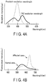
- FIG. 4A is a graph showing absorption intensity characteristics regarding autofluorescent substances.
- FIG. 4B is a graph showing fluorescence intensity characteristics. These graphs show the absorption intensity characteristics and fluorescence intensity characteristics of Flavin Adenine Dinucleotide (FAD) and porphyrin which are autofluorescent substances correlated with tumors.
- FAD Flavin Adenine Dinucleotide
- porphyrin generates fluorescence by light ray having a central wavelength of 400 nm
- FAD generates fluorescence by light ray having a central wavelength of 380 nm and light ray having a central wavelength of 450 nm. Images obtained by imaging such fluorescences are autofluorescence images.
- FIG. 5 is a block diagram showing the configuration of a medical image formation apparatus according to a first embodiment of the present invention.
- This medical image formation apparatus 100 displays a special light image 1, a special light image 2, a special light image 3, and a white light image with high image accuracy.
- the special light images are observation images which are obtained by the application of light ray having a particular wavelength and in which a particular feature of an observation target is enhanced.
- the special light image 1 as an example is an autofluorescence image.
- the special light image 2 as an example is a blood vessel enhanced image.
- the special light image 3 as an example is an oxygen saturation image.
- the white light image is a normal observation image which is obtained by the application of white light ray and in which the particular feature of the observation target is not enhanced. This white light image is used in, for example, screening.
- the medical image formation apparatus 100 shown in FIG. 5 includes laser emitting elements (hereinafter briefly referred to as lasers) 1 to 7 as illumination light sources.
- lasers are, for example, semiconductor lasers, and are different in emission wavelength.
- the laser 1 applies light ray having a wavelength of 400 nm
- the laser 2 applies light ray having a wavelength of 450 nm
- the laser 3 applies light ray having a wavelength of 420 nm
- the laser 4 applies light ray having a wavelength of 540 nm
- the laser 5 applies light ray of 640 nm
- the laser 6 applies light ray of 590 nm
- the laser 7 applies light ray of 560 nm.
- the lasers 1 to 7 are connected to a light source control unit 8.
- the light source control unit 8 is connected to an image selection unit 9 and an observation mode storage unit 10.
- the image selection unit 9 is an operational component such as a touch panel, and receives an operation by a user to select a kind of observation image.
- the observation mode storage unit 10 stores a laser output condition (e.g., laser lighting start timing, a lighting period, and a lighting cycle) for each observation mode suited to a combination of the observation images selected by the image selection unit 9.
- the light source control unit 8 acquires the laser output condition corresponding to an observation mode from the observation mode storage unit 10, and controls the lighting of the lasers 1 to 7 so that the observation images selected by the image selection unit 9 can be formed under the acquired laser output condition. Details will be described later.
- the light distribution conversion member 16 is preferably, for example, a lens, a surface diffusion component having a light diffusion function in the surface, an internal diffusion component including therein one of micro components different in refractive index and reflectance, or a multiple optical component which is a combination of the above.
- the imaging unit 18 has, for example, red (R), green (G), and blue (B) image pickup devices (e.g. CCD image pickup devices) so that the image pickup devices of each color are regularly arranged flush.
- the R image pickup devices are image pickup devices having a peak of sensitivity in an R wavelength band (about 600 nm).
- the G image pickup devices are image pickup devices having a peak of sensitivity in a G wavelength band (about 540 nm).
- the B image pickup devices are image pickup devices having a peak of sensitivity in a B wavelength band (about 480 nm). Each of these image pickup devices photoelectrically converts the light ray having the corresponding wavelength band to generate an image signal for each color.
- An illumination imaging synchronization unit 20 is connected to the imaging unit 18.
- the illumination imaging synchronization unit 20 is also connected to the light source control unit 8 and an image distribution unit 22.
- the illumination imaging synchronization unit 20 outputs synchronization signals to the light source control unit 8, the imaging unit 18, and the image distribution unit 22 to synchronize the illuminations by the lasers 1 to 7, imaging by the imaging unit 18, and image distribution by the image distribution unit 22.
- the imaging unit 18 is connected to the image distribution unit 22.
- the image distribution unit 22 is connected to each of image formation units provided in an image signal processing circuit 24, that is, a special light 1 image formation unit 24a, a special light 2 image formation unit 24b, a special light 3 image formation unit 24c, and a white light image formation unit 24d.
- the image distribution unit 22 sends, to the image formation units, an image signal received from the imaging unit 18 in response to the input of the synchronization signal from the illumination imaging synchronization unit 20.
- the special light 1 image formation unit 24a forms the special light image 1 (autofluorescence image) from the received image signal.
- the special light 2 image formation unit 24b forms the special light image 2 (blood vessel enhanced image) from the received image signal.
- the special light 3 image formation unit 24c forms the special light image 3 (oxygen saturation image) from the received image signal.
- the white light image formation unit 24d forms the white light image from the received image signal.
- An image display unit 26 receives the observation images formed by the image formation units of the image signal processing circuit 24, and displays the observation images so that, for example, the user can easily recognize the observation images.
- the image display unit 26 divides one screen into four parts to display the respective observation images in parallel.
- a brightness correction unit 28 receives the observation images from the image display unit 26, and then determines the brightness of the observation images displayed on the image display unit 26. When the brightness of the observation images displayed on the image display unit 26 is not proper brightness, the brightness correction unit 28 outputs a correction signal to the light source control unit 8 so that the brightness of the observation images will be the proper brightness.
- the user operates the image selection unit 9 to select an observation image.
- an observation image By way of example, all of the special light images 1, 2, and 3 and the white light image are selected.
- the light source control unit 8 acquires, from the observation mode storage unit 10, a laser output condition corresponding to the observation mode suited to the selected observation image.
- FIG. 7 shows an example of a laser output condition in which the special light images 1, 2, and 3, and the white light image are simultaneously displayed.
- the laser 1 is only used to form the special light image 1 (autofluorescence image). Therefore, the lighting start timing of the laser 1 is the start timing of a 1/4 frame which is the formation period of the special light image 1.
- the lighting period of the laser 1 is the period of 1/4 of one frame.
- the lighting cycle is the period of one frame.
- the laser 2 is used to form the special light image 1 and to form the white light image. Therefore, the lighting start timing of the laser 2 is the start timing of the 1/4 frame which is the formation period of the special light image 1 and the start timing of the 4/4 frame which is the formation period of the white light image.
- the 4/4 frame and the 1/4 frame are continuous as shown in FIG. 7 . Therefore, the actual lighting start timing of the laser 2 is the start timing of the 1/4 frame and the start timing of the 4/4 frame only in the initial frame, and is the start timing of the 4/4 frame in the previous frame in and after the second frame.
- the lighting period of the laser 2 is the period of 1/4 of one frame only in the initial 4/4 frame, and is the period of 1/2 of one frame in the subsequent frames.
- the lighting cycle of the laser 2 is the period of 3/4 of one frame only in the initial 1/4 frame to the 4/4 frame, and is the period of one frame in the subsequent frames.
- the laser 3 is only used to form the special light image 2 (blood vessel enhanced image) . Therefore, the lighting start timing of the laser 3 is the start timing of a 2/4 frame which is the formation period of the special light image 2.
- the lighting period of the laser 3 is the period of 1/4 of one frame.
- the lighting cycle is the period of one frame.
- the laser 4 is used to form the special light image 2 and to form the white light image.
- the lighting start timing of the laser 4 is the start timing of the 2/4 frame which is the formation period of the special light image 2 and the start timing of the 4/4 frame which is the formation period of the white light image.
- the lighting period of the laser 4 is the period of 1/4 of one frame.
- the lighting cycle is the period of a 1/2 frame.
- the laser 5 is used to form the special light image 2 and to form the white light image. Therefore, the lighting start timing of the laser 5 is the start timing of the 2/4 frame which is the formation period of the special light image 2 and the start timing of the 4/4 frame which is the formation period of the white light image.
- the lighting period of the laser 5 is the period of 1/4 of one frame.
- the lighting cycle is the period of a 1/2 frame.
- the laser 6 is used to form the special light image 3 (oxygen saturation image) and to form the white light image. Therefore, the lighting start timing of the laser 6 is the start timing of the 3/4 frame which is the formation period of the special light image 3 and the start timing of the 4/4 frame which is the formation period of the white light image.
- the 3/4 frame and the 4/4 frame are continuous, so that the actual start timing of the laser 6 is the start timing of the 3/4 frame.
- the lighting period of the laser 6 is the period of 1/2 of one frame.
- the lighting cycle is the period of one frame.
- the laser 7 is only used to form the special light image 3. Therefore, the lighting start timing of the laser 7 is the start timing of a 3/4 frame which is the formation period of the special light image 3.
- the lighting period of the laser 7 is the period of 1/4 of one frame.
- the lighting cycle is the period of one frame.
- the light source control unit 8 turns on the lasers 1 to 7.
- the imaging unit 18 images return light rays, from the observation target, of the laser light rays emitted from the lasers 1 to 7 in accordance with the synchronization signal from the illumination imaging synchronization unit 20 to generate an image signal, the sends the generated image signal to the image distribution unit 22.
- the image distribution unit 22 identifies the kind of observation image to be formed by the synchronization signal from the illumination imaging synchronization unit 20, and in accordance with the result of this identification, sends the image signal received from the imaging unit 18 to the necessary image formation units among the special light 1 image formation unit 24a, the special light 2 image formation unit 24b, the special light 3 image formation unit 24c, and the white light image formation unit 24d.
- the image formation units form corresponding observation images from the received image signal, and send the formed observation images to the image display unit 26.
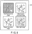
- the image display unit 26 displays the received observation images so that the user can easily see the observation images. For example, the image display unit 26 displays four observation images in parallel as shown in FIG. 8 .
- the observation images formed in the image formation unit are input to the brightness correction unit 28 from the image display unit 26.
- the brightness correction unit 28 instructs the light source control unit 8 to correct the outputs of the lasers 1 to 7 so that the brightness of the observation images to be displayed on the image display unit 26 will be proper.
- FIG. 9 shows an example of a laser output condition in which the special light image 1 and the white light image are only selected.
- the two observation images are displayed in parallel as shown in FIG. 10 .
- the lighting periods of the lasers 1, 4, 5, and 6 have only to be the period of 1/2 of one frame.
- the laser 2 may be kept turned on.
- the formation period of the observation image can be longer, so that if the period of one frame is the same as that in the example of FIG. 7 , the application time of the laser light to the observation target and the imaging period can be longer than those in the example of FIG. 7 . Therefore, brighter observation images can be displayed in the example of FIG. 9 than in the example of FIG. 7 .
- the lasers are used to form the white light ray and the special light rays.
- the lasers can be highly efficiently introduced into a small-diameter light ray guiding component such as a fiber with ease, and can provide considerably bright illumination light in comparison to an LED light source or a gas light source.
- the laser is used to form the special light ray so that image information specific to its wavelength can be acquired, in comparison to a light source having a broad spectrum such as the LED light source. Therefore, the image accuracy is high.
- An image desired by the user can be only formed by the image selection unit 9.
- the lighting period of the laser and the imaging period for one observation image are maximized in one frame. Consequently, an image with high image accuracy can be acquired.
- the laser lighting start timings, the laser lighting periods, and the laser lighting cycles corresponding to the observation modes are stored in the observation mode storage unit 10. This can also reduce power consumption. If the lighting cycles of different lasers are independently changed, the laser can be kept turned on across the frames in which different kinds of images are obtained. Thus, a common laser can be lit without any circuit load. This can also reduce power consumption.
- An image signal is transferred to the image formation unit by the illumination imaging synchronization unit 20 by proper timing. This can also reduce power consumption.
- the medical image formation apparatus 100 is, but not exclusively, configured to create the white light image only by the lasers prepared for the special light images.
- a laser for the white light image may be additionally prepared.
- a different laser is prepared for each of more than one kind of laser light ray used for the special light ray in the medical image formation apparatus 100 according to the present embodiment, the same laser may also be used if there is any available technique.
- the excitation central wavelength of porphyrin and the wavelength at which the reducing substance spectrum corresponds to that of an oxide regarding hemoglobin are the same wavelength of 450 nm. Therefore, one laser of 450 nm alone may be used for the laser to form the autofluorescence image and the laser to form the oxygen saturation image.
- FIG. 11 is a block diagram showing the configuration of a medical image formation apparatus according to the second embodiment of the present invention.
- the medical image formation apparatus 100 according to the present embodiment is simpler in configuration than that in the first embodiment.
- the same components as those in the first embodiment are not described below.
- the medical image formation apparatus 100 has lasers 1 to 4 as illumination light sources.
- the laser 1 applies light ray having a wavelength of 400 nm
- the laser 2 applies light ray having a wavelength of 450 nm
- the laser 3 applies light having a wavelength of 540 nm
- the laser 4 applies light ray having a wavelength of 640 nm.
- two observation images a special light image 1 (blood vessel enhanced image) and a white light image are only formed at the maximum. Therefore, there are also two image formation units alone.
- FIG. 12 shows an example of a laser output condition in which the special light image 1 and the white light image are only selected in the second embodiment.
- the laser 1 and the laser 3 are turned on in the formation period of the special light image 1.
- the laser 2, the laser 3, and the laser 4 are turned on in the formation period of the white light image.
- the lighting periods and laser lighting cycles may be similar to those in FIG. 9 .
- two observation images shown in FIG. 13 are displayed in parallel.
- the laser is newly provided for the white light image in the second embodiment, so that it is possible to obtain a white light image having high color rendering properties even if the number of lasers is three.
Landscapes
- Health & Medical Sciences (AREA)
- Life Sciences & Earth Sciences (AREA)
- Surgery (AREA)
- Physics & Mathematics (AREA)
- Engineering & Computer Science (AREA)
- Optics & Photonics (AREA)
- Veterinary Medicine (AREA)
- Pathology (AREA)
- Public Health (AREA)
- Biophysics (AREA)
- Biomedical Technology (AREA)
- Heart & Thoracic Surgery (AREA)
- Medical Informatics (AREA)
- Molecular Biology (AREA)
- Animal Behavior & Ethology (AREA)
- General Health & Medical Sciences (AREA)
- Radiology & Medical Imaging (AREA)
- Nuclear Medicine, Radiotherapy & Molecular Imaging (AREA)
- General Physics & Mathematics (AREA)
- Astronomy & Astrophysics (AREA)
- Signal Processing (AREA)
- Multimedia (AREA)
- Spectroscopy & Molecular Physics (AREA)
- Theoretical Computer Science (AREA)
- Endoscopes (AREA)
- Exposure Control For Cameras (AREA)
- Stroboscope Apparatuses (AREA)
- Closed-Circuit Television Systems (AREA)
Abstract
Description
- The present invention relates to a medical image formation apparatus.
- In contrast to conventionally used gas light sources, solid-state light sources have such advantages as low power consumption, high connection efficiency, small sizes, high-speed switchability. Technical innovations for such solid-state light sources are remarkable. Among these solid-state light sources, a solid-state laser in particular has such a feature as extremely high optical density in an emission area. Owing to this feature, what is known as fiber light sources configured by combining the solid-state laser with, for example, optical fibers are under active development. The fiber light sources are suited to illumination in a thin structure, and are being further applied to, for example, endoscopes.
- As an example of a medical image formation apparatus that uses the fiber light source,
Jpn. Pat. Appln. KOKAI Publication No. 2011-200572 Jpn. Pat. Appln. KOKAI Publication No. 2011-200572 Jpn. Pat. Appln. KOKAI Publication No. 2011-200572 - In
Jpn. Pat. Appln. KOKAI Publication No. 2011-200572 Jpn. Pat. Appln. KOKAI Publication No. 2011-200572 - The present invention has been made in view of these circumstances, and is intended to provide a medical image formation apparatus which achieves lower costs, a lower volume, and low power consumption and which is high in image reproduction accuracy.
- To achieve the object, a medical image formation apparatus according to an aspect of the invention comprises: laser emitting elements which emit laser light rays different in wavelength; an image selection unit to select a kind of observation image; a light source control unit which controls the lighting of the laser emitting elements in accordance with an observation mode corresponding to a combination of the selected observation image; an imaging unit which images return light ray of the laser light ray from an observation target and then outputs the return light ray as an image signal; and an image signal processing circuit which forms the observation images from the image signal from the imaging unit, wherein a laser emitting element which emits a laser light ray having a common wavelength is included between the laser emitting element whose lighting is controlled by the light source control unit when the kind of selected observation image is a first observation image and the laser emitting element whose lighting is controlled by the light source control unit when the kind of selected observation image is a second observation image.
-
-
FIG. 1 is a graph showing results of the calculation of a general color rendering index Ra for various wavelengths and various numbers of lasers; -
FIG. 2A is a diagram schematically showing a sectional structure of a living mucous membrane; -
FIG. 2B is a diagram schematically showing the relation between the wavelengths and penetration depths; -
FIG. 3 is a graph showing the wavelength dependence of the absorption coefficient of blood hemoglobin; -
FIG. 4A is a graph showing absorption intensity characteristics regarding autofluorescent substances; -
FIG. 4B is a graph showing fluorescence intensity characteristics; -
FIG. 5 is a block diagram showing the configuration of a medical image formation apparatus according to a first embodiment of the present invention; -
FIG. 6 is a diagram showing an example of a laser output condition in which all of aspecial light image 1, aspecial light image 2, aspecial light image 3, and a white light image are selected; -
FIG. 7 is a diagram showing an example of a laser output condition in which thespecial light images -
FIG. 8 is a diagram showing an example of parallel display of four observation images; -
FIG. 9 is a diagram showing an example of a laser output condition in which thespecial light image 1 and the white light image are only selected; -
FIG. 10 is a diagram showing an example of parallel display of two observation images; -
FIG. 11 is a block diagram showing the configuration of a medical image formation apparatus according to a second embodiment of the present invention; -
FIG. 12 is a diagram showing an example of a laser output condition in which both of thespecial light image 1 and the white light image are selected in the second embodiment of the present invention; and -
FIG. 13 is a diagram showing an example of parallel display of two observation images in the second embodiment of the present invention. - Hereinafter, embodiments of the present invention will be described with reference to the drawings. First, a prerequisite technique for the present embodiments is described. It has heretofore been considered that the emission of light having no wavelength lack in the whole visible light is essential to a white illumination apparatus which is high in quality and high in image reproduction accuracy. However, it has recently been increasingly obvious that even illumination light ray which is a combination of single-wavelength light rays such as laser light rays is high enough in the performance (color rendering properties) as illumination light ray (e.g., see A. Neumann et al., Opt. Exp., 19, S4, A982 (July 4, 2011)).
- The applicant calculated a general color rendering index Ra which is one of an illuminator quality evaluation parameter defined by, for example, Japanese Industrial Standards (JIS), for various wavelengths and various numbers of lasers. As a result, as shown in
FIG. 1 , it was found that performance equal to or more than that of conventionally used general illumination having a broad spectrum could be obtained by an appropriate combination of laser light rays of different wavelengths. Specifically, at least four lasers allow the general color rendering index Ra to be 80, and allow sufficient performance as an illumination light source to be obtained. - A laser can output light ray higher in light density and parallelism from a smaller emission area than a gas light source or an LED. Therefore, a laser as a white light observation light source that requires color rendering properties has an advantage of being easy to highly efficiently introduce into a small-diameter light ray guiding component such as a fiber in an observation apparatus such as an endoscope apparatus assuming observations in closed spaces (low power consumption, high-luminance illumination). Owing to a narrow spectral characteristic of the laser, it is also possible to obtain the advantage of ease of accurately acquiring the wavelength characteristic of a target part for a particular substance for special light observations that have been extensively developed in the field of endoscopes in recent years. The special light observations include, for example, observations of a blood vessel enhanced image, an oxygen saturation image, and an autofluorescence image. Each of the observation images is described below.
- It is known that when light rays ranging from ultraviolet light ray to near-infrared light ray are applied to the inside of a living body, the application of the light ray having a longer wavelength leads to a greater light penetration depth due to the scattering characteristic and absorption characteristic of the living body. For example, if a living mucous membrane has a sectional structure that is schematically shown in
FIG. 2A , the light ray which has entered the living body penetrates the living body nearly to the penetration depth, and is, for example, absorbed and scattered in the range of this depth and then returns. If this return light ray is observed, information regarding the periphery of a deep area of the penetration depth can be observed. As shown inFIG. 2B , a wavelength light ray (B light) having a short wavelength (400s nm) only penetrates to the vicinity of the surface layer, and is absorbed and scattered in the vicinity of this part. The return light ray in this instance is emitted from the surface of the living body. As shown inFIG. 2B , a wavelength light ray (G light) having an intermediate wavelength (500s nm) penetrates to a range deeper than the surface layer, and is absorbed and scattered in the vicinity of this part. The return light ray in this instance is emitted from the surface of the living body. Owing to this return light ray, information regarding a deeper part can be acquired in comparison to that in the case of the wavelength light ray having the short wavelength. Moreover, as shown inFIG. 2B , a wavelength light ray (R light) having a long wavelength (600s nm) penetrates to a much deeper range, and is absorbed and scattered in the vicinity of this part. The return light ray in this instance is emitted from the surface of the living body. Owing to this return light ray, information regarding a deeper part can be acquired in comparison to that in the case of the wavelength light ray having the intermediate wavelength. -
FIG. 3 shows the wavelength dependence of the absorption coefficient of blood hemoglobin. As shown inFIG. 3 , there is a slight difference of absorption spectrum between oxygenated hemoglobin and reduced hemoglobin. When light ray having a wavelength of 400s nm at which the absorption coefficient of hemoglobin is high is applied to the living body, an image in which blood vessels existing in the surface layer of the living body are mainly enhanced can be acquired. Similarly, when light ray having a wavelength of 500s nm at which the absorption coefficient of hemoglobin is high is applied to the living body, an image in which blood vessels existing in the intermediate layer of the living body are mainly enhanced can be acquired. When light ray having a wavelength of 600 nm or more is applied to the living body, an image in which blood vessels existing in the deep layer are mainly enhanced can be acquired. These observation images are blood vessel enhanced images. - The oxygen saturation of hemoglobin is calculated by obtaining the amount of oxygenated hemoglobin in the total amount of hemoglobin. As is evident from
FIG. 3 , wavelengths of 450 nm, 540 nm, and 805 nm are wavelengths at which there is little difference of absorption coefficient between oxygenated hemoglobin and reduced hemoglobin. In contrast, wavelengths of 430 nm, 560 nm, and 760 nm are wavelengths at which the reduced hemoglobin is higher in absorption coefficient, and wavelengths of 470 nm, 590 nm, and 840 nm are wavelengths at which the oxygenated hemoglobin is higher in absorption coefficient. Thus, light ray having a wavelength at which the absorption coefficients of the oxygenated hemoglobin and the reduced hemoglobin are reversed is selected and applied to the living body, and image information in each wavelength range obtained in this way is allocated to, for example, each of red, green, and blue colors and observed, so that changes of the oxygen saturation can be more easily taken as the changes of the color of the image. Such observation images are oxygen saturation images. Here, the penetration depth of light ray is greater at longer wavelengths as described above, so that an oxygen saturation image regarding blood vessels in the surface layer can be displayed when light ray having a wavelength of 400s nm is used, an oxygen saturation image regarding blood vessels in the intermediate layer can be displayed when light ray having a wavelength of 500s nm is used, and an oxygen saturation image regarding blood vessels in the deep layer can be displayed when light ray having a wavelength of 600 nm or more is used. -
FIG. 4A is a graph showing absorption intensity characteristics regarding autofluorescent substances.FIG. 4B is a graph showing fluorescence intensity characteristics. These graphs show the absorption intensity characteristics and fluorescence intensity characteristics of Flavin Adenine Dinucleotide (FAD) and porphyrin which are autofluorescent substances correlated with tumors. As is evident from the graph inFIG. 4A , porphyrin generates fluorescence by light ray having a central wavelength of 400 nm, and FAD generates fluorescence by light ray having a central wavelength of 380 nm and light ray having a central wavelength of 450 nm. Images obtained by imaging such fluorescences are autofluorescence images. Here, the fluorescence intensity of autofluorescence varies between an affected area and a normal area. That is, while fluorescence having a peak at around 550 nm is generated in the normal area, fluorescence having two peaks at 560 nm and 630 nm is generated in the affected area. It is known that porphyrin is accumulated in an area affected by, for example, cancer. Therefore, fluorescence of 630 nm regarding the affected area shown inFIG. 4B is fluorescence derived from porphyrin. Thus, by capturing the difference of fluorescence intensity of porphyrin, it is possible to distinguish the affected area from the normal area (reference: Tamura, Mamoru, "Series/Photobiology Vol. 6 Photomedicine Diagnosis", edited by Photobiology Association of Japan, Kyoritsu Shuppan Co., Ltd., Mar. 18, 2001). -
FIG. 5 is a block diagram showing the configuration of a medical image formation apparatus according to a first embodiment of the present invention. This medicalimage formation apparatus 100 displays a speciallight image 1, a speciallight image 2, a speciallight image 3, and a white light image with high image accuracy. The special light images are observation images which are obtained by the application of light ray having a particular wavelength and in which a particular feature of an observation target is enhanced. The speciallight image 1 as an example is an autofluorescence image. The speciallight image 2 as an example is a blood vessel enhanced image. Moreover, the speciallight image 3 as an example is an oxygen saturation image. The white light image is a normal observation image which is obtained by the application of white light ray and in which the particular feature of the observation target is not enhanced. This white light image is used in, for example, screening. - The medical
image formation apparatus 100 shown inFIG. 5 includes laser emitting elements (hereinafter briefly referred to as lasers) 1 to 7 as illumination light sources. These lasers are, for example, semiconductor lasers, and are different in emission wavelength. By way of example, thelaser 1 applies light ray having a wavelength of 400 nm, thelaser 2 applies light ray having a wavelength of 450 nm, thelaser 3 applies light ray having a wavelength of 420 nm, thelaser 4 applies light ray having a wavelength of 540 nm, thelaser 5 applies light ray of 640 nm, thelaser 6 applies light ray of 590 nm, and thelaser 7 applies light ray of 560 nm. - The
lasers 1 to 7 are connected to a lightsource control unit 8. The lightsource control unit 8 is connected to an image selection unit 9 and an observationmode storage unit 10. The image selection unit 9 is an operational component such as a touch panel, and receives an operation by a user to select a kind of observation image. The observationmode storage unit 10 stores a laser output condition (e.g., laser lighting start timing, a lighting period, and a lighting cycle) for each observation mode suited to a combination of the observation images selected by the image selection unit 9. The lightsource control unit 8 acquires the laser output condition corresponding to an observation mode from the observationmode storage unit 10, and controls the lighting of thelasers 1 to 7 so that the observation images selected by the image selection unit 9 can be formed under the acquired laser output condition. Details will be described later. - For example, an example of a laser output condition in which all of the special light image 1 (autofluorescence image), the special light image 2 (blood vessel enhanced image), the special light image 3 (oxygen saturation image), and the white light image are selected is shown in
FIG. 6 . This laser output condition is a laser output condition for an observation mode in which the selected four observation images are simultaneously displayed. When a cycle in which an image is displayed is one frame, a 1/4 frame is a period to form the speciallight image 1 in the example ofFIG. 6 , and thelasers light image 2, and thelasers light image 3, and thelasers lasers - The
lasers 1 to 7 are connected to acombiner 12 viaoptical fibers 11. Thecombiner 12 multiplexes laser light rays guided by theoptical fibers 11. Thecombiner 12 is connected to a lightdistribution conversion member 16 provided at the distal end of ascope insertion portion 14 via anoptical fiber 13. The lightdistribution conversion member 16 adjusts the distribution of a mixed light ray guided by theoptical fiber 13 to a state suited to imaging (e.g. an optimum light distribution spread angle), and then emits the light ray toward the unshown observation target. Here, the lightdistribution conversion member 16 is preferably, for example, a lens, a surface diffusion component having a light diffusion function in the surface, an internal diffusion component including therein one of micro components different in refractive index and reflectance, or a multiple optical component which is a combination of the above. - An
imaging unit 18 is further provided at the distal end of ascope insertion portion 14. Theimaging unit 18 has, for example, red (R), green (G), and blue (B) image pickup devices (e.g. CCD image pickup devices) so that the image pickup devices of each color are regularly arranged flush. The R image pickup devices are image pickup devices having a peak of sensitivity in an R wavelength band (about 600 nm). Similarly, the G image pickup devices are image pickup devices having a peak of sensitivity in a G wavelength band (about 540 nm). The B image pickup devices are image pickup devices having a peak of sensitivity in a B wavelength band (about 480 nm). Each of these image pickup devices photoelectrically converts the light ray having the corresponding wavelength band to generate an image signal for each color. - An illumination
imaging synchronization unit 20 is connected to theimaging unit 18. The illuminationimaging synchronization unit 20 is also connected to the lightsource control unit 8 and animage distribution unit 22. The illuminationimaging synchronization unit 20 outputs synchronization signals to the lightsource control unit 8, theimaging unit 18, and theimage distribution unit 22 to synchronize the illuminations by thelasers 1 to 7, imaging by theimaging unit 18, and image distribution by theimage distribution unit 22. - The
imaging unit 18 is connected to theimage distribution unit 22. Theimage distribution unit 22 is connected to each of image formation units provided in an imagesignal processing circuit 24, that is, aspecial light 1image formation unit 24a, aspecial light 2image formation unit 24b, aspecial light 3image formation unit 24c, and a white lightimage formation unit 24d. Theimage distribution unit 22 sends, to the image formation units, an image signal received from theimaging unit 18 in response to the input of the synchronization signal from the illuminationimaging synchronization unit 20. Thespecial light 1image formation unit 24a forms the special light image 1 (autofluorescence image) from the received image signal. Thespecial light 2image formation unit 24b forms the special light image 2 (blood vessel enhanced image) from the received image signal. Thespecial light 3image formation unit 24c forms the special light image 3 (oxygen saturation image) from the received image signal. The white lightimage formation unit 24d forms the white light image from the received image signal. - An
image display unit 26 receives the observation images formed by the image formation units of the imagesignal processing circuit 24, and displays the observation images so that, for example, the user can easily recognize the observation images. For example, theimage display unit 26 divides one screen into four parts to display the respective observation images in parallel. - A
brightness correction unit 28 receives the observation images from theimage display unit 26, and then determines the brightness of the observation images displayed on theimage display unit 26. When the brightness of the observation images displayed on theimage display unit 26 is not proper brightness, thebrightness correction unit 28 outputs a correction signal to the lightsource control unit 8 so that the brightness of the observation images will be the proper brightness. - Next, the operation of the medical
image formation apparatus 100 according to the present embodiment is described. First, the user operates the image selection unit 9 to select an observation image. By way of example, all of the speciallight images source control unit 8 acquires, from the observationmode storage unit 10, a laser output condition corresponding to the observation mode suited to the selected observation image.FIG. 7 shows an example of a laser output condition in which the speciallight images FIG. 7 , thelaser 1 is only used to form the special light image 1 (autofluorescence image). Therefore, the lighting start timing of thelaser 1 is the start timing of a 1/4 frame which is the formation period of the speciallight image 1. The lighting period of thelaser 1 is the period of 1/4 of one frame. Moreover, the lighting cycle is the period of one frame. In contrast, thelaser 2 is used to form the speciallight image 1 and to form the white light image. Therefore, the lighting start timing of thelaser 2 is the start timing of the 1/4 frame which is the formation period of the speciallight image 1 and the start timing of the 4/4 frame which is the formation period of the white light image. However, when repeated display is performed, the 4/4 frame and the 1/4 frame are continuous as shown inFIG. 7 . Therefore, the actual lighting start timing of thelaser 2 is the start timing of the 1/4 frame and the start timing of the 4/4 frame only in the initial frame, and is the start timing of the 4/4 frame in the previous frame in and after the second frame. The lighting period of thelaser 2 is the period of 1/4 of one frame only in the initial 4/4 frame, and is the period of 1/2 of one frame in the subsequent frames. Moreover, the lighting cycle of thelaser 2 is the period of 3/4 of one frame only in the initial 1/4 frame to the 4/4 frame, and is the period of one frame in the subsequent frames. Thelaser 3 is only used to form the special light image 2 (blood vessel enhanced image) . Therefore, the lighting start timing of thelaser 3 is the start timing of a 2/4 frame which is the formation period of the speciallight image 2. The lighting period of thelaser 3 is the period of 1/4 of one frame. Moreover, the lighting cycle is the period of one frame. Thelaser 4 is used to form the speciallight image 2 and to form the white light image. Therefore, the lighting start timing of thelaser 4 is the start timing of the 2/4 frame which is the formation period of the speciallight image 2 and the start timing of the 4/4 frame which is the formation period of the white light image. The lighting period of thelaser 4 is the period of 1/4 of one frame. Moreover, the lighting cycle is the period of a 1/2 frame. Thelaser 5 is used to form the speciallight image 2 and to form the white light image. Therefore, the lighting start timing of thelaser 5 is the start timing of the 2/4 frame which is the formation period of the speciallight image 2 and the start timing of the 4/4 frame which is the formation period of the white light image. The lighting period of thelaser 5 is the period of 1/4 of one frame. Moreover, the lighting cycle is the period of a 1/2 frame. Thelaser 6 is used to form the special light image 3 (oxygen saturation image) and to form the white light image. Therefore, the lighting start timing of thelaser 6 is the start timing of the 3/4 frame which is the formation period of the speciallight image 3 and the start timing of the 4/4 frame which is the formation period of the white light image. The 3/4 frame and the 4/4 frame are continuous, so that the actual start timing of thelaser 6 is the start timing of the 3/4 frame. The lighting period of thelaser 6 is the period of 1/2 of one frame. Moreover, the lighting cycle is the period of one frame. Thelaser 7 is only used to form the speciallight image 3. Therefore, the lighting start timing of thelaser 7 is the start timing of a 3/4 frame which is the formation period of the speciallight image 3. The lighting period of thelaser 7 is the period of 1/4 of one frame. Moreover, the lighting cycle is the period of one frame. - In accordance with the above output condition and the synchronization signal from the illumination
imaging synchronization unit 20, the lightsource control unit 8 turns on thelasers 1 to 7. Theimaging unit 18 images return light rays, from the observation target, of the laser light rays emitted from thelasers 1 to 7 in accordance with the synchronization signal from the illuminationimaging synchronization unit 20 to generate an image signal, the sends the generated image signal to theimage distribution unit 22. - The
image distribution unit 22 identifies the kind of observation image to be formed by the synchronization signal from the illuminationimaging synchronization unit 20, and in accordance with the result of this identification, sends the image signal received from theimaging unit 18 to the necessary image formation units among thespecial light 1image formation unit 24a, thespecial light 2image formation unit 24b, thespecial light 3image formation unit 24c, and the white lightimage formation unit 24d. The image formation units form corresponding observation images from the received image signal, and send the formed observation images to theimage display unit 26. Theimage display unit 26 displays the received observation images so that the user can easily see the observation images. For example, theimage display unit 26 displays four observation images in parallel as shown inFIG. 8 . - The observation images formed in the image formation unit are input to the
brightness correction unit 28 from theimage display unit 26. Thebrightness correction unit 28 instructs the lightsource control unit 8 to correct the outputs of thelasers 1 to 7 so that the brightness of the observation images to be displayed on theimage display unit 26 will be proper. -
FIG. 9 shows an example of a laser output condition in which the speciallight image 1 and the white light image are only selected. When two observation images are only selected, the two observation images are displayed in parallel as shown inFIG. 10 . In such an observation mode, two observation images have only to be formed in one frame. Therefore, as shown inFIG. 9 , the lighting periods of thelasers laser 2 may be kept turned on. In the example ofFIG. 9 , the formation period of the observation image can be longer, so that if the period of one frame is the same as that in the example ofFIG. 7 , the application time of the laser light to the observation target and the imaging period can be longer than those in the example ofFIG. 7 . Therefore, brighter observation images can be displayed in the example ofFIG. 9 than in the example ofFIG. 7 . - As described above, in the present embodiment, the lasers are used to form the white light ray and the special light rays. The lasers can be highly efficiently introduced into a small-diameter light ray guiding component such as a fiber with ease, and can provide considerably bright illumination light in comparison to an LED light source or a gas light source. The laser is used to form the special light ray so that image information specific to its wavelength can be acquired, in comparison to a light source having a broad spectrum such as the LED light source. Therefore, the image accuracy is high.
- Furthermore, some of the lasers for the special light rays are utilized to construct the white light image, so that the number of lasers can be reduced for reduction in costs and volume. Since four lasers for the white light image are prepared, the color rendering properties of the white light image are ensured. Moreover, other lasers are not turned on when the white light image is acquired, so that the white light image with high image accuracy can be formed. Since more than one kind of special light image are also used in common, the number of lasers can be further reduced for reduction in costs and volume.
- An image desired by the user can be only formed by the image selection unit 9. Thus, there is no unnecessary lighting of the lasers, and there are no unnecessary image acquisition periods. Therefore, the lighting period of the laser and the imaging period for one observation image are maximized in one frame. Consequently, an image with high image accuracy can be acquired.
- There is no unnecessary driving of the lasers if the laser lighting start timings, the laser lighting periods, and the laser lighting cycles corresponding to the observation modes are stored in the observation
mode storage unit 10. This can also reduce power consumption. If the lighting cycles of different lasers are independently changed, the laser can be kept turned on across the frames in which different kinds of images are obtained. Thus, a common laser can be lit without any circuit load. This can also reduce power consumption. - An image signal is transferred to the image formation unit by the illumination
imaging synchronization unit 20 by proper timing. This can also reduce power consumption. - Here, the medical
image formation apparatus 100 according to the present embodiment is, but not exclusively, configured to create the white light image only by the lasers prepared for the special light images. In the case of a configuration that can not create a high-quality white light image only by the lasers prepared for the special light images, a laser for the white light image may be additionally prepared. Although a different laser is prepared for each of more than one kind of laser light ray used for the special light ray in the medicalimage formation apparatus 100 according to the present embodiment, the same laser may also be used if there is any available technique. For example, the excitation central wavelength of porphyrin and the wavelength at which the reducing substance spectrum corresponds to that of an oxide regarding hemoglobin are the same wavelength of 450 nm. Therefore, one laser of 450 nm alone may be used for the laser to form the autofluorescence image and the laser to form the oxygen saturation image. - Next, a second embodiment of the present invention is described.
FIG. 11 is a block diagram showing the configuration of a medical image formation apparatus according to the second embodiment of the present invention. The medicalimage formation apparatus 100 according to the present embodiment is simpler in configuration than that in the first embodiment. The same components as those in the first embodiment are not described below. - The medical
image formation apparatus 100 according to the second embodiment haslasers 1 to 4 as illumination light sources. By way of example, thelaser 1 applies light ray having a wavelength of 400 nm, thelaser 2 applies light ray having a wavelength of 450 nm, thelaser 3 applies light having a wavelength of 540 nm, and thelaser 4 applies light ray having a wavelength of 640 nm. In the second embodiment, two observation images: a special light image 1 (blood vessel enhanced image) and a white light image are only formed at the maximum. Therefore, there are also two image formation units alone. -
FIG. 12 shows an example of a laser output condition in which the speciallight image 1 and the white light image are only selected in the second embodiment. As shown inFIG. 12 , thelaser 1 and thelaser 3 are turned on in the formation period of the speciallight image 1. Thelaser 2, thelaser 3, and thelaser 4 are turned on in the formation period of the white light image. The lighting periods and laser lighting cycles may be similar to those inFIG. 9 . In this second embodiment, two observation images shown inFIG. 13 are displayed in parallel. - As described above, according to the present embodiment, the number of lasers and the number of other components can be much smaller than those in the first embodiment. The individual functions can be simpler than in the first embodiment, so that lower costs, a lower volume, and low power consumption can be achieved than in the first embodiment. The observation modes that are truly necessary for the user can be only formed, so that the laser lighting period and imaging period for one observation image are maximized in one frame. Consequently, an image with high image accuracy can be acquired.
- The laser is newly provided for the white light image in the second embodiment, so that it is possible to obtain a white light image having high color rendering properties even if the number of lasers is three.
Claims (10)
- A medical image formation apparatus comprising:laser emitting elements which emit laser light rays different in wavelength;an image selection unit to select a kind of observation image;a light source control unit which controls the lighting of the laser emitting elements in accordance with an observation mode corresponding to a combination of the selected observation image;an imaging unit which images return light ray of the laser light ray from an observation target and then outputs the return light ray as an image signal; andan image signal processing circuit which forms the observation images from the image signal from the imaging unit,wherein a laser emitting element which emits a laser light ray having a common wavelength is included between the laser emitting element whose lighting is controlled by the light source control unit when the kind of selected observation image is a first observation image and the laser emitting element whose lighting is controlled by the light source control unit when the kind of selected observation image is a second observation image.
- The medical image formation apparatus according to claim 1, wherein the first observation image and the second observation image are acquired in periods different from each other.
- The medical image formation apparatus according to claim 1, further comprising an observation mode storage unit to store lighting start timings, lighting periods, and lighting cycles of the laser emitting elements corresponding to the observation mode as a laser output condition,
wherein the light source control unit controls the lighting of the laser emitting elements based on the laser output condition stored in the observation mode storage unit. - The medical image formation apparatus according to claim 1, wherein at least some of the laser emitting elements are different in lighting period and lighting cycle.
- The medical image formation apparatus according to claim 1, wherein a laser emitting element which emits laser light rays having different wavelengths is included between the laser emitting element whose lighting is controlled by the light source control unit when the kind of selected observation image is the first observation image and the laser emitting element whose lighting is controlled by the light source control unit when the kind of selected observation image is the second observation image.
- The medical image formation apparatus according to claim 1, wherein the first observation image is an enhanced image in which a particular feature of the observation target is enhanced, and the second observation image is a normal image in which the particular feature of the observation target is not enhanced.
- The medical image formation apparatus according to claim 6, wherein the enhanced image is a special light image and the normal image is a white light image.
- The medical image formation apparatus according to claim 7, wherein at least four laser emitting elements which emit laser light rays of different wavelengths are used to form the white light image.
- The medical image formation apparatus according to claim 1, wherein the first observation image is a first enhanced image in which a particular feature of the observation target is enhanced, and the second observation image is a second enhanced image in which another particular feature of the observation target is enhanced.
- The medical image formation apparatus according to claim 9, wherein the first enhanced image and the second enhanced image are special light images.
Applications Claiming Priority (2)
| Application Number | Priority Date | Filing Date | Title |
|---|---|---|---|
| JP2014014869A JP2015139613A (en) | 2014-01-29 | 2014-01-29 | medical image forming apparatus |
| PCT/JP2015/051809 WO2015115320A1 (en) | 2014-01-29 | 2015-01-23 | Medical image formation device |
Publications (2)
| Publication Number | Publication Date |
|---|---|
| EP3100670A1 true EP3100670A1 (en) | 2016-12-07 |
| EP3100670A4 EP3100670A4 (en) | 2018-01-17 |
Family
ID=53756894
Family Applications (1)
| Application Number | Title | Priority Date | Filing Date |
|---|---|---|---|
| EP15742832.7A Withdrawn EP3100670A4 (en) | 2014-01-29 | 2015-01-23 | Medical image formation device |
Country Status (5)
| Country | Link |
|---|---|
| US (1) | US10226168B2 (en) |
| EP (1) | EP3100670A4 (en) |
| JP (1) | JP2015139613A (en) |
| CN (1) | CN105939651B (en) |
| WO (1) | WO2015115320A1 (en) |
Cited By (1)
| Publication number | Priority date | Publication date | Assignee | Title |
|---|---|---|---|---|
| EP3391805A4 (en) * | 2015-12-17 | 2019-09-18 | Olympus Corporation | Endoscope device |
Families Citing this family (11)
| Publication number | Priority date | Publication date | Assignee | Title |
|---|---|---|---|---|
| JP6285370B2 (en) * | 2015-01-22 | 2018-02-28 | 富士フイルム株式会社 | Endoscope processor device, operation method of endoscope processor device, endoscope control program, and endoscope system |
| CN107105996B (en) * | 2015-01-30 | 2018-11-20 | 奥林巴斯株式会社 | Lighting device, endoscopic system and tonal correction device |
| JP6654117B2 (en) * | 2016-08-31 | 2020-02-26 | 富士フイルム株式会社 | Endoscope system and method of operating endoscope system |
| JP7123135B2 (en) * | 2018-06-19 | 2022-08-22 | オリンパス株式会社 | Endoscope device, operating method and program for endoscope device |
| EP3911223A4 (en) | 2019-01-17 | 2022-10-19 | SBI Alapharma Canada, Inc. | DEVICES, SYSTEMS, AND METHODS FOR TUMOR VISUALIZATION AND REMOVAL |
| WO2020148726A1 (en) | 2019-01-17 | 2020-07-23 | Moleculight Inc. | Modular system for multi-modal imaging and analysis |
| EP3911222A4 (en) * | 2019-01-17 | 2023-02-01 | SBI Alapharma Canada, Inc. | Modular endoscopic system for visualization of disease |
| KR102266349B1 (en) * | 2019-05-27 | 2021-06-17 | 한국광기술원 | Hybrid imaging system for animal experiment and method thereof |
| USD1117133S1 (en) | 2021-08-23 | 2026-03-10 | Moleculight Inc. | Modular handheld imaging device |
| WO2023166694A1 (en) * | 2022-03-04 | 2023-09-07 | オリンパス株式会社 | Image processing device, living body observation system, and image processing method |
| EP4480385A1 (en) * | 2023-06-19 | 2024-12-25 | Leica Instruments (Singapore) Pte Ltd | Data processing device for a medical observation device such as a microscope or an endoscope and computer-implemented method for generating a digital reflectance color output image |
Family Cites Families (14)
| Publication number | Priority date | Publication date | Assignee | Title |
|---|---|---|---|---|
| DE10136191A1 (en) * | 2001-07-25 | 2003-02-20 | Wolf Gmbh Richard | Device for imaging and spectroscopic diagnosis of tissue |
| JP4648683B2 (en) * | 2004-11-09 | 2011-03-09 | Hoya株式会社 | Endoscope system |
| JP2008212317A (en) * | 2007-03-02 | 2008-09-18 | Seiko Epson Corp | Optical device and monitor device |
| JP2009207584A (en) * | 2008-03-03 | 2009-09-17 | Hoya Corp | Endoscope system |
| US20120245410A1 (en) | 2008-10-22 | 2012-09-27 | Davis Sean | Lotus massage systems and methods |
| JP5385188B2 (en) * | 2010-03-26 | 2014-01-08 | 富士フイルム株式会社 | Electronic endoscope system |
| JP2011243440A (en) * | 2010-05-19 | 2011-12-01 | Olympus Corp | Illumination device |
| US9523680B2 (en) * | 2010-06-30 | 2016-12-20 | Ambergen, Inc. | Global Proteomic screening of random bead arrays using mass spectrometry imaging |
| JP2012016545A (en) * | 2010-07-09 | 2012-01-26 | Fujifilm Corp | Endoscope apparatus |
| JP5460536B2 (en) * | 2010-09-24 | 2014-04-02 | 富士フイルム株式会社 | Electronic endoscope system |
| JP5611892B2 (en) * | 2011-05-24 | 2014-10-22 | 富士フイルム株式会社 | Endoscope system and method for operating endoscope system |
| JP2013027432A (en) * | 2011-07-26 | 2013-02-07 | Fujifilm Corp | Endoscope apparatus and method of manufacturing the same |
| JP5654511B2 (en) * | 2012-03-14 | 2015-01-14 | 富士フイルム株式会社 | Endoscope system, processor device for endoscope system, and method for operating endoscope system |
| JP5587932B2 (en) * | 2012-03-14 | 2014-09-10 | 富士フイルム株式会社 | Endoscope system, processor device for endoscope system, and method for operating endoscope system |
-
2014
- 2014-01-29 JP JP2014014869A patent/JP2015139613A/en active Pending
-
2015
- 2015-01-23 CN CN201580006447.2A patent/CN105939651B/en active Active
- 2015-01-23 WO PCT/JP2015/051809 patent/WO2015115320A1/en not_active Ceased
- 2015-01-23 EP EP15742832.7A patent/EP3100670A4/en not_active Withdrawn
-
2016
- 2016-07-28 US US15/221,664 patent/US10226168B2/en active Active
Cited By (1)
| Publication number | Priority date | Publication date | Assignee | Title |
|---|---|---|---|---|
| EP3391805A4 (en) * | 2015-12-17 | 2019-09-18 | Olympus Corporation | Endoscope device |
Also Published As
| Publication number | Publication date |
|---|---|
| JP2015139613A (en) | 2015-08-03 |
| US20160331218A1 (en) | 2016-11-17 |
| US10226168B2 (en) | 2019-03-12 |
| CN105939651A (en) | 2016-09-14 |
| EP3100670A4 (en) | 2018-01-17 |
| WO2015115320A1 (en) | 2015-08-06 |
| CN105939651B (en) | 2018-07-10 |
Similar Documents
| Publication | Publication Date | Title |
|---|---|---|
| US10226168B2 (en) | Medical image formation apparatus | |
| EP2754379B1 (en) | Endoscope system and image display method | |
| US8915844B2 (en) | Endoscope diagnostic apparatus | |
| JP5303012B2 (en) | Endoscope system, processor device for endoscope system, and method for operating endoscope system | |
| US9943230B2 (en) | Endoscope system, processor device of endoscope system, and image processing method | |
| EP2754378B1 (en) | ENDOSCOPE SYSTEM and PROCESSOR DEVICE THEREOF | |
| JP5329177B2 (en) | Imaging system and program | |
| EP2468186A1 (en) | Endoscopic diagnosis system | |
| US20110172492A1 (en) | Medical apparatus and endoscope apparatus | |
| US8633976B2 (en) | Position specifying system, position specifying method, and computer readable medium | |
| CN106132275B (en) | Observation image acquisition system and observation image acquisition method | |
| CN107072508A (en) | observation system | |
| CN106163375B (en) | Endoscope apparatus | |
| WO2013035694A1 (en) | Endoscope system, processor device and image display method | |
| EP1908393A1 (en) | Organism observing apparatus | |
| EP2666403B1 (en) | Endoscope system and processor device thereof | |
| JPWO2017046857A1 (en) | Endoscope device | |
| JP6732029B2 (en) | Electronic scope and electronic endoscope system | |
| JP2021178188A (en) | Endoscope system and how to operate it | |
| CN101449961A (en) | Multi-wavelength light source endoscope system for auxiliary diagnosis | |
| JP2016158837A (en) | Endoscope light source device, endoscope system, and operation method of endoscope light source device | |
| JP2018110925A (en) | Endoscope system, and operation method of endoscope system | |
| JP6438322B2 (en) | Endoscope system | |
| US20230190083A1 (en) | Visualization system with real-time imaging function | |
| JP2018196774A (en) | Medical image forming device |
Legal Events
| Date | Code | Title | Description |
|---|---|---|---|
| PUAI | Public reference made under article 153(3) epc to a published international application that has entered the european phase |
Free format text: ORIGINAL CODE: 0009012 |
|
| 17P | Request for examination filed |
Effective date: 20160817 |
|
| AK | Designated contracting states |
Kind code of ref document: A1 Designated state(s): AL AT BE BG CH CY CZ DE DK EE ES FI FR GB GR HR HU IE IS IT LI LT LU LV MC MK MT NL NO PL PT RO RS SE SI SK SM TR |
|
| AX | Request for extension of the european patent |
Extension state: BA ME |
|
| RAP1 | Party data changed (applicant data changed or rights of an application transferred) |
Owner name: OLYMPUS CORPORATION |
|
| DAX | Request for extension of the european patent (deleted) | ||
| A4 | Supplementary search report drawn up and despatched |
Effective date: 20171218 |
|
| RIC1 | Information provided on ipc code assigned before grant |
Ipc: H04N 7/18 20060101ALI20171212BHEP Ipc: A61B 1/04 20060101ALI20171212BHEP Ipc: A61B 1/06 20060101AFI20171212BHEP Ipc: G03B 15/00 20060101ALI20171212BHEP Ipc: A61B 1/00 20060101ALI20171212BHEP Ipc: G03B 7/091 20060101ALI20171212BHEP Ipc: G03B 15/05 20060101ALI20171212BHEP |
|
| STAA | Information on the status of an ep patent application or granted ep patent |
Free format text: STATUS: THE APPLICATION IS DEEMED TO BE WITHDRAWN |
|
| 18D | Application deemed to be withdrawn |
Effective date: 20180719 |