EP3100141B1 - Adjustable stylus pen - Google Patents
Adjustable stylus pen Download PDFInfo
- Publication number
- EP3100141B1 EP3100141B1 EP14881181.3A EP14881181A EP3100141B1 EP 3100141 B1 EP3100141 B1 EP 3100141B1 EP 14881181 A EP14881181 A EP 14881181A EP 3100141 B1 EP3100141 B1 EP 3100141B1
- Authority
- EP
- European Patent Office
- Prior art keywords
- shape
- tip
- engagement
- stylus pen
- cover
- Prior art date
- Legal status (The legal status is an assumption and is not a legal conclusion. Google has not performed a legal analysis and makes no representation as to the accuracy of the status listed.)
- Not-in-force
Links
Images



Classifications
-
- G—PHYSICS
- G06—COMPUTING OR CALCULATING; COUNTING
- G06F—ELECTRIC DIGITAL DATA PROCESSING
- G06F3/00—Input arrangements for transferring data to be processed into a form capable of being handled by the computer; Output arrangements for transferring data from processing unit to output unit, e.g. interface arrangements
- G06F3/01—Input arrangements or combined input and output arrangements for interaction between user and computer
- G06F3/03—Arrangements for converting the position or the displacement of a member into a coded form
- G06F3/033—Pointing devices displaced or positioned by the user, e.g. mice, trackballs, pens or joysticks; Accessories therefor
- G06F3/0354—Pointing devices displaced or positioned by the user, e.g. mice, trackballs, pens or joysticks; Accessories therefor with detection of two-dimensional [2D] relative movements between the device, or an operating part thereof, and a plane or surface, e.g. 2D mice, trackballs, pens or pucks
- G06F3/03545—Pens or stylus
Definitions
- Touch sensitive technology is extremely prevalent in modern computing devices (e.g., personal computers, smartphones, tablets, all-in-one computers, etc.). As a result, a user typically interacts with such a device by physically touching or engaging with a touch sensitive surface (e.g., a touch sensitive display or touch pad). In some instances, a user will engage the touch sensitive surface with a stylus pen.
- a touch sensitive surface e.g., a touch sensitive display or touch pad.
- a user will engage the touch sensitive surface with a stylus pen.
- US 2012/0194484 A1 relates to a stylus having a tip and a body.
- the stylus may be configured to attach to a writing utensil.
- the stylus may be a capacitive stylus for use with a capacitive touch screen.
- the tip may be removably attached to the body.
- US 2014/0015811 A1 relates to an input method and electronic device using a pen input device.
- status information of the pen input device is received, and contact information of a contact point between the pen input device and the terminal is generated, based on the received status information.
- Expressive effects of a pen input such as line thickness, density and texture, are varied based on the contact information.
- contact information is determined from actual contact points and expressive effects are varied as a function of the contact information or pen status information derived from the actual contact information.
- US 2009/0309854 A1 relates to an input device for interacting with a display surface of an electronic display system.
- the input device can comprise a body, a nib, a sensing system, a cap, and a mode-indicating system.
- the body can provide structural support for the input device.
- the nib which is in communication with the body, can be used to directly interact with the display surface.
- the sensing system can sense indicia of a posture of the input device with respect to the display surface to facilitate operation of the input device.
- the cap is securable over the nib, and can be incorporated into the mode-indicating system. When the cap is secured over the nib, the input device can operate in a first operating mode, and when the cap is removed, the input device can operate in a second operating mode.
- axial and axially generally mean along or parallel to a central axis (e.g., central axis of a body or a port), while the terms “radial” and “radially” generally mean perpendicular to the central axis.
- a central axis e.g., central axis of a body or a port
- radial radially
- perpendicular to the central axis.
- an axial distance refers to a distance measured along or parallel to the central axis
- a radial distance means a distance measured perpendicular to the central.
- computing system 10 includes a computing device 20, a keyboard 30, a touchpad 40, and an adjustable stylus pen 100 in accordance with the principles disclosed herein.
- Computing device 20 may comprise any suitable device or assembly of devices that is arranged to execute software, such as, for example, an all-in-one computer, a laptop, a smartphone, a tablet computer, etc.
- computing device 20 comprises an all-in-one computer that includes a display 22 that shows images thereon for viewing by a user (not shown).
- display 22 is touch sensitive.
- Keyboard 30 is electrically coupled to computing device 20 (e.g., through a conductor and/or wireless connection) and is arranged such that a user may interact with computing device 20 by engaging one or more keys 32 that are disposed thereon.
- Touch pad 40 is also electrically coupled to computing device (e.g., through a conductor and/or wireless connection) and includes a touch sensitive surface 42.
- a user may interact with computing device 20 by engaging touch sensitive surface 42 of touch pad 40 and/or display 22 with the stylus pen 100 in order to cause a change within computing device 20.
- Surface 42 and display 22 may each include any suitable touch sensitive technology known in the art while still complying with the principles disclosed herein, such as, for example, resistive, capacitive, acoustic wave, infrared (IR), strain gauge, optical, acoustic pulse recognition, or some combination thereof.
- stylus pen 100 When utilizing stylus pen 100 to interact with a touch sensitive surface (e.g., display 22 and/or surface 42), it is often desirable to use a wide variety of tip sizes and/or shapes. For example, a user who is running a drawing or drafting program on computing device 20 may wish to change the sharpness of the resulting line(s) and/or point(s) produced and shown on the display 22. In many such drafting or drawing programs, such a change may be made through manipulation of various controls within the software itself, a procedure that is often cumbersome and difficult for some users. Thus, various examples of stylus pen 100 having an adjustable tip are disclosed herein.
- stylus pen 100 in accordance with the principles disclosed herein, a user may simply manipulate an adjustment mechanism disposed on the stylus pen itself to effect a change in the engagement tip size and/or shape and thus the sharpness of the resulting line(s) and/or point(s) shown on the display.
- an adjustment mechanism disposed on the stylus pen itself to effect a change in the engagement tip size and/or shape and thus the sharpness of the resulting line(s) and/or point(s) shown on the display.
- Pen 100 generally includes a body 102, an engagement tip 150, and an adjustment mechanism 120 disposed partially within body 102.
- Body 102 includes an elongate hollow member or tube 104 that further includes a central or longitudinal axis 105, a first or proximal end 104a, a second or distal end 104b opposite the proximal end 104a, and a central throughbore 106 extending axially between the ends 104a, 104b.
- body 102 is generally sized and formed such that a user may comfortably grip body 102 with their hand in a manner similar to that of a typical writing pen or pencil.
- Engagement tip 150 is generally disposed at the distal end 104b of tube 104 and includes a funnel 152, a resilient cover 154, an elongate internal extension member 160, and a plurality of internal guides 157, 158, 159.
- funnel 152 is generally frustoconical in shape and includes a first or proximal end 152a and a second or distal end 152b opposite the proximal end 152a.
- funnel 152 is generally hollow such that it is open at each of the ends 152a, 152b.
- Funnel 152 is coupled body 102 such that proximal end 152a abuts or engages the distal end 104b of tube 104 and distal end 152b extends outwardly therefrom along axis 105.
- Resilient cover 154 is mounted to the distal end 152b of funnel 152 such that cover 154 occludes the opening at the distal end 152b.
- Cover 154 may comprise any suitable resilient material that may be engaged with a touch sensitive surface while still complying with the principles disclosed herein.
- cover 154 comprises a thermoplastic urethane (TPU).
- Guides 157, 158, 159 extend within tube 104, funnel 152, and cover 154 and each includes an open central passage (not shown). As will be described in more detail below, guides 157, 158, 159 are arranged to guide or direct extension member 160 as it advances axially through body 102. Guides 157, 158, 159 may be secured within body 102 through any suitable method or device while still complying with the principles disclosed herein. For instance, in some examples, funnel 152 and guide 157 are secured to one another such as, for example, through sonic welding or heat staking, and guide 157 is threadably engaged with the distal end 104b of tube 104.
- guides 158, 159 are each placed within funnel 152 such that each may slide or translate axially relative to funnel 152 and guide 157 during operations. It should also be appreciated that in some examples, one or more of the guides 157, 158, 159 are not included with pen 100 while still complying with the principles disclosed herein.
- extension member 160 generally includes a central or longitudinal axis 165 that is aligned with the axis 105 of pen 100 when fully inserted therein, a first or proximal end 160a, a second or distal end 160b opposite the proximal end 160b, a barrel section 162 extending axially from the proximal end 160a, an extension section 166 extending axially from the distal end 160a, and a connection section 164 extending axially from the barrel section 162 to the extension section 166.
- Barrel section 162 includes a radially outer surface 162a and a recess 168 extending axially from the proximal end 160a that is substantially defined by a radially inner surface 162b.
- surfaces 162a, 162b are generally cylindrical in shape; however, it should be appreciated that in other examples one or both of the surfaces 162a, 162b may be formed in one or more other shapes, such as, for example, rectangular, pentagonal, hexagonal, octagonal, polygonal, or some combination thereof while still complying with the principles disclosed herein.
- barrel section 162 also includes a groove 161 that extends radially inward from the radially outer surface 162a and wraps helically about section 162.
- groove 161 may be referred to herein as "helical groove” 161.
- recess 168 includes a pair of axially oriented grooves 163 which extend radially outward from the surface 162b.
- connection section 164 is generally cylindrical in shape and extends axially between the barrel section 162 and extension section 166.
- connection member 164 may be formed in a number of different shapes, such as, for example, rectangular, pentagonal, hexagonal, octagonal, polygonal, or some combination thereof.
- no connection member 164 is included while still complying with the principles disclosed herein.
- extension member 166 is an elongate member having a tip or end 169 disposed at the distal end 160b of member 160. As will be explained in more detail below, as extension member 160 translates axially within tube 104, end 169 of section 166 engages with cover 154 to change the shape of cover 154 from dull to relatively sharp.
- adjustment mechanism 120 includes a user interaction mechanism 122, an elongate rod 124 extending into throughbore 106 from mechanism 122, and a coil 126 disposed within throughbore 106.
- Interaction mechanism 122 may include any suitable mechanism for interaction with a user during use of the pen 100 while still complying with the principles disclosed herein.
- mechanism 122 comprises a knob that is rotatably coupled to the proximal end 104a of tube 104 such that knob 122 may rotate or pivot about the axis 105 during operation.
- user interaction mechanism 122 may also be referred to as knob 122.
- Rod 124 includes a first or proximal end 124a and a second or distal end 124b opposite the proximal end 124a.
- Proximal end 124a is mounted to knob 122 such that as knob 122 rotates about axis 105, rod 124 also rotates about axis 105.
- the distal end 124b of rod 124 is slidingly received within the recess 168 of barrel section 162 of extension member 160.
- end 124b of rod 124 is received within recess 168 such that member 160 is driven to rotate along with rod 124 and knob 122 about axis 105 while still allowing member 160 to translate axially relative to rod 124 with respect to axis 105.
- rod 124 includes a pair of radial projections 128 that extend axially from or proximate distal end 124b such that when rod 124 is inserted within recess 168, the projections 128 each slidingly engage one of the recesses 163 to fix the relative angular positions of rod 124 and member 160.
- coil 126 is wire-like structure that is secured within throughbore 106 of tube 104 and includes a first or proximal end 126a, a second or distal end 126b opposite the proximal end 126a, and a body 126c extending helically between the end 126a, 126b about the axis 105.
- coil 126 is secured within throughbore 106 such that its angular position with respect to the axis 105 is substantially fixed. Any suitable device or method for fixing coil 126 within throughbore 106 may be used while still complying with the principles disclosed herein.
- the helical body 126c of coil 126 is shaped and sized to correspond with the helical groove 161 on the barrel section 162 (see Figure 3 ) of extension member 160.
- extension member 160 is inserted within throughbore 106 of tube 104 such that the end 169 of engagement section 166 extends through each of the guides 157, 158, 159 and abuts or is proximate cover 154.
- the body 126c of coil 126 engages the groove 163 on barrel section 162.
- rod 124 is inserted within throughbore 106 from the proximal end 104a such that the distal end 124b of rod 124 is inserted within recess 168 and projections 128 slidingly engage the recesses 161 in the manner described above (see Figure 4 ).
- knob 122 is coupled to proximal end 124a in the manner previously described such that each of the knob 122 and rod 124 are arranged to rotate in unison with one another about the axis 105 during operation.
- a user may rotate knob 122 about the axis 105 in the direction 127.
- rod 124 and extension member 160 e.g., due to the engagement of the projections 128 on rod 124 and the recesses 163 within the recess 168 of extension member 160
- body 126c of coil 126 slidingly engages with groove 161 on member 160 and urges member 160 axially toward distal end 104b and cover 154 in the manner previously described (see progression from Figure 5 to Figure 7 ).
- knob 122, rod 124, and thus extension member 160 are all rotated about the axis 105 in a direction that is opposite the direction 127 such that coil 126 urges extension member 160 toward the proximal end 104a (see the progression from Figure 7 to Figure 5 ).
- the end 169 of member 160 engages with and thereby deforms cover 154.
- cover 154 changes shape from more dull (e.g., Figure 5 ) to progressively more sharp (e.g., Figures 6 and 7 ).
- engagement tip 150 of pen 100 is actuatable between a plurality of positions wherein the shape of tip 150 is different at each position.
- pen 100 is actuatable, through manipulation of adjustment mechanism 120, between a plurality of positions wherein the shape of the engagement tip 150 ranges from dull to sharp.
- tip 150 of pen 100 is actuated between relatively dull shapes to a relative sharp shapes
- the axial length of tip 150 increases.
- tip 150 when tip 150 is in an initial position corresponding to a relatively dull shape, tip 150 has an axial length L 150A measured axially from the proximal end 152a of funnel 152 to the distal most point of cover 154.
- the tip 150 has an axial length L 150B that is greater than the axial length L 150A shown in Figure 5 .
- tip 150 As tip 150 is actuated to positions with progressively sharper shapes, such as is shown in Figure 7 , tip has an axial length L 150c that is greater than each of the axial lengths L 150A , L 150B shown in Figures 5 and 6 , respectively.
- cover 154 on tip 150 is directly engaged with a touch sensitive surface 180 (e.g., touch sensitive display 22 or surface 42 of touch pad 40) with a portion of the total surface area of cover 154 that is referred to herein as an engagement surface or area 170 (See Figures 8-10 ).
- the engagement area 170 of cover 154 refers to the specific fractional portion of the outer surface of cover 154 that physically engages with the touch sensitive surface 180 during use of pen 100.
- member 160 is axially advanced through tube 104 such that cover 154 is deformed to form a sharper shape
- the engagement area 170 between the cover 154 and the touch sensitive surface 180 necessarily decreases in size.
- a user may simply manipulate an adjustment mechanism (e.g., mechanism 120) disposed on the stylus pen itself to affect a change in the engagement tip shape (e.g., tip 150), thereby also affecting a change in the sharpness of the resulting line(s) and/or point(s) shown on the display (e.g., display 22) of the associated computing device (e.g., device 20).
- an adjustment mechanism e.g., mechanism 120
- extension member 160 that includes a cylindrical recess 168 that receives the distal end 124b of a substantially cylindrical rod 124
- rod 124 and recess 168 may each be formed in other corresponding shapes, such as, for example, rectangular, pentagonal, hexagonal, octagonal, polygonal, or some combination thereof.
- recess 168 does not include the recesses 163 and rod 124 does not include projections 128 while still complying with the principles disclosed herein.
- adjustment mechanism 120 that includes a rotatable knob 122
- other types of adjustment mechanisms may be used to axially advance or withdrawn the extension member 160 relative to tube 104 while still complying with the principles disclosed herein.
- adjustment mechanism 120 may comprise a button that is depressed to axially advance extension member 160 through an internal ratcheting system.
Landscapes
- Engineering & Computer Science (AREA)
- General Engineering & Computer Science (AREA)
- Theoretical Computer Science (AREA)
- Human Computer Interaction (AREA)
- Physics & Mathematics (AREA)
- General Physics & Mathematics (AREA)
- Position Input By Displaying (AREA)
Description
- Touch sensitive technology is extremely prevalent in modern computing devices (e.g., personal computers, smartphones, tablets, all-in-one computers, etc.). As a result, a user typically interacts with such a device by physically touching or engaging with a touch sensitive surface (e.g., a touch sensitive display or touch pad). In some instances, a user will engage the touch sensitive surface with a stylus pen.
-
US 2012/0194484 A1 relates to a stylus having a tip and a body. The stylus may be configured to attach to a writing utensil. The stylus may be a capacitive stylus for use with a capacitive touch screen. The tip may be removably attached to the body. -
US 2014/0015811 A1 relates to an input method and electronic device using a pen input device. In an example, status information of the pen input device is received, and contact information of a contact point between the pen input device and the terminal is generated, based on the received status information. Expressive effects of a pen input, such as line thickness, density and texture, are varied based on the contact information. In other examples, contact information is determined from actual contact points and expressive effects are varied as a function of the contact information or pen status information derived from the actual contact information. -
US 2009/0309854 A1 relates to an input device for interacting with a display surface of an electronic display system. The input device can comprise a body, a nib, a sensing system, a cap, and a mode-indicating system. The body can provide structural support for the input device. The nib, which is in communication with the body, can be used to directly interact with the display surface. The sensing system can sense indicia of a posture of the input device with respect to the display surface to facilitate operation of the input device. The cap is securable over the nib, and can be incorporated into the mode-indicating system. When the cap is secured over the nib, the input device can operate in a first operating mode, and when the cap is removed, the input device can operate in a second operating mode. - For a detailed description of various examples, reference will now be made to the accompanying drawings in which:
-
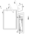
Figure 1 shows a schematic view of a computing system including an adjustable stylus pen in accordance with the principles disclosed herein; -
Figure 2 shows a schematic side partial cross-sectional view of a stylus pen with an adjustable tip in accordance with the principles disclosed herein; -
Figure 3 shows a side view of the extension member of the stylus pen ofFigure 1 in accordance with the principles disclosed herein; -
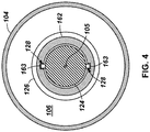
Figure 4 shows a schematic cross-sectional view of the stylus pen along section IV-IV inFigure 2 in accordance with the principles disclosed herein; -
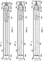
Figures 5-7 show sequential schematic side partial cross-sectional views of the stylus pen ofFigure 1 with the tip being adjusted from a relatively dull shape to a sharper shape in accordance with the principles disclosed herein; and -
Figures 8-10 show enlarged sequential schematic side views of the engagement tip of the stylus pen ofFigure 1 being adjusted from a relatively dull shape to progressively sharper shapes in accordance with the principles disclosed herein. - Certain terms are used throughout the following description and claims to refer to particular system components. As one skilled in the art will appreciate, a single component may be referred to by different names. This document does not intend to distinguish between components that differ in name but not in
function. In the following discussion and in the claims, the terms "including" and "comprising" are used in an open-ended fashion, and thus should be interpreted to mean "including, but not limited to...." Also, the term "couple" or "couples" is intended to mean either an indirect or direct connection. Thus, if a first device couples to a second device, that connection may be through a direct connection, or through an indirect connection via other devices, components, and connections. In addition, as used herein, the terms "axial" and "axially" generally mean along or parallel to a central axis (e.g., central axis of a body or a port), while the terms "radial" and "radially" generally mean perpendicular to the central axis. For instance, an axial distance refers to a distance measured along or parallel to the central axis, and a radial distance means a distance measured perpendicular to the central. - The present invention is set out in the appended set of claims.
- The following discussion is directed to various examples. Although one or more of these examples may be preferred, the examples disclosed should not be interpreted, or otherwise used, as limiting the scope of the disclosure, including the claims. In addition, one skilled in the art will understand that the following description has broad application, and the discussion of any example is meant only to be explanatory of that example, and not intended to intimate that the scope of the disclosure, including the claims, is limited to that example.
- Referring now to
Figure 1 , wherein anexample computing system 10 is shown. In this example,computing system 10 includes acomputing device 20, akeyboard 30, atouchpad 40, and anadjustable stylus pen 100 in accordance with the principles disclosed herein. -
Computing device 20 may comprise any suitable device or assembly of devices that is arranged to execute software, such as, for example, an all-in-one computer, a laptop, a smartphone, a tablet computer, etc. In this example,computing device 20 comprises an all-in-one computer that includes adisplay 22 that shows images thereon for viewing by a user (not shown). In this example,display 22 is touch sensitive. - Keyboard 30 is electrically coupled to computing device 20 (e.g., through a conductor and/or wireless connection) and is arranged such that a user may interact with
computing device 20 by engaging one ormore keys 32 that are disposed thereon.Touch pad 40 is also electrically coupled to computing device (e.g., through a conductor and/or wireless connection) and includes a touchsensitive surface 42. - During operations, a user (not shown) may interact with
computing device 20 by engaging touchsensitive surface 42 oftouch pad 40 and/or display 22 with thestylus pen 100 in order to cause a change withincomputing device 20.Surface 42 anddisplay 22 may each include any suitable touch sensitive technology known in the art while still complying with the principles disclosed herein, such as, for example, resistive, capacitive, acoustic wave, infrared (IR), strain gauge, optical, acoustic pulse recognition, or some combination thereof. - When utilizing
stylus pen 100 to interact with a touch sensitive surface (e.g., display 22 and/or surface 42), it is often desirable to use a wide variety of tip sizes and/or shapes. For example, a user who is running a drawing or drafting program oncomputing device 20 may wish to change the sharpness of the resulting line(s) and/or point(s) produced and shown on thedisplay 22. In many such drafting or drawing programs, such a change may be made through manipulation of various controls within the software itself, a procedure that is often cumbersome and difficult for some users. Thus, various examples ofstylus pen 100 having an adjustable tip are disclosed herein. As will be described in more detail below, through use ofstylus pen 100 in accordance with the principles disclosed herein, a user may simply manipulate an adjustment mechanism disposed on the stylus pen itself to effect a change in the engagement tip size and/or shape and thus the sharpness of the resulting line(s) and/or point(s) shown on the display. Thus, through use of a stylus pen in accordance with the principles disclosed herein (e.g., pen 100), a user's experience is greatly simplified. - Referring now to
Figure 2 , whereinstylus pen 100 is shown.Pen 100 generally includes abody 102, anengagement tip 150, and anadjustment mechanism 120 disposed partially withinbody 102.Body 102 includes an elongate hollow member ortube 104 that further includes a central orlongitudinal axis 105, a first orproximal end 104a, a second ordistal end 104b opposite theproximal end 104a, and acentral throughbore 106 extending axially between theends body 102 is generally sized and formed such that a user may comfortably gripbody 102 with their hand in a manner similar to that of a typical writing pen or pencil. -
Engagement tip 150 is generally disposed at thedistal end 104b oftube 104 and includes afunnel 152, aresilient cover 154, an elongateinternal extension member 160, and a plurality ofinternal guides funnel 152 is generally frustoconical in shape and includes a first orproximal end 152a and a second or distal end 152b opposite theproximal end 152a. In addition,funnel 152 is generally hollow such that it is open at each of theends 152a, 152b.Funnel 152 is coupledbody 102 such thatproximal end 152a abuts or engages thedistal end 104b oftube 104 and distal end 152b extends outwardly therefrom alongaxis 105. -
Resilient cover 154 is mounted to the distal end 152b offunnel 152 such thatcover 154 occludes the opening at the distal end 152b. Cover 154 may comprise any suitable resilient material that may be engaged with a touch sensitive surface while still complying with the principles disclosed herein. In this example, cover 154 comprises a thermoplastic urethane (TPU). -
Guides tube 104, funnel 152, and cover 154 and each includes an open central passage (not shown). As will be described in more detail below, guides 157, 158, 159 are arranged to guide ordirect extension member 160 as it advances axially throughbody 102.Guides body 102 through any suitable method or device while still complying with the principles disclosed herein. For instance, in some examples, funnel 152 and guide 157 are secured to one another such as, for example, through sonic welding or heat staking, and guide 157 is threadably engaged with thedistal end 104b oftube 104. In addition, in these examples, guides 158, 159 are each placed withinfunnel 152 such that each may slide or translate axially relative to funnel 152 and guide 157 during operations. It should also be appreciated that in some examples, one or more of theguides pen 100 while still complying with the principles disclosed herein. - Referring now to
Figure 3 ,extension member 160 generally includes a central orlongitudinal axis 165 that is aligned with theaxis 105 ofpen 100 when fully inserted therein, a first orproximal end 160a, a second ordistal end 160b opposite theproximal end 160b, abarrel section 162 extending axially from theproximal end 160a, anextension section 166 extending axially from thedistal end 160a, and aconnection section 164 extending axially from thebarrel section 162 to theextension section 166. -
Barrel section 162 includes a radiallyouter surface 162a and arecess 168 extending axially from theproximal end 160a that is substantially defined by a radiallyinner surface 162b. In this example,surfaces surfaces barrel section 162 also includes agroove 161 that extends radially inward from the radiallyouter surface 162a and wraps helically aboutsection 162. Thus, groove 161 may be referred to herein as "helical groove" 161. Further, in this example,recess 168 includes a pair of axially orientedgrooves 163 which extend radially outward from thesurface 162b. - In this example,
connection section 164 is generally cylindrical in shape and extends axially between thebarrel section 162 andextension section 166. In other examples,connection member 164 may be formed in a number of different shapes, such as, for example, rectangular, pentagonal, hexagonal, octagonal, polygonal, or some combination thereof. In addition, it should also be appreciated that in some examples, noconnection member 164 is included while still complying with the principles disclosed herein. - Referring still to
Figure 3 ,extension member 166 is an elongate member having a tip or end 169 disposed at thedistal end 160b ofmember 160. As will be explained in more detail below, asextension member 160 translates axially withintube 104, end 169 ofsection 166 engages withcover 154 to change the shape ofcover 154 from dull to relatively sharp. - Referring back now to
Figure 2 ,adjustment mechanism 120 includes auser interaction mechanism 122, anelongate rod 124 extending intothroughbore 106 frommechanism 122, and acoil 126 disposed withinthroughbore 106.Interaction mechanism 122 may include any suitable mechanism for interaction with a user during use of thepen 100 while still complying with the principles disclosed herein. For example, in this example,mechanism 122 comprises a knob that is rotatably coupled to theproximal end 104a oftube 104 such thatknob 122 may rotate or pivot about theaxis 105 during operation. Accordingly, in the description to follow,user interaction mechanism 122 may also be referred to asknob 122. -
Rod 124 includes a first orproximal end 124a and a second ordistal end 124b opposite theproximal end 124a.Proximal end 124a is mounted toknob 122 such that asknob 122 rotates aboutaxis 105,rod 124 also rotates aboutaxis 105. In addition, thedistal end 124b ofrod 124 is slidingly received within therecess 168 ofbarrel section 162 ofextension member 160. In at least some examples,end 124b ofrod 124 is received withinrecess 168 such thatmember 160 is driven to rotate along withrod 124 andknob 122 aboutaxis 105 while still allowingmember 160 to translate axially relative torod 124 with respect toaxis 105. For instance, in this example, as is best shown inFigure 4 ,rod 124 includes a pair ofradial projections 128 that extend axially from or proximatedistal end 124b such that whenrod 124 is inserted withinrecess 168, theprojections 128 each slidingly engage one of therecesses 163 to fix the relative angular positions ofrod 124 andmember 160. - Referring again to
Figure 2 ,coil 126 is wire-like structure that is secured withinthroughbore 106 oftube 104 and includes a first orproximal end 126a, a second ordistal end 126b opposite theproximal end 126a, and abody 126c extending helically between theend axis 105. In this example,coil 126 is secured withinthroughbore 106 such that its angular position with respect to theaxis 105 is substantially fixed. Any suitable device or method for fixingcoil 126 withinthroughbore 106 may be used while still complying with the principles disclosed herein. In addition, in this example, thehelical body 126c ofcoil 126 is shaped and sized to correspond with thehelical groove 161 on the barrel section 162 (seeFigure 3 ) ofextension member 160. - Referring now to
Figures 2-4 , during assembly ofstylus pen 100,extension member 160 is inserted withinthroughbore 106 oftube 104 such that theend 169 ofengagement section 166 extends through each of theguides proximate cover 154. In addition, asextension member 160 is installed withinthroughbore 106 in the manner described, thebody 126c ofcoil 126 engages thegroove 163 onbarrel section 162. Thereafter,rod 124 is inserted withinthroughbore 106 from theproximal end 104a such that thedistal end 124b ofrod 124 is inserted withinrecess 168 andprojections 128 slidingly engage therecesses 161 in the manner described above (seeFigure 4 ). Thus, due to the engagement ofcoil 126 withgroove 161, whenextension member 160 rotates about theaxis 105 along a direction 127 (seeFigure 2 ),body 126c slidingly engages with thegroove 161 onmember 160 and thus urgesmember 160 axially toward thedistal end 104a (or to the right as shown inFigure 2 ). Similarly, whenextension member 160 is rotated aboutaxis 105 in a direction that isopposite direction 127,body 126c oncoil 126 urgesmember 160 axially toward theproximal end 104a (or to the left as shown inFigure 2 ). In addition,knob 122 is coupled toproximal end 124a in the manner previously described such that each of theknob 122 androd 124 are arranged to rotate in unison with one another about theaxis 105 during operation. - Referring now to
Figures 2 and5-7 , a user (not shown) may rotateknob 122 about theaxis 105 in thedirection 127. Asknob 122 is rotated about theaxis 105 indirection 127,rod 124 and extension member 160 (e.g., due to the engagement of theprojections 128 onrod 124 and therecesses 163 within therecess 168 of extension member 160) each also rotate aboutaxis 105 along thedirection 127. Asextension member 160 rotates indirection 127,body 126c ofcoil 126 slidingly engages withgroove 161 onmember 160 and urgesmember 160 axially towarddistal end 104b and cover 154 in the manner previously described (see progression fromFigure 5 to Figure 7 ). To axially withdrawnextension member 160 withintube 104,knob 122,rod 124, and thusextension member 160 are all rotated about theaxis 105 in a direction that is opposite thedirection 127 such thatcoil 126 urgesextension member 160 toward theproximal end 104a (see the progression fromFigure 7 to Figure 5 ). As is shown inFigures 5-7 , asmember 160 is axially moved toward thedistal end 104b oftube 104, theend 169 ofmember 160 engages with and thereby deformscover 154. Ascover 154 is deformed, it changes shape from more dull (e.g.,Figure 5 ) to progressively more sharp (e.g.,Figures 6 and 7 ). As a result,engagement tip 150 ofpen 100 is actuatable between a plurality of positions wherein the shape oftip 150 is different at each position. In particular,pen 100 is actuatable, through manipulation ofadjustment mechanism 120, between a plurality of positions wherein the shape of theengagement tip 150 ranges from dull to sharp. - In addition, as
engagement tip 150 ofpen 100 is actuated between relatively dull shapes to a relative sharp shapes, the axial length oftip 150 increases. In particular, as shown inFigure 5 , whentip 150 is in an initial position corresponding to a relatively dull shape,tip 150 has an axial length L150A measured axially from theproximal end 152a offunnel 152 to the distal most point ofcover 154. Next, as shown inFigure 6 , astip 150 is transitioned to a position corresponding to a relatively sharper shape, thetip 150 has an axial length L150B that is greater than the axial length L150A shown inFigure 5 . Similarly, astip 150 is actuated to positions with progressively sharper shapes, such as is shown inFigure 7 , tip has an axial length L150c that is greater than each of the axial lengths L150A, L150B shown inFigures 5 and 6 , respectively. - Referring now to
Figures 5-10 , during use ofpen 100 by a user,cover 154 ontip 150 is directly engaged with a touch sensitive surface 180 (e.g., touchsensitive display 22 orsurface 42 of touch pad 40) with a portion of the total surface area ofcover 154 that is referred to herein as an engagement surface or area 170 (SeeFigures 8-10 ). In other words, theengagement area 170 ofcover 154 refers to the specific fractional portion of the outer surface ofcover 154 that physically engages with the touchsensitive surface 180 during use ofpen 100. In general, asmember 160 is axially advanced throughtube 104 such thatcover 154 is deformed to form a sharper shape, theengagement area 170 between thecover 154 and the touchsensitive surface 180 necessarily decreases in size. In particular, as best shown inFigures 8-10 , asengagement tip 150 is transitioned from a dull point (e.g.,Figure 8 ) to a relative sharp point (e.g.,Figure 10 ) theengagement area 170 contacting the touch sensitive surface (e.g.,surface 180 shown inFigures 5-7 ) decreases in size. Thus, a user may manipulate theadjustment mechanism 120 ofpen 100 to achieve a variety of relatively fine and dull shapes for engagement with the touch sensitive surface. - In the manner described, through use of a stylus pen in accordance with the principles disclosed herein (e.g., pen 100), a user may simply manipulate an adjustment mechanism (e.g., mechanism 120) disposed on the stylus pen itself to affect a change in the engagement tip shape (e.g., tip 150), thereby also affecting a change in the sharpness of the resulting line(s) and/or point(s) shown on the display (e.g., display 22) of the associated computing device (e.g., device 20). As a result, a user may affect such a change in the line(s) and/or point(s) shown on the display without needing to make cumbersome and difficult changes through the specific software being used such that the user's experience is greatly simplified.
- While examples disclosed herein have included an
extension member 160 that includes acylindrical recess 168 that receives thedistal end 124b of a substantiallycylindrical rod 124, it should be appreciated that in other examples,rod 124 andrecess 168 may each be formed in other corresponding shapes, such as, for example, rectangular, pentagonal, hexagonal, octagonal, polygonal, or some combination thereof. In addition, in at least some of these examples,recess 168 does not include therecesses 163 androd 124 does not includeprojections 128 while still complying with the principles disclosed herein. Further, while examples disclosed herein have included anadjustment mechanism 120 that includes arotatable knob 122, it should be appreciated that other types of adjustment mechanisms may be used to axially advance or withdrawn theextension member 160 relative totube 104 while still complying with the principles disclosed herein. For instance, in some examples,adjustment mechanism 120 may comprise a button that is depressed to axiallyadvance extension member 160 through an internal ratcheting system. - The above discussion is meant to be illustrative of the principles and various embodiments of the present disclosure. Numerous variations and modifications will become apparent to those skilled in the art.
Claims (8)
- A stylus pen (100) comprising:a body (102) including a central axis (105), a first end (104a), and a second end (104b);an engagement tip (150) disposed at the first end and including resilient cover (154); characterised in that:the engagement tip comprises an elongate extension member (160) that is axially movable relative to the body, wherein the resilient cover is disposed over the extension member; andthe stylus pen further comprises an adjustment mechanism (120) at least partially disposed within the body and arranged such that manipulation of the adjustment mechanism by a user causes the extension member to move axially relative to the body, and the cover of the engagement tip to actuate between a first shape and a second shape;wherein the cover of the engagement tip is arranged to engage with a touch sensitive surface to cause a change in a computing device when in either one of the first shape and the second shape.
- The stylus pen of claim 1, wherein the adjustment mechanism includes a knob rotatably disposed at the second end of the body, wherein rotation of the knob causes the cover of the engagement tip to actuate between the first shape and the second shape.
- The stylus pen of claim 1,
wherein the first shape has a first engagement area when the tip is engaged with a touch sensitive surface;
wherein the second shape has a second engagement area when the tip is engaged with the touch sensitive surface; and
wherein the first engagement area is larger than the second engagement area. - The stylus pen of claim 1, wherein the engagement tip has an axial length and wherein the axial length is increased when the cover of the engagement tip is actuated from the first shape to the second shape.
- A computing system (10), comprising:a touch sensitive surface (42);a display (22); andthe stylus of claim 1;wherein the first shape of the engagement tip is sharper than the second shape of the engament tip; andwherein the engagement tip is arranged to engage with the touch sensitive surface to cause a change on the display when in either one of the first shape and the second shape.
- The computing system of claim 5, wherein the engagement tip is actuatable between the first shape and the second shape with an adjustment mechanism that is at least partially disposed within the body.
- The computing system of claim 6, wherein the adjustment mechanism includes a knob rotatably disposed at the second end of the body, wherein rotation of the knob causes the engagement tip to actuate between the first shape and the second shape.
- The computing system of claim 5, wherein the engagement tip has an axial length and wherein actuation of the engagement tip from the first shape to the second shape causes the axial length to increase.
Applications Claiming Priority (1)
| Application Number | Priority Date | Filing Date | Title |
|---|---|---|---|
| PCT/US2014/013726 WO2015116074A1 (en) | 2014-01-30 | 2014-01-30 | Adjustable stylus pen |
Publications (3)
| Publication Number | Publication Date |
|---|---|
| EP3100141A1 EP3100141A1 (en) | 2016-12-07 |
| EP3100141A4 EP3100141A4 (en) | 2017-09-06 |
| EP3100141B1 true EP3100141B1 (en) | 2018-11-14 |
Family
ID=53757484
Family Applications (1)
| Application Number | Title | Priority Date | Filing Date |
|---|---|---|---|
| EP14881181.3A Not-in-force EP3100141B1 (en) | 2014-01-30 | 2014-01-30 | Adjustable stylus pen |
Country Status (4)
| Country | Link |
|---|---|
| US (2) | US20160364028A1 (en) |
| EP (1) | EP3100141B1 (en) |
| CN (1) | CN105934731B (en) |
| WO (1) | WO2015116074A1 (en) |
Families Citing this family (4)
| Publication number | Priority date | Publication date | Assignee | Title |
|---|---|---|---|---|
| KR102355459B1 (en) * | 2015-08-11 | 2022-01-26 | 삼성전자주식회사 | Stylus pen and electronics apparatus having the same |
| US10073544B2 (en) | 2015-10-14 | 2018-09-11 | Microsoft Technology Licensing, Llc | Stylus with adjustable grip diameter |
| US10185409B2 (en) | 2016-03-15 | 2019-01-22 | Microsoft Technology Licensing, Llc | Stylus with an adjustable dimension |
| KR102488305B1 (en) * | 2018-06-11 | 2023-01-13 | 삼성전자주식회사 | Input device and electronic device with the same |
Family Cites Families (26)
| Publication number | Priority date | Publication date | Assignee | Title |
|---|---|---|---|---|
| US6259438B1 (en) * | 1998-06-04 | 2001-07-10 | Wacom Co., Ltd. | Coordinate input stylus |
| JPH08137602A (en) | 1994-11-09 | 1996-05-31 | Alps Electric Co Ltd | Stylus pen |
| JPH096518A (en) | 1995-06-16 | 1997-01-10 | Wacom Co Ltd | Side switch mechanism and stylus pen |
| JP3192349B2 (en) | 1995-06-19 | 2001-07-23 | シャープ株式会社 | Touch input pen |
| US6130666A (en) | 1996-10-07 | 2000-10-10 | Persidsky; Andre | Self-contained pen computer with built-in display |
| JP3327879B2 (en) | 1999-10-14 | 2002-09-24 | ゼブラ株式会社 | Knock-type writing instrument |
| US6882340B2 (en) | 2001-10-19 | 2005-04-19 | Wacom Co., Ltd. | Electronic pen |
| US20070189832A1 (en) * | 2006-02-10 | 2007-08-16 | Ta Hsing Electric Wire & Cable Co., Ltd. | Control button assembly for mechanical pen |
| US8842099B2 (en) * | 2007-12-14 | 2014-09-23 | Songtak Technology Co., Ltd. | Touch pen structure |
| US20090309854A1 (en) * | 2008-06-13 | 2009-12-17 | Polyvision Corporation | Input devices with multiple operating modes |
| KR20100027255A (en) * | 2008-09-02 | 2010-03-11 | 주식회사 미성포리테크 | Carrying terminal for stylus pen structure |
| KR20100082409A (en) * | 2009-01-09 | 2010-07-19 | (주)쉘라인 | Stylus pen |
| US8493340B2 (en) * | 2009-01-16 | 2013-07-23 | Corel Corporation | Virtual hard media imaging |
| US8482539B2 (en) | 2010-01-12 | 2013-07-09 | Panasonic Corporation | Electronic pen system |
| US9110534B2 (en) | 2010-05-04 | 2015-08-18 | Google Technology Holdings LLC | Stylus devices having variable electrical characteristics for capacitive touchscreens |
| US20120146957A1 (en) * | 2010-12-09 | 2012-06-14 | Kelly Allan Dunagan | Stylus tip device for touch screen |
| WO2012103323A1 (en) * | 2011-01-28 | 2012-08-02 | More/Real Llc | Stylus |
| US8847930B2 (en) * | 2011-04-17 | 2014-09-30 | Wimo Labs LLC | Electrically conductive touch pen |
| US9329703B2 (en) | 2011-06-22 | 2016-05-03 | Apple Inc. | Intelligent stylus |
| TWI447614B (en) * | 2011-12-02 | 2014-08-01 | Asustek Comp Inc | Stylus |
| KR101999119B1 (en) * | 2012-07-11 | 2019-07-12 | 삼성전자 주식회사 | Method using pen input device and terminal thereof |
| US20140015810A1 (en) * | 2012-07-16 | 2014-01-16 | Jack Chau | Compact conductive stylus |
| US9690394B2 (en) | 2012-09-14 | 2017-06-27 | Apple Inc. | Input device having extendable nib |
| CN103440051B (en) * | 2013-07-26 | 2017-06-27 | 张晶 | Stylus |
| JP5732600B1 (en) * | 2013-08-03 | 2015-06-10 | 株式会社ワコム | Position indicator |
| US9671877B2 (en) | 2014-01-27 | 2017-06-06 | Nvidia Corporation | Stylus tool with deformable tip |
-
2014
- 2014-01-30 EP EP14881181.3A patent/EP3100141B1/en not_active Not-in-force
- 2014-01-30 US US15/114,060 patent/US20160364028A1/en not_active Abandoned
- 2014-01-30 WO PCT/US2014/013726 patent/WO2015116074A1/en not_active Ceased
- 2014-01-30 CN CN201480074571.8A patent/CN105934731B/en not_active Expired - Fee Related
-
2019
- 2019-03-04 US US16/291,378 patent/US10852850B2/en not_active Expired - Fee Related
Non-Patent Citations (1)
| Title |
|---|
| None * |
Also Published As
| Publication number | Publication date |
|---|---|
| EP3100141A4 (en) | 2017-09-06 |
| CN105934731A (en) | 2016-09-07 |
| CN105934731B (en) | 2019-07-23 |
| US20160364028A1 (en) | 2016-12-15 |
| WO2015116074A1 (en) | 2015-08-06 |
| EP3100141A1 (en) | 2016-12-07 |
| US10852850B2 (en) | 2020-12-01 |
| US20190196611A1 (en) | 2019-06-27 |
Similar Documents
| Publication | Publication Date | Title |
|---|---|---|
| US10852850B2 (en) | Adjustable stylus pen | |
| US11353969B2 (en) | Dynamic visual indications for input devices | |
| US9092077B2 (en) | Writing device having writing tip and stylus tip | |
| EP1869541B1 (en) | Computer mouse peripheral | |
| KR101364837B1 (en) | Adaptive Virtual Keyboard for Handheld Devices | |
| CN108345396B (en) | Touch pen with magnetic induction wheel and operation method thereof | |
| EP2450782A1 (en) | Adaptive virtual keyboard for handheld device | |
| EP3101512B1 (en) | Touch pen with haptic feedback | |
| US20130234967A1 (en) | Pressure sensitive multi-tip stylus for capacitive touchscreens and methods of using same | |
| CN103003779A (en) | touch input device | |
| CN204483154U (en) | a glove | |
| JP5995475B2 (en) | Rotating payout writing instrument | |
| CN101339469A (en) | Mouse (Saggar) | |
| US6341911B1 (en) | Writing instrument with adjustable shaft | |
| JP5806516B2 (en) | Input pen | |
| CN2480905Y (en) | Stylus for Personal Digital Mobile Devices | |
| JP2013125415A (en) | Input pen | |
| JP3083103U (en) | stylus | |
| CN201556174U (en) | pointing device | |
| US20090091533A1 (en) | Keyboard | |
| TWM460334U (en) | Brush touch pen with rotatable retractile mechanism | |
| JP2000343871A (en) | Writing instrument grip | |
| JP2017151615A (en) | Stick-type input device | |
| JP2014127153A (en) | Input pen | |
| JP2014191819A (en) | Fingertip function assistance device for touch panel input |
Legal Events
| Date | Code | Title | Description |
|---|---|---|---|
| PUAI | Public reference made under article 153(3) epc to a published international application that has entered the european phase |
Free format text: ORIGINAL CODE: 0009012 |
|
| STAA | Information on the status of an ep patent application or granted ep patent |
Free format text: STATUS: REQUEST FOR EXAMINATION WAS MADE |
|
| 17P | Request for examination filed |
Effective date: 20160608 |
|
| AK | Designated contracting states |
Kind code of ref document: A1 Designated state(s): AL AT BE BG CH CY CZ DE DK EE ES FI FR GB GR HR HU IE IS IT LI LT LU LV MC MK MT NL NO PL PT RO RS SE SI SK SM TR |
|
| AX | Request for extension of the european patent |
Extension state: BA ME |
|
| DAX | Request for extension of the european patent (deleted) | ||
| RIC1 | Information provided on ipc code assigned before grant |
Ipc: G06F 3/033 20130101AFI20170622BHEP |
|
| A4 | Supplementary search report drawn up and despatched |
Effective date: 20170803 |
|
| RIC1 | Information provided on ipc code assigned before grant |
Ipc: G06F 3/033 20130101AFI20170728BHEP |
|
| GRAP | Despatch of communication of intention to grant a patent |
Free format text: ORIGINAL CODE: EPIDOSNIGR1 |
|
| STAA | Information on the status of an ep patent application or granted ep patent |
Free format text: STATUS: GRANT OF PATENT IS INTENDED |
|
| INTG | Intention to grant announced |
Effective date: 20180523 |
|
| GRAS | Grant fee paid |
Free format text: ORIGINAL CODE: EPIDOSNIGR3 |
|
| GRAA | (expected) grant |
Free format text: ORIGINAL CODE: 0009210 |
|
| STAA | Information on the status of an ep patent application or granted ep patent |
Free format text: STATUS: THE PATENT HAS BEEN GRANTED |
|
| AK | Designated contracting states |
Kind code of ref document: B1 Designated state(s): AL AT BE BG CH CY CZ DE DK EE ES FI FR GB GR HR HU IE IS IT LI LT LU LV MC MK MT NL NO PL PT RO RS SE SI SK SM TR |
|
| REG | Reference to a national code |
Ref country code: CH Ref legal event code: EP Ref country code: AT Ref legal event code: REF Ref document number: 1065590 Country of ref document: AT Kind code of ref document: T Effective date: 20181115 |
|
| REG | Reference to a national code |
Ref country code: DE Ref legal event code: R096 Ref document number: 602014036267 Country of ref document: DE |
|
| REG | Reference to a national code |
Ref country code: IE Ref legal event code: FG4D |
|
| REG | Reference to a national code |
Ref country code: NL Ref legal event code: MP Effective date: 20181114 |
|
| REG | Reference to a national code |
Ref country code: LT Ref legal event code: MG4D |
|
| REG | Reference to a national code |
Ref country code: AT Ref legal event code: MK05 Ref document number: 1065590 Country of ref document: AT Kind code of ref document: T Effective date: 20181114 |
|
| PG25 | Lapsed in a contracting state [announced via postgrant information from national office to epo] |
Ref country code: FI Free format text: LAPSE BECAUSE OF FAILURE TO SUBMIT A TRANSLATION OF THE DESCRIPTION OR TO PAY THE FEE WITHIN THE PRESCRIBED TIME-LIMIT Effective date: 20181114 Ref country code: IS Free format text: LAPSE BECAUSE OF FAILURE TO SUBMIT A TRANSLATION OF THE DESCRIPTION OR TO PAY THE FEE WITHIN THE PRESCRIBED TIME-LIMIT Effective date: 20190314 Ref country code: NO Free format text: LAPSE BECAUSE OF FAILURE TO SUBMIT A TRANSLATION OF THE DESCRIPTION OR TO PAY THE FEE WITHIN THE PRESCRIBED TIME-LIMIT Effective date: 20190214 Ref country code: AT Free format text: LAPSE BECAUSE OF FAILURE TO SUBMIT A TRANSLATION OF THE DESCRIPTION OR TO PAY THE FEE WITHIN THE PRESCRIBED TIME-LIMIT Effective date: 20181114 Ref country code: LV Free format text: LAPSE BECAUSE OF FAILURE TO SUBMIT A TRANSLATION OF THE DESCRIPTION OR TO PAY THE FEE WITHIN THE PRESCRIBED TIME-LIMIT Effective date: 20181114 Ref country code: LT Free format text: LAPSE BECAUSE OF FAILURE TO SUBMIT A TRANSLATION OF THE DESCRIPTION OR TO PAY THE FEE WITHIN THE PRESCRIBED TIME-LIMIT Effective date: 20181114 Ref country code: ES Free format text: LAPSE BECAUSE OF FAILURE TO SUBMIT A TRANSLATION OF THE DESCRIPTION OR TO PAY THE FEE WITHIN THE PRESCRIBED TIME-LIMIT Effective date: 20181114 Ref country code: BG Free format text: LAPSE BECAUSE OF FAILURE TO SUBMIT A TRANSLATION OF THE DESCRIPTION OR TO PAY THE FEE WITHIN THE PRESCRIBED TIME-LIMIT Effective date: 20190214 Ref country code: HR Free format text: LAPSE BECAUSE OF FAILURE TO SUBMIT A TRANSLATION OF THE DESCRIPTION OR TO PAY THE FEE WITHIN THE PRESCRIBED TIME-LIMIT Effective date: 20181114 |
|
| RAP2 | Party data changed (patent owner data changed or rights of a patent transferred) |
Owner name: HEWLETT-PACKARD DEVELOPMENT COMPANY, L.P. |
|
| PG25 | Lapsed in a contracting state [announced via postgrant information from national office to epo] |
Ref country code: PT Free format text: LAPSE BECAUSE OF FAILURE TO SUBMIT A TRANSLATION OF THE DESCRIPTION OR TO PAY THE FEE WITHIN THE PRESCRIBED TIME-LIMIT Effective date: 20190314 Ref country code: AL Free format text: LAPSE BECAUSE OF FAILURE TO SUBMIT A TRANSLATION OF THE DESCRIPTION OR TO PAY THE FEE WITHIN THE PRESCRIBED TIME-LIMIT Effective date: 20181114 Ref country code: SE Free format text: LAPSE BECAUSE OF FAILURE TO SUBMIT A TRANSLATION OF THE DESCRIPTION OR TO PAY THE FEE WITHIN THE PRESCRIBED TIME-LIMIT Effective date: 20181114 Ref country code: GR Free format text: LAPSE BECAUSE OF FAILURE TO SUBMIT A TRANSLATION OF THE DESCRIPTION OR TO PAY THE FEE WITHIN THE PRESCRIBED TIME-LIMIT Effective date: 20190215 Ref country code: RS Free format text: LAPSE BECAUSE OF FAILURE TO SUBMIT A TRANSLATION OF THE DESCRIPTION OR TO PAY THE FEE WITHIN THE PRESCRIBED TIME-LIMIT Effective date: 20181114 Ref country code: NL Free format text: LAPSE BECAUSE OF FAILURE TO SUBMIT A TRANSLATION OF THE DESCRIPTION OR TO PAY THE FEE WITHIN THE PRESCRIBED TIME-LIMIT Effective date: 20181114 |
|
| PG25 | Lapsed in a contracting state [announced via postgrant information from national office to epo] |
Ref country code: IT Free format text: LAPSE BECAUSE OF FAILURE TO SUBMIT A TRANSLATION OF THE DESCRIPTION OR TO PAY THE FEE WITHIN THE PRESCRIBED TIME-LIMIT Effective date: 20181114 Ref country code: CZ Free format text: LAPSE BECAUSE OF FAILURE TO SUBMIT A TRANSLATION OF THE DESCRIPTION OR TO PAY THE FEE WITHIN THE PRESCRIBED TIME-LIMIT Effective date: 20181114 Ref country code: PL Free format text: LAPSE BECAUSE OF FAILURE TO SUBMIT A TRANSLATION OF THE DESCRIPTION OR TO PAY THE FEE WITHIN THE PRESCRIBED TIME-LIMIT Effective date: 20181114 Ref country code: DK Free format text: LAPSE BECAUSE OF FAILURE TO SUBMIT A TRANSLATION OF THE DESCRIPTION OR TO PAY THE FEE WITHIN THE PRESCRIBED TIME-LIMIT Effective date: 20181114 |
|
| REG | Reference to a national code |
Ref country code: DE Ref legal event code: R097 Ref document number: 602014036267 Country of ref document: DE |
|
| PG25 | Lapsed in a contracting state [announced via postgrant information from national office to epo] |
Ref country code: SM Free format text: LAPSE BECAUSE OF FAILURE TO SUBMIT A TRANSLATION OF THE DESCRIPTION OR TO PAY THE FEE WITHIN THE PRESCRIBED TIME-LIMIT Effective date: 20181114 Ref country code: EE Free format text: LAPSE BECAUSE OF FAILURE TO SUBMIT A TRANSLATION OF THE DESCRIPTION OR TO PAY THE FEE WITHIN THE PRESCRIBED TIME-LIMIT Effective date: 20181114 Ref country code: RO Free format text: LAPSE BECAUSE OF FAILURE TO SUBMIT A TRANSLATION OF THE DESCRIPTION OR TO PAY THE FEE WITHIN THE PRESCRIBED TIME-LIMIT Effective date: 20181114 Ref country code: MC Free format text: LAPSE BECAUSE OF FAILURE TO SUBMIT A TRANSLATION OF THE DESCRIPTION OR TO PAY THE FEE WITHIN THE PRESCRIBED TIME-LIMIT Effective date: 20181114 Ref country code: SK Free format text: LAPSE BECAUSE OF FAILURE TO SUBMIT A TRANSLATION OF THE DESCRIPTION OR TO PAY THE FEE WITHIN THE PRESCRIBED TIME-LIMIT Effective date: 20181114 |
|
| REG | Reference to a national code |
Ref country code: CH Ref legal event code: PL |
|
| PLBE | No opposition filed within time limit |
Free format text: ORIGINAL CODE: 0009261 |
|
| STAA | Information on the status of an ep patent application or granted ep patent |
Free format text: STATUS: NO OPPOSITION FILED WITHIN TIME LIMIT |
|
| PG25 | Lapsed in a contracting state [announced via postgrant information from national office to epo] |
Ref country code: LU Free format text: LAPSE BECAUSE OF NON-PAYMENT OF DUE FEES Effective date: 20190130 |
|
| REG | Reference to a national code |
Ref country code: BE Ref legal event code: MM Effective date: 20190131 |
|
| 26N | No opposition filed |
Effective date: 20190815 |
|
| REG | Reference to a national code |
Ref country code: IE Ref legal event code: MM4A |
|
| PG25 | Lapsed in a contracting state [announced via postgrant information from national office to epo] |
Ref country code: SI Free format text: LAPSE BECAUSE OF FAILURE TO SUBMIT A TRANSLATION OF THE DESCRIPTION OR TO PAY THE FEE WITHIN THE PRESCRIBED TIME-LIMIT Effective date: 20181114 |
|
| PG25 | Lapsed in a contracting state [announced via postgrant information from national office to epo] |
Ref country code: BE Free format text: LAPSE BECAUSE OF NON-PAYMENT OF DUE FEES Effective date: 20190131 |
|
| PG25 | Lapsed in a contracting state [announced via postgrant information from national office to epo] |
Ref country code: CH Free format text: LAPSE BECAUSE OF NON-PAYMENT OF DUE FEES Effective date: 20190131 Ref country code: LI Free format text: LAPSE BECAUSE OF NON-PAYMENT OF DUE FEES Effective date: 20190131 |
|
| PG25 | Lapsed in a contracting state [announced via postgrant information from national office to epo] |
Ref country code: IE Free format text: LAPSE BECAUSE OF NON-PAYMENT OF DUE FEES Effective date: 20190130 |
|
| PG25 | Lapsed in a contracting state [announced via postgrant information from national office to epo] |
Ref country code: TR Free format text: LAPSE BECAUSE OF FAILURE TO SUBMIT A TRANSLATION OF THE DESCRIPTION OR TO PAY THE FEE WITHIN THE PRESCRIBED TIME-LIMIT Effective date: 20181114 |
|
| PG25 | Lapsed in a contracting state [announced via postgrant information from national office to epo] |
Ref country code: MT Free format text: LAPSE BECAUSE OF NON-PAYMENT OF DUE FEES Effective date: 20190130 |
|
| PG25 | Lapsed in a contracting state [announced via postgrant information from national office to epo] |
Ref country code: CY Free format text: LAPSE BECAUSE OF FAILURE TO SUBMIT A TRANSLATION OF THE DESCRIPTION OR TO PAY THE FEE WITHIN THE PRESCRIBED TIME-LIMIT Effective date: 20181114 |
|
| PG25 | Lapsed in a contracting state [announced via postgrant information from national office to epo] |
Ref country code: HU Free format text: LAPSE BECAUSE OF FAILURE TO SUBMIT A TRANSLATION OF THE DESCRIPTION OR TO PAY THE FEE WITHIN THE PRESCRIBED TIME-LIMIT; INVALID AB INITIO Effective date: 20140130 |
|
| PGFP | Annual fee paid to national office [announced via postgrant information from national office to epo] |
Ref country code: GB Payment date: 20211216 Year of fee payment: 9 Ref country code: FR Payment date: 20211215 Year of fee payment: 9 |
|
| PGFP | Annual fee paid to national office [announced via postgrant information from national office to epo] |
Ref country code: DE Payment date: 20211215 Year of fee payment: 9 |
|
| PG25 | Lapsed in a contracting state [announced via postgrant information from national office to epo] |
Ref country code: MK Free format text: LAPSE BECAUSE OF FAILURE TO SUBMIT A TRANSLATION OF THE DESCRIPTION OR TO PAY THE FEE WITHIN THE PRESCRIBED TIME-LIMIT Effective date: 20181114 |
|
| REG | Reference to a national code |
Ref country code: DE Ref legal event code: R119 Ref document number: 602014036267 Country of ref document: DE |
|
| GBPC | Gb: european patent ceased through non-payment of renewal fee |
Effective date: 20230130 |
|
| PG25 | Lapsed in a contracting state [announced via postgrant information from national office to epo] |
Ref country code: GB Free format text: LAPSE BECAUSE OF NON-PAYMENT OF DUE FEES Effective date: 20230130 Ref country code: DE Free format text: LAPSE BECAUSE OF NON-PAYMENT OF DUE FEES Effective date: 20230801 |
|
| PG25 | Lapsed in a contracting state [announced via postgrant information from national office to epo] |
Ref country code: FR Free format text: LAPSE BECAUSE OF NON-PAYMENT OF DUE FEES Effective date: 20230131 |