EP3099355B1 - Therapeutic product delivery device - Google Patents
Therapeutic product delivery device Download PDFInfo
- Publication number
- EP3099355B1 EP3099355B1 EP15708021.9A EP15708021A EP3099355B1 EP 3099355 B1 EP3099355 B1 EP 3099355B1 EP 15708021 A EP15708021 A EP 15708021A EP 3099355 B1 EP3099355 B1 EP 3099355B1
- Authority
- EP
- European Patent Office
- Prior art keywords
- cartridge
- therapeutic product
- delivery device
- device body
- product delivery
- Prior art date
- Legal status (The legal status is an assumption and is not a legal conclusion. Google has not performed a legal analysis and makes no representation as to the accuracy of the status listed.)
- Active
Links
- 230000001225 therapeutic effect Effects 0.000 title claims description 27
- 238000005086 pumping Methods 0.000 claims description 20
- 238000001514 detection method Methods 0.000 claims description 10
- 238000006073 displacement reaction Methods 0.000 claims description 7
- 230000004044 response Effects 0.000 claims description 6
- NOESYZHRGYRDHS-UHFFFAOYSA-N insulin Chemical compound N1C(=O)C(NC(=O)C(CCC(N)=O)NC(=O)C(CCC(O)=O)NC(=O)C(C(C)C)NC(=O)C(NC(=O)CN)C(C)CC)CSSCC(C(NC(CO)C(=O)NC(CC(C)C)C(=O)NC(CC=2C=CC(O)=CC=2)C(=O)NC(CCC(N)=O)C(=O)NC(CC(C)C)C(=O)NC(CCC(O)=O)C(=O)NC(CC(N)=O)C(=O)NC(CC=2C=CC(O)=CC=2)C(=O)NC(CSSCC(NC(=O)C(C(C)C)NC(=O)C(CC(C)C)NC(=O)C(CC=2C=CC(O)=CC=2)NC(=O)C(CC(C)C)NC(=O)C(C)NC(=O)C(CCC(O)=O)NC(=O)C(C(C)C)NC(=O)C(CC(C)C)NC(=O)C(CC=2NC=NC=2)NC(=O)C(CO)NC(=O)CNC2=O)C(=O)NCC(=O)NC(CCC(O)=O)C(=O)NC(CCCNC(N)=N)C(=O)NCC(=O)NC(CC=3C=CC=CC=3)C(=O)NC(CC=3C=CC=CC=3)C(=O)NC(CC=3C=CC(O)=CC=3)C(=O)NC(C(C)O)C(=O)N3C(CCC3)C(=O)NC(CCCCN)C(=O)NC(C)C(O)=O)C(=O)NC(CC(N)=O)C(O)=O)=O)NC(=O)C(C(C)CC)NC(=O)C(CO)NC(=O)C(C(C)O)NC(=O)C1CSSCC2NC(=O)C(CC(C)C)NC(=O)C(NC(=O)C(CCC(N)=O)NC(=O)C(CC(N)=O)NC(=O)C(NC(=O)C(N)CC=1C=CC=CC=1)C(C)C)CC1=CN=CN1 NOESYZHRGYRDHS-UHFFFAOYSA-N 0.000 description 90
- 102000004877 Insulin Human genes 0.000 description 45
- 108090001061 Insulin Proteins 0.000 description 45
- 229940125396 insulin Drugs 0.000 description 45
- 239000008280 blood Substances 0.000 description 18
- 210000004369 blood Anatomy 0.000 description 18
- WQZGKKKJIJFFOK-GASJEMHNSA-N Glucose Natural products OC[C@H]1OC(O)[C@H](O)[C@@H](O)[C@@H]1O WQZGKKKJIJFFOK-GASJEMHNSA-N 0.000 description 13
- 239000008103 glucose Substances 0.000 description 13
- 230000000694 effects Effects 0.000 description 8
- 230000007246 mechanism Effects 0.000 description 6
- 238000012377 drug delivery Methods 0.000 description 5
- 230000009471 action Effects 0.000 description 4
- 206010012601 diabetes mellitus Diseases 0.000 description 4
- 239000007924 injection Substances 0.000 description 3
- 238000002347 injection Methods 0.000 description 3
- 238000007726 management method Methods 0.000 description 3
- 230000001960 triggered effect Effects 0.000 description 3
- 240000007839 Kleinhovia hospita Species 0.000 description 2
- 150000001720 carbohydrates Chemical class 0.000 description 2
- 235000014633 carbohydrates Nutrition 0.000 description 2
- 230000008859 change Effects 0.000 description 2
- 229940079593 drug Drugs 0.000 description 2
- 239000003814 drug Substances 0.000 description 2
- 210000000496 pancreas Anatomy 0.000 description 2
- 230000035479 physiological effects, processes and functions Effects 0.000 description 2
- 230000000717 retained effect Effects 0.000 description 2
- 239000000243 solution Substances 0.000 description 2
- 238000012360 testing method Methods 0.000 description 2
- 238000002560 therapeutic procedure Methods 0.000 description 2
- 206010010904 Convulsion Diseases 0.000 description 1
- 206010067584 Type 1 diabetes mellitus Diseases 0.000 description 1
- 208000003443 Unconsciousness Diseases 0.000 description 1
- 238000004891 communication Methods 0.000 description 1
- 230000036461 convulsion Effects 0.000 description 1
- 238000012937 correction Methods 0.000 description 1
- 238000013480 data collection Methods 0.000 description 1
- 230000001419 dependent effect Effects 0.000 description 1
- 238000000151 deposition Methods 0.000 description 1
- 235000005911 diet Nutrition 0.000 description 1
- 230000037213 diet Effects 0.000 description 1
- 230000035622 drinking Effects 0.000 description 1
- 239000012530 fluid Substances 0.000 description 1
- 230000036541 health Effects 0.000 description 1
- 238000011065 in-situ storage Methods 0.000 description 1
- 238000001802 infusion Methods 0.000 description 1
- 230000003993 interaction Effects 0.000 description 1
- 238000002955 isolation Methods 0.000 description 1
- 230000007774 longterm Effects 0.000 description 1
- 235000012054 meals Nutrition 0.000 description 1
- 230000003278 mimic effect Effects 0.000 description 1
- 238000012544 monitoring process Methods 0.000 description 1
- 210000003205 muscle Anatomy 0.000 description 1
- 230000000737 periodic effect Effects 0.000 description 1
- 230000037081 physical activity Effects 0.000 description 1
- 238000000926 separation method Methods 0.000 description 1
- 208000024891 symptom Diseases 0.000 description 1
- 230000000007 visual effect Effects 0.000 description 1
Images


Classifications
-
- A—HUMAN NECESSITIES
- A61—MEDICAL OR VETERINARY SCIENCE; HYGIENE
- A61M—DEVICES FOR INTRODUCING MEDIA INTO, OR ONTO, THE BODY; DEVICES FOR TRANSDUCING BODY MEDIA OR FOR TAKING MEDIA FROM THE BODY; DEVICES FOR PRODUCING OR ENDING SLEEP OR STUPOR
- A61M5/00—Devices for bringing media into the body in a subcutaneous, intra-vascular or intramuscular way; Accessories therefor, e.g. filling or cleaning devices, arm-rests
- A61M5/14—Infusion devices, e.g. infusing by gravity; Blood infusion; Accessories therefor
- A61M5/142—Pressure infusion, e.g. using pumps
-
- A—HUMAN NECESSITIES
- A61—MEDICAL OR VETERINARY SCIENCE; HYGIENE
- A61B—DIAGNOSIS; SURGERY; IDENTIFICATION
- A61B5/00—Measuring for diagnostic purposes; Identification of persons
- A61B5/145—Measuring characteristics of blood in vivo, e.g. gas concentration, pH value; Measuring characteristics of body fluids or tissues, e.g. interstitial fluid, cerebral tissue
- A61B5/14532—Measuring characteristics of blood in vivo, e.g. gas concentration, pH value; Measuring characteristics of body fluids or tissues, e.g. interstitial fluid, cerebral tissue for measuring glucose, e.g. by tissue impedance measurement
-
- A—HUMAN NECESSITIES
- A61—MEDICAL OR VETERINARY SCIENCE; HYGIENE
- A61M—DEVICES FOR INTRODUCING MEDIA INTO, OR ONTO, THE BODY; DEVICES FOR TRANSDUCING BODY MEDIA OR FOR TAKING MEDIA FROM THE BODY; DEVICES FOR PRODUCING OR ENDING SLEEP OR STUPOR
- A61M5/00—Devices for bringing media into the body in a subcutaneous, intra-vascular or intramuscular way; Accessories therefor, e.g. filling or cleaning devices, arm-rests
- A61M5/14—Infusion devices, e.g. infusing by gravity; Blood infusion; Accessories therefor
- A61M5/142—Pressure infusion, e.g. using pumps
- A61M5/14244—Pressure infusion, e.g. using pumps adapted to be carried by the patient, e.g. portable on the body
-
- A—HUMAN NECESSITIES
- A61—MEDICAL OR VETERINARY SCIENCE; HYGIENE
- A61M—DEVICES FOR INTRODUCING MEDIA INTO, OR ONTO, THE BODY; DEVICES FOR TRANSDUCING BODY MEDIA OR FOR TAKING MEDIA FROM THE BODY; DEVICES FOR PRODUCING OR ENDING SLEEP OR STUPOR
- A61M5/00—Devices for bringing media into the body in a subcutaneous, intra-vascular or intramuscular way; Accessories therefor, e.g. filling or cleaning devices, arm-rests
- A61M5/14—Infusion devices, e.g. infusing by gravity; Blood infusion; Accessories therefor
- A61M5/168—Means for controlling media flow to the body or for metering media to the body, e.g. drip meters, counters ; Monitoring media flow to the body
- A61M5/16831—Monitoring, detecting, signalling or eliminating infusion flow anomalies
-
- A—HUMAN NECESSITIES
- A61—MEDICAL OR VETERINARY SCIENCE; HYGIENE
- A61M—DEVICES FOR INTRODUCING MEDIA INTO, OR ONTO, THE BODY; DEVICES FOR TRANSDUCING BODY MEDIA OR FOR TAKING MEDIA FROM THE BODY; DEVICES FOR PRODUCING OR ENDING SLEEP OR STUPOR
- A61M5/00—Devices for bringing media into the body in a subcutaneous, intra-vascular or intramuscular way; Accessories therefor, e.g. filling or cleaning devices, arm-rests
- A61M5/178—Syringes
- A61M5/20—Automatic syringes, e.g. with automatically actuated piston rod, with automatic needle injection, filling automatically
- A61M5/2033—Spring-loaded one-shot injectors with or without automatic needle insertion
-
- A—HUMAN NECESSITIES
- A61—MEDICAL OR VETERINARY SCIENCE; HYGIENE
- A61M—DEVICES FOR INTRODUCING MEDIA INTO, OR ONTO, THE BODY; DEVICES FOR TRANSDUCING BODY MEDIA OR FOR TAKING MEDIA FROM THE BODY; DEVICES FOR PRODUCING OR ENDING SLEEP OR STUPOR
- A61M5/00—Devices for bringing media into the body in a subcutaneous, intra-vascular or intramuscular way; Accessories therefor, e.g. filling or cleaning devices, arm-rests
- A61M5/178—Syringes
- A61M5/31—Details
- A61M5/315—Pistons; Piston-rods; Guiding, blocking or restricting the movement of the rod or piston; Appliances on the rod for facilitating dosing ; Dosing mechanisms
- A61M5/31533—Dosing mechanisms, i.e. setting a dose
- A61M5/31545—Setting modes for dosing
- A61M5/31546—Electrically operated dose setting, e.g. input via touch screen or plus/minus buttons
-
- A—HUMAN NECESSITIES
- A61—MEDICAL OR VETERINARY SCIENCE; HYGIENE
- A61M—DEVICES FOR INTRODUCING MEDIA INTO, OR ONTO, THE BODY; DEVICES FOR TRANSDUCING BODY MEDIA OR FOR TAKING MEDIA FROM THE BODY; DEVICES FOR PRODUCING OR ENDING SLEEP OR STUPOR
- A61M5/00—Devices for bringing media into the body in a subcutaneous, intra-vascular or intramuscular way; Accessories therefor, e.g. filling or cleaning devices, arm-rests
- A61M5/50—Devices for bringing media into the body in a subcutaneous, intra-vascular or intramuscular way; Accessories therefor, e.g. filling or cleaning devices, arm-rests having means for preventing re-use, or for indicating if defective, used, tampered with or unsterile
- A61M5/5086—Devices for bringing media into the body in a subcutaneous, intra-vascular or intramuscular way; Accessories therefor, e.g. filling or cleaning devices, arm-rests having means for preventing re-use, or for indicating if defective, used, tampered with or unsterile for indicating if defective, used, tampered with or unsterile
-
- G—PHYSICS
- G16—INFORMATION AND COMMUNICATION TECHNOLOGY [ICT] SPECIALLY ADAPTED FOR SPECIFIC APPLICATION FIELDS
- G16H—HEALTHCARE INFORMATICS, i.e. INFORMATION AND COMMUNICATION TECHNOLOGY [ICT] SPECIALLY ADAPTED FOR THE HANDLING OR PROCESSING OF MEDICAL OR HEALTHCARE DATA
- G16H20/00—ICT specially adapted for therapies or health-improving plans, e.g. for handling prescriptions, for steering therapy or for monitoring patient compliance
- G16H20/10—ICT specially adapted for therapies or health-improving plans, e.g. for handling prescriptions, for steering therapy or for monitoring patient compliance relating to drugs or medications, e.g. for ensuring correct administration to patients
- G16H20/17—ICT specially adapted for therapies or health-improving plans, e.g. for handling prescriptions, for steering therapy or for monitoring patient compliance relating to drugs or medications, e.g. for ensuring correct administration to patients delivered via infusion or injection
-
- A—HUMAN NECESSITIES
- A61—MEDICAL OR VETERINARY SCIENCE; HYGIENE
- A61M—DEVICES FOR INTRODUCING MEDIA INTO, OR ONTO, THE BODY; DEVICES FOR TRANSDUCING BODY MEDIA OR FOR TAKING MEDIA FROM THE BODY; DEVICES FOR PRODUCING OR ENDING SLEEP OR STUPOR
- A61M5/00—Devices for bringing media into the body in a subcutaneous, intra-vascular or intramuscular way; Accessories therefor, e.g. filling or cleaning devices, arm-rests
- A61M5/14—Infusion devices, e.g. infusing by gravity; Blood infusion; Accessories therefor
- A61M5/142—Pressure infusion, e.g. using pumps
- A61M5/14244—Pressure infusion, e.g. using pumps adapted to be carried by the patient, e.g. portable on the body
- A61M2005/14268—Pressure infusion, e.g. using pumps adapted to be carried by the patient, e.g. portable on the body with a reusable and a disposable component
-
- A—HUMAN NECESSITIES
- A61—MEDICAL OR VETERINARY SCIENCE; HYGIENE
- A61M—DEVICES FOR INTRODUCING MEDIA INTO, OR ONTO, THE BODY; DEVICES FOR TRANSDUCING BODY MEDIA OR FOR TAKING MEDIA FROM THE BODY; DEVICES FOR PRODUCING OR ENDING SLEEP OR STUPOR
- A61M5/00—Devices for bringing media into the body in a subcutaneous, intra-vascular or intramuscular way; Accessories therefor, e.g. filling or cleaning devices, arm-rests
- A61M5/178—Syringes
- A61M5/20—Automatic syringes, e.g. with automatically actuated piston rod, with automatic needle injection, filling automatically
- A61M2005/2073—Automatic syringes, e.g. with automatically actuated piston rod, with automatic needle injection, filling automatically preventing premature release, e.g. by making use of a safety lock
-
- A—HUMAN NECESSITIES
- A61—MEDICAL OR VETERINARY SCIENCE; HYGIENE
- A61M—DEVICES FOR INTRODUCING MEDIA INTO, OR ONTO, THE BODY; DEVICES FOR TRANSDUCING BODY MEDIA OR FOR TAKING MEDIA FROM THE BODY; DEVICES FOR PRODUCING OR ENDING SLEEP OR STUPOR
- A61M5/00—Devices for bringing media into the body in a subcutaneous, intra-vascular or intramuscular way; Accessories therefor, e.g. filling or cleaning devices, arm-rests
- A61M5/178—Syringes
- A61M5/24—Ampoule syringes, i.e. syringes with needle for use in combination with replaceable ampoules or carpules, e.g. automatic
- A61M2005/2433—Ampoule fixed to ampoule holder
- A61M2005/2437—Ampoule fixed to ampoule holder by clamping means
- A61M2005/244—Ampoule fixed to ampoule holder by clamping means by flexible clip
-
- A—HUMAN NECESSITIES
- A61—MEDICAL OR VETERINARY SCIENCE; HYGIENE
- A61M—DEVICES FOR INTRODUCING MEDIA INTO, OR ONTO, THE BODY; DEVICES FOR TRANSDUCING BODY MEDIA OR FOR TAKING MEDIA FROM THE BODY; DEVICES FOR PRODUCING OR ENDING SLEEP OR STUPOR
- A61M2205/00—General characteristics of the apparatus
- A61M2205/12—General characteristics of the apparatus with interchangeable cassettes forming partially or totally the fluid circuit
- A61M2205/121—General characteristics of the apparatus with interchangeable cassettes forming partially or totally the fluid circuit interface between cassette and base
-
- A—HUMAN NECESSITIES
- A61—MEDICAL OR VETERINARY SCIENCE; HYGIENE
- A61M—DEVICES FOR INTRODUCING MEDIA INTO, OR ONTO, THE BODY; DEVICES FOR TRANSDUCING BODY MEDIA OR FOR TAKING MEDIA FROM THE BODY; DEVICES FOR PRODUCING OR ENDING SLEEP OR STUPOR
- A61M2205/00—General characteristics of the apparatus
- A61M2205/12—General characteristics of the apparatus with interchangeable cassettes forming partially or totally the fluid circuit
- A61M2205/123—General characteristics of the apparatus with interchangeable cassettes forming partially or totally the fluid circuit with incorporated reservoirs
-
- A—HUMAN NECESSITIES
- A61—MEDICAL OR VETERINARY SCIENCE; HYGIENE
- A61M—DEVICES FOR INTRODUCING MEDIA INTO, OR ONTO, THE BODY; DEVICES FOR TRANSDUCING BODY MEDIA OR FOR TAKING MEDIA FROM THE BODY; DEVICES FOR PRODUCING OR ENDING SLEEP OR STUPOR
- A61M2205/00—General characteristics of the apparatus
- A61M2205/27—General characteristics of the apparatus preventing use
- A61M2205/273—General characteristics of the apparatus preventing use preventing reuse, e.g. of disposables
-
- A—HUMAN NECESSITIES
- A61—MEDICAL OR VETERINARY SCIENCE; HYGIENE
- A61M—DEVICES FOR INTRODUCING MEDIA INTO, OR ONTO, THE BODY; DEVICES FOR TRANSDUCING BODY MEDIA OR FOR TAKING MEDIA FROM THE BODY; DEVICES FOR PRODUCING OR ENDING SLEEP OR STUPOR
- A61M2205/00—General characteristics of the apparatus
- A61M2205/35—Communication
- A61M2205/3576—Communication with non implanted data transmission devices, e.g. using external transmitter or receiver
- A61M2205/3584—Communication with non implanted data transmission devices, e.g. using external transmitter or receiver using modem, internet or bluetooth
-
- A—HUMAN NECESSITIES
- A61—MEDICAL OR VETERINARY SCIENCE; HYGIENE
- A61M—DEVICES FOR INTRODUCING MEDIA INTO, OR ONTO, THE BODY; DEVICES FOR TRANSDUCING BODY MEDIA OR FOR TAKING MEDIA FROM THE BODY; DEVICES FOR PRODUCING OR ENDING SLEEP OR STUPOR
- A61M2205/00—General characteristics of the apparatus
- A61M2205/35—Communication
- A61M2205/3576—Communication with non implanted data transmission devices, e.g. using external transmitter or receiver
- A61M2205/3592—Communication with non implanted data transmission devices, e.g. using external transmitter or receiver using telemetric means, e.g. radio or optical transmission
-
- A—HUMAN NECESSITIES
- A61—MEDICAL OR VETERINARY SCIENCE; HYGIENE
- A61M—DEVICES FOR INTRODUCING MEDIA INTO, OR ONTO, THE BODY; DEVICES FOR TRANSDUCING BODY MEDIA OR FOR TAKING MEDIA FROM THE BODY; DEVICES FOR PRODUCING OR ENDING SLEEP OR STUPOR
- A61M2230/00—Measuring parameters of the user
- A61M2230/20—Blood composition characteristics
- A61M2230/201—Glucose concentration
Definitions
- the present invention relates to a therapeutic product delivery device
- Type 1 diabetes has been treated with daily insulin injections.
- this inevitably results in insulin levels that do not match the normal and rapid changes in blood glucose which occur in a patient throughout the day.
- insufficient insulin and high glucose levels lead to immediate symptoms and contribute to long-term complications.
- too much insulin may result in too little blood sugar leading to loss of consciousness and convulsions.
- insulin pump therapy is intended to mimic the normal physiology of the healthy pancreas. Unlike multiple daily insulin injections, an insulin pump is able to provide a constant background infusion of insulin that can be adjusted according to individual need, compensating for daily activity and exercise routines.
- the pump may also be programmed to deliver bolus doses of insulin to address the big glucose swings in the blood that would otherwise result from eating and drinking.
- insulin pump therapy aims to maintain a constantly normal blood glucose level; avoiding the highs that are associated with meals or the lows that come from too much insulin.
- Embodiments of the present invention seek to address these problems.
- a therapeutic product delivery device comprising:
- a fault causes the cartridge to be released from the device body, which will prevent any further delivery of the therapeutic product to the patient.
- a product delivery mechanism e.g. a pump
- a product delivery mechanism e.g. a pump
- the cartridge may comprises a reservoir containing the therapeutic product and a pumping device for pumping the therapeutic product from the reservoir to the patient.
- the device body may comprise a battery for powering the pumping device.
- the device body may comprise a biasing element which presses against the reservoir of the cartridge when the cartridge is engaged with the device body.
- the force exerted by the biasing element on the cartridge may in this case cause the cartridge to be ejected away from the device body when the engagement structure releases the cartridge from the device body.
- the biasing element comprises a spring.
- the engagement structure may comprise one or more first engaging elements on one or other of the device body and the cartridge, the first engaging elements being engagable with one or more corresponding second engaging elements on the other of the device body and the cartridge.
- the first engaging elements may be clips, and the second engaging elements may be lugs. It will be appreciated that other engaging elements may be used instead.
- the engagement structure may comprise a releasing element which is moveable between a retaining position in which the first engaging elements are able to engage the second engaging elements, and a releasing position in which the first engaging elements are not able to engage with the second engaging elements, and a wire element which is deformable in response to an applied electric current to move the releasing element from the retaining position to the releasing position.
- the release trigger is responsive to the detection of the fault to apply an electric current to the wire element, thereby deforming the wire element.
- the engagement structure may also comprise a spring which biases the releasing element towards the retaining position, the wire element acting against the bias in response to the applied electric current to move the releasing element into the releasing position.
- This particular engagement structure has been found to perform effectively with the biasing element to permit the cartridge to be released. Due to the interaction between the spring and the wire element, only a small force, and therefore a relatively low amount of electric power, is required in order to move the releasing element from the retaining position to the releasing position.
- a release actuator may be provided, which is responsive to user manipulation to move the releasing element from the retaining position to the releasing position. In this way, a cartridge can be manually released in order to replace an empty cartridge with a full cartridge.
- the fault detector detects a fault when the rate of delivery of the therapeutic product exceeds a predetermined threshold rate. It will be appreciated that several different detection methods could be used. However, in one example where the biasing element presses against a movable element of the reservoir, the fault detector comprises a displacement sensor for detecting a position of the movable element, and detection circuitry for detecting a fault when the position of the movable element changes at a rate above a predetermined threshold rate.
- the drug delivery system 1 in this case delivers insulin to a patient.
- the system 1 comprises a delivery device 2 which is worn on the patient's body, a handset 3 (which may appear similar to a smartphone) for controlling the delivery device 2, and a server 4.
- the delivery device 2 and the handset 3 are able to communicate via a first wireless connection 5, for example a lower power ANT radio connection.
- the handset 3 and the server 4 are able to communicate via a second wireless connection 6, for example a GPRS mobile data connection 6a and the Internet 6b.
- the server 4 comprises a patient database 7 for storing patient medical information and other information about the patient.
- Both the delivery device 2 and the handset 3 are powered by rechargeable batteries.
- a charging cradle 8 into which the delivery device 2 is inserted in order to charge the delivery device 2.
- the delivery device comprises two parts, which are detachable from each other, as shown schematically in Figure 2 .
- the first of the two parts is a body 21, which contains a spring 22, a biasing member 23 including a displacement sensor (for example as described in US2011/0316562 ), and a set of contact pins 24 for providing an electrical connection with the second part.
- the body 21 also comprises a battery, control circuitry and a transceiver for communicating with the handset, which are not separately shown in Figure 2 in the interests of clarity, but are generally represented by element 25.
- the second of the two parts is a disposable insulin cartridge 26, which comprises a reservoir 27 of insulin, contact pads 28 for providing an electrical connection with the body 21 via the pins 24, a pumping device (a wax actuator, for example as described in GB2443261 ) for pumping the insulin from the reservoir 27 into the patient's body, and a valve arrangement (for example as described in US2010/0137784 ).
- the pumping device and valve arrangement are not separately shown in Figure 2 in the interests of clarity, but are generally represented by element 29. It will be understood that the body 21 of the delivery device is reusable, while the disposable cartridge 26 is intended to be removed and disposed of when the reservoir 27 has been depleted, or when the cartridge has passed its use by date, or if it develops a fault.
- a new cartridge can then be engaged with the body 21. While it is preferable that the cartridge is disposable, it will be appreciated that, in principle, the cartridge may be refilled and reused again rather than being disposed of. However, even in this case the cartridge should be removable from the body so that a new (full) cartridge can be used while the original cartridge is being refilled.
- the body 21 and the cartridge 26 of the delivery device 2 are physically and electrically connected.
- the electrical connection is via the pins 24 and pads 28.
- the physical connection may be provided by clips or any other releasable engagement mechanism (not shown).
- the control circuitry in the body 21 is responsive to control signals received from the handset 3 via the wireless connection 5 to draw current from the battery and apply an electrical current via the pins 24 and the pads 28 to activate the pumping device within the cartridge 26 to draw fluid from the reservoir 27 through the valve arrangement and out of the delivery device 2 to a patient's body.
- the rate of delivery of the therapeutic product can be controlled by the control circuitry to achieve a particular basal delivery rate, or bolus dose, by controlling the amount and timing of electrical current to the pumping device.
- the basal rate is set by the handset, once set the delivery device 2 is able to maintain the set basal rate with no further communication from the handset 3.
- the reservoir 27 is received within the body 21, displacing the biasing member (and displacement sensor) 23 and compressing the spring 22.
- the compressed spring applies a biasing force to a base of the reservoir 27 via the biasing member 23.
- the biasing force does not in isolation force insulin from the reservoir 27 through the valve arrangement and into the patient's body, but when combined with the pumping action of the pumping device, the biasing force pressurises the insulin in the reservoir 27 to refill a pumping chamber in advance of each pumping action.
- the reservoir takes the form of a cylinder having a first end from which insulin is drawn under the action of the pump, and a second end opposite to the first end at which the (moveable) base is provided.
- the base of the reservoir moves inwardly of the reservoir (to effectively decrease the size of the reservoir) as the insulin is pumped from the reservoir, under the biasing force provided by the biasing member 23.
- the position of the biasing member 23 is dependent on the current fill state of the reservoir - that is, how much insulin is remaining in the reservoir.
- the position of the biasing member 23, and thus the base of the reservoir 27, is determined by the displacement sensor.
- the displacement sensor is therefore able to generate a signal indicative of the remaining quantity of insulin in the reservoir.
- an actual rate of insulin delivery can be determined. This can be used by the control circuitry to apply corrections to the actual delivery rate by adapting the amount and/or timing of electrical current to the pumping device.
- the quantity of insulin remaining in the reservoir is transmitted to the handset 3, where it can be displayed to the patient and used as an indicator of when the patient should change the current cartridge for a new cartridge.
- the control circuitry in the body 21 may also transmit an indication of current battery level to the handset, so that the patient is made aware of when the battery requires recharging.
- the delivery device also contains an activity monitor to track exercise (not shown). Exercise can have a significant effect on the amount of insulin needed for good control, so tracking exercise accurately is an important part of effective diabetes management.
- the activity monitor uses a sensor in the delivery device to detect movement of the delivery device, which can be used to infer when the user is engaged in physical activity. The detected activity is then wirelessly communicated to the handset via the wireless connection 5, where the handset (and the server) is able to track and record the patient's activity.
- the patient and permitted medical professionals are able to compare activity peaks with blood glucose to identify how activity is influencing the patient's need for insulin. This can in turn be used to program the handset with appropriate dosages for the patient.
- the delivery device is able to be made small and discreet, and is provided without buttons or a physical connection to a control unit.
- the handset 3 comprises two transceivers.
- the first transceiver is for communicating with the delivery device via the first wireless connection 5, while the second transceiver is for communicating with the server 4 via the second wireless connection 6.
- the handset also comprises a processor for running control software.
- the control software monitors the patient's condition and reports it to the central server 4, and controls the delivery of insulin doses to the patient by transmitting control signals to the delivery device 2.
- the handset 3 also comprises a touch screen display 34, which displays information to the user and provides a user interface for the user to input data, modify the basal rate, and trigger extraordinary bolas doses.
- the handset 3 also has an integral blood glucose meter 32.
- the blood glucose meter 32 detects the amount of glucose in the patient's blood.
- the blood may be analysed at the meter 32 by pricking the patient's finger and depositing a droplet of blood on a slide, which is inserted into the meter 32.
- the detected blood glucose level can be brought to the attention of the patient on the handset 3, and the patient can decide to trigger a bolas dose based on the blood glucose information.
- the result of every blood glucose test is automatically logged by the software and becomes immediately available for reference via the server 4 to the patient, medical professionals and even family members (such as parents).
- the handset 3 runs various software applications which help the user (and other authorised parties) to keep track of diet, insulin, blood glucose and exercise (which as explained above is recorded automatically from a sensor in the delivery device). By automating data collection, the handset 3 eliminates, or at least reduces, the need for a diabetes journal and ensures that comprehensive and accurate clinical information are constantly available to the patient and medical professionals via the server 4.
- the handset 3 When controlling the delivery device, the handset 3 sends wireless signals to the delivery device 2 to deliver regular periodic doses of insulin at a pre-determined basal rate, which is set on the handset 3 according to the recommendations of a medical professional.
- the basal rate may be adjustable by the user within certain constraints.
- the software is configured such that it is not allowed for the basal rate to be adjusted remotely by third parties such as doctors.
- the hand-held device 3 also allows the user to trigger extraordinary bolus doses, for example after eating carbohydrates or performing exercise. As with a basal dose, the bolus dose is delivered by the delivery device 2 in response to control signals sent wirelessly from the handset 3.
- the user is able to input the volume of carbohydrates which have been consumed at a relevant time and is also able to input periods of exercise and the hand-held device is able to recommend adjustments to the basal rate or when a bolus is needed.
- the glucose monitor 32 may have an influence on the dosage. All of this information is transmitted to the server 4.
- the hand-held device 3 also receives information from the delivery device 2, for example to indicate whether it is faulty or when the insulin cartridge needs to be replaced. It also provides an indication of battery level.
- the handset 3 and the delivery device 2 monitor and record clinical information while delivering insulin according to the body's needs.
- the server 4 By providing this information to the server 4, it can be made almost immediately available to all those who need to see it.
- a mobile connection to a secure online management portal makes it possible for patients, clinicians and parents to be made constantly aware of, and able to react to, changing conditions.
- a diabetes clinic with patients using the system is able to see the current status of all its patients on a single screen, delivered to the clinic in real time.
- the portal can be accessed over the Internet in the clinic or through a smartphone.
- the patient In addition to making it possible for a patient to access their latest clinical information online, it is possible for the patient to see simple visual analysis of their data, for example to identify trends and patterns in their blood sugar, and to immediately see their insulin dosing habits. This information can all be viewed using a simple online web portal that can be accessed from home, from work or from a smartphone.
- the server can also transmit SMS messages to a child's parents to let them know their child's information and state of health.
- a patient using the system is provided with a personal login to the secure mobile diabetes management portal. Once logged in the patient can see all of their automatically collected data in the form of charts and graphs to help them understand where they might need to make adjustments. Exercise habits are mapped out in pie charts. An indication of exactly how and when the patient's insulin was delivered is provided. The patient's clinicians are able to see the same analysis and information, enabling them to call or text the patient whenever needed with guidance and advice.
- the delivery device 2 comprises two parts; a cartridge, which is intended to be disposable, and a device body, which is intended to be reusable.
- the cartridge comprises the reservoir, the valve arrangement and a pumping device, while the device body comprises a battery, control circuitry and a biasing spring and member.
- the insulin cartridge may develop a fault and go into free-flow (uncontrolled delivery of insulin to the patient), which may be dangerous if too much insulin is dispensed.
- An alarm is preferably provided on the handset, but the user may not hear this.
- the cartridge is automatically released from the pump body in the event of a fault.
- the cartridge is engaged with the device body using catches, or clips (provided for example on the device body), which engage with corresponding lugs (provided for example on the cartridge), and these may be released upon detection of a fault.
- the bias applied by the biasing member (part of the device body) against the reservoir (part of the cartridge) serves to eject the cartridge safely away from the device body when the clips are released.
- the clips are normally held in situ by a wire element. In the event of a fault, current is passed through the wire element, whereupon the wire deforms and the clips are released, causing the cartridge to be ejected.
- an alarm may be provided on the handset, triggered when the rate of delivery of insulin is too high.
- too delivery rate thresholds are defined; a first, lower, threshold at which only an alarm is triggered, and a second, higher, threshold at which both the cartridge is ejected from the device body and an alarm is triggered at the handset to notify the patient of the ejection so that they can obtain and fit a new cartridge to the delivery device.
- FIG. 4A shows the cartridge 26 and the device body 21 of the delivery device of Figure 2 .
- the cartridge 26 is engaged with the device body 21 via lugs 410 on the cartridge 26 which project into the device body 21 through apertures 405 to engage with clips 420 within the device body 21.
- the lugs 410 comprise a recessed part 412 (shown in Figure 4B ) into which a projecting part or edge of the clips 420 can be received to provide engagement.
- the clips 420 are movable between a retaining position (as shown in Figure 4A ) and a releasing position (as shown in Figure 4B ).
- the clips 420 are held in the retaining position shown in Figure 4A by a spring 430.
- an electric current is passed through a wire element (muscle wire) 440, which is attached to a sliding structure on which the clips are provided, and to a fixed mounting point 445 within the device body 21.
- the electric current causes the wire element 440 to contract, which pulls the sliding structure, and thus the clips 420, towards the fixed mounting point 445 against the bias provided by the spring 430. This causes the clips 420 to move out of engagement with the lugs 410, and into the position shown in Figure 4B .
- the lugs 410 are unable to follow the movement of the clips 420, since they are constrained within the apertures 405 against lateral movement. As a result, the clips 420 are no longer positioned to prevent the lugs from being withdrawn out of the apertures 405.
- a spring 450 is visible in Figure 4A . This is the biasing member of Figure 2 , and it can be seen that at one end it presses against the cartridge 26.
- the manual force provided by the user pressing inwardly on the release actuator 460 acts against the bias provided by the spring 430 in like manner to the wire element 440, causing the same disengagement of the clips 420 from the lugs 410 and separation of the cartridge 26 from the device body 21. In this way a user is able to remove an empty cartridge in order that a new cartridge can be fitted to the device body 21. It will be appreciated that, to engage a cartridge 26 with the device body 21, the cartridge 26 can be positioned so that its lugs 410 line up with the apertures 405 in the device body, and the cartridge 26 is then pressed against the device body 21.
- the edges of the apertures 405 and the lugs are bevelled/chamfered to facilitate entry of the lugs 410 into the apertures, and also that the top portion of the clips 420 are bevelled/chamfered so that, when the lugs 410 are urged against the top portion of the clips 420 while the clips 420 are in the retaining position (which would block passage of the lugs 410), the sloped surfaces of the clips 420 and lugs 410 will cause the sliding structure to be deflected into the releasing position to allow the lugs 410 to pass the clips 410, whereupon the slips 420 will snap back into the retaining position to engage with the recessed part 412 of the lugs 410.
- FIGS 5A and 5B show the same elements as Figures 4A and 4B , but 3D view.
- the reservoir portion 470 of the cartridge 26 which is received within the device body 21.
- the spring 450 is received within the reservoir portion 470 of the cartridge 26 (as described above with reference to Figure 2 ).
- the clips 420 and the sliding structure are formed as a single (preferably plastic) element which slides reciprocally within a channel (not shown).
- a biasing member 610 acts against the base of an insulin reservoir of the cartridge 26 (as described in relation to Figure 2 ).
- the rate at which the biasing member 610 moves is proportional and related to the rate of delivery of insulin from the cartridge 26 to the patient.
- the current position of the biasing element 610 is determined by a displacement sensor 620 which is mechanically coupled to the biasing element 610.
- the determined position of the biasing element is notified to control circuitry 630, which is powered by a battery 640, and which calculates from the determined position with respect to time, a rate of delivery of insulin to the patient.
- the control circuitry 630 causes an electric current to be drawn from the battery 640 and applied to a wire element 650.
- the electric current causes the wire element 650 to contract, which moves a releasing element 660 from a retaining position to a releasing position.
- the biasing force applied by the biasing element 610 acts against the cartridge 26 to release the cartridge 26 from the device body 21.
- solid lines denote electrical connection while dashed lines denote mechanical connection.
Description
- The present invention relates to a therapeutic product delivery device
- Conventionally, Type 1 diabetes has been treated with daily insulin injections. However, this inevitably results in insulin levels that do not match the normal and rapid changes in blood glucose which occur in a patient throughout the day. On the one hand, insufficient insulin and high glucose levels lead to immediate symptoms and contribute to long-term complications. On the other hand, too much insulin may result in too little blood sugar leading to loss of consciousness and convulsions. As an alternative to injections, insulin pump therapy is intended to mimic the normal physiology of the healthy pancreas. Unlike multiple daily insulin injections, an insulin pump is able to provide a constant background infusion of insulin that can be adjusted according to individual need, compensating for daily activity and exercise routines. The pump may also be programmed to deliver bolus doses of insulin to address the big glucose swings in the blood that would otherwise result from eating and drinking. By mimicking the natural physiology of the pancreas, insulin pump therapy aims to maintain a constantly normal blood glucose level; avoiding the highs that are associated with meals or the lows that come from too much insulin.
- There are a number of challenges in providing such a system, including how to address the risk of uncontrolled over-delivery of the insulin into the patient's body in the event of a fault with the delivery device.
- Embodiments of the present invention seek to address these problems.
- According to an aspect of the present invention, there is provided a therapeutic product delivery device comprising:
- a device body;
- a cartridge for holding a therapeutic product;
- an engagement structure for releasably engaging the cartridge with the device body;
- a fault detector for detecting a fault in the delivery of the therapeutic product from the cartridge; and
- a release trigger, responsive to the detection of a fault to cause the engagement structure to release the cartridge from the device body.
- In this way, a fault causes the cartridge to be released from the device body, which will prevent any further delivery of the therapeutic product to the patient. This solution is strongly preferable to a solution in which a product delivery mechanism (e.g. a pump) is merely paused or stopped, since when the cartridge separates then no further delivery is possible at all, until the cartridge is reattached (or more probably replaced with a new cartridge in case the fault is with the cartridge).
- The cartridge may comprises a reservoir containing the therapeutic product and a pumping device for pumping the therapeutic product from the reservoir to the patient. The device body may comprise a battery for powering the pumping device. By separating the cartridge from the device body, the battery is no longer able to supply power to the pumping device, thereby ensuring that the pumping device is no longer able to deliver the therapeutic product to the patient.
- The device body may comprise a biasing element which presses against the reservoir of the cartridge when the cartridge is engaged with the device body. The force exerted by the biasing element on the cartridge may in this case cause the cartridge to be ejected away from the device body when the engagement structure releases the cartridge from the device body. As a result, there is no need to provide for a dedicated structure for separating the cartridge from the device body - the biasing means which forms part of the delivery mechanism is able to provide this secondary function. Preferably, the biasing element comprises a spring.
- The engagement structure may comprise one or more first engaging elements on one or other of the device body and the cartridge, the first engaging elements being engagable with one or more corresponding second engaging elements on the other of the device body and the cartridge. The first engaging elements may be clips, and the second engaging elements may be lugs. It will be appreciated that other engaging elements may be used instead.
- The engagement structure may comprise a releasing element which is moveable between a retaining position in which the first engaging elements are able to engage the second engaging elements, and a releasing position in which the first engaging elements are not able to engage with the second engaging elements, and a wire element which is deformable in response to an applied electric current to move the releasing element from the retaining position to the releasing position. In this case, the release trigger is responsive to the detection of the fault to apply an electric current to the wire element, thereby deforming the wire element. The engagement structure may also comprise a spring which biases the releasing element towards the retaining position, the wire element acting against the bias in response to the applied electric current to move the releasing element into the releasing position. This particular engagement structure has been found to perform effectively with the biasing element to permit the cartridge to be released. Due to the interaction between the spring and the wire element, only a small force, and therefore a relatively low amount of electric power, is required in order to move the releasing element from the retaining position to the releasing position.
- In addition to the use of the releasing element in the event of a fault being detected, a release actuator may be provided, which is responsive to user manipulation to move the releasing element from the retaining position to the releasing position. In this way, a cartridge can be manually released in order to replace an empty cartridge with a full cartridge.
- While various different faults could be detected, preferably the fault detector detects a fault when the rate of delivery of the therapeutic product exceeds a predetermined threshold rate. It will be appreciated that several different detection methods could be used. However, in one example where the biasing element presses against a movable element of the reservoir, the fault detector comprises a displacement sensor for detecting a position of the movable element, and detection circuitry for detecting a fault when the position of the movable element changes at a rate above a predetermined threshold rate.
- The invention will now be described by way of example with reference to the following Figures in which:
-
Figure 1 shows a schematic view of a drug delivery system; -
Figure 2 shows a schematic view of a drug delivery device; -
Figure 3 shows a schematic view of a handset for controlling the drug delivery device ofFigure 2 ; -
Figures 4A and 4B schematically illustrate a release mechanism for the delivery device in retained and released positions; -
Figure 5A and 5B schematically illustrates the release mechanism ofFigures 4A and 4B from another view; and -
Figure 6 schematically illustrates the ejection of the cartridge based on the detection of a fault. - Referring to
Figure 1 , a drug delivery system 1 is schematically illustrated. The drug delivery system 1 in this case delivers insulin to a patient. However, it will be appreciated that embodiments of the present invention may be appropriate for delivering drugs other than insulin. The system 1 comprises adelivery device 2 which is worn on the patient's body, a handset 3 (which may appear similar to a smartphone) for controlling thedelivery device 2, and a server 4. Thedelivery device 2 and thehandset 3 are able to communicate via a first wireless connection 5, for example a lower power ANT radio connection. Thehandset 3 and the server 4 are able to communicate via a second wireless connection 6, for example a GPRSmobile data connection 6a and the Internet 6b. The server 4 comprises apatient database 7 for storing patient medical information and other information about the patient. Both thedelivery device 2 and thehandset 3 are powered by rechargeable batteries. Also shown inFigure 1 is a charging cradle 8 into which thedelivery device 2 is inserted in order to charge thedelivery device 2. - The delivery device comprises two parts, which are detachable from each other, as shown schematically in
Figure 2 . The first of the two parts is abody 21, which contains aspring 22, abiasing member 23 including a displacement sensor (for example as described inUS2011/0316562 ), and a set ofcontact pins 24 for providing an electrical connection with the second part. Thebody 21 also comprises a battery, control circuitry and a transceiver for communicating with the handset, which are not separately shown inFigure 2 in the interests of clarity, but are generally represented byelement 25. The second of the two parts is adisposable insulin cartridge 26, which comprises areservoir 27 of insulin,contact pads 28 for providing an electrical connection with thebody 21 via thepins 24, a pumping device (a wax actuator, for example as described inGB2443261 reservoir 27 into the patient's body, and a valve arrangement (for example as described inUS2010/0137784 ). The pumping device and valve arrangement are not separately shown inFigure 2 in the interests of clarity, but are generally represented byelement 29. It will be understood that thebody 21 of the delivery device is reusable, while thedisposable cartridge 26 is intended to be removed and disposed of when thereservoir 27 has been depleted, or when the cartridge has passed its use by date, or if it develops a fault. A new cartridge can then be engaged with thebody 21. While it is preferable that the cartridge is disposable, it will be appreciated that, in principle, the cartridge may be refilled and reused again rather than being disposed of. However, even in this case the cartridge should be removable from the body so that a new (full) cartridge can be used while the original cartridge is being refilled. - In use, the
body 21 and thecartridge 26 of thedelivery device 2 are physically and electrically connected. The electrical connection is via thepins 24 andpads 28. The physical connection may be provided by clips or any other releasable engagement mechanism (not shown). The control circuitry in thebody 21 is responsive to control signals received from thehandset 3 via the wireless connection 5 to draw current from the battery and apply an electrical current via thepins 24 and thepads 28 to activate the pumping device within thecartridge 26 to draw fluid from thereservoir 27 through the valve arrangement and out of thedelivery device 2 to a patient's body. The rate of delivery of the therapeutic product can be controlled by the control circuitry to achieve a particular basal delivery rate, or bolus dose, by controlling the amount and timing of electrical current to the pumping device. Although the basal rate is set by the handset, once set thedelivery device 2 is able to maintain the set basal rate with no further communication from thehandset 3. As can be seen inFigure 2 , when thebody 21 and thecartridge 26 are in engagement, thereservoir 27 is received within thebody 21, displacing the biasing member (and displacement sensor) 23 and compressing thespring 22. The compressed spring applies a biasing force to a base of thereservoir 27 via the biasingmember 23. The biasing force does not in isolation force insulin from thereservoir 27 through the valve arrangement and into the patient's body, but when combined with the pumping action of the pumping device, the biasing force pressurises the insulin in thereservoir 27 to refill a pumping chamber in advance of each pumping action. It is the pumping action which drives a controlled amount of insulin from the pumping chamber through an outlet valve and to the patient's body. The reservoir takes the form of a cylinder having a first end from which insulin is drawn under the action of the pump, and a second end opposite to the first end at which the (moveable) base is provided. The base of the reservoir moves inwardly of the reservoir (to effectively decrease the size of the reservoir) as the insulin is pumped from the reservoir, under the biasing force provided by the biasingmember 23. The position of the biasingmember 23 is dependent on the current fill state of the reservoir - that is, how much insulin is remaining in the reservoir. The position of the biasingmember 23, and thus the base of thereservoir 27, is determined by the displacement sensor. The displacement sensor is therefore able to generate a signal indicative of the remaining quantity of insulin in the reservoir. By monitoring the change in the remaining quantity of insulin with respect to time, an actual rate of insulin delivery can be determined. This can be used by the control circuitry to apply corrections to the actual delivery rate by adapting the amount and/or timing of electrical current to the pumping device. The quantity of insulin remaining in the reservoir is transmitted to thehandset 3, where it can be displayed to the patient and used as an indicator of when the patient should change the current cartridge for a new cartridge. The control circuitry in thebody 21 may also transmit an indication of current battery level to the handset, so that the patient is made aware of when the battery requires recharging. - The delivery device also contains an activity monitor to track exercise (not shown). Exercise can have a significant effect on the amount of insulin needed for good control, so tracking exercise accurately is an important part of effective diabetes management. The activity monitor uses a sensor in the delivery device to detect movement of the delivery device, which can be used to infer when the user is engaged in physical activity. The detected activity is then wirelessly communicated to the handset via the wireless connection 5, where the handset (and the server) is able to track and record the patient's activity. Through an online portal to the server, the patient and permitted medical professionals are able to compare activity peaks with blood glucose to identify how activity is influencing the patient's need for insulin. This can in turn be used to program the handset with appropriate dosages for the patient.
- Due to the fact that the patient interfaces with the handset rather than the delivery device itself, the delivery device is able to be made small and discreet, and is provided without buttons or a physical connection to a control unit.
- The
handset 3 comprises two transceivers. The first transceiver is for communicating with the delivery device via the first wireless connection 5, while the second transceiver is for communicating with the server 4 via the second wireless connection 6. The handset also comprises a processor for running control software. The control software monitors the patient's condition and reports it to the central server 4, and controls the delivery of insulin doses to the patient by transmitting control signals to thedelivery device 2. Thehandset 3 also comprises atouch screen display 34, which displays information to the user and provides a user interface for the user to input data, modify the basal rate, and trigger extraordinary bolas doses. - As well as wirelessly controlling the pump, the
handset 3 also has an integralblood glucose meter 32. Theblood glucose meter 32 detects the amount of glucose in the patient's blood. The blood may be analysed at themeter 32 by pricking the patient's finger and depositing a droplet of blood on a slide, which is inserted into themeter 32. The detected blood glucose level can be brought to the attention of the patient on thehandset 3, and the patient can decide to trigger a bolas dose based on the blood glucose information. The result of every blood glucose test is automatically logged by the software and becomes immediately available for reference via the server 4 to the patient, medical professionals and even family members (such as parents). More generally, thehandset 3 runs various software applications which help the user (and other authorised parties) to keep track of diet, insulin, blood glucose and exercise (which as explained above is recorded automatically from a sensor in the delivery device). By automating data collection, thehandset 3 eliminates, or at least reduces, the need for a diabetes journal and ensures that comprehensive and accurate clinical information are constantly available to the patient and medical professionals via the server 4. - When controlling the delivery device, the
handset 3 sends wireless signals to thedelivery device 2 to deliver regular periodic doses of insulin at a pre-determined basal rate, which is set on thehandset 3 according to the recommendations of a medical professional. The basal rate may be adjustable by the user within certain constraints. However, the software is configured such that it is not allowed for the basal rate to be adjusted remotely by third parties such as doctors. The hand-helddevice 3 also allows the user to trigger extraordinary bolus doses, for example after eating carbohydrates or performing exercise. As with a basal dose, the bolus dose is delivered by thedelivery device 2 in response to control signals sent wirelessly from thehandset 3. The user is able to input the volume of carbohydrates which have been consumed at a relevant time and is also able to input periods of exercise and the hand-held device is able to recommend adjustments to the basal rate or when a bolus is needed. As discussed above, the glucose monitor 32 may have an influence on the dosage. All of this information is transmitted to the server 4. The hand-helddevice 3 also receives information from thedelivery device 2, for example to indicate whether it is faulty or when the insulin cartridge needs to be replaced. It also provides an indication of battery level. - It will be understood from the above that the
handset 3 and thedelivery device 2 monitor and record clinical information while delivering insulin according to the body's needs. By providing this information to the server 4, it can be made almost immediately available to all those who need to see it. In particular, a mobile connection to a secure online management portal makes it possible for patients, clinicians and parents to be made constantly aware of, and able to react to, changing conditions. A diabetes clinic with patients using the system is able to see the current status of all its patients on a single screen, delivered to the clinic in real time. The portal can be accessed over the Internet in the clinic or through a smartphone. In addition to making it possible for a patient to access their latest clinical information online, it is possible for the patient to see simple visual analysis of their data, for example to identify trends and patterns in their blood sugar, and to immediately see their insulin dosing habits. This information can all be viewed using a simple online web portal that can be accessed from home, from work or from a smartphone. The server can also transmit SMS messages to a child's parents to let them know their child's information and state of health. - A patient using the system is provided with a personal login to the secure mobile diabetes management portal. Once logged in the patient can see all of their automatically collected data in the form of charts and graphs to help them understand where they might need to make adjustments. Exercise habits are mapped out in pie charts. An indication of exactly how and when the patient's insulin was delivered is provided. The patient's clinicians are able to see the same analysis and information, enabling them to call or text the patient whenever needed with guidance and advice.
- From a single online dashboard screen, the clinic has access to the status of all the patients on the system; including current blood sugar, average blood sugar, insulin dosing, hypo frequency and blood testing habits. At a glance, anyone having difficulties can easily be identified for an immediate response. With a single click, all the data for a patient is analysed and charted to identify trends, patterns and problems. Using the portal, clinics can completely reorganise the way in which patients are managed. Text and email can be used to check on recent events. Clinic visits are focused completely on current and accurate information.
- As described above, the
delivery device 2 comprises two parts; a cartridge, which is intended to be disposable, and a device body, which is intended to be reusable. The cartridge comprises the reservoir, the valve arrangement and a pumping device, while the device body comprises a battery, control circuitry and a biasing spring and member. Occasionally, the insulin cartridge may develop a fault and go into free-flow (uncontrolled delivery of insulin to the patient), which may be dangerous if too much insulin is dispensed. An alarm is preferably provided on the handset, but the user may not hear this. In order to avoid the risk of an overdose, the cartridge is automatically released from the pump body in the event of a fault. As will be described below, the cartridge is engaged with the device body using catches, or clips (provided for example on the device body), which engage with corresponding lugs (provided for example on the cartridge), and these may be released upon detection of a fault. The bias applied by the biasing member (part of the device body) against the reservoir (part of the cartridge) serves to eject the cartridge safely away from the device body when the clips are released. The clips are normally held in situ by a wire element. In the event of a fault, current is passed through the wire element, whereupon the wire deforms and the clips are released, causing the cartridge to be ejected. As mentioned above, an alarm may be provided on the handset, triggered when the rate of delivery of insulin is too high. Preferably, too delivery rate thresholds are defined; a first, lower, threshold at which only an alarm is triggered, and a second, higher, threshold at which both the cartridge is ejected from the device body and an alarm is triggered at the handset to notify the patient of the ejection so that they can obtain and fit a new cartridge to the delivery device. - Referring to
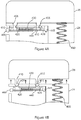
Figures 4A and 4B , an example releasable engagement mechanism is illustrated in both retained (Figure 4A ) and released (Figure 4B ) states.Figure 4A shows thecartridge 26 and thedevice body 21 of the delivery device ofFigure 2 . Thecartridge 26 is engaged with thedevice body 21 vialugs 410 on thecartridge 26 which project into thedevice body 21 throughapertures 405 to engage withclips 420 within thedevice body 21. Thelugs 410 comprise a recessed part 412 (shown inFigure 4B ) into which a projecting part or edge of theclips 420 can be received to provide engagement. Theclips 420 are movable between a retaining position (as shown inFigure 4A ) and a releasing position (as shown inFigure 4B ). Normally, theclips 420 are held in the retaining position shown inFigure 4A by aspring 430. However, in the event of a fault being detected, an electric current is passed through a wire element (muscle wire) 440, which is attached to a sliding structure on which the clips are provided, and to a fixedmounting point 445 within thedevice body 21. The electric current causes thewire element 440 to contract, which pulls the sliding structure, and thus theclips 420, towards the fixedmounting point 445 against the bias provided by thespring 430. This causes theclips 420 to move out of engagement with thelugs 410, and into the position shown inFigure 4B . Thelugs 410 are unable to follow the movement of theclips 420, since they are constrained within theapertures 405 against lateral movement. As a result, theclips 420 are no longer positioned to prevent the lugs from being withdrawn out of theapertures 405. Aspring 450 is visible inFigure 4A . This is the biasing member ofFigure 2 , and it can be seen that at one end it presses against thecartridge 26. While theclips 420 are engaged with thelugs 410, this biasing force is unable to separate thecartridge 26 from thedevice body 21, but once theclips 420 are no longer engaged with thelugs 410, the biasing force acts to separate thecartridge 26 from the device body, causing thelugs 410 to exit thedevice body 21 via theapertures 405, and thecartridge 26 to be forcibly ejected away from thedevice body 21. It is also possible for the sliding structure carrying theclips 420 to be moved manually by a user pressing arelease actuator 460. The manual force provided by the user pressing inwardly on therelease actuator 460 acts against the bias provided by thespring 430 in like manner to thewire element 440, causing the same disengagement of theclips 420 from thelugs 410 and separation of thecartridge 26 from thedevice body 21. In this way a user is able to remove an empty cartridge in order that a new cartridge can be fitted to thedevice body 21. It will be appreciated that, to engage acartridge 26 with thedevice body 21, thecartridge 26 can be positioned so that itslugs 410 line up with theapertures 405 in the device body, and thecartridge 26 is then pressed against thedevice body 21. It will be seen fromFigures 4A and 4B that the edges of theapertures 405 and the lugs are bevelled/chamfered to facilitate entry of thelugs 410 into the apertures, and also that the top portion of theclips 420 are bevelled/chamfered so that, when thelugs 410 are urged against the top portion of theclips 420 while theclips 420 are in the retaining position (which would block passage of the lugs 410), the sloped surfaces of theclips 420 and lugs 410 will cause the sliding structure to be deflected into the releasing position to allow thelugs 410 to pass theclips 410, whereupon theslips 420 will snap back into the retaining position to engage with the recessedpart 412 of thelugs 410. - Referring to
Figures 5A and 5B , these show the same elements asFigures 4A and 4B , but 3D view. Clearly visible inFigures 5A and 5B is thereservoir portion 470 of thecartridge 26, which is received within thedevice body 21. It can be seen that thespring 450 is received within thereservoir portion 470 of the cartridge 26 (as described above with reference toFigure 2 ). When theclips 420 release thelugs 410, the force exerted by thespring 450 within thereservoir 470 acts to eject thecartridge 26 from thedevice body 21. It can also be seen more clearly fromFigures 5A and 5B that theclips 420 and the sliding structure are formed as a single (preferably plastic) element which slides reciprocally within a channel (not shown). - Referring to
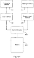
Figure 6 , the detection of a fault and actuation of the ejection of thecartridge 26 from thedevice body 21 is schematically illustrated. A biasingmember 610 acts against the base of an insulin reservoir of the cartridge 26 (as described in relation toFigure 2 ). The rate at which the biasingmember 610 moves is proportional and related to the rate of delivery of insulin from thecartridge 26 to the patient. The current position of the biasingelement 610 is determined by adisplacement sensor 620 which is mechanically coupled to the biasingelement 610. The determined position of the biasing element is notified to controlcircuitry 630, which is powered by abattery 640, and which calculates from the determined position with respect to time, a rate of delivery of insulin to the patient. If the calculated rate of delivery exceeds a predetermined fault threshold, then thecontrol circuitry 630 causes an electric current to be drawn from thebattery 640 and applied to awire element 650. The electric current causes thewire element 650 to contract, which moves a releasingelement 660 from a retaining position to a releasing position. When this happens, the biasing force applied by the biasingelement 610 acts against thecartridge 26 to release thecartridge 26 from thedevice body 21. InFigure 6 , solid lines denote electrical connection while dashed lines denote mechanical connection. - While embodiments of the present invention have been described with reference to an insulin delivery system, it will be appreciated that the present invention may be applied instead to the delivery of other drugs.
Claims (11)
- A therapeutic product delivery device (2) comprising:a device body (21);a cartridge (26) for holding a therapeutic product;an engagement structure (420) for releasably engaging the cartridge (26) with the device body (21);a fault detector (630) for detecting a fault in the delivery of the therapeutic product from the cartridge (26); anda release trigger, responsive to the detection of a fault to cause the engagement structure to release the cartridge (26) from the device body (21).
- A therapeutic product delivery device (2) according to claim 1, wherein the cartridge (26) comprises a reservoir (27) containing the therapeutic product and a pumping device (29) for pumping the therapeutic product from the reservoir (27) to the patient.
- A therapeutic product delivery device (2) according to claim 2, wherein
the device body (21) comprises a biasing element (450) which presses against the reservoir (27) of the cartridge (26) when the cartridge (26) is engaged with the device body (21); and
the force exerted by the biasing element (450) on the cartridge (26) causes the cartridge (26) to be ejected away from the device body (21) when the engagement structure (420) releases the cartridge (26) from the device body (21). - A therapeutic product delivery device (2) according to claim 3, wherein the biasing element comprises a spring (450).
- A therapeutic product delivery device (2) according to claim 1, wherein the engagement structure comprises one or more first engaging elements (420) on one or other of the device body (21) and the cartridge (26), the first engaging elements (420) being engagable with one or more corresponding second engaging elements (410) on the other of the device body (21) and the cartridge (26).
- A therapeutic product delivery device (2) according to claim 5, wherein the first engaging elements are clips (420), and the second engaging elements are lugs (410).
- A therapeutic product delivery device (2) according to claim 5, wherein the engagement structure comprises a releasing element which is moveable between a retaining position in which the first engaging elements (420) are able to engage the second engaging elements (410), and a releasing position in which the first engaging elements are not able to engage with the second engaging elements, and a wire element (440) which is deformable in response to an applied electric current to move the releasing element from the retaining position to the releasing position; and
the release trigger is responsive to the detection of the fault to apply an electric current to the wire element, thereby deforming the wire element (440). - A therapeutic product delivery device (2) according to claim 7, wherein the engagement structure comprises a spring (430) which biases the releasing element towards the retaining position, the wire element (440) acting against the bias in response to the applied electric current to move the releasing element into the releasing position.
- A therapeutic product delivery device (2) according to claim 7 or claim 8, comprising a release actuator (460), responsive to user manipulation to move the releasing element from the retaining position to the releasing position.
- A therapeutic product delivery device (2) according to claim 1, wherein the fault detector (630) detects a fault when the rate of delivery of the therapeutic product exceeds a predetermined threshold rate.
- A therapeutic product delivery device (2) according to claim 3, wherein the biasing element presses against a movable element of the reservoir (27), and the fault detector (630) comprises a displacement sensor for detecting a position of the movable element and detection circuitry for detecting a fault when the position of the movable element (23) changes at a rate above a predetermined threshold rate.
Applications Claiming Priority (2)
| Application Number | Priority Date | Filing Date | Title |
|---|---|---|---|
| GB1401587.9A GB2525149A (en) | 2014-01-30 | 2014-01-30 | Therapeutic product delivery device |
| PCT/GB2015/050251 WO2015114373A1 (en) | 2014-01-30 | 2015-01-30 | Therapeutic product delivery device |
Publications (2)
| Publication Number | Publication Date |
|---|---|
| EP3099355A1 EP3099355A1 (en) | 2016-12-07 |
| EP3099355B1 true EP3099355B1 (en) | 2018-03-14 |
Family
ID=50344097
Family Applications (1)
| Application Number | Title | Priority Date | Filing Date |
|---|---|---|---|
| EP15708021.9A Active EP3099355B1 (en) | 2014-01-30 | 2015-01-30 | Therapeutic product delivery device |
Country Status (12)
| Country | Link |
|---|---|
| US (2) | US10449290B2 (en) |
| EP (1) | EP3099355B1 (en) |
| JP (1) | JP6523307B2 (en) |
| KR (1) | KR101869769B1 (en) |
| CN (1) | CN106029126B (en) |
| CA (1) | CA2935692C (en) |
| DK (1) | DK3099355T3 (en) |
| GB (1) | GB2525149A (en) |
| HK (1) | HK1216400A1 (en) |
| MX (1) | MX2016009551A (en) |
| TW (1) | TW201531316A (en) |
| WO (1) | WO2015114373A1 (en) |
Families Citing this family (14)
| Publication number | Priority date | Publication date | Assignee | Title |
|---|---|---|---|---|
| PL1762259T3 (en) | 2005-09-12 | 2011-03-31 | Unomedical As | Inserter for an infusion set with a first and second spring units |
| MX2012011085A (en) | 2010-03-30 | 2012-10-10 | Unomedical As | Medical device. |
| US10194938B2 (en) | 2011-03-14 | 2019-02-05 | UnoMedical, AS | Inserter system with transport protection |
| CN103957962B (en) | 2011-10-05 | 2017-07-07 | 犹诺医药有限公司 | Insert for inserting multiple percutaneous parts simultaneously |
| EP2583715A1 (en) | 2011-10-19 | 2013-04-24 | Unomedical A/S | Infusion tube system and method for manufacture |
| US10441717B2 (en) | 2014-04-15 | 2019-10-15 | Insulet Corporation | Monitoring a physiological parameter associated with tissue of a host to confirm delivery of medication |
| CN108778370B (en) | 2016-01-19 | 2021-10-08 | 优诺医疗有限公司 | Cannula and infusion device |
| JP6710056B2 (en) * | 2016-02-04 | 2020-06-17 | テルモ株式会社 | Chemical dosing device |
| US11278665B2 (en) | 2016-11-22 | 2022-03-22 | Eitan Medical Ltd. | Method for delivering a therapeutic substance |
| TWI685359B (en) * | 2018-11-28 | 2020-02-21 | 永磐科技股份有限公司 | Intravenous drip monitoring system and method |
| US11241532B2 (en) | 2018-08-29 | 2022-02-08 | Insulet Corporation | Drug delivery system with sensor having optimized communication and infusion site |
| US11357909B2 (en) | 2018-10-05 | 2022-06-14 | Eitan Medical Ltd. | Triggering sequence |
| EP3659645A1 (en) * | 2018-11-30 | 2020-06-03 | Sensile Medical AG | Drug delivery device |
| WO2020236796A1 (en) | 2019-05-20 | 2020-11-26 | Unomedical A/S | Rotatable infusion device and methods thereof |
Family Cites Families (18)
| Publication number | Priority date | Publication date | Assignee | Title |
|---|---|---|---|---|
| SE372909B (en) | 1972-11-27 | 1975-01-20 | Wifag Maschf | |
| US7766873B2 (en) * | 1998-10-29 | 2010-08-03 | Medtronic Minimed, Inc. | Method and apparatus for detecting occlusions in an ambulatory infusion pump |
| US7193521B2 (en) * | 1998-10-29 | 2007-03-20 | Medtronic Minimed, Inc. | Method and apparatus for detecting errors, fluid pressure, and occlusions in an ambulatory infusion pump |
| US7905868B2 (en) * | 2006-08-23 | 2011-03-15 | Medtronic Minimed, Inc. | Infusion medium delivery device and method with drive device for driving plunger in reservoir |
| GB2443260C (en) | 2006-10-26 | 2017-11-29 | Cellnovo Ltd | Micro-valve |
| GB2456681B (en) | 2006-10-26 | 2009-11-11 | Starbridge Systems Ltd | Pump |
| GB0709580D0 (en) * | 2007-05-18 | 2007-06-27 | Abbi Lab Ltd | Infusion pump |
| US7828528B2 (en) * | 2007-09-06 | 2010-11-09 | Asante Solutions, Inc. | Occlusion sensing system for infusion pumps |
| CA2954728C (en) * | 2008-09-15 | 2019-03-26 | Deka Products Limited Partnership | Systems and methods for fluid delivery |
| GB2464114B (en) | 2008-10-02 | 2012-06-13 | Cellnovo Ltd | Linear capacitive displacement sensor |
| US8287487B2 (en) * | 2008-10-15 | 2012-10-16 | Asante Solutions, Inc. | Infusion pump system and methods |
| WO2010078207A1 (en) * | 2008-12-31 | 2010-07-08 | Deka Products Limited Partnership | Split ring resonator antenna adapted for use in wirelessly controlled medical device |
| WO2010146579A1 (en) | 2009-06-14 | 2010-12-23 | Medingo Ltd. | Devices and methods for malfunctions recognition in a therapeutic dispensing device |
| MX339532B (en) * | 2010-04-21 | 2016-05-30 | Abbvie Biotechnology Ltd | Wearable automatic injection device for controlled delivery of therapeutic agents. |
| US20110319861A1 (en) * | 2010-06-29 | 2011-12-29 | Robert Wilk | Medical device mechanical pump |
| CN103796696B (en) * | 2011-05-25 | 2016-02-03 | 赛诺菲-安万特德国有限公司 | There is the agent delivery device of dispensing interface and control the method for this device |
| US8454557B1 (en) * | 2012-07-19 | 2013-06-04 | Asante Solutions, Inc. | Infusion pump system and method |
| WO2015018787A1 (en) * | 2013-08-05 | 2015-02-12 | Sanofi-Aventis Deutschland Gmbh | Cover biasing means for an apparatus |
-
2014
- 2014-01-30 GB GB1401587.9A patent/GB2525149A/en not_active Withdrawn
-
2015
- 2015-01-30 DK DK15708021.9T patent/DK3099355T3/en active
- 2015-01-30 TW TW104103169A patent/TW201531316A/en unknown
- 2015-01-30 WO PCT/GB2015/050251 patent/WO2015114373A1/en active Application Filing
- 2015-01-30 MX MX2016009551A patent/MX2016009551A/en unknown
- 2015-01-30 CA CA2935692A patent/CA2935692C/en active Active
- 2015-01-30 CN CN201580005880.4A patent/CN106029126B/en not_active Expired - Fee Related
- 2015-01-30 EP EP15708021.9A patent/EP3099355B1/en active Active
- 2015-01-30 JP JP2016548379A patent/JP6523307B2/en not_active Expired - Fee Related
- 2015-01-30 US US15/114,840 patent/US10449290B2/en active Active
- 2015-01-30 KR KR1020167023326A patent/KR101869769B1/en active IP Right Grant
-
2016
- 2016-04-18 HK HK16104433.9A patent/HK1216400A1/en unknown
-
2019
- 2019-10-10 US US16/599,076 patent/US20200101218A1/en not_active Abandoned
Also Published As
| Publication number | Publication date |
|---|---|
| JP6523307B2 (en) | 2019-05-29 |
| DK3099355T3 (en) | 2018-06-25 |
| KR20160113253A (en) | 2016-09-28 |
| US20160339170A1 (en) | 2016-11-24 |
| TW201531316A (en) | 2015-08-16 |
| GB2525149A (en) | 2015-10-21 |
| GB201401587D0 (en) | 2014-03-19 |
| CA2935692A1 (en) | 2015-08-06 |
| EP3099355A1 (en) | 2016-12-07 |
| WO2015114373A1 (en) | 2015-08-06 |
| MX2016009551A (en) | 2016-10-21 |
| CA2935692C (en) | 2022-05-24 |
| KR101869769B1 (en) | 2018-06-21 |
| HK1216400A1 (en) | 2016-11-11 |
| US10449290B2 (en) | 2019-10-22 |
| US20200101218A1 (en) | 2020-04-02 |
| CN106029126B (en) | 2019-06-28 |
| JP2017504424A (en) | 2017-02-09 |
| CN106029126A (en) | 2016-10-12 |
Similar Documents
| Publication | Publication Date | Title |
|---|---|---|
| EP3099355B1 (en) | Therapeutic product delivery device | |
| US20210402092A1 (en) | Continuous glucose monitoring injection device | |
| US11386996B2 (en) | Therapeutic product delivery system and method of pairing | |
| EP3100188B1 (en) | Handset device | |
| EP3099347B1 (en) | Therapeutic product delivery device with occlusion detection via electric contacts | |
| EP3099936B1 (en) | Actuator and actuation method |
Legal Events
| Date | Code | Title | Description |
|---|---|---|---|
| PUAI | Public reference made under article 153(3) epc to a published international application that has entered the european phase |
Free format text: ORIGINAL CODE: 0009012 |
|
| STAA | Information on the status of an ep patent application or granted ep patent |
Free format text: STATUS: REQUEST FOR EXAMINATION WAS MADE |
|
| 17P | Request for examination filed |
Effective date: 20160715 |
|
| AK | Designated contracting states |
Kind code of ref document: A1 Designated state(s): AL AT BE BG CH CY CZ DE DK EE ES FI FR GB GR HR HU IE IS IT LI LT LU LV MC MK MT NL NO PL PT RO RS SE SI SK SM TR |
|
| AX | Request for extension of the european patent |
Extension state: BA ME |
|
| DAX | Request for extension of the european patent (deleted) | ||
| REG | Reference to a national code |
Ref country code: DE Ref legal event code: R079 Ref document number: 602015008817 Country of ref document: DE Free format text: PREVIOUS MAIN CLASS: A61M0005315000 Ipc: A61B0005145000 |
|
| GRAP | Despatch of communication of intention to grant a patent |
Free format text: ORIGINAL CODE: EPIDOSNIGR1 |
|
| STAA | Information on the status of an ep patent application or granted ep patent |
Free format text: STATUS: GRANT OF PATENT IS INTENDED |
|
| RIC1 | Information provided on ipc code assigned before grant |
Ipc: A61M 5/142 20060101ALI20170814BHEP Ipc: A61B 5/145 20060101AFI20170814BHEP Ipc: G06F 19/00 20110101ALI20170814BHEP Ipc: A61M 5/24 20060101ALI20170814BHEP Ipc: A61M 5/315 20060101ALI20170814BHEP |
|
| INTG | Intention to grant announced |
Effective date: 20170919 |
|
| RAP1 | Party data changed (applicant data changed or rights of an application transferred) |
Owner name: CELLNOVO LIMITED |
|
| GRAS | Grant fee paid |
Free format text: ORIGINAL CODE: EPIDOSNIGR3 |
|
| GRAA | (expected) grant |
Free format text: ORIGINAL CODE: 0009210 |
|
| STAA | Information on the status of an ep patent application or granted ep patent |
Free format text: STATUS: THE PATENT HAS BEEN GRANTED |
|
| AK | Designated contracting states |
Kind code of ref document: B1 Designated state(s): AL AT BE BG CH CY CZ DE DK EE ES FI FR GB GR HR HU IE IS IT LI LT LU LV MC MK MT NL NO PL PT RO RS SE SI SK SM TR |
|
| REG | Reference to a national code |
Ref country code: GB Ref legal event code: FG4D |
|
| REG | Reference to a national code |
Ref country code: CH Ref legal event code: EP Ref country code: AT Ref legal event code: REF Ref document number: 978064 Country of ref document: AT Kind code of ref document: T Effective date: 20180315 |
|
| REG | Reference to a national code |
Ref country code: IE Ref legal event code: FG4D |
|
| REG | Reference to a national code |
Ref country code: DE Ref legal event code: R096 Ref document number: 602015008817 Country of ref document: DE |
|
| REG | Reference to a national code |
Ref country code: CH Ref legal event code: NV Representative=s name: BOGENSBERGER PATENT- AND MARKENBUERO DR. BURKH, LI |
|
| REG | Reference to a national code |
Ref country code: RO Ref legal event code: EPE |
|
| REG | Reference to a national code |
Ref country code: DK Ref legal event code: T3 Effective date: 20180618 |
|
| REG | Reference to a national code |
Ref country code: LT Ref legal event code: MG4D |
|
| PG25 | Lapsed in a contracting state [announced via postgrant information from national office to epo] |
Ref country code: HR Free format text: LAPSE BECAUSE OF FAILURE TO SUBMIT A TRANSLATION OF THE DESCRIPTION OR TO PAY THE FEE WITHIN THE PRESCRIBED TIME-LIMIT Effective date: 20180314 Ref country code: NO Free format text: LAPSE BECAUSE OF FAILURE TO SUBMIT A TRANSLATION OF THE DESCRIPTION OR TO PAY THE FEE WITHIN THE PRESCRIBED TIME-LIMIT Effective date: 20180614 Ref country code: FI Free format text: LAPSE BECAUSE OF FAILURE TO SUBMIT A TRANSLATION OF THE DESCRIPTION OR TO PAY THE FEE WITHIN THE PRESCRIBED TIME-LIMIT Effective date: 20180314 Ref country code: LT Free format text: LAPSE BECAUSE OF FAILURE TO SUBMIT A TRANSLATION OF THE DESCRIPTION OR TO PAY THE FEE WITHIN THE PRESCRIBED TIME-LIMIT Effective date: 20180314 Ref country code: CY Free format text: LAPSE BECAUSE OF FAILURE TO SUBMIT A TRANSLATION OF THE DESCRIPTION OR TO PAY THE FEE WITHIN THE PRESCRIBED TIME-LIMIT Effective date: 20180314 |
|
| PG25 | Lapsed in a contracting state [announced via postgrant information from national office to epo] |
Ref country code: SE Free format text: LAPSE BECAUSE OF FAILURE TO SUBMIT A TRANSLATION OF THE DESCRIPTION OR TO PAY THE FEE WITHIN THE PRESCRIBED TIME-LIMIT Effective date: 20180314 Ref country code: LV Free format text: LAPSE BECAUSE OF FAILURE TO SUBMIT A TRANSLATION OF THE DESCRIPTION OR TO PAY THE FEE WITHIN THE PRESCRIBED TIME-LIMIT Effective date: 20180314 Ref country code: GR Free format text: LAPSE BECAUSE OF FAILURE TO SUBMIT A TRANSLATION OF THE DESCRIPTION OR TO PAY THE FEE WITHIN THE PRESCRIBED TIME-LIMIT Effective date: 20180615 Ref country code: RS Free format text: LAPSE BECAUSE OF FAILURE TO SUBMIT A TRANSLATION OF THE DESCRIPTION OR TO PAY THE FEE WITHIN THE PRESCRIBED TIME-LIMIT Effective date: 20180314 Ref country code: BG Free format text: LAPSE BECAUSE OF FAILURE TO SUBMIT A TRANSLATION OF THE DESCRIPTION OR TO PAY THE FEE WITHIN THE PRESCRIBED TIME-LIMIT Effective date: 20180614 |
|
| PG25 | Lapsed in a contracting state [announced via postgrant information from national office to epo] |
Ref country code: AL Free format text: LAPSE BECAUSE OF FAILURE TO SUBMIT A TRANSLATION OF THE DESCRIPTION OR TO PAY THE FEE WITHIN THE PRESCRIBED TIME-LIMIT Effective date: 20180314 Ref country code: EE Free format text: LAPSE BECAUSE OF FAILURE TO SUBMIT A TRANSLATION OF THE DESCRIPTION OR TO PAY THE FEE WITHIN THE PRESCRIBED TIME-LIMIT Effective date: 20180314 Ref country code: ES Free format text: LAPSE BECAUSE OF FAILURE TO SUBMIT A TRANSLATION OF THE DESCRIPTION OR TO PAY THE FEE WITHIN THE PRESCRIBED TIME-LIMIT Effective date: 20180314 Ref country code: PL Free format text: LAPSE BECAUSE OF FAILURE TO SUBMIT A TRANSLATION OF THE DESCRIPTION OR TO PAY THE FEE WITHIN THE PRESCRIBED TIME-LIMIT Effective date: 20180314 |
|
| PG25 | Lapsed in a contracting state [announced via postgrant information from national office to epo] |
Ref country code: SK Free format text: LAPSE BECAUSE OF FAILURE TO SUBMIT A TRANSLATION OF THE DESCRIPTION OR TO PAY THE FEE WITHIN THE PRESCRIBED TIME-LIMIT Effective date: 20180314 Ref country code: CZ Free format text: LAPSE BECAUSE OF FAILURE TO SUBMIT A TRANSLATION OF THE DESCRIPTION OR TO PAY THE FEE WITHIN THE PRESCRIBED TIME-LIMIT Effective date: 20180314 Ref country code: SM Free format text: LAPSE BECAUSE OF FAILURE TO SUBMIT A TRANSLATION OF THE DESCRIPTION OR TO PAY THE FEE WITHIN THE PRESCRIBED TIME-LIMIT Effective date: 20180314 |
|
| REG | Reference to a national code |
Ref country code: DE Ref legal event code: R097 Ref document number: 602015008817 Country of ref document: DE |
|
| PG25 | Lapsed in a contracting state [announced via postgrant information from national office to epo] |
Ref country code: PT Free format text: LAPSE BECAUSE OF FAILURE TO SUBMIT A TRANSLATION OF THE DESCRIPTION OR TO PAY THE FEE WITHIN THE PRESCRIBED TIME-LIMIT Effective date: 20180716 |
|
| PLBE | No opposition filed within time limit |
Free format text: ORIGINAL CODE: 0009261 |
|
| STAA | Information on the status of an ep patent application or granted ep patent |
Free format text: STATUS: NO OPPOSITION FILED WITHIN TIME LIMIT |
|
| 26N | No opposition filed |
Effective date: 20181217 |
|
| PG25 | Lapsed in a contracting state [announced via postgrant information from national office to epo] |
Ref country code: SI Free format text: LAPSE BECAUSE OF FAILURE TO SUBMIT A TRANSLATION OF THE DESCRIPTION OR TO PAY THE FEE WITHIN THE PRESCRIBED TIME-LIMIT Effective date: 20180314 |
|
| PGFP | Annual fee paid to national office [announced via postgrant information from national office to epo] |
Ref country code: LU Payment date: 20190125 Year of fee payment: 5 |
|
| PGFP | Annual fee paid to national office [announced via postgrant information from national office to epo] |
Ref country code: IE Payment date: 20190211 Year of fee payment: 11 Ref country code: IT Payment date: 20190125 Year of fee payment: 5 Ref country code: CH Payment date: 20190215 Year of fee payment: 5 |
|
| PGFP | Annual fee paid to national office [announced via postgrant information from national office to epo] |
Ref country code: DK Payment date: 20190128 Year of fee payment: 5 Ref country code: BE Payment date: 20190124 Year of fee payment: 5 |
|
| REG | Reference to a national code |
Ref country code: AT Ref legal event code: UEP Ref document number: 978064 Country of ref document: AT Kind code of ref document: T Effective date: 20180314 |
|
| PG25 | Lapsed in a contracting state [announced via postgrant information from national office to epo] |
Ref country code: MC Free format text: LAPSE BECAUSE OF FAILURE TO SUBMIT A TRANSLATION OF THE DESCRIPTION OR TO PAY THE FEE WITHIN THE PRESCRIBED TIME-LIMIT Effective date: 20180314 |
|
| REG | Reference to a national code |
Ref country code: DE Ref legal event code: R082 Ref document number: 602015008817 Country of ref document: DE Representative=s name: SAWODNY, MICHAEL, DIPL.-PHYS. DR.RER.NAT., DE Ref country code: DE Ref legal event code: R081 Ref document number: 602015008817 Country of ref document: DE Owner name: INSULET NETHERLANDS B.V., NL Free format text: FORMER OWNER: CELLNOVO LTD., BRIDGEND, GLAMORGAN, GB |
|
| REG | Reference to a national code |
Ref country code: GB Ref legal event code: 732E Free format text: REGISTERED BETWEEN 20200116 AND 20200122 |
|
| PG25 | Lapsed in a contracting state [announced via postgrant information from national office to epo] |
Ref country code: TR Free format text: LAPSE BECAUSE OF FAILURE TO SUBMIT A TRANSLATION OF THE DESCRIPTION OR TO PAY THE FEE WITHIN THE PRESCRIBED TIME-LIMIT Effective date: 20180314 |
|
| PG25 | Lapsed in a contracting state [announced via postgrant information from national office to epo] |
Ref country code: MT Free format text: LAPSE BECAUSE OF NON-PAYMENT OF DUE FEES Effective date: 20190130 |
|
| REG | Reference to a national code |
Ref country code: DK Ref legal event code: EBP Effective date: 20200131 Ref country code: CH Ref legal event code: PL |
|
| REG | Reference to a national code |
Ref country code: NL Ref legal event code: FP Ref country code: NL Ref legal event code: MM Effective date: 20200201 |
|
| REG | Reference to a national code |
Ref country code: BE Ref legal event code: MM Effective date: 20200131 |
|
| PG25 | Lapsed in a contracting state [announced via postgrant information from national office to epo] |
Ref country code: RO Free format text: LAPSE BECAUSE OF NON-PAYMENT OF DUE FEES Effective date: 20200130 Ref country code: LU Free format text: LAPSE BECAUSE OF NON-PAYMENT OF DUE FEES Effective date: 20200130 Ref country code: NL Free format text: LAPSE BECAUSE OF NON-PAYMENT OF DUE FEES Effective date: 20200201 |
|
| PG25 | Lapsed in a contracting state [announced via postgrant information from national office to epo] |
Ref country code: BE Free format text: LAPSE BECAUSE OF NON-PAYMENT OF DUE FEES Effective date: 20200131 Ref country code: CH Free format text: LAPSE BECAUSE OF NON-PAYMENT OF DUE FEES Effective date: 20200131 Ref country code: LI Free format text: LAPSE BECAUSE OF NON-PAYMENT OF DUE FEES Effective date: 20200131 |
|
| PG25 | Lapsed in a contracting state [announced via postgrant information from national office to epo] |
Ref country code: DK Free format text: LAPSE BECAUSE OF NON-PAYMENT OF DUE FEES Effective date: 20200131 Ref country code: IT Free format text: LAPSE BECAUSE OF NON-PAYMENT OF DUE FEES Effective date: 20200130 |
|
| REG | Reference to a national code |
Ref country code: AT Ref legal event code: MM01 Ref document number: 978064 Country of ref document: AT Kind code of ref document: T Effective date: 20200130 |
|
| PG25 | Lapsed in a contracting state [announced via postgrant information from national office to epo] |
Ref country code: AT Free format text: LAPSE BECAUSE OF NON-PAYMENT OF DUE FEES Effective date: 20200130 |
|
| PG25 | Lapsed in a contracting state [announced via postgrant information from national office to epo] |
Ref country code: IS Free format text: LAPSE BECAUSE OF FAILURE TO SUBMIT A TRANSLATION OF THE DESCRIPTION OR TO PAY THE FEE WITHIN THE PRESCRIBED TIME-LIMIT Effective date: 20180714 |
|
| PG25 | Lapsed in a contracting state [announced via postgrant information from national office to epo] |
Ref country code: HU Free format text: LAPSE BECAUSE OF FAILURE TO SUBMIT A TRANSLATION OF THE DESCRIPTION OR TO PAY THE FEE WITHIN THE PRESCRIBED TIME-LIMIT; INVALID AB INITIO Effective date: 20150130 |
|
| PG25 | Lapsed in a contracting state [announced via postgrant information from national office to epo] |
Ref country code: MK Free format text: LAPSE BECAUSE OF FAILURE TO SUBMIT A TRANSLATION OF THE DESCRIPTION OR TO PAY THE FEE WITHIN THE PRESCRIBED TIME-LIMIT Effective date: 20180314 |
|
| PGFP | Annual fee paid to national office [announced via postgrant information from national office to epo] |
Ref country code: FR Payment date: 20230124 Year of fee payment: 9 |
|
| PGFP | Annual fee paid to national office [announced via postgrant information from national office to epo] |
Ref country code: GB Payment date: 20230119 Year of fee payment: 9 Ref country code: DE Payment date: 20220620 Year of fee payment: 9 |
|
| PG25 | Lapsed in a contracting state [announced via postgrant information from national office to epo] |
Ref country code: IE Free format text: LAPSE BECAUSE OF NON-PAYMENT OF DUE FEES Effective date: 20230130 |