EP3099243B1 - An ultrasound imaging system and an ultrasound imaging method - Google Patents
An ultrasound imaging system and an ultrasound imaging method Download PDFInfo
- Publication number
- EP3099243B1 EP3099243B1 EP15701728.6A EP15701728A EP3099243B1 EP 3099243 B1 EP3099243 B1 EP 3099243B1 EP 15701728 A EP15701728 A EP 15701728A EP 3099243 B1 EP3099243 B1 EP 3099243B1
- Authority
- EP
- European Patent Office
- Prior art keywords
- ultrasound
- setting parameters
- transducer elements
- probe
- imaging plane
- Prior art date
- Legal status (The legal status is an assumption and is not a legal conclusion. Google has not performed a legal analysis and makes no representation as to the accuracy of the status listed.)
- Not-in-force
Links
Images


Classifications
-
- A—HUMAN NECESSITIES
- A61—MEDICAL OR VETERINARY SCIENCE; HYGIENE
- A61B—DIAGNOSIS; SURGERY; IDENTIFICATION
- A61B8/00—Diagnosis using ultrasonic, sonic or infrasonic waves
- A61B8/52—Devices using data or image processing specially adapted for diagnosis using ultrasonic, sonic or infrasonic waves
- A61B8/5215—Devices using data or image processing specially adapted for diagnosis using ultrasonic, sonic or infrasonic waves involving processing of medical diagnostic data
- A61B8/523—Devices using data or image processing specially adapted for diagnosis using ultrasonic, sonic or infrasonic waves involving processing of medical diagnostic data for generating planar views from image data in a user selectable plane not corresponding to the acquisition plane
-
- A—HUMAN NECESSITIES
- A61—MEDICAL OR VETERINARY SCIENCE; HYGIENE
- A61B—DIAGNOSIS; SURGERY; IDENTIFICATION
- A61B8/00—Diagnosis using ultrasonic, sonic or infrasonic waves
- A61B8/13—Tomography
- A61B8/14—Echotomography
-
- A—HUMAN NECESSITIES
- A61—MEDICAL OR VETERINARY SCIENCE; HYGIENE
- A61B—DIAGNOSIS; SURGERY; IDENTIFICATION
- A61B8/00—Diagnosis using ultrasonic, sonic or infrasonic waves
- A61B8/13—Tomography
- A61B8/14—Echotomography
- A61B8/145—Echotomography characterised by scanning multiple planes
-
- A—HUMAN NECESSITIES
- A61—MEDICAL OR VETERINARY SCIENCE; HYGIENE
- A61B—DIAGNOSIS; SURGERY; IDENTIFICATION
- A61B8/00—Diagnosis using ultrasonic, sonic or infrasonic waves
- A61B8/44—Constructional features of the ultrasonic, sonic or infrasonic diagnostic device
- A61B8/4483—Constructional features of the ultrasonic, sonic or infrasonic diagnostic device characterised by features of the ultrasound transducer
- A61B8/4488—Constructional features of the ultrasonic, sonic or infrasonic diagnostic device characterised by features of the ultrasound transducer the transducer being a phased array
-
- A—HUMAN NECESSITIES
- A61—MEDICAL OR VETERINARY SCIENCE; HYGIENE
- A61B—DIAGNOSIS; SURGERY; IDENTIFICATION
- A61B8/00—Diagnosis using ultrasonic, sonic or infrasonic waves
- A61B8/44—Constructional features of the ultrasonic, sonic or infrasonic diagnostic device
- A61B8/4483—Constructional features of the ultrasonic, sonic or infrasonic diagnostic device characterised by features of the ultrasound transducer
- A61B8/4494—Constructional features of the ultrasonic, sonic or infrasonic diagnostic device characterised by features of the ultrasound transducer characterised by the arrangement of the transducer elements
-
- A—HUMAN NECESSITIES
- A61—MEDICAL OR VETERINARY SCIENCE; HYGIENE
- A61B—DIAGNOSIS; SURGERY; IDENTIFICATION
- A61B8/00—Diagnosis using ultrasonic, sonic or infrasonic waves
- A61B8/46—Ultrasonic, sonic or infrasonic diagnostic devices with special arrangements for interfacing with the operator or the patient
- A61B8/461—Displaying means of special interest
- A61B8/465—Displaying means of special interest adapted to display user selection data, e.g. icons or menus
-
- A—HUMAN NECESSITIES
- A61—MEDICAL OR VETERINARY SCIENCE; HYGIENE
- A61B—DIAGNOSIS; SURGERY; IDENTIFICATION
- A61B8/00—Diagnosis using ultrasonic, sonic or infrasonic waves
- A61B8/46—Ultrasonic, sonic or infrasonic diagnostic devices with special arrangements for interfacing with the operator or the patient
- A61B8/461—Displaying means of special interest
- A61B8/466—Displaying means of special interest adapted to display 3D data
-
- A—HUMAN NECESSITIES
- A61—MEDICAL OR VETERINARY SCIENCE; HYGIENE
- A61B—DIAGNOSIS; SURGERY; IDENTIFICATION
- A61B8/00—Diagnosis using ultrasonic, sonic or infrasonic waves
- A61B8/46—Ultrasonic, sonic or infrasonic diagnostic devices with special arrangements for interfacing with the operator or the patient
- A61B8/467—Ultrasonic, sonic or infrasonic diagnostic devices with special arrangements for interfacing with the operator or the patient characterised by special input means
- A61B8/469—Ultrasonic, sonic or infrasonic diagnostic devices with special arrangements for interfacing with the operator or the patient characterised by special input means for selection of a region of interest
-
- A—HUMAN NECESSITIES
- A61—MEDICAL OR VETERINARY SCIENCE; HYGIENE
- A61B—DIAGNOSIS; SURGERY; IDENTIFICATION
- A61B8/00—Diagnosis using ultrasonic, sonic or infrasonic waves
- A61B8/48—Diagnostic techniques
- A61B8/483—Diagnostic techniques involving the acquisition of a 3D volume of data
-
- A—HUMAN NECESSITIES
- A61—MEDICAL OR VETERINARY SCIENCE; HYGIENE
- A61B—DIAGNOSIS; SURGERY; IDENTIFICATION
- A61B8/00—Diagnosis using ultrasonic, sonic or infrasonic waves
- A61B8/54—Control of the diagnostic device
Definitions
- the present invention relates to ultrasound imaging, more particularly to an ultrasound imaging system and an ultrasound imaging method for improving the imaging quality of the desired imaging plane in the volume of interest of a subject.
- a conventional one-dimensional (1D) ultrasound probe comprises a line of transducer elements from which ultrasonic signals may be emitted. Furthermore, an image plane underneath the transducer elements may be observed by detecting echoes of reflected ultrasonic signals coming from inhomogeneities of the observed region. By correctly positioning and moving the ultrasound transducer, a volume of interest of the subject comprising for example a lesion may be observed.
- the research work done for this goal is mainly based on 3D (acquired by using a matrix transducer comprising a two-dimensional array of transducer elements) or higher-dimensional data and once the high-dimensional data is obtained, the desired imaging plane with the object that doctors want to see may be determined and the corresponding 2D image of the desired imaging plane is displayed.
- such a transducer may comprise an array of ultrasound transducer elements arranged in columns and rows.
- the transducer array face may still be rectangular as in the case of a one-dimensional ultrasound transducer, but the array of transducer elements is arranged in a two-dimensional matrix.
- This additional complexity may allow ultrasound beams to be steered and focused through a three-dimensional space rather than in only a plane.
- the two-dimensional matrix ultrasound transducer may acquire the three-dimensional volume data of the volume of interest from ultrasound echo data of a plurality of scanning planes in the volume of interest.
- the plurality of scanning planes may be determined by the setting parameters for the transducer elements, for example, which lines or rows are to be enabled, and the beam-forming parameters for the enabled elements.
- any desired image plane can be reconstructed via computer processing algorithms, for example, by interpolation of the ultrasound echo data of the plurality of scanning planes.
- the quality of the reconstructed and displayed 2D image of the desired imaging plane may be unsatisfactory.
- the image of the determined desired imaging plane may not be constructed in the transmit direction of the ultrasound signal. Since the ultrasound signal will have a signal focusing process and the corresponding interpolation process, if the image of the desired imaging plane is not generated in the transmit direction (i.e., not generated by the ultrasound echo data of the desired imaging plane itself) but reconstructed by interpolation of the ultrasound echo data of the plurality of scanning planes in the volume of interest, the quality of the constructed 2D image may be highly affected and sometimes clinical diagnosis cannot be performed for some applications where a high data quality is required.
- Patent application publication US 2012/157845 A1 describes an ultrasound imaging system and method that include: acquiring first ultrasound data, the first ultrasound data comprising data of a first plane through a structure of interest; tracking the motion of a landmark based on the first ultrasound data; and acquiring second ultrasound data, the second ultrasound data including data of a second plane through the structure of interest, the second plane being distinct from the first plane, where the position of the second plane is adjusted to track the motion of the landmark.
- the ultrasound imaging system and method also includes generating an image based on the second ultrasound data.
- Document US 2010/260398 A1 relates to a systems and a method which provide volume imaging by implementing survey and target imaging modes.
- the survey imaging mode is implemented to provide a volume image of a relatively large survey area.
- a target of interest is preferably identified within the survey area for use in the target imaging mode.
- the target imaging mode is implemented to provide a volume image of a relatively small target area corresponding to the identified target of interest.
- the target imaging mode preferably adapts the beamforming, volume field of view and/or other signal and image processing algorithms to the target area. In operation, the target imaging mode provides a volume image of a target area with improved volume rate and image quality.
- an ultrasound imaging system comprising:
- the setting parameters of the transducer elements can be adjusted so that the ultrasound signal transmitted from the transducer elements is able to derive ultrasound echo data of the desired imaging plane without moving the probe.
- the adjustment of the position/orientation of the ultrasound probe is possible by means of user interaction, namely outputting the instruction for guiding the user to move the probe so as to enable direct scanning of the desired imaging plane.
- the image of the desired imaging plane is not reconstructed by interpolation of the ultrasound echo data of the plurality of scanning planes (which are determined by the setting parameters of the transducer elements), but the image is reconstructed from the ultrasound echo data of the desired imaging plane itself.
- the desired imaging plane is directly scanned.
- the image quality of the desired imaging plane is improved and may help doctors conduct a more accurate diagnosis.
- the setting parameters of the transducer elements comprise which transducer elements are to be enabled and the beam-forming parameters for the enabled transducer elements.
- the beam-forming parameters of the transducer elements may comprise, for example, the phase of the ultrasound signals transmitted by each of the enabled transducer elements and/or the beam-forming vectors adopted in the beam-forming element on the receiving side to synthesize the echo data of the ultrasound signals transmitted by the enabled transducer elements.
- the elements of the transducer that should be enabled are determined first, and then the beam-forming parameters for the enabled elements are determined.
- the corresponding elements of the transducer that should be enabled By first determining the corresponding elements of the transducer that should be enabled, it is possible to preliminarily constrain the set of planes that can be imaged in the volume of interest. Meanwhile, by not enabling all the elements the processing cost is reduced. Furthermore, the corresponding detailed direction of the transmitting signal is then determined by adjusting beam-forming parameters for the enabled elements. In this way, the transmitting signal from the enabled elements uniquely corresponds to the desired imaging plane.
- the processing unit is configured to automatically determine the desired imaging plane for the volume of interest in accordance with the three-dimensional volume data, a clinical objective and a predetermined model.
- the plane detection methods could be different Hough transforms, segmentation-based methods or graphical models of different objects, etc. It should be noted that automatic determination of the desired imaging plane is realized in real-time here, which could provide more information for the whole of the process and for the following scanning plan as compared with conventional approaches.
- the ultrasound imaging system may further comprise a user interface for receiving the user's input.
- the display may be further configured to display a plurality of images reconstructed from the three-dimensional volume data
- the processing unit may be further configured to determine the desired imaging plane for the volume of interest in accordance with the user's manual selection based on the plurality of images reconstructed from the three-dimensional volume data.
- an ultrasound imaging method comprising:
- the ultrasound imaging method according to the present invention may improve the image quality of the desired imaging plane and may help doctors conduct a more accurate diagnosis since the image of the desired imaging plane is not reconstructed by processing the imaging data of one or more imaging planes different from the desired imaging plane but by directly processing the imaging data of the desired imaging plane.
- Fig. 1 is a block diagram of an ultrasound imaging system 10 according to the present invention.
- FIG. 2 is a block diagram of the ultrasound imaging method 20 according to the present invention.
- the ultrasound imaging system 10 of the present invention comprises an ultrasound probe 11.
- a two-dimensional array of transducer elements 110 is utilized in the probe 11, for transmitting ultrasound signals and acquiring three-dimensional volume data of a volume of interest of a subject (step 21 in Fig. 2 ).
- the subject may be a patient and the volume of interest of the subject may be an organ of the patient.
- the position at which the probe 11 is positioned on the subject when the three-dimensional volume data is acquired is referred to as the first position and the angle at which the probe is tilted relative to the volume of interest is referred to as the first angle.
- a two-dimensional matrix ultrasound transducer may comprise an array of ultrasound transducer elements 110 arranged in columns and rows.
- the transducer array face may still be rectangular as in the case of a one-dimensional ultrasound transducer, but the array of transducer elements is arranged in a two-dimensional matrix.
- a first set of setting parameters is predetermined for the transducer elements 110 of the probe 11. In other words, the first set of setting parameters determines which transducer elements are to be enabled as well as the beam-forming parameters for the enabled transducer elements.
- the first set of setting parameters determines that a plurality of scanning planes of the two-dimensional matrix ultrasound transducer are arranged in columns or in rows, or even in diagonal directions. Accordingly, the acquired three-dimensional volume data of the volume of interest comprises ultrasound echo data of the plurality of scanning planes defined by the first set of setting parameters.
- the ultrasound imaging system 10 further comprises a processing unit 12 for determining a desired imaging plane 1 for the volume of interest in accordance with the three-dimensional volume data (step 21 in Fig. 2 ).
- the processing unit 12 may be configured to automatically determine the desired imaging plane 1 for the volume of interest in accordance with the acquired three-dimensional volume data, a clinical objective and a predetermined model.
- the plane detection methods could be different Hough transforms, segmentation-based methods or graphical models of different objects, etc. It should be noted that the automatic determination of the desired imaging plane is realized in real-time here, which could provide more information for the whole of the process and for a following scanning plan as compared with conventional approaches.
- the ultrasound imaging system 10 may further comprise a user interface for receiving the user's input.
- the display may be further configured to display a plurality of images reconstructed from the three-dimensional volume data
- the processing unit 12 may be further configured to determine the desired imaging plane 1 for the volume of interest in accordance with the user's manual selection based on the plurality of images reconstructed from the three-dimensional volume data.
- the ultrasound system can be further configured to allow doctors to find the plane by themselves.
- doctors can be provided with means to manually move the plane, and the plane position should be displayed in the current total 3D data. Since this should be performed in real-time during the scanning process, the interpretation of the displayed2 D image should not be more complicated than the conventional scanning operation. Meanwhile the spatial information is provided, which makes it more convenient for doctors to interpret the image.
- the desired imaging plane 1 for the volume of interest is determined by considering the particular anatomical structure of the volume of interest and the particular target in the volume of interest, for example a potential lesion, and therefore is usually not one of the scanning planes. However, only the image of the scanning plane is generated from the transmitting signal in the transmit direction.
- the desired imaging plane 1 is not one of the scanning planes, the image thereof is not reconstructed in the transmit direction of the ultrasound signal, i.e., not generated by the ultrasound echo data of the desired imaging plane itself, but reconstructed by interpolation of the ultrasound echo data of the plurality of scanning planes in the volume of interest, but the quality of the reconstructed 2D image may be highly adversely affected and sometimes clinical diagnosis cannot be performed for applications where high data quality is required.
- the present invention exploits the capability of a 2D matrix ultrasound transducer, in which the enabled transducer elements and the beam-forming parameters for the enabled elements may be adjusted so that the ultrasound signal transmitted from the enabled transducer elements is able to derive ultrasound echo data of the desired imaging plane without moving the probe or after moving the probe to another position and tilted at another angle relative to the volume of interest.
- the processing unit 12 of the present invention is further used to determine a result whether there is a second set of setting parameters such that the ultrasound signal transmitted from the transducer elements having the second set of setting parameters is able to acquire ultrasound echo data of the desired imaging plane without moving the probe 11 (step 23 in Fig. 2 ).
- the processing unit 12 is further configured to derive the second set of setting parameters (step 24 in Fig. 2 ).
- a transducer controller 13 comprised in the ultrasound imaging system 10 then adjusts the transducer elements 110 in accordance with the derived second set of setting parameters (step 25 in Fig. 2 ).
- the processing unit 12 is further configured to derive a second position and a second angle for the probe 11 and derive a third set of setting parameters for the transducer elements 110 such that when the probe 11 is moved to the second position on the subject and tilted at the second angle relative to the volume of interest, the ultrasound signal transmitted from the transducer elements having the third set of setting parameters is able to derive ultrasound echo data of the desired imaging plane (step 26 in Fig. 2 ).
- the transducer controller 13 then adjusts the transducer elements 110 in accordance with the derived third set of setting parameters (step 27 in Fig. 2 ).
- the processing unit 12 performs steps 23, 24 and 26 based on the spatial positional relationship between the first position and the first angle of the probe and the desired imaging plane 1 and based on the layout of the transducer elements 110.
- the ultrasound imaging system 10 further comprises a display 14. If the result is NO, i.e., if the probe 11 has to be moved, the display 14 is used to output an instruction to guide a user of the ultrasound imaging system 10 to move the probe 11 so as to be positioned at the second position and tilted at the second angle.
- the schematic view of how to guide the user to move the probe 11 is shown in Fig. 4a and Fig. 4b , and will be explained hereinafter.
- the display 14 is further configured to display an image of the desired imaging plane 1, which is reconstructed from the ultrasound echo data of the desired imaging plane 1.
- the image of the desired imaging plane 1 is not reconstructed by interpolation of the ultrasound echo data of the plurality of scanning planes (which correspond to the ultrasound signals transmitted from the initial enabled elements and initial beam-forming parameters), but reconstructed from the ultrasound echo data of the desired imaging plane itself.
- the image quality of the desired imaging plane 1 is improved and may help doctors conduct a more accurate diagnosis.
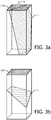
- step 23 i.e., the determination of whether there is a second set of setting parameters such that the ultrasound signal transmitted from the transducer elements having the second set of setting parameters is able to acquire ultrasound echo data of the desired imaging plane without moving the probe 11 is further elaborated hereinafter in conjunction with Figs. 3a and 3b , which illustrate, respectively, a condition where the desired imaging plane 1 is intersected with the two-dimensional array of transducer elements 110, and a condition where the desired imaging plane 1 is not intersected with the two-dimensional array of transducer elements 110.
- the desired imaging plane 1 is intersected with the two-dimensional array of transducer elements 110, it is determined that the result is YES, i.e., there is a second set of setting parameters such that the ultrasound signal transmitted from the transducer elements having the second set of setting parameters is able to acquire ultrasound echo data of the desired imaging plane without moving the probe 11.
- the transducer elements on the intersection line 1a would be enabled and the transducer elements adjacent to the intersection line 1a would usually be enabled. This may preliminarily constrain the set of planes that can be imaged in the volume of interest.
- the corresponding detailed direction of the transmitting signal is determined by adjusting beam-forming parameters for the enabled elements.
- the transmitting signal from the enabled elements uniquely corresponds to the desired imaging plane 1.
- the desired imaging plane 1 is not intersected with the two-dimensional array of transducer elements 110, it is determined that the result is NO, i.e., there is not a second set of setting parameters such that the ultrasound signal transmitted from the transducer elements having the second set of setting parameters is able to acquire ultrasound echo data of the desired imaging plane without moving the probe 11.
- the desired imaging plane 1, which is not intersected with the two-dimensional array of transducer elements 110 cannot be imaged with a real transmitting signal of the elements without moving the probe to another position different from the first position.
- the processing unit 12 is further configured to derive a second position and a second angle for the probe 11 and derive a third set of setting parameters for the transducer elements 110 such that when the probe 11 is moved to the second position on the subject and tilted at the second angle relative to the volume of interest, the ultrasound signal transmitted from the transducer elements having the third set of setting parameters is able to derive ultrasound echo data of the desired imaging plane (step 26 in Fig. 2 ).
- the second position and the second angle are both different from the first position and the first angle.
- the second angle may be the same as the first angle.
- Fig. 4a and Fig. 4b illustrate, in the case of Fig. 3b , how the display 14 of the ultrasound imaging system outputs an instruction to guide a user of the ultrasound imaging system to move the probe according to an embodiment of the present invention.
- the desired imaging plane 1 is not intersected with the two-dimensional array of transducer elements 110.
- a middle reference plane 2 which is underneath the centerline of the array of transducer elements 110, could be determined.
- the second position, the second angle and the third set of setting parameters such that when the probe 11 is moved to the second position on the subject and tilted at the second angle relative to the volume of interest, the ultrasound signal transmitted from the transducer elements 110 having the third set of setting parameters is able to derive ultrasound echo data of the desired imaging plane 1.
- the processing unit 12 is able to calculate the second position that the probe 11 should be moved to. Further, according to the spatial positional relationship between the centerline of the array of transducer elements 110 and the intersection line 1b of the middle reference plane 2 with the desired imaging plane 1, the processing unit 12 is able to calculate the second angle at which the probe 11 should be tilted relative to the volume of interest.
- the processing unit 12 may derive that, at the second position and the second angle, the transducer elements on the centerline of the array (and some elements adjacent to the centerline) should be enabled and the beam-forming parameters for the enabled transducer elements could be determined accordingly, so that the desired imaging plane 1 could be directly obtained by the transmitting signal from the enabled elements.
- middle reference plane 2 is only used as an embodiment; other reference planes may also be used and the second position, the second angle and the third set of setting parameters could be similarly derived according to the selection of the reference plane.
- the display 14 of the ultrasound imaging system 10 then outputs an instruction to guide a user of the ultrasound imaging system 10 to move the probe 11, for example the moving direction indicated by I 1 in Fig. 4b to guide the user to move the probe 11 to the second position and the rotation direction indicated by I 2 in Fig. 4b to guide the user to achieve the second angle of the probe 11.
- the instruction can be output in a format of text, graphics, or a combination thereof.
- the display 14 is capable of outputting audio, and the instruction can be output in an audio format.
Landscapes
- Health & Medical Sciences (AREA)
- Life Sciences & Earth Sciences (AREA)
- Engineering & Computer Science (AREA)
- Medical Informatics (AREA)
- Surgery (AREA)
- Pathology (AREA)
- Radiology & Medical Imaging (AREA)
- Biophysics (AREA)
- Biomedical Technology (AREA)
- Heart & Thoracic Surgery (AREA)
- Physics & Mathematics (AREA)
- Molecular Biology (AREA)
- Nuclear Medicine, Radiotherapy & Molecular Imaging (AREA)
- Animal Behavior & Ethology (AREA)
- General Health & Medical Sciences (AREA)
- Public Health (AREA)
- Veterinary Medicine (AREA)
- Gynecology & Obstetrics (AREA)
- Computer Graphics (AREA)
- General Engineering & Computer Science (AREA)
- Human Computer Interaction (AREA)
- Computer Vision & Pattern Recognition (AREA)
- Ultra Sonic Daignosis Equipment (AREA)
Description
- The present invention relates to ultrasound imaging, more particularly to an ultrasound imaging system and an ultrasound imaging method for improving the imaging quality of the desired imaging plane in the volume of interest of a subject.
- A conventional one-dimensional (1D) ultrasound probe comprises a line of transducer elements from which ultrasonic signals may be emitted. Furthermore, an image plane underneath the transducer elements may be observed by detecting echoes of reflected ultrasonic signals coming from inhomogeneities of the observed region. By correctly positioning and moving the ultrasound transducer, a volume of interest of the subject comprising for example a lesion may be observed.
- In ultrasound imaging of a volume of interest, a clinical challenge for doctors - especially junior doctors - is how to find an imaging plane for the volume of interest which is suitable or desirable for a certain clinical purpose. Supporting doctors to find the desired imaging plane is very valuable and highly required for clinical doctors. From the point of view of computerized techniques, the 2D image data acquired by the one-dimensional ultrasound probe may not provide sufficient information to do this, since the human body is a 3D object. Currently, the research work done for this goal is mainly based on 3D (acquired by using a matrix transducer comprising a two-dimensional array of transducer elements) or higher-dimensional data and once the high-dimensional data is obtained, the desired imaging plane with the object that doctors want to see may be determined and the corresponding 2D image of the desired imaging plane is displayed.
- As regards the two-dimensional matrix ultrasound transducer, such a transducer may comprise an array of ultrasound transducer elements arranged in columns and rows. The transducer array face may still be rectangular as in the case of a one-dimensional ultrasound transducer, but the array of transducer elements is arranged in a two-dimensional matrix. This additional complexity may allow ultrasound beams to be steered and focused through a three-dimensional space rather than in only a plane. As is known to those skilled in the art, the two-dimensional matrix ultrasound transducer may acquire the three-dimensional volume data of the volume of interest from ultrasound echo data of a plurality of scanning planes in the volume of interest. The plurality of scanning planes may be determined by the setting parameters for the transducer elements, for example, which lines or rows are to be enabled, and the beam-forming parameters for the enabled elements.
- Once the three-dimensional volume data of the volume of interest is acquired, any desired image plane can be reconstructed via computer processing algorithms, for example, by interpolation of the ultrasound echo data of the plurality of scanning planes.
- Nevertheless, although it may be easier for doctors to find the desired imaging plane for the volume of interest with a two-dimensional matrix ultrasound transducer, the quality of the reconstructed and displayed 2D image of the desired imaging plane may be unsatisfactory.
- Specifically, current automated means to reconstruct the 2D image of the desired imaging plane have some disadvantages, for example fixed enablement of the transmit elements of the matrix transducer regardless of the desirable imaging plane, etc. In other words, the image of the determined desired imaging plane may not be constructed in the transmit direction of the ultrasound signal. Since the ultrasound signal will have a signal focusing process and the corresponding interpolation process, if the image of the desired imaging plane is not generated in the transmit direction (i.e., not generated by the ultrasound echo data of the desired imaging plane itself) but reconstructed by interpolation of the ultrasound echo data of the plurality of scanning planes in the volume of interest, the quality of the constructed 2D image may be highly affected and sometimes clinical diagnosis cannot be performed for some applications where a high data quality is required.
- Patent application publication
US 2012/157845 A1 describes an ultrasound imaging system and method that include: acquiring first ultrasound data, the first ultrasound data comprising data of a first plane through a structure of interest; tracking the motion of a landmark based on the first ultrasound data; and acquiring second ultrasound data, the second ultrasound data including data of a second plane through the structure of interest, the second plane being distinct from the first plane, where the position of the second plane is adjusted to track the motion of the landmark. The ultrasound imaging system and method also includes generating an image based on the second ultrasound data. - Document
US 2010/260398 A1 relates to a systems and a method which provide volume imaging by implementing survey and target imaging modes. The survey imaging mode is implemented to provide a volume image of a relatively large survey area. A target of interest is preferably identified within the survey area for use in the target imaging mode. The target imaging mode is implemented to provide a volume image of a relatively small target area corresponding to the identified target of interest. The target imaging mode preferably adapts the beamforming, volume field of view and/or other signal and image processing algorithms to the target area. In operation, the target imaging mode provides a volume image of a target area with improved volume rate and image quality. - Therefore, there is a need for a novel ultrasound imaging system and method, which is capable of improving the imaging quality of the desired imaging plane.
- In accordance with an aspect of the present invention, there is proposed an ultrasound imaging system, comprising:
- an ultrasound probe with a two-dimensional array of transducer elements, for transmitting ultrasound signals and acquiring three-dimensional volume data of a volume of interest of a subject when the probe is positioned at a first position on the subject and tilted at a first angle relative to the volume of interest and the transducer elements of the probe have a first set of setting parameters, wherein the three-dimensional volume data of the volume of interest comprises ultrasound echo data of a plurality of scanning planes defined by the first set of setting parameters;
- a processing unit for determining a desired imaging plane for the volume of interest in accordance with the three-dimensional volume data and for determining a result whether there is a second set of setting parameters such that the ultrasound signal transmitted from the transducer elements having the second set of setting parameters is able to acquire ultrasound echo data of the desired imaging plane without moving the probe, wherein the processing unit is further configured to derive - if the result is YES -the second set of setting parameters, and to derive - if the result is NO -a second position, a second angle and a third set of setting parameters such that when the probe is moved to the second position on the subject and tilted at the second angle relative to the volume of interest, the ultrasound signal transmitted from the transducer elements having the third set of setting parameters is able to derive ultrasound echo data of the desired imaging plane;
- a transducer controller for adjusting the transducer elements in accordance with the derived second set of setting parameters if the result is Yes, and adjusting the transducer elements in accordance with the derived third set of setting parameters if the result is NO; and
- a display for, if the result is NO, outputting an instruction to guide a user of the ultrasound imaging system to move the probe so as to be positioned at the second position and tilted at the second angle.
- In this way, it is possible to directly scan the desired imaging plane by exploiting the capability of a 2D matrix ultrasound transducer and/or the flexibility of the position/orientation of the ultrasound probe. In some cases, the setting parameters of the transducer elements can be adjusted so that the ultrasound signal transmitted from the transducer elements is able to derive ultrasound echo data of the desired imaging plane without moving the probe. In other cases where the desired imaging plane cannot be directly scanned without changing the position/orientation of the ultrasound probe, the adjustment of the position/orientation of the ultrasound probe is possible by means of user interaction, namely outputting the instruction for guiding the user to move the probe so as to enable direct scanning of the desired imaging plane.
- In this way, the image of the desired imaging plane is not reconstructed by interpolation of the ultrasound echo data of the plurality of scanning planes (which are determined by the setting parameters of the transducer elements), but the image is reconstructed from the ultrasound echo data of the desired imaging plane itself. In other words, the desired imaging plane is directly scanned. Thus, the image quality of the desired imaging plane is improved and may help doctors conduct a more accurate diagnosis.
- In an embodiment of the present invention, the setting parameters of the transducer elements comprise which transducer elements are to be enabled and the beam-forming parameters for the enabled transducer elements.
- As can be understood by those skilled in the art, the beam-forming parameters of the transducer elements may comprise, for example, the phase of the ultrasound signals transmitted by each of the enabled transducer elements and/or the beam-forming vectors adopted in the beam-forming element on the receiving side to synthesize the echo data of the ultrasound signals transmitted by the enabled transducer elements.
- In an embodiment of the present invention, the elements of the transducer that should be enabled are determined first, and then the beam-forming parameters for the enabled elements are determined.
- By first determining the corresponding elements of the transducer that should be enabled, it is possible to preliminarily constrain the set of planes that can be imaged in the volume of interest. Meanwhile, by not enabling all the elements the processing cost is reduced. Furthermore, the corresponding detailed direction of the transmitting signal is then determined by adjusting beam-forming parameters for the enabled elements. In this way, the transmitting signal from the enabled elements uniquely corresponds to the desired imaging plane.
- In an embodiment of the present invention, the processing unit is configured to automatically determine the desired imaging plane for the volume of interest in accordance with the three-dimensional volume data, a clinical objective and a predetermined model.
- By gaining prior-knowledge of the planes that doctors want to see, it is possible to have different options available if a predetermined model has been set for different clinical objectives. The plane detection methods could be different Hough transforms, segmentation-based methods or graphical models of different objects, etc. It should be noted that automatic determination of the desired imaging plane is realized in real-time here, which could provide more information for the whole of the process and for the following scanning plan as compared with conventional approaches.
- In another embodiment of the present invention, the ultrasound imaging system may further comprise a user interface for receiving the user's input. In this case, the display may be further configured to display a plurality of images reconstructed from the three-dimensional volume data, and the processing unit may be further configured to determine the desired imaging plane for the volume of interest in accordance with the user's manual selection based on the plurality of images reconstructed from the three-dimensional volume data.
- If the automatically determined imaging plane is not good enough or the automatic option is not available, doctors need to find the plane by themselves. Within the three-dimensional volume data, doctors manually move the plane and the plane position should be displayed in the current total 3D data. Since this should be performed in real-time during the scanning process, the interpretation of the displayed 2D image should not be more complicated than the conventional scanning operation. Meanwhile spatial information is provided, which makes it more convenient for doctors to interpret the image.
- In accordance with another aspect of the present invention, there is proposed an ultrasound imaging method, comprising:
- transmitting ultrasound signals and acquiring three-dimensional volume data of a volume of interest of a subject with an ultrasound probe having a two-dimensional array of transducer elements, wherein the probe is positioned at a first position on the subject and tilted at a first angle relative to the volume of interest and the transducer elements of the probe have a first set of setting parameters, and wherein the three-dimensional volume data of the volume of interest comprises ultrasound echo data of a plurality of scanning planes defined by the first set of setting parameters;
- determining a desired imaging plane for the volume of interest in accordance with the three-dimensional volume data;
- determining a result whether there is a second set of setting parameters such that the ultrasound signal transmitted from the transducer elements having the second set of setting parameters is able to acquire ultrasound echo data of the desired imaging plane without moving the probe;
- deriving - if the result is YES: - the second set of setting parameters, and - if the result is NO: - deriving a second position, a second angle and a third set of setting parameters such that when the probe is moved to the second position on the subject and tilted at the second angle relative to the volume of interest, the ultrasound signal transmitted from the transducer elements having the third set of setting parameters is able to derive ultrasound echo data of the desired imaging plane; and
- adjusting the transducer elements in accordance with the derived second set of setting parameters if the result is Yes, and outputting an instruction to guide a user of the ultrasound imaging system to move the probe so as to be positioned at the second positin and tilted at the second angle and adjusting the transducer elements in accordance with the derived third set of setting parameters if the result is NO.
- As mentioned above, the ultrasound imaging method according to the present invention may improve the image quality of the desired imaging plane and may help doctors conduct a more accurate diagnosis since the image of the desired imaging plane is not reconstructed by processing the imaging data of one or more imaging planes different from the desired imaging plane but by directly processing the imaging data of the desired imaging plane.
- Various aspects and features of the disclosure are described in further detail below. These and other aspects of the invention will be apparent from and elucidated with reference to the embodiment(s) described hereinafter.
- The present invention will be described and explained hereinafter in more detail in combination with embodiments and with reference to the drawings, wherein:
-
Fig. 1 is a block diagram of anultrasound imaging system 10 according to the present invention; -
Fig. 2 is a block diagram of an ultrasound imaging method 20 according to the present invention; -
Fig. 3a illustrates a condition where the desired imaging plane is intersected with the two-dimensional array of transducer elements, andFig. 3b illustrates a condition where the desired imaging plane is not intersected with the two-dimensional array of transducer elements; and -
Fig. 4a and Fig. 4b illustrate, in the case ofFig. 3b , how the display of theultrasound imaging system 10 outputs an instruction to guide a user of the ultrasound imaging system to move the probe according to an embodiment of the present invention. - The same reference signs in the figures indicate similar or corresponding features and/or functionalities.
- The present invention will be described with respect to particular embodiments and with reference to certain drawings but the invention is not limited thereto but only by the claims. The drawings described are only schematic and are non-limiting. In the drawings, the size of some of the elements may be exaggerated and not drawn to scale for illustrative purposes.
-
Fig. 1 is a block diagram of anultrasound imaging system 10 according to the present invention. - In the following, details of the
ultrasound imaging system 10 will be described in conjunction withFig. 2 , which is a block diagram of the ultrasound imaging method 20 according to the present invention. - As can be seen from
Fig. 1 , theultrasound imaging system 10 of the present invention comprises anultrasound probe 11. According to the present invention, a two-dimensional array oftransducer elements 110 is utilized in theprobe 11, for transmitting ultrasound signals and acquiring three-dimensional volume data of a volume of interest of a subject (step 21 inFig. 2 ). For example, the subject may be a patient and the volume of interest of the subject may be an organ of the patient. - In the following, the position at which the
probe 11 is positioned on the subject when the three-dimensional volume data is acquired is referred to as the first position and the angle at which the probe is tilted relative to the volume of interest is referred to as the first angle. - Furthermore, as can be easily understood by those skilled in the art, a two-dimensional matrix ultrasound transducer may comprise an array of
ultrasound transducer elements 110 arranged in columns and rows. The transducer array face may still be rectangular as in the case of a one-dimensional ultrasound transducer, but the array of transducer elements is arranged in a two-dimensional matrix. At the time of acquiring the three-dimensional volume data, a first set of setting parameters is predetermined for thetransducer elements 110 of theprobe 11. In other words, the first set of setting parameters determines which transducer elements are to be enabled as well as the beam-forming parameters for the enabled transducer elements. Therefore, the first set of setting parameters determines that a plurality of scanning planes of the two-dimensional matrix ultrasound transducer are arranged in columns or in rows, or even in diagonal directions. Accordingly, the acquired three-dimensional volume data of the volume of interest comprises ultrasound echo data of the plurality of scanning planes defined by the first set of setting parameters. - As can be seen from
Fig. 1 , theultrasound imaging system 10 according to an embodiment of the present invention further comprises aprocessing unit 12 for determining a desiredimaging plane 1 for the volume of interest in accordance with the three-dimensional volume data (step 21 inFig. 2 ). - In an embodiment of the present invention, the
processing unit 12 may be configured to automatically determine the desiredimaging plane 1 for the volume of interest in accordance with the acquired three-dimensional volume data, a clinical objective and a predetermined model. - By gaining prior-knowledge of the planes that doctors want to see, different options can be made available if a predetermined model has been set for different clinical objectives. The plane detection methods could be different Hough transforms, segmentation-based methods or graphical models of different objects, etc. It should be noted that the automatic determination of the desired imaging plane is realized in real-time here, which could provide more information for the whole of the process and for a following scanning plan as compared with conventional approaches.
- In another embodiment of the present invention, the
ultrasound imaging system 10 may further comprise a user interface for receiving the user's input. In this case, the display may be further configured to display a plurality of images reconstructed from the three-dimensional volume data, and theprocessing unit 12 may be further configured to determine the desiredimaging plane 1 for the volume of interest in accordance with the user's manual selection based on the plurality of images reconstructed from the three-dimensional volume data. - If the automatically determined imaging plane is not good enough or the automatic option is not available, the ultrasound system can be further configured to allow doctors to find the plane by themselves. Within the three-dimensional volume data, doctors can be provided with means to manually move the plane, and the plane position should be displayed in the current total 3D data. Since this should be performed in real-time during the scanning process, the interpretation of the displayed2 D image should not be more complicated than the conventional scanning operation. Meanwhile the spatial information is provided, which makes it more convenient for doctors to interpret the image.
- As can be easily understood by those skilled in the art, the desired
imaging plane 1 for the volume of interest is determined by considering the particular anatomical structure of the volume of interest and the particular target in the volume of interest, for example a potential lesion, and therefore is usually not one of the scanning planes. However, only the image of the scanning plane is generated from the transmitting signal in the transmit direction. If the desiredimaging plane 1 is not one of the scanning planes, the image thereof is not reconstructed in the transmit direction of the ultrasound signal, i.e., not generated by the ultrasound echo data of the desired imaging plane itself, but reconstructed by interpolation of the ultrasound echo data of the plurality of scanning planes in the volume of interest, but the quality of the reconstructed 2D image may be highly adversely affected and sometimes clinical diagnosis cannot be performed for applications where high data quality is required. - In view of the above, the present invention exploits the capability of a 2D matrix ultrasound transducer, in which the enabled transducer elements and the beam-forming parameters for the enabled elements may be adjusted so that the ultrasound signal transmitted from the enabled transducer elements is able to derive ultrasound echo data of the desired imaging plane without moving the probe or after moving the probe to another position and tilted at another angle relative to the volume of interest.
- Accordingly, the
processing unit 12 of the present invention is further used to determine a result whether there is a second set of setting parameters such that the ultrasound signal transmitted from the transducer elements having the second set of setting parameters is able to acquire ultrasound echo data of the desired imaging plane without moving the probe 11 (step 23 inFig. 2 ). - If the result is YES, the
processing unit 12 is further configured to derive the second set of setting parameters (step 24 inFig. 2 ). In this case, atransducer controller 13 comprised in theultrasound imaging system 10 then adjusts thetransducer elements 110 in accordance with the derived second set of setting parameters (step 25 inFig. 2 ). - However, if the result is NO, i.e., if the
probe 11 has to be moved (i.e., either one of the first position and the first angle, or even both of the first position and the first angle have to be changed), theprocessing unit 12 is further configured to derive a second position and a second angle for theprobe 11 and derive a third set of setting parameters for thetransducer elements 110 such that when theprobe 11 is moved to the second position on the subject and tilted at the second angle relative to the volume of interest, the ultrasound signal transmitted from the transducer elements having the third set of setting parameters is able to derive ultrasound echo data of the desired imaging plane (step 26 inFig. 2 ). In this case, thetransducer controller 13 then adjusts thetransducer elements 110 in accordance with the derived third set of setting parameters (step 27 inFig. 2 ). - In an embodiment of the present invention, the
processing unit 12 performssteps imaging plane 1 and based on the layout of thetransducer elements 110. - The
ultrasound imaging system 10 according to an embodiment of the present invention further comprises adisplay 14. If the result is NO, i.e., if theprobe 11 has to be moved, thedisplay 14 is used to output an instruction to guide a user of theultrasound imaging system 10 to move theprobe 11 so as to be positioned at the second position and tilted at the second angle. The schematic view of how to guide the user to move theprobe 11 is shown inFig. 4a and Fig. 4b , and will be explained hereinafter. - In an embodiment of the present invention, the
display 14 is further configured to display an image of the desiredimaging plane 1, which is reconstructed from the ultrasound echo data of the desiredimaging plane 1. - In this way, the image of the desired
imaging plane 1 is not reconstructed by interpolation of the ultrasound echo data of the plurality of scanning planes (which correspond to the ultrasound signals transmitted from the initial enabled elements and initial beam-forming parameters), but reconstructed from the ultrasound echo data of the desired imaging plane itself. Thus, the image quality of the desiredimaging plane 1 is improved and may help doctors conduct a more accurate diagnosis. - The details of
step 23, i.e., the determination of whether there is a second set of setting parameters such that the ultrasound signal transmitted from the transducer elements having the second set of setting parameters is able to acquire ultrasound echo data of the desired imaging plane without moving theprobe 11 is further elaborated hereinafter in conjunction withFigs. 3a and 3b , which illustrate, respectively, a condition where the desiredimaging plane 1 is intersected with the two-dimensional array oftransducer elements 110, and a condition where the desiredimaging plane 1 is not intersected with the two-dimensional array oftransducer elements 110. - As can be understood from
Fig. 3a , in the case that the desiredimaging plane 1 is intersected with the two-dimensional array oftransducer elements 110, it is determined that the result is YES, i.e., there is a second set of setting parameters such that the ultrasound signal transmitted from the transducer elements having the second set of setting parameters is able to acquire ultrasound echo data of the desired imaging plane without moving theprobe 11. - Accordingly, the transducer elements on the
intersection line 1a would be enabled and the transducer elements adjacent to theintersection line 1a would usually be enabled. This may preliminarily constrain the set of planes that can be imaged in the volume of interest. - Furthermore, the corresponding detailed direction of the transmitting signal is determined by adjusting beam-forming parameters for the enabled elements. In this way, the transmitting signal from the enabled elements uniquely corresponds to the desired
imaging plane 1. - As can be understood from
Fig. 3b , in the case that the desiredimaging plane 1 is not intersected with the two-dimensional array oftransducer elements 110, it is determined that the result is NO, i.e., there is not a second set of setting parameters such that the ultrasound signal transmitted from the transducer elements having the second set of setting parameters is able to acquire ultrasound echo data of the desired imaging plane without moving theprobe 11. In other words, according to the limited scale of the two-dimensional array oftransducer elements 110, the desiredimaging plane 1, which is not intersected with the two-dimensional array oftransducer elements 110, cannot be imaged with a real transmitting signal of the elements without moving the probe to another position different from the first position. - As mentioned above, if the result is NO, i.e., if the
probe 11 has to be moved, theprocessing unit 12 is further configured to derive a second position and a second angle for theprobe 11 and derive a third set of setting parameters for thetransducer elements 110 such that when theprobe 11 is moved to the second position on the subject and tilted at the second angle relative to the volume of interest, the ultrasound signal transmitted from the transducer elements having the third set of setting parameters is able to derive ultrasound echo data of the desired imaging plane (step 26 inFig. 2 ). - As can be easily understood by those skilled in the art, usually the second position and the second angle are both different from the first position and the first angle. However, in some cases, the second angle may be the same as the first angle.
-
Fig. 4a and Fig. 4b illustrate, in the case ofFig. 3b , how thedisplay 14 of the ultrasound imaging system outputs an instruction to guide a user of the ultrasound imaging system to move the probe according to an embodiment of the present invention. - As mentioned above, in the case of
Fig. 3b , the desiredimaging plane 1 is not intersected with the two-dimensional array oftransducer elements 110. As shown inFigs. 4a and 4b , according to the layout of thetransducer elements 110, amiddle reference plane 2, which is underneath the centerline of the array oftransducer elements 110, could be determined. Furthermore, according to the spatial positional relationship between the first position and the first angle of theprobe 11 and the desiredimaging plane 1, the second position, the second angle and the third set of setting parameters such that when theprobe 11 is moved to the second position on the subject and tilted at the second angle relative to the volume of interest, the ultrasound signal transmitted from thetransducer elements 110 having the third set of setting parameters is able to derive ultrasound echo data of the desiredimaging plane 1. - For example, according to the spatial positional relationship between the
middle reference plane 2 and theplane 3 in a 3D space containing the desiredimaging plane 1, theprocessing unit 12 is able to calculate the second position that theprobe 11 should be moved to. Further, according to the spatial positional relationship between the centerline of the array oftransducer elements 110 and theintersection line 1b of themiddle reference plane 2 with the desiredimaging plane 1, theprocessing unit 12 is able to calculate the second angle at which theprobe 11 should be tilted relative to the volume of interest. After that, theprocessing unit 12 may derive that, at the second position and the second angle, the transducer elements on the centerline of the array (and some elements adjacent to the centerline) should be enabled and the beam-forming parameters for the enabled transducer elements could be determined accordingly, so that the desiredimaging plane 1 could be directly obtained by the transmitting signal from the enabled elements. - As can be understood by those skilled in the art, the above-mentioned
middle reference plane 2 is only used as an embodiment; other reference planes may also be used and the second position, the second angle and the third set of setting parameters could be similarly derived according to the selection of the reference plane. - If the second position and the second angle have been derived, the
display 14 of theultrasound imaging system 10 then outputs an instruction to guide a user of theultrasound imaging system 10 to move theprobe 11, for example the moving direction indicated by I1 inFig. 4b to guide the user to move theprobe 11 to the second position and the rotation direction indicated by I2 inFig. 4b to guide the user to achieve the second angle of theprobe 11. The instruction can be output in a format of text, graphics, or a combination thereof. In some embodiments, thedisplay 14 is capable of outputting audio, and the instruction can be output in an audio format. - It should be noted that the above-mentioned embodiments illustrate rather than limit the invention and that those skilled in the art would be able to design alternative embodiments within the scope of the appended claims. In the claims, any reference signs placed between parentheses shall not be construed as limiting the claim. The word "comprising" does not exclude the presence of elements or steps not listed in a claim or in the description. The word "a" or "an" preceding an element does not exclude the presence of a plurality of such elements. In the system claims enumerating several units, several of these units can be embodied by one and the same item of software and/or hardware. The usage of the words first, second and third, etcetera, does not indicate any ordering. These words are to be interpreted as names.
Claims (11)
- An ultrasound imaging system (10), comprising:an ultrasound probe (11) with a two-dimensional array of transducer elements (110), for transmitting ultrasound signals and acquiring three-dimensional volume data of a volume of interest of a subject when the probe (11) is positioned at a first position on the subject and tilted at a first angle relative to the volume of interest and the transducer elements (110) of the probe (11) have a first set of setting parameters, wherein the three-dimensional volume data of the volume of interest comprises ultrasound echo data of a plurality of scanning planes defined by the first set of setting parameters;a processing unit (12) for determining a desired imaging plane (1) for the volume of interest in accordance with the three-dimensional volume data;a transducer controller (13) for adjusting the transducer elements; anda display (14);characterized in that the processing unit (12) is further configured to:a) determine a result whether there is a second set of setting parameters such that the ultrasound signal transmitted from the transducer elements (110) having the second set of setting parameters is able to acquire ultrasound echo data of the desired imaging plane (1) without moving the probe; andb) derive - if the result is YES- the second set of setting parameters, and - if the result is NO- derive a second position, a second angle and a third set of setting parameters such that when the probe (11) is moved to the second position on the subject and tilted at the second angle relative to the volume of interest, the ultrasound signal transmitted from the transducer elements (110) having the third set of setting parameters is able to derive ultrasound echo data of the desired imaging plane (1);wherein the transducer controller (13) is configured to adjust the transducer elements in accordance with the derived second set of setting parameters if the result is YES, and to adjust the transducer elements in accordance with the derived third set of setting parameters if the result is NO; andwherein the display (14) is configured to output- if the result is NO- an instruction to guide a user of the ultrasound imaging system (10) to move the probe (11) so as to be positioned at the second position and tilted at the second angle.
- The ultrasound imaging system (10) according to claim 1, wherein
the display (14) is further configured to display an image of the desired imaging plane (1), which is reconstructed from the ultrasound echo data of the desired imaging plane (1). - The ultrasound imaging system (10) according to claim 1, wherein
the setting parameters of the transducer elements (110) comprise which transducer elements are to be enabled and the beam-forming parameters for the enabled transducer elements. - The ultrasound imaging system (10) according to any one of claims 1 to 3, wherein
the processing unit (12) is configured to automatically determine the desired imaging plane (1) for the volume of interest in accordance with the three-dimensional volume data, a clinical objective and a predetermined model. - The ultrasound imaging system (10) according to any one of claims 1 to 3, further comprising:a user interface for receiving the user's input,wherein the display (14) is further configured to display a plurality of images reconstructed from the three-dimensional volume data, and
wherein the processing unit (12) is further configured to determine the desired imaging plane (1) for the volume of interest in accordance with the user's manual selection based on the plurality of images reconstructed from the three-dimensional volume data. - The ultrasound imaging system according to claim 1, wherein
the processing unit (12) determines a result whether there is a second set of setting parameters such that the ultrasound signal transmitted from the transducer elements having the second set of setting parameters is able to acquire ultrasound echo data of the desired imaging plane (1) without moving the probe (11) based on the spatial positional relationship between the first position and the first angle of the probe and the desired imaging plane (1) and based on the layout of the transducer elements (110). - An ultrasound imaging method (20), comprising:transmitting ultrasound signals and acquiring (21) three-dimensional volume data of a volume of interest of a subject with an ultrasound probe having a two-dimensional array of transducer elements, wherein the probe is positioned at a first position on the subject and tilted at a first angle relative to the volume of interest and the transducer elements of the probe have a first set of setting parameters, and wherein the three-dimensional volume data of the volume of interest comprises ultrasound echo data of a plurality of scanning planes defined by the first set of setting parameters; anddetermining (22) a desired imaging plane for the volume of interest in accordance with the three-dimensional volume data;characterized in that the method further comprises:determining (23) a result whether there is a second set of setting parameters such that the ultrasound signal transmitted from the transducer elements having the second set of setting parameters is able to acquire ultrasound echo data of the desired imaging plane without moving the probe;deriving (24) - if the result is YES - the second set of setting parameters, and - if the result is NO - deriving (26) a second position, a second angle and a third set of setting parameters such that when the probe is moved to the second position on the subject and tilted at the second angle relative to the volume of interest, the ultrasound signal transmitted from the transducer elements having the third set of setting parameters is able to derive ultrasound echo data of the desired imaging plane; andadjusting (25) the transducer elements in accordance with the derived second set of setting parameters if the result is YES, and outputting (27) an instruction to guide a user of the ultrasound imaging system to move the probe so as to be positioned at the second position and tilted at the second angle and adjusting the transducer elements in accordance with the derived third set of setting parameters if the result is NO.
- The method (20) according to claim 7, further comprising:displaying an image of the desired imaging plane, which is reconstructed from the ultrasound echo data of the desired imaging plane.
- The method (20) according to any one of claims 7 and 8, wherein
the desired imaging plane for the volume of interest is determined automatically in accordance with the three-dimensional volume data, a clinical objective and a predetermined model. - The method (20) according to any one of claims 7 and 8, wherein
the desired imaging plane for the volume of interest is determined in accordance with the user's manual selection based on the plurality of images reconstructed from the three-dimensional volume data. - The method (20) according to claim 7, wherein
the step of determining (23) a result whether there is a second set of setting parameters such that the ultrasound signal transmitted from the transducer elements having the second set of setting parameters is able to acquire ultrasound echo data of the desired imaging plane without moving the probe is based on the spatial positional relationship between the first position and the first angle of the probe and the desired imaging plane, and is based on the layout of the transducer elements.
Applications Claiming Priority (3)
| Application Number | Priority Date | Filing Date | Title |
|---|---|---|---|
| CN2014071553 | 2014-01-27 | ||
| EP14168419 | 2014-05-15 | ||
| PCT/EP2015/051039 WO2015110436A1 (en) | 2014-01-27 | 2015-01-21 | An ultrasound imaging system and an ultrasound imaging method |
Publications (2)
| Publication Number | Publication Date |
|---|---|
| EP3099243A1 EP3099243A1 (en) | 2016-12-07 |
| EP3099243B1 true EP3099243B1 (en) | 2018-04-25 |
Family
ID=52434765
Family Applications (1)
| Application Number | Title | Priority Date | Filing Date |
|---|---|---|---|
| EP15701728.6A Not-in-force EP3099243B1 (en) | 2014-01-27 | 2015-01-21 | An ultrasound imaging system and an ultrasound imaging method |
Country Status (6)
| Country | Link |
|---|---|
| US (1) | US9730675B2 (en) |
| EP (1) | EP3099243B1 (en) |
| JP (1) | JP6097452B2 (en) |
| CN (1) | CN105939670B (en) |
| RU (1) | RU2659021C2 (en) |
| WO (1) | WO2015110436A1 (en) |
Families Citing this family (14)
| Publication number | Priority date | Publication date | Assignee | Title |
|---|---|---|---|---|
| EP3366221A1 (en) * | 2017-02-28 | 2018-08-29 | Koninklijke Philips N.V. | An intelligent ultrasound system |
| JP7167048B2 (en) * | 2017-03-16 | 2022-11-08 | コーニンクレッカ フィリップス エヌ ヴェ | Optimal scanning plane selection for organ visualization |
| WO2019099364A1 (en) | 2017-11-14 | 2019-05-23 | Verathon Inc. | Real-time feedback and semantic-rich guidance on quality ultrasound image acquisition |
| EP3510932A1 (en) * | 2018-01-11 | 2019-07-17 | Koninklijke Philips N.V. | Ultrasound device for in-situ ultrasound imaging |
| FI3793447T3 (en) * | 2018-05-15 | 2023-03-18 | Univ New York | SYSTEM AND METHOD FOR DIRECTING THE ACQUISITION OF ULTRASONIC IMAGES |
| EP3590436A1 (en) | 2018-07-06 | 2020-01-08 | Koninklijke Philips N.V. | Identifying an optimal image from a number of ultrasound images |
| JP7449278B2 (en) * | 2018-09-07 | 2024-03-13 | コーニンクレッカ フィリップス エヌ ヴェ | 3D ultrasound imaging with wide focused transmit beam at high display frame rate |
| EP3639751A1 (en) | 2018-10-15 | 2020-04-22 | Koninklijke Philips N.V. | Systems and methods for guiding the acquisition of an ultrasound image |
| CN111281424B (en) * | 2018-12-07 | 2024-12-27 | 深圳迈瑞生物医疗电子股份有限公司 | A method for adjusting ultrasonic imaging range and related equipment |
| CN111685793B (en) * | 2019-03-15 | 2025-03-21 | 通用电气公司 | Apparatus and method for image-based control of imaging system parameters |
| CN110433406B (en) * | 2019-09-04 | 2021-05-28 | 珠海医凯电子科技有限公司 | Ultrasonic focusing positioning image optimization method |
| CN113628158A (en) * | 2020-05-08 | 2021-11-09 | 通用电气精准医疗有限责任公司 | Method and system for managing image quality using generative models |
| CN114947932A (en) * | 2021-02-26 | 2022-08-30 | 通用电气精准医疗有限责任公司 | Ultrasonic imaging method and ultrasonic imaging system |
| EP4407558A1 (en) * | 2023-01-26 | 2024-07-31 | Koninklijke Philips N.V. | Obtaining a medical image at a target plane |
Family Cites Families (26)
| Publication number | Priority date | Publication date | Assignee | Title |
|---|---|---|---|---|
| JPH0461853A (en) * | 1990-06-29 | 1992-02-27 | Toshiba Corp | Therapeutic device using applicator |
| US5050610A (en) * | 1990-11-14 | 1991-09-24 | Advanced Technology Laboratories, Inc. | Transesophageal ultrasonic scanhead |
| US5967987A (en) * | 1997-12-18 | 1999-10-19 | Acuson Corporation | Ultrasonic system and method for measurement of fluid flow |
| JP3057228B2 (en) * | 1998-03-31 | 2000-06-26 | 東北大学長 | How to fix the probe position of the scanning probe microscope |
| US6511426B1 (en) * | 1998-06-02 | 2003-01-28 | Acuson Corporation | Medical diagnostic ultrasound system and method for versatile processing |
| US6234968B1 (en) * | 1999-06-15 | 2001-05-22 | Acuson Corporation | 3-D diagnostic medical ultrasound imaging using a 1-D array |
| US6669641B2 (en) | 2000-08-17 | 2003-12-30 | Koninklijke Philips Electronics N.V. | Method of and system for ultrasound imaging |
| US6755788B2 (en) | 2000-08-17 | 2004-06-29 | Koninklijke Philips Electronics N. V. | Image orientation display for a three dimensional ultrasonic imaging system |
| CN100475137C (en) * | 2002-10-10 | 2009-04-08 | 视声公司 | Integrated multi-track imaging system |
| JP3748848B2 (en) * | 2002-11-11 | 2006-02-22 | ジーイー・メディカル・システムズ・グローバル・テクノロジー・カンパニー・エルエルシー | Ultrasonic diagnostic equipment |
| US20050096538A1 (en) * | 2003-10-29 | 2005-05-05 | Siemens Medical Solutions Usa, Inc. | Image plane stabilization for medical imaging |
| JP2007512870A (en) | 2003-11-20 | 2007-05-24 | コーニンクレッカ フィリップス エレクトロニクス エヌ ヴィ | Imaging ultrasound diagnostics with automatic adjustment of beamforming |
| JP5021480B2 (en) | 2004-10-08 | 2012-09-05 | コーニンクレッカ フィリップス エレクトロニクス エヌ ヴィ | Three-dimensional ultrasound scan using live partial volume |
| BRPI0719141A2 (en) * | 2006-11-21 | 2014-03-04 | Koninkl Philips Electronics Nv | SYSTEM AND METHOD FOR GENERATING PROSTATE CANCER IMAGE, COMPUTER-READABLE MEDIA, AND USES OF THE SYSTEM AND DIFFUS OPTIC TOMOGRAPHY |
| JP4865575B2 (en) * | 2007-01-17 | 2012-02-01 | 日立アロカメディカル株式会社 | Ultrasonic diagnostic equipment |
| US8073215B2 (en) | 2007-09-18 | 2011-12-06 | Siemens Medical Solutions Usa, Inc. | Automated detection of planes from three-dimensional echocardiographic data |
| WO2009044316A1 (en) | 2007-10-03 | 2009-04-09 | Koninklijke Philips Electronics N.V. | System and method for real-time multi-slice acquisition and display of medical ultrasound images |
| US20090221908A1 (en) | 2008-03-01 | 2009-09-03 | Neil David Glossop | System and Method for Alignment of Instrumentation in Image-Guided Intervention |
| CN201316280Y (en) * | 2008-12-18 | 2009-09-30 | 刘恩玺 | B ultrasonic puncture locating device |
| WO2010106379A1 (en) * | 2009-03-20 | 2010-09-23 | Mediwatch Uk Limited | Ultrasound probe with accelerometer |
| US8355554B2 (en) * | 2009-04-14 | 2013-01-15 | Sonosite, Inc. | Systems and methods for adaptive volume imaging |
| US20110172526A1 (en) * | 2010-01-12 | 2011-07-14 | Martin Lachaine | Feature Tracking Using Ultrasound |
| WO2012014125A1 (en) | 2010-07-30 | 2012-02-02 | Koninklijke Philips Electronics N.V. | Automated sweep and export of 2d ultrasound images of 3d volumes |
| CN102551812B (en) | 2010-12-09 | 2015-11-25 | Ge医疗系统环球技术有限公司 | Ultrasound volume probe navigation and vehicle controL method and apparatus and ultrasonic device |
| US8657750B2 (en) * | 2010-12-20 | 2014-02-25 | General Electric Company | Method and apparatus for motion-compensated ultrasound imaging |
| JP6352001B2 (en) * | 2014-03-05 | 2018-07-04 | キヤノンメディカルシステムズ株式会社 | Medical diagnostic imaging equipment |
-
2015
- 2015-01-21 EP EP15701728.6A patent/EP3099243B1/en not_active Not-in-force
- 2015-01-21 CN CN201580005833.XA patent/CN105939670B/en not_active Expired - Fee Related
- 2015-01-21 WO PCT/EP2015/051039 patent/WO2015110436A1/en not_active Ceased
- 2015-01-21 JP JP2016547084A patent/JP6097452B2/en not_active Expired - Fee Related
- 2015-01-21 RU RU2016134815A patent/RU2659021C2/en active
- 2015-01-21 US US15/113,510 patent/US9730675B2/en not_active Expired - Fee Related
Non-Patent Citations (1)
| Title |
|---|
| None * |
Also Published As
| Publication number | Publication date |
|---|---|
| JP2017502789A (en) | 2017-01-26 |
| US20170007208A1 (en) | 2017-01-12 |
| CN105939670B (en) | 2019-08-06 |
| JP6097452B2 (en) | 2017-03-15 |
| EP3099243A1 (en) | 2016-12-07 |
| US9730675B2 (en) | 2017-08-15 |
| CN105939670A (en) | 2016-09-14 |
| RU2016134815A (en) | 2018-03-07 |
| WO2015110436A1 (en) | 2015-07-30 |
| RU2659021C2 (en) | 2018-06-26 |
Similar Documents
| Publication | Publication Date | Title |
|---|---|---|
| US9730675B2 (en) | Ultrasound imaging system and an ultrasound imaging method | |
| US11730447B2 (en) | Haptic feedback for ultrasound image acquisition | |
| US11992369B2 (en) | Intelligent ultrasound system for detecting image artefacts | |
| US10456106B2 (en) | Ultrasonic diagnostic apparatus, medical image processing apparatus, and medical image processing method | |
| US11109839B2 (en) | Imaging systems and methods for positioning a 3D ultrasound volume in a desired orientation | |
| CN112752545B (en) | Ultrasound system and method for shear wave elastic imaging of anisotropic tissue | |
| CN112867444B (en) | System and method for guiding the acquisition of ultrasound images | |
| JP7442548B2 (en) | guided ultrasound imaging | |
| US12350104B2 (en) | Systems and methods for controlling volume rate | |
| US11311270B2 (en) | Intervolume lesion detection and image preparation | |
| KR20130033983A (en) | Ultrasound diagnostic apparatus and method thereof | |
| KR20170095799A (en) | Ultrasonic imaging device and its control method | |
| US20130018264A1 (en) | Method and system for ultrasound imaging | |
| JP7261870B2 (en) | Systems and methods for tracking tools in ultrasound images | |
| CN113573645A (en) | Method and system for adjusting the field of view of an ultrasound probe | |
| US10521069B2 (en) | Ultrasonic apparatus and method for controlling the same | |
| US20200163648A1 (en) | Ultrasonic imaging apparatus and method of controlling the same | |
| CN119816253A (en) | Ultrasound imaging system and method | |
| US20210128108A1 (en) | Loosely coupled probe position and view in ultrasound imaging |
Legal Events
| Date | Code | Title | Description |
|---|---|---|---|
| PUAI | Public reference made under article 153(3) epc to a published international application that has entered the european phase |
Free format text: ORIGINAL CODE: 0009012 |
|
| STAA | Information on the status of an ep patent application or granted ep patent |
Free format text: STATUS: REQUEST FOR EXAMINATION WAS MADE |
|
| 17P | Request for examination filed |
Effective date: 20160829 |
|
| AK | Designated contracting states |
Kind code of ref document: A1 Designated state(s): AL AT BE BG CH CY CZ DE DK EE ES FI FR GB GR HR HU IE IS IT LI LT LU LV MC MK MT NL NO PL PT RO RS SE SI SK SM TR |
|
| AX | Request for extension of the european patent |
Extension state: BA ME |
|
| DAX | Request for extension of the european patent (deleted) | ||
| GRAP | Despatch of communication of intention to grant a patent |
Free format text: ORIGINAL CODE: EPIDOSNIGR1 |
|
| STAA | Information on the status of an ep patent application or granted ep patent |
Free format text: STATUS: GRANT OF PATENT IS INTENDED |
|
| INTG | Intention to grant announced |
Effective date: 20171123 |
|
| GRAA | (expected) grant |
Free format text: ORIGINAL CODE: 0009210 |
|
| GRAS | Grant fee paid |
Free format text: ORIGINAL CODE: EPIDOSNIGR3 |
|
| STAA | Information on the status of an ep patent application or granted ep patent |
Free format text: STATUS: THE PATENT HAS BEEN GRANTED |
|
| AK | Designated contracting states |
Kind code of ref document: B1 Designated state(s): AL AT BE BG CH CY CZ DE DK EE ES FI FR GB GR HR HU IE IS IT LI LT LU LV MC MK MT NL NO PL PT RO RS SE SI SK SM TR |
|
| REG | Reference to a national code |
Ref country code: GB Ref legal event code: FG4D |
|
| REG | Reference to a national code |
Ref country code: CH Ref legal event code: EP |
|
| REG | Reference to a national code |
Ref country code: AT Ref legal event code: REF Ref document number: 991998 Country of ref document: AT Kind code of ref document: T Effective date: 20180515 |
|
| REG | Reference to a national code |
Ref country code: IE Ref legal event code: FG4D |
|
| REG | Reference to a national code |
Ref country code: DE Ref legal event code: R096 Ref document number: 602015010387 Country of ref document: DE |
|
| REG | Reference to a national code |
Ref country code: DE Ref legal event code: R084 Ref document number: 602015010387 Country of ref document: DE |
|
| REG | Reference to a national code |
Ref country code: NL Ref legal event code: MP Effective date: 20180425 |
|
| REG | Reference to a national code |
Ref country code: LT Ref legal event code: MG4D |
|
| PG25 | Lapsed in a contracting state [announced via postgrant information from national office to epo] |
Ref country code: NL Free format text: LAPSE BECAUSE OF FAILURE TO SUBMIT A TRANSLATION OF THE DESCRIPTION OR TO PAY THE FEE WITHIN THE PRESCRIBED TIME-LIMIT Effective date: 20180425 |
|
| PG25 | Lapsed in a contracting state [announced via postgrant information from national office to epo] |
Ref country code: BG Free format text: LAPSE BECAUSE OF FAILURE TO SUBMIT A TRANSLATION OF THE DESCRIPTION OR TO PAY THE FEE WITHIN THE PRESCRIBED TIME-LIMIT Effective date: 20180725 Ref country code: FI Free format text: LAPSE BECAUSE OF FAILURE TO SUBMIT A TRANSLATION OF THE DESCRIPTION OR TO PAY THE FEE WITHIN THE PRESCRIBED TIME-LIMIT Effective date: 20180425 Ref country code: LT Free format text: LAPSE BECAUSE OF FAILURE TO SUBMIT A TRANSLATION OF THE DESCRIPTION OR TO PAY THE FEE WITHIN THE PRESCRIBED TIME-LIMIT Effective date: 20180425 Ref country code: ES Free format text: LAPSE BECAUSE OF FAILURE TO SUBMIT A TRANSLATION OF THE DESCRIPTION OR TO PAY THE FEE WITHIN THE PRESCRIBED TIME-LIMIT Effective date: 20180425 Ref country code: PL Free format text: LAPSE BECAUSE OF FAILURE TO SUBMIT A TRANSLATION OF THE DESCRIPTION OR TO PAY THE FEE WITHIN THE PRESCRIBED TIME-LIMIT Effective date: 20180425 Ref country code: NO Free format text: LAPSE BECAUSE OF FAILURE TO SUBMIT A TRANSLATION OF THE DESCRIPTION OR TO PAY THE FEE WITHIN THE PRESCRIBED TIME-LIMIT Effective date: 20180725 Ref country code: SE Free format text: LAPSE BECAUSE OF FAILURE TO SUBMIT A TRANSLATION OF THE DESCRIPTION OR TO PAY THE FEE WITHIN THE PRESCRIBED TIME-LIMIT Effective date: 20180425 |
|
| PG25 | Lapsed in a contracting state [announced via postgrant information from national office to epo] |
Ref country code: LV Free format text: LAPSE BECAUSE OF FAILURE TO SUBMIT A TRANSLATION OF THE DESCRIPTION OR TO PAY THE FEE WITHIN THE PRESCRIBED TIME-LIMIT Effective date: 20180425 Ref country code: RS Free format text: LAPSE BECAUSE OF FAILURE TO SUBMIT A TRANSLATION OF THE DESCRIPTION OR TO PAY THE FEE WITHIN THE PRESCRIBED TIME-LIMIT Effective date: 20180425 Ref country code: HR Free format text: LAPSE BECAUSE OF FAILURE TO SUBMIT A TRANSLATION OF THE DESCRIPTION OR TO PAY THE FEE WITHIN THE PRESCRIBED TIME-LIMIT Effective date: 20180425 Ref country code: GR Free format text: LAPSE BECAUSE OF FAILURE TO SUBMIT A TRANSLATION OF THE DESCRIPTION OR TO PAY THE FEE WITHIN THE PRESCRIBED TIME-LIMIT Effective date: 20180726 |
|
| REG | Reference to a national code |
Ref country code: AT Ref legal event code: MK05 Ref document number: 991998 Country of ref document: AT Kind code of ref document: T Effective date: 20180425 |
|
| PG25 | Lapsed in a contracting state [announced via postgrant information from national office to epo] |
Ref country code: PT Free format text: LAPSE BECAUSE OF FAILURE TO SUBMIT A TRANSLATION OF THE DESCRIPTION OR TO PAY THE FEE WITHIN THE PRESCRIBED TIME-LIMIT Effective date: 20180827 |
|
| REG | Reference to a national code |
Ref country code: DE Ref legal event code: R097 Ref document number: 602015010387 Country of ref document: DE |
|
| PG25 | Lapsed in a contracting state [announced via postgrant information from national office to epo] |
Ref country code: SK Free format text: LAPSE BECAUSE OF FAILURE TO SUBMIT A TRANSLATION OF THE DESCRIPTION OR TO PAY THE FEE WITHIN THE PRESCRIBED TIME-LIMIT Effective date: 20180425 Ref country code: CZ Free format text: LAPSE BECAUSE OF FAILURE TO SUBMIT A TRANSLATION OF THE DESCRIPTION OR TO PAY THE FEE WITHIN THE PRESCRIBED TIME-LIMIT Effective date: 20180425 Ref country code: RO Free format text: LAPSE BECAUSE OF FAILURE TO SUBMIT A TRANSLATION OF THE DESCRIPTION OR TO PAY THE FEE WITHIN THE PRESCRIBED TIME-LIMIT Effective date: 20180425 Ref country code: DK Free format text: LAPSE BECAUSE OF FAILURE TO SUBMIT A TRANSLATION OF THE DESCRIPTION OR TO PAY THE FEE WITHIN THE PRESCRIBED TIME-LIMIT Effective date: 20180425 Ref country code: EE Free format text: LAPSE BECAUSE OF FAILURE TO SUBMIT A TRANSLATION OF THE DESCRIPTION OR TO PAY THE FEE WITHIN THE PRESCRIBED TIME-LIMIT Effective date: 20180425 Ref country code: AT Free format text: LAPSE BECAUSE OF FAILURE TO SUBMIT A TRANSLATION OF THE DESCRIPTION OR TO PAY THE FEE WITHIN THE PRESCRIBED TIME-LIMIT Effective date: 20180425 |
|
| PG25 | Lapsed in a contracting state [announced via postgrant information from national office to epo] |
Ref country code: SM Free format text: LAPSE BECAUSE OF FAILURE TO SUBMIT A TRANSLATION OF THE DESCRIPTION OR TO PAY THE FEE WITHIN THE PRESCRIBED TIME-LIMIT Effective date: 20180425 |
|
| PLBE | No opposition filed within time limit |
Free format text: ORIGINAL CODE: 0009261 |
|
| STAA | Information on the status of an ep patent application or granted ep patent |
Free format text: STATUS: NO OPPOSITION FILED WITHIN TIME LIMIT |
|
| 26N | No opposition filed |
Effective date: 20190128 |
|
| PG25 | Lapsed in a contracting state [announced via postgrant information from national office to epo] |
Ref country code: SI Free format text: LAPSE BECAUSE OF FAILURE TO SUBMIT A TRANSLATION OF THE DESCRIPTION OR TO PAY THE FEE WITHIN THE PRESCRIBED TIME-LIMIT Effective date: 20180425 |
|
| PG25 | Lapsed in a contracting state [announced via postgrant information from national office to epo] |
Ref country code: MC Free format text: LAPSE BECAUSE OF FAILURE TO SUBMIT A TRANSLATION OF THE DESCRIPTION OR TO PAY THE FEE WITHIN THE PRESCRIBED TIME-LIMIT Effective date: 20180425 |
|
| REG | Reference to a national code |
Ref country code: CH Ref legal event code: PL |
|
| GBPC | Gb: european patent ceased through non-payment of renewal fee |
Effective date: 20190121 |
|
| PG25 | Lapsed in a contracting state [announced via postgrant information from national office to epo] |
Ref country code: LU Free format text: LAPSE BECAUSE OF NON-PAYMENT OF DUE FEES Effective date: 20190121 |
|
| REG | Reference to a national code |
Ref country code: BE Ref legal event code: MM Effective date: 20190131 |
|
| REG | Reference to a national code |
Ref country code: IE Ref legal event code: MM4A |
|
| PG25 | Lapsed in a contracting state [announced via postgrant information from national office to epo] |
Ref country code: BE Free format text: LAPSE BECAUSE OF NON-PAYMENT OF DUE FEES Effective date: 20190131 Ref country code: AL Free format text: LAPSE BECAUSE OF FAILURE TO SUBMIT A TRANSLATION OF THE DESCRIPTION OR TO PAY THE FEE WITHIN THE PRESCRIBED TIME-LIMIT Effective date: 20180425 |
|
| PG25 | Lapsed in a contracting state [announced via postgrant information from national office to epo] |
Ref country code: LI Free format text: LAPSE BECAUSE OF NON-PAYMENT OF DUE FEES Effective date: 20190131 Ref country code: GB Free format text: LAPSE BECAUSE OF NON-PAYMENT OF DUE FEES Effective date: 20190121 Ref country code: CH Free format text: LAPSE BECAUSE OF NON-PAYMENT OF DUE FEES Effective date: 20190131 |
|
| PG25 | Lapsed in a contracting state [announced via postgrant information from national office to epo] |
Ref country code: IE Free format text: LAPSE BECAUSE OF NON-PAYMENT OF DUE FEES Effective date: 20190121 |
|
| PG25 | Lapsed in a contracting state [announced via postgrant information from national office to epo] |
Ref country code: TR Free format text: LAPSE BECAUSE OF FAILURE TO SUBMIT A TRANSLATION OF THE DESCRIPTION OR TO PAY THE FEE WITHIN THE PRESCRIBED TIME-LIMIT Effective date: 20180425 |
|
| PG25 | Lapsed in a contracting state [announced via postgrant information from national office to epo] |
Ref country code: MT Free format text: LAPSE BECAUSE OF NON-PAYMENT OF DUE FEES Effective date: 20190121 |
|
| PG25 | Lapsed in a contracting state [announced via postgrant information from national office to epo] |
Ref country code: CY Free format text: LAPSE BECAUSE OF FAILURE TO SUBMIT A TRANSLATION OF THE DESCRIPTION OR TO PAY THE FEE WITHIN THE PRESCRIBED TIME-LIMIT Effective date: 20180425 |
|
| PG25 | Lapsed in a contracting state [announced via postgrant information from national office to epo] |
Ref country code: IS Free format text: LAPSE BECAUSE OF FAILURE TO SUBMIT A TRANSLATION OF THE DESCRIPTION OR TO PAY THE FEE WITHIN THE PRESCRIBED TIME-LIMIT Effective date: 20180825 |
|
| PG25 | Lapsed in a contracting state [announced via postgrant information from national office to epo] |
Ref country code: HU Free format text: LAPSE BECAUSE OF FAILURE TO SUBMIT A TRANSLATION OF THE DESCRIPTION OR TO PAY THE FEE WITHIN THE PRESCRIBED TIME-LIMIT; INVALID AB INITIO Effective date: 20150121 |
|
| PGFP | Annual fee paid to national office [announced via postgrant information from national office to epo] |
Ref country code: FR Payment date: 20220126 Year of fee payment: 8 |
|
| PG25 | Lapsed in a contracting state [announced via postgrant information from national office to epo] |
Ref country code: MK Free format text: LAPSE BECAUSE OF FAILURE TO SUBMIT A TRANSLATION OF THE DESCRIPTION OR TO PAY THE FEE WITHIN THE PRESCRIBED TIME-LIMIT Effective date: 20180425 |
|
| PG25 | Lapsed in a contracting state [announced via postgrant information from national office to epo] |
Ref country code: FR Free format text: LAPSE BECAUSE OF NON-PAYMENT OF DUE FEES Effective date: 20230131 |
|
| PGFP | Annual fee paid to national office [announced via postgrant information from national office to epo] |
Ref country code: DE Payment date: 20240129 Year of fee payment: 10 |
|
| PGFP | Annual fee paid to national office [announced via postgrant information from national office to epo] |
Ref country code: IT Payment date: 20240123 Year of fee payment: 10 |
|
| REG | Reference to a national code |
Ref country code: DE Ref legal event code: R119 Ref document number: 602015010387 Country of ref document: DE |
|
| PG25 | Lapsed in a contracting state [announced via postgrant information from national office to epo] |
Ref country code: DE Free format text: LAPSE BECAUSE OF NON-PAYMENT OF DUE FEES Effective date: 20250801 |
|
| PG25 | Lapsed in a contracting state [announced via postgrant information from national office to epo] |
Ref country code: IT Free format text: LAPSE BECAUSE OF NON-PAYMENT OF DUE FEES Effective date: 20250121 |