EP3098823A2 - Circuit breaker crossbar assembly - Google Patents
Circuit breaker crossbar assembly Download PDFInfo
- Publication number
- EP3098823A2 EP3098823A2 EP16170542.1A EP16170542A EP3098823A2 EP 3098823 A2 EP3098823 A2 EP 3098823A2 EP 16170542 A EP16170542 A EP 16170542A EP 3098823 A2 EP3098823 A2 EP 3098823A2
- Authority
- EP
- European Patent Office
- Prior art keywords
- bushing
- segment
- crossbar
- assembly
- coupling segment
- Prior art date
- Legal status (The legal status is an assumption and is not a legal conclusion. Google has not performed a legal analysis and makes no representation as to the accuracy of the status listed.)
- Withdrawn
Links
- 230000008878 coupling Effects 0.000 claims abstract description 86
- 238000010168 coupling process Methods 0.000 claims abstract description 86
- 238000005859 coupling reaction Methods 0.000 claims abstract description 86
- 230000000712 assembly Effects 0.000 claims description 18
- 238000000429 assembly Methods 0.000 claims description 18
- 230000007246 mechanism Effects 0.000 claims description 14
- 238000005452 bending Methods 0.000 description 5
- 230000004075 alteration Effects 0.000 description 1
- 239000004020 conductor Substances 0.000 description 1
- 239000002783 friction material Substances 0.000 description 1
- 231100001261 hazardous Toxicity 0.000 description 1
- 230000000977 initiatory effect Effects 0.000 description 1
- 230000014759 maintenance of location Effects 0.000 description 1
- 230000005405 multipole Effects 0.000 description 1
- 230000004044 response Effects 0.000 description 1
- 238000005728 strengthening Methods 0.000 description 1
- 238000006467 substitution reaction Methods 0.000 description 1
Images



Classifications
-
- H—ELECTRICITY
- H01—ELECTRIC ELEMENTS
- H01H—ELECTRIC SWITCHES; RELAYS; SELECTORS; EMERGENCY PROTECTIVE DEVICES
- H01H71/00—Details of the protective switches or relays covered by groups H01H73/00 - H01H83/00
- H01H71/02—Housings; Casings; Bases; Mountings
- H01H71/0207—Mounting or assembling the different parts of the circuit breaker
-
- H—ELECTRICITY
- H01—ELECTRIC ELEMENTS
- H01H—ELECTRIC SWITCHES; RELAYS; SELECTORS; EMERGENCY PROTECTIVE DEVICES
- H01H1/00—Contacts
- H01H1/12—Contacts characterised by the manner in which co-operating contacts engage
- H01H1/14—Contacts characterised by the manner in which co-operating contacts engage by abutting
- H01H1/22—Contacts characterised by the manner in which co-operating contacts engage by abutting with rigid pivoted member carrying the moving contact
- H01H1/221—Contacts characterised by the manner in which co-operating contacts engage by abutting with rigid pivoted member carrying the moving contact and a contact pressure spring acting between the pivoted member and a supporting member
- H01H1/226—Contacts characterised by the manner in which co-operating contacts engage by abutting with rigid pivoted member carrying the moving contact and a contact pressure spring acting between the pivoted member and a supporting member having a plurality of parallel contact bars
-
- H—ELECTRICITY
- H01—ELECTRIC ELEMENTS
- H01H—ELECTRIC SWITCHES; RELAYS; SELECTORS; EMERGENCY PROTECTIVE DEVICES
- H01H71/00—Details of the protective switches or relays covered by groups H01H73/00 - H01H83/00
- H01H71/10—Operating or release mechanisms
-
- H—ELECTRICITY
- H01—ELECTRIC ELEMENTS
- H01H—ELECTRIC SWITCHES; RELAYS; SELECTORS; EMERGENCY PROTECTIVE DEVICES
- H01H71/00—Details of the protective switches or relays covered by groups H01H73/00 - H01H83/00
- H01H71/10—Operating or release mechanisms
- H01H71/1009—Interconnected mechanisms
-
- H—ELECTRICITY
- H01—ELECTRIC ELEMENTS
- H01H—ELECTRIC SWITCHES; RELAYS; SELECTORS; EMERGENCY PROTECTIVE DEVICES
- H01H3/00—Mechanisms for operating contacts
- H01H3/32—Driving mechanisms, i.e. for transmitting driving force to the contacts
- H01H2003/326—Driving mechanisms, i.e. for transmitting driving force to the contacts using bearings
-
- H—ELECTRICITY
- H01—ELECTRIC ELEMENTS
- H01H—ELECTRIC SWITCHES; RELAYS; SELECTORS; EMERGENCY PROTECTIVE DEVICES
- H01H9/00—Details of switching devices, not covered by groups H01H1/00 - H01H7/00
- H01H2009/0088—Details of rotatable shafts common to more than one pole or switch unit
-
- H—ELECTRICITY
- H01—ELECTRIC ELEMENTS
- H01H—ELECTRIC SWITCHES; RELAYS; SELECTORS; EMERGENCY PROTECTIVE DEVICES
- H01H9/00—Details of switching devices, not covered by groups H01H1/00 - H01H7/00
- H01H2009/0094—Details of rotatable shafts which are subdivided; details of the coupling means thereof
-
- H—ELECTRICITY
- H01—ELECTRIC ELEMENTS
- H01H—ELECTRIC SWITCHES; RELAYS; SELECTORS; EMERGENCY PROTECTIVE DEVICES
- H01H2205/00—Movable contacts
- H01H2205/002—Movable contacts fixed to operating part
-
- H—ELECTRICITY
- H01—ELECTRIC ELEMENTS
- H01H—ELECTRIC SWITCHES; RELAYS; SELECTORS; EMERGENCY PROTECTIVE DEVICES
- H01H71/00—Details of the protective switches or relays covered by groups H01H73/00 - H01H83/00
- H01H71/02—Housings; Casings; Bases; Mountings
- H01H71/0207—Mounting or assembling the different parts of the circuit breaker
- H01H71/0214—Housing or casing lateral walls containing guiding grooves or special mounting facilities
Definitions
- the subject matter disclosed herein relates to circuit breakers and, more particularly, to a support assembly for a crossbar assembly of a circuit breaker.
- Circuit breakers are used to protect equipment from overcurrent situations caused, for example, by short circuits or ground faults in or near such equipment.
- a circuit breaker may be manually switched from an "ON” condition to an “OFF” condition and vice versa.
- the circuit breaker includes a mechanism that is configured to automatically switch the circuit breaker to an "OFF" (e.g., "TRIP") condition in response to an undesirable operating situation, such as a short circuit, for example.
- Various components are employed to convert the manual input or the automatic initiation of condition switching to rotation of moveable contact arm assemblies that determine a condition of the circuit breaker.
- One component that may rotate the moveable contact arm assemblies is a crossbar operatively coupled to the moveable contact arm assemblies.
- Some crossbar assemblies are formed of multiple segments that are joined together with the entire assembly simply coupled at ends to brackets or the like, thereby leaving little to no support along intermediate locations of the crossbar assembly. Therefore, the crossbar assembly is prone to bending during rotation, which may lead to wear of the components at a rate that is less than desirable.
- a circuit breaker crossbar assembly includes a crossbar having a first segment and a second segment, the first segment and the second segment each operatively coupled to a respective moveable contact arm assembly. Also included is a coupling segment disposed between the first segment and the second segment, the crossbar and the coupling segment rotatable about an axis. Further included is at least one support assembly operatively coupled to the coupling segment.
- the support assembly includes a bushing coupled to the coupling segment and rotatable with the crossbar and the coupling segment.
- the support assembly also includes a support bracket configured for affixation to a stationary structure and disposed adjacent to the bushing, the bushing rotatable relative to the support bracket.
- the support assembly further includes a fixing bracket engaged with the support bracket and disposed adjacent to the bushing, the bushing rotatable relative to the fixing bracket, the support bracket and the fixing bracket together at least partially surrounding the bushing.
- a circuit breaker crossbar assembly includes a crossbar having a first segment, a second segment and a third segment, each segment operatively coupled to a respective moveable contact arm assembly. Also included is a first coupling segment disposed between the first segment and the second segment. Further included is a second coupling segment disposed between the second segment and the third segment, the crossbar, the first coupling segment and the second coupling segment rotatable about an axis. Yet further included is a first support assembly operatively coupled to the first coupling segment.
- the first support assembly includes a first bushing coupled to the first coupling segment, the first bushing having a protrusion extending therefrom into a first coupling segment recess, the first bushing including a first circumferentially extending groove.
- the first support assembly also includes a first support bracket configured for affixation to a stationary structure and disposed in the first circumferentially extending groove of the first bushing to be disposed adjacent to the first bushing, the first bushing rotatable relative to the first support bracket.
- the first support assembly further includes a first fixing bracket engaged with the first support bracket and disposed in the first circumferentially extending groove to be disposed adjacent to the first bushing, the first bushing rotatable relative to the first fixing bracket, the first support bracket and the first fixing bracket together at least partially surrounding the first bushing.
- the crossbar assembly also includes a second support assembly operatively coupled to the second coupling segment.
- the second support assembly includes a second bushing coupled to the second coupling segment, the second bushing having a protrusion extending therefrom into a second coupling segment recess, the second bushing including a second circumferentially extending groove.
- the second support assembly also includes a second support bracket configured for affixation to the stationary structure and disposed in the second circumferentially extending groove of the second bushing to be disposed adjacent to the second bushing, the second bushing rotatable relative to the second support bracket.
- the second support assembly further includes a second fixing bracket engaged with the second support bracket and disposed in the second circumferentially extending groove to be disposed adjacent to the second bushing, the second bushing rotatable relative to the second fixing bracket, the second support bracket and the second fixing bracket together at least partially surrounding the second bushing.
- a circuit breaker includes at least one moveable contact arm assembly configured to conduct current through the circuit breaker. Also included is a mechanism configured to actuate movement of the at least one moveable contact arm assembly. Further included is a crossbar having at least one segment, the crossbar rotatable between a first rotational position and a second rotational position and operatively coupled to the mechanism and to the at least one moveable contact arm assembly to rotate the at least one moveable contact arm assembly. Yet further included is a coupling segment disposed adjacent to the at least one segment, the crossbar and the coupling segment rotatable about an axis. Also included is at least one support assembly operatively coupled to the coupling segment.
- the support assembly includes a bushing coupled to the coupling segment and rotatable with the crossbar and the coupling segment.
- the support assembly also includes a support bracket configured for affixation to a stationary structure and disposed adjacent to the bushing, the bushing rotatable relative to the support bracket.
- the support assembly further includes a fixing bracket engaged with the support bracket and disposed adjacent to the bushing, the bushing rotatable relative to the fixing bracket, the support bracket and the fixing bracket together at least partially surrounding the bushing.
- the circuit breaker 10 includes a mechanism 12 that is generally referenced with numeral 12.
- the mechanism 12 includes a number of components configured to detect a hazardous or undesirable operating condition and to initiate switching the circuit breaker 12 to a tripped or closed condition. Additionally, manual manipulation of the condition of the circuit breaker 10 is facilitated with a handle 14 that may be actuated by an operator.
- the mechanism 12 converts movement of the handle 14 into mechanical force to operate the circuit breaker 10.
- the circuit breaker 10 illustrated depicts a three-phase configuration, however, the embodiments disclosed herein are not limited to this configuration, such that alternative phase configurations (e.g., one-phase, two-phase, four-phase, etc.) may be employed.
- three moveable contact arm assemblies 16 are illustrated.
- the moveable contact arm assemblies 16 are rotating conductors that are disposed, at least partially, within a crossbar assembly 18 that includes a crossbar 19.
- the crossbar extends from a first end 20 to a second end 22.
- the first end 20 of the crossbar 19 is operatively coupled to a first bracket 24 located on a first side 26 of the circuit breaker 10.
- the second end 22 of the crossbar 19 is operatively coupled to a second bracket 28 located on a second side 30 of the circuit breaker 10.
- the first end 20 and the second end 22 are rotatably coupled to the respective brackets 24, 28.
- the coupling may be made with any suitable coupling that allows rotation of the crossbar 19, such as with pin joint connections.
- the crossbar 19 rotates upon actuation from the mechanism 12 to either drive the moveable contact arm assemblies 16 into a position that either renders the circuit breaker in the "ON" condition, the "OFF” condition, or the "TRIP” condition.
- the mechanism 12 interacts with the crossbar 19, which drives the moveable contact arm assemblies 16 into a closed position.
- the mechanism 12 interacts with the crossbar 19, which pulls the moveable contact arm assemblies into an open position.
- the crossbar 19 includes multiple segments that are operatively coupled to the moveable contact arm assemblies 16.
- a first segment 32, a second segment 34 and a third segment 36 are included to correspond to the number of moveable contact arm assemblies.
- the first segment 32 is associated with a first moveable contact arm assembly 38, a second moveable contact arm assembly 40 and a third moveable contact arm assembly 42.
- Disposed between each pair of segments is at least one coupling segment of the crossbar 19.
- a first coupling segment 44 is disposed between the first segment 32 and the second segment 34 of the crossbar 19, and therefore between the first moveable contact arm assembly 38 and the second moveable contact arm assembly 40.
- a second coupling segment 46 is disposed between the second segment 34 and the third segment 36 of the crossbar 19, and therefore between the second moveable contact arm assembly 40 and the third moveable contact arm assembly 42.
- the number of segments and moveable contact arm assemblies may vary depending upon the particular circuit breaker and as a result it is to be appreciated that the number of coupling segments may vary as well.
- a support assembly 50 is provided.
- the support assembly 50 is operatively coupled to one or more coupling segments of the crossbar 19 and to a stationary structure, as illustrated in FIGS. 7 and 8 .
- the support assembly 50 provides a secure pivoting location for the crossbar 19, thereby strengthening the overall crossbar assembly 18 and reducing wear that may otherwise occur due to bending of the crossbar 19.
- the support assembly 50 includes a bushing 52, a support bracket 54 and a fixing bracket 56. Each of these components will be described in detail below.
- first support assembly associated with the first coupling segment 44
- second support assembly is operatively coupled to the second coupling segment 46 of the crossbar 19.
- the number of segments of the crossbar 19 and therefore the number of coupling segments may vary from that illustrated. There may be as little as one coupling segment or several coupling segments depending upon the particular application. Different embodiments include different numbers of support assemblies as well. For example, all of the coupling segments may include a support assembly operatively coupled thereto. Alternatively, fewer than all of the coupling segments may include a support assembly operatively coupled thereto.
- the bushing 52 is formed of a low friction material and may be secured to the first coupling segment 44 in numerous suitable manners.
- the bushing 52 may be an over-molded component, may be welded to the first coupling segment 44, or may be secured via mechanical fasteners. Irrespective of the precise manner in which the bushing 52 is secured to the first coupling segment 44, a tight, fitted relationship is established between the bushing 52 and the first coupling segment 44. To facilitate this relationship, features may be included to form a rigid connection. For example, the embodiment of FIG.
- the bushing 52 shows at least one groove or recess 58 in an outer face 60 of the bushing 52.
- the groove or recess 58 is sized to engage one or more protrusions of the crossbar 19 that reside therein to reduce slippage between the bushing 52 and the first coupling segment 44.
- one or more protrusions 62 extending from the outer face 60 of the bushing 52 are included in the embodiment of FIG. 5 .
- the bushing 52 may include one or more protrusions on a single side or both sides, as shown.
- the geometry of the protrusion(s) 62 may vary and corresponds to a recess defined by the crossbar 19.
- the first coupling segment 44 includes a coupling segment groove 45 that is sized to at least partially fit the bushing 52 therein for further retention between the components.
- the bushing 52 includes a groove 64 that extends circumferentially around the bushing 52.
- the groove 64 is sized to receive engagement portions of the support bracket 54 and the fixing bracket 56 therein.
- the brackets are relatively stationary and the bushing 52 is configured to rotate relative to these components during rotation of the crossbar 19, as the bushing 52 is fixed thereto and rotates with the crossbar 19.
- a ball bearing arrangement is displayed between the bushing 52 and one or both of the brackets to reduce friction therebetween during rotation of the bushing 52.
- the support bracket 54 includes an engagement portion 68 that extends in a curved manner correspond to the bushing 52 that it is disposed adjacent to. It is to be appreciated that the bushing 52 and the support bracket 54 are in direct contact in some embodiments. In such embodiments, slight spacing may occur during operation of the circuit breaker due to dynamic tolerances.
- the support bracket 54 is operatively coupled to a stationary structure 70 in any suitable manner that rigidly fixes the support bracket 54 thereto.
- the stationary structure 70 is a base structure of the circuit breaker, but it is to be appreciated that the stationary structure 70 may be a circuit breaker cover that is located over a base structure in some embodiments.
- a mid-cover may be the stationary structure 70 that the support bracket 54 is operatively coupled to, but any cover is contemplated.
- the support bracket 54 is substantially stationary due to the rigid connection to the stationary structure 70 and provides a secure support structure for the bushing 52 to be positioned upon. Consequently, the support bracket 54 indirectly supports the crossbar 19 at one or more coupling segments of the crossbar 19, thereby providing a secure point of rotation for the crossbar 19. As described above, this may be done at more than one location along the length of the crossbar 19.
- the support assembly 50 is shown in a fully assembled condition.
- This condition includes positioning of the fixing bracket 56 disposed adjacent to the bushing 52 and engaged with the support bracket 54.
- the fixing bracket 56 includes an engagement portion 72 that extends in a curved manner correspond to the bushing 52 that it is disposed adjacent to. It is to be appreciated that the bushing 52 and the fixing bracket 56 are in direct contact in some embodiments. In such embodiments, slight spacing may occur during operation of the circuit breaker due to dynamic tolerances.
- the fixing bracket 56 is operatively coupled to the support bracket 54 in any suitable manner and when coupled form a structure that fully surrounds a portion of the bushing 52, specifically the groove 64 of the bushing 52 that the brackets are disposed within.
- the support assembly 50 provides a secure support structure for the crossbar 19 to reduce or eliminate bending of the crossbar 19, thereby reducing wear on the crossbar 19. Additionally, less energy is lost due to friction and bending, which results in more available energy from the mechanism to open and close the circuit breaker.
Landscapes
- Breakers (AREA)
- Current-Collector Devices For Electrically Propelled Vehicles (AREA)
- Gas-Insulated Switchgears (AREA)
Abstract
Description
- The subject matter disclosed herein relates to circuit breakers and, more particularly, to a support assembly for a crossbar assembly of a circuit breaker.
- Circuit breakers are used to protect equipment from overcurrent situations caused, for example, by short circuits or ground faults in or near such equipment. A circuit breaker may be manually switched from an "ON" condition to an "OFF" condition and vice versa. Additionally, the circuit breaker includes a mechanism that is configured to automatically switch the circuit breaker to an "OFF" (e.g., "TRIP") condition in response to an undesirable operating situation, such as a short circuit, for example. Various components are employed to convert the manual input or the automatic initiation of condition switching to rotation of moveable contact arm assemblies that determine a condition of the circuit breaker. One component that may rotate the moveable contact arm assemblies is a crossbar operatively coupled to the moveable contact arm assemblies.
- Some crossbar assemblies are formed of multiple segments that are joined together with the entire assembly simply coupled at ends to brackets or the like, thereby leaving little to no support along intermediate locations of the crossbar assembly. Therefore, the crossbar assembly is prone to bending during rotation, which may lead to wear of the components at a rate that is less than desirable.
- According to one aspect of the disclosure, a circuit breaker crossbar assembly includes a crossbar having a first segment and a second segment, the first segment and the second segment each operatively coupled to a respective moveable contact arm assembly. Also included is a coupling segment disposed between the first segment and the second segment, the crossbar and the coupling segment rotatable about an axis. Further included is at least one support assembly operatively coupled to the coupling segment. The support assembly includes a bushing coupled to the coupling segment and rotatable with the crossbar and the coupling segment. The support assembly also includes a support bracket configured for affixation to a stationary structure and disposed adjacent to the bushing, the bushing rotatable relative to the support bracket. The support assembly further includes a fixing bracket engaged with the support bracket and disposed adjacent to the bushing, the bushing rotatable relative to the fixing bracket, the support bracket and the fixing bracket together at least partially surrounding the bushing.
- According to another aspect of the disclosure, a circuit breaker crossbar assembly includes a crossbar having a first segment, a second segment and a third segment, each segment operatively coupled to a respective moveable contact arm assembly. Also included is a first coupling segment disposed between the first segment and the second segment. Further included is a second coupling segment disposed between the second segment and the third segment, the crossbar, the first coupling segment and the second coupling segment rotatable about an axis. Yet further included is a first support assembly operatively coupled to the first coupling segment. The first support assembly includes a first bushing coupled to the first coupling segment, the first bushing having a protrusion extending therefrom into a first coupling segment recess, the first bushing including a first circumferentially extending groove. The first support assembly also includes a first support bracket configured for affixation to a stationary structure and disposed in the first circumferentially extending groove of the first bushing to be disposed adjacent to the first bushing, the first bushing rotatable relative to the first support bracket. The first support assembly further includes a first fixing bracket engaged with the first support bracket and disposed in the first circumferentially extending groove to be disposed adjacent to the first bushing, the first bushing rotatable relative to the first fixing bracket, the first support bracket and the first fixing bracket together at least partially surrounding the first bushing. The crossbar assembly also includes a second support assembly operatively coupled to the second coupling segment. The second support assembly includes a second bushing coupled to the second coupling segment, the second bushing having a protrusion extending therefrom into a second coupling segment recess, the second bushing including a second circumferentially extending groove. The second support assembly also includes a second support bracket configured for affixation to the stationary structure and disposed in the second circumferentially extending groove of the second bushing to be disposed adjacent to the second bushing, the second bushing rotatable relative to the second support bracket. The second support assembly further includes a second fixing bracket engaged with the second support bracket and disposed in the second circumferentially extending groove to be disposed adjacent to the second bushing, the second bushing rotatable relative to the second fixing bracket, the second support bracket and the second fixing bracket together at least partially surrounding the second bushing.
- According to yet another aspect of the disclosure, a circuit breaker includes at least one moveable contact arm assembly configured to conduct current through the circuit breaker. Also included is a mechanism configured to actuate movement of the at least one moveable contact arm assembly. Further included is a crossbar having at least one segment, the crossbar rotatable between a first rotational position and a second rotational position and operatively coupled to the mechanism and to the at least one moveable contact arm assembly to rotate the at least one moveable contact arm assembly. Yet further included is a coupling segment disposed adjacent to the at least one segment, the crossbar and the coupling segment rotatable about an axis. Also included is at least one support assembly operatively coupled to the coupling segment. The support assembly includes a bushing coupled to the coupling segment and rotatable with the crossbar and the coupling segment. The support assembly also includes a support bracket configured for affixation to a stationary structure and disposed adjacent to the bushing, the bushing rotatable relative to the support bracket. The support assembly further includes a fixing bracket engaged with the support bracket and disposed adjacent to the bushing, the bushing rotatable relative to the fixing bracket, the support bracket and the fixing bracket together at least partially surrounding the bushing.
- These and other advantages and features will become more apparent from the following description taken in conjunction with the drawings.
- The subject matter, which is regarded as the disclosure, is particularly pointed out and distinctly claimed in the claims at the conclusion of the specification. The foregoing and other features, and advantages of the disclosure are apparent from the following detailed description taken in conjunction with the accompanying drawings in which:
-
FIG. 1 is a perspective view of a mechanism assembly and a crossbar assembly of a circuit breaker; -
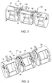
FIG. 2 is a perspective disassembled view of a crossbar operatively coupled to at least one support assembly; -
FIG. 3 is a perspective view of the crossbar and a bushing of the support assembly; -
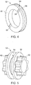
FIG. 4 is a perspective view of the bushing according to an embodiment; -
FIG. 5 is a perspective view of the bushing according to another embodiment; -
FIG. 6 is a perspective view of a support bracket of the support assembly; -
FIG. 7 is a perspective view of a base structure of the circuit breaker with the support bracket operatively coupled thereto; and -
FIG. 8 is a perspective view of the crossbar assembly with the support assembly in a fully assembled and installed condition with the base structure. - The detailed description explains embodiments of the disclosure, together with advantages and features, by way of example with reference to the drawings.
- Referring to
FIG. 1 , acircuit breaker 10 of the multi-pole variety is partially illustrated. Thecircuit breaker 10 has a cover and housing removed to better illustrate various components of thecircuit breaker 10 that are relevant to the embodiments of the disclosure described herein. Thecircuit breaker 10 includes amechanism 12 that is generally referenced withnumeral 12. Themechanism 12 includes a number of components configured to detect a hazardous or undesirable operating condition and to initiate switching thecircuit breaker 12 to a tripped or closed condition. Additionally, manual manipulation of the condition of thecircuit breaker 10 is facilitated with ahandle 14 that may be actuated by an operator. This gives the operator the ability to turn thecircuit breaker 10 "ON" to energize a protected circuit, turn the circuit breaker "OFF" to disconnect the protected circuit breaker, or reset the circuit breaker after a fault. Overall, themechanism 12 converts movement of thehandle 14 into mechanical force to operate thecircuit breaker 10. - The
circuit breaker 10 illustrated depicts a three-phase configuration, however, the embodiments disclosed herein are not limited to this configuration, such that alternative phase configurations (e.g., one-phase, two-phase, four-phase, etc.) may be employed. Specifically, three moveablecontact arm assemblies 16 are illustrated. The moveablecontact arm assemblies 16 are rotating conductors that are disposed, at least partially, within acrossbar assembly 18 that includes acrossbar 19. The crossbar extends from afirst end 20 to asecond end 22. Thefirst end 20 of thecrossbar 19 is operatively coupled to afirst bracket 24 located on afirst side 26 of thecircuit breaker 10. Similarly, thesecond end 22 of thecrossbar 19 is operatively coupled to asecond bracket 28 located on asecond side 30 of thecircuit breaker 10. Thefirst end 20 and thesecond end 22 are rotatably coupled to therespective brackets crossbar 19, such as with pin joint connections. - In operation, the
crossbar 19 rotates upon actuation from themechanism 12 to either drive the moveablecontact arm assemblies 16 into a position that either renders the circuit breaker in the "ON" condition, the "OFF" condition, or the "TRIP" condition. Specifically, in the event an operator manually turns thecircuit breaker 10 on, themechanism 12 interacts with thecrossbar 19, which drives the moveablecontact arm assemblies 16 into a closed position. In the event an operator manually turns thecircuit breaker 10 off, or if the mechanism automatically initiates a tripping sequence, themechanism 12 interacts with thecrossbar 19, which pulls the moveable contact arm assemblies into an open position. - The
crossbar 19 includes multiple segments that are operatively coupled to the moveablecontact arm assemblies 16. In the illustrated embodiment with three moveable contact arm assemblies, afirst segment 32, asecond segment 34 and athird segment 36 are included to correspond to the number of moveable contact arm assemblies. In such an embodiment, thefirst segment 32 is associated with a first moveablecontact arm assembly 38, a second moveablecontact arm assembly 40 and a third moveablecontact arm assembly 42. Disposed between each pair of segments is at least one coupling segment of thecrossbar 19. In the illustrated embodiment, afirst coupling segment 44 is disposed between thefirst segment 32 and thesecond segment 34 of thecrossbar 19, and therefore between the first moveablecontact arm assembly 38 and the second moveablecontact arm assembly 40. Similarly, asecond coupling segment 46 is disposed between thesecond segment 34 and thethird segment 36 of thecrossbar 19, and therefore between the second moveablecontact arm assembly 40 and the third moveablecontact arm assembly 42. As noted above, the number of segments and moveable contact arm assemblies may vary depending upon the particular circuit breaker and as a result it is to be appreciated that the number of coupling segments may vary as well. - Referring now to
FIGS. 2 and 3 , thecrossbar 19 is illustrated in greater detail and without the moveable contact arm assemblies operatively coupled thereto. To reduce or eliminate bending of thecrossbar 19 during operation, asupport assembly 50 is provided. Thesupport assembly 50 is operatively coupled to one or more coupling segments of thecrossbar 19 and to a stationary structure, as illustrated inFIGS. 7 and8 . As will be appreciated from the description herein, thesupport assembly 50 provides a secure pivoting location for thecrossbar 19, thereby strengthening theoverall crossbar assembly 18 and reducing wear that may otherwise occur due to bending of thecrossbar 19. Thesupport assembly 50 includes abushing 52, asupport bracket 54 and a fixingbracket 56. Each of these components will be described in detail below. - For purposes of discussion a single support assembly associated with the
first coupling segment 44 will be described herein; however, as shown, more than one support assembly may be operatively coupled to the crossbar, 19. By way of example, a first support assembly and a second support assembly are shown in the illustrated embodiment. The first support assembly is operatively coupled to thefirst coupling segment 44 of thecrossbar 19 and the second support assembly is operatively coupled to thesecond coupling segment 46 of thecrossbar 19. As discussed in detail above, the number of segments of thecrossbar 19 and therefore the number of coupling segments may vary from that illustrated. There may be as little as one coupling segment or several coupling segments depending upon the particular application. Different embodiments include different numbers of support assemblies as well. For example, all of the coupling segments may include a support assembly operatively coupled thereto. Alternatively, fewer than all of the coupling segments may include a support assembly operatively coupled thereto. - Referring now to
FIGS. 3 , thecrossbar 19 is shown with only the bushing 52' of thesupport assembly 50 operatively coupled thereto. Thebushing 52 is formed of a low friction material and may be secured to thefirst coupling segment 44 in numerous suitable manners. For example, thebushing 52, may be an over-molded component, may be welded to thefirst coupling segment 44, or may be secured via mechanical fasteners. Irrespective of the precise manner in which thebushing 52 is secured to thefirst coupling segment 44, a tight, fitted relationship is established between thebushing 52 and thefirst coupling segment 44. To facilitate this relationship, features may be included to form a rigid connection. For example, the embodiment ofFIG. 4 shows at least one groove orrecess 58 in anouter face 60 of thebushing 52. The groove orrecess 58 is sized to engage one or more protrusions of thecrossbar 19 that reside therein to reduce slippage between thebushing 52 and thefirst coupling segment 44. Alternatively, or in combination with the grooves or recesses described above, one ormore protrusions 62 extending from theouter face 60 of thebushing 52 are included in the embodiment ofFIG. 5 . Thebushing 52 may include one or more protrusions on a single side or both sides, as shown. The geometry of the protrusion(s) 62 may vary and corresponds to a recess defined by thecrossbar 19. Engagement of the features discussed above establishes a tight, fitted relationship between thebushing 52 and thecrossbar 19. In some embodiments, thefirst coupling segment 44 includes acoupling segment groove 45 that is sized to at least partially fit thebushing 52 therein for further retention between the components. - The
bushing 52 includes agroove 64 that extends circumferentially around thebushing 52. Thegroove 64 is sized to receive engagement portions of thesupport bracket 54 and the fixingbracket 56 therein. The brackets are relatively stationary and thebushing 52 is configured to rotate relative to these components during rotation of thecrossbar 19, as thebushing 52 is fixed thereto and rotates with thecrossbar 19. In one embodiment, a ball bearing arrangement is displayed between thebushing 52 and one or both of the brackets to reduce friction therebetween during rotation of thebushing 52. - Referring now to
FIGS. 6 and7 , thesupport bracket 54 is illustrated in greater detail. Thesupport bracket 54 includes anengagement portion 68 that extends in a curved manner correspond to thebushing 52 that it is disposed adjacent to. It is to be appreciated that thebushing 52 and thesupport bracket 54 are in direct contact in some embodiments. In such embodiments, slight spacing may occur during operation of the circuit breaker due to dynamic tolerances. Thesupport bracket 54 is operatively coupled to astationary structure 70 in any suitable manner that rigidly fixes thesupport bracket 54 thereto. In the illustrated embodiment, thestationary structure 70 is a base structure of the circuit breaker, but it is to be appreciated that thestationary structure 70 may be a circuit breaker cover that is located over a base structure in some embodiments. For example, a mid-cover may be thestationary structure 70 that thesupport bracket 54 is operatively coupled to, but any cover is contemplated. Thesupport bracket 54 is substantially stationary due to the rigid connection to thestationary structure 70 and provides a secure support structure for thebushing 52 to be positioned upon. Consequently, thesupport bracket 54 indirectly supports thecrossbar 19 at one or more coupling segments of thecrossbar 19, thereby providing a secure point of rotation for thecrossbar 19. As described above, this may be done at more than one location along the length of thecrossbar 19. - Referring to
FIGS. 2 and8 , thesupport assembly 50 is shown in a fully assembled condition. This condition includes positioning of the fixingbracket 56 disposed adjacent to thebushing 52 and engaged with thesupport bracket 54. As with thesupport bracket 54, the fixingbracket 56 includes anengagement portion 72 that extends in a curved manner correspond to thebushing 52 that it is disposed adjacent to. It is to be appreciated that thebushing 52 and the fixingbracket 56 are in direct contact in some embodiments. In such embodiments, slight spacing may occur during operation of the circuit breaker due to dynamic tolerances. The fixingbracket 56 is operatively coupled to thesupport bracket 54 in any suitable manner and when coupled form a structure that fully surrounds a portion of thebushing 52, specifically thegroove 64 of thebushing 52 that the brackets are disposed within. - Advantageously, the
support assembly 50 provides a secure support structure for thecrossbar 19 to reduce or eliminate bending of thecrossbar 19, thereby reducing wear on thecrossbar 19. Additionally, less energy is lost due to friction and bending, which results in more available energy from the mechanism to open and close the circuit breaker. - While the disclosure is provided in detail in connection with only a limited number of embodiments, it should be readily understood that the disclosure is not limited to such disclosed embodiments. Rather, the disclosure can be modified to incorporate any number of variations, alterations, substitutions or equivalent arrangements not heretofore described, but which are commensurate with the spirit and. scope of the disclosure. Additionally, while various embodiments of the disclosure have been described, it is to be understood that the exemplary embodiment(s) may include only some of the described exemplary aspects. Accordingly, the disclosure is not to be seen as limited by the foregoing description, but is only limited by the scope of the appended claims.
Claims (15)
- A circuit breaker crossbar assembly (18) comprising:a crossbar (19) having a first segment (32) and a second segment (34), the first segment (32) and the second segment (34) each operatively coupled to a respective moveable contact arm assembly (16);a coupling segment (44) disposed between the first segment (32) and the second segment (34), the crossbar (19) and the coupling segment (44) rotatable about an axis; andat least one support assembly (50) operatively coupled to the coupling segment (44), the at least one support assembly (50) comprising:a bushing (52) coupled to the coupling segment (44) and rotatable with the crossbar (19) and the coupling segment (44);a support bracket (54) configured for affixation to a stationary structure (70) and disposed adjacent to the bushing (52), the bushing (52) rotatable relative to the support bracket (54); anda fixing bracket (56) engaged with the support bracket (54) and disposed adjacent to the bushing (52), the bushing (52) rotatable relative to the fixing bracket (56), the support bracket (54) and the fixing bracket (56) together at least partially surrounding the bushing (52).
- The circuit breaker crossbar assembly (18) of claim 1, wherein the stationary structure (70) comprises a base structure.
- The circuit breaker crossbar assembly (18) of claim 1, wherein the stationary structure (70) comprises a cover located over a base structure.
- The circuit breaker crossbar assembly (18) of claim 1, wherein the coupling segment (44) comprises a coupling segment groove (45), the bushing (52) at least partially disposed within the coupling segment groove (45).
- The circuit breaker crossbar assembly (18) of claim 1, wherein the bushing (52) comprises a bushing groove (58), the support bracket (54) and the fixing bracket (56) each comprising an engagement portion disposed within the bushing groove (58).
- The circuit breaker crossbar assembly (18) of claim 1, wherein the bushing (52) comprises at least one protrusion (62) extending from the bushing (52), the at least one protrusion (62) fixedly disposed within a recess (58) of the coupling segment (44), the recess (58) formed of a geometry corresponding to the geometry of the at least one protrusion (62).
- The circuit breaker crossbar assembly (18) of claim 1, wherein the crossbar (19) comprises at least three segments (32,34,36) each operatively coupled to a moveable contact arm assembly (16), the circuit breaker crossbar assembly (18) further comprises a plurality of coupling segments (44,46), each of the plurality of coupling segments (44,46) disposed between an adjacent pair of segments (32,34,36) of the at least three segments (32,34,36), wherein the at least one support assembly (50) comprises a single support assembly operatively coupled to one of the plurality of coupling segments (44,46), or the at least one support assembly (50) comprises a plurality of support assemblies, wherein each of the plurality of coupling segments (44,46) operatively coupled to one of the plurality of support assemblies (50), or less than all of the plurality of coupling segments (44,46) operatively coupled to one of the plurality of support assemblies (50).
- The circuit breaker crossbar assembly (18) of claim 1, further comprising a ball bearing arrangement disposed between the bushing (52) and the support bracket (54).
- A circuit breaker crossbar assembly (18) comprising:a crossbar (19) having a first segment (32), a second segment (34) and a third segment (36), each segment (32,34,36) operatively coupled to a respective moveable contact arm assembly (16);a first coupling segment (44) disposed between the first segment (32) and the second segment (34);a second coupling segment (46) disposed between the second segment (34) and the third segment (36), the crossbar (19), the first coupling segment (44) and the second coupling segment (46) rotatable about an axis;a first support assembly (50) operatively coupled to the first coupling segment (44) and comprising:a first bushing (52) coupled to the first coupling segment (44), the first bushing (52) having a protrusion (62) extending therefrom into a first coupling segment recess, the first bushing (52) including a first circumferentially extending groove (64);a first support bracket (54) configured for affixation to a stationary structure (70) and disposed in the first circumferentially extending groove (64) of the first bushing (52) to be disposed adjacent to the first bushing (52), the first bushing (52) rotatable relative to the first support bracket (54); anda first fixing bracket (56) engaged with the first support bracket (54) and disposed in the first circumferentially extending groove (64) to be disposed adjacent to the first bushing (52), the first bushing (52) rotatable relative to the first fixing bracket (56), the first support bracket (54) and the first fixing bracket (56) together at least partially surrounding the first bushing (52);a second support assembly (50) operatively coupled to the second coupling segment (46) and comprising:a second bushing coupled to the second coupling segment (46), the second bushing having a protrusion extending therefrom into a second coupling segment recess, the second bushing including a second circumferentially extending groove;a second support bracket configured for affixation to the stationary structure (70) and disposed in the second circumferentially extending groove of the second bushing to be disposed adjacent to the second bushing, the second bushing rotatable relative to the second support bracket; anda second fixing bracket engaged with the second support bracket and disposed in the second circumferentially extending groove to be disposed adjacent to the second bushing, the second bushing rotatable relative to the second fixing bracket, the second support bracket and the second fixing bracket together at least partially surrounding the second bushing.
- The circuit breaker crossbar assembly (18) of claim 9, wherein the stationary structure (70) comprises a base structure or a cover located over a base structure, wherein the first coupling segment (44) comprises a first coupling segment groove (45), the first bushing (52) at least partially disposed within the first coupling segment groove (45), the second coupling segment (46) comprising a second coupling segment groove, the second bushing at least partially disposed within the second coupling segment groove.
- The circuit breaker crossbar assembly (18) of claim 9, further comprising:a first ball bearing arrangement disposed between the first bushing (52) and the first support bracket (54); anda second ball bearing arrangement disposed between the second bushing and the second support bracket.
- A circuit breaker (10) comprising:at least one moveable contact arm assembly (16) configured to conduct current through the circuit breaker (10);a mechanism (12) configured to actuate movement of the at least one moveable contact arm assembly (16);a crossbar (19) having at least one segment (32,34,36), the crossbar (19) rotatable between a first rotational position and a second rotational position and operatively coupled to the mechanism (12) and to the at least one moveable contact arm assembly (16) to rotate the at least one moveable contact arm assembly (16);a coupling segment (44,46) disposed adjacent to the at least one segment (32,34,36), the crossbar (19) and the coupling segment (44,46) rotatable about an axis; andat least one support assembly (50) operatively coupled to the coupling segment (44,46), the at least one support assembly (50) comprising:a bushing (52) coupled to the coupling segment (44,46) and rotatable with the crossbar (19) and the coupling segment (44,46);a support bracket (54) configured for affixation to a stationary structure (70) and disposed adjacent to the bushing (52), the bushing (52) rotatable relative to the support bracket (54); anda fixing bracket (56) engaged with the support bracket (54) and disposed adjacent to the bushing (52), the bushing (52) rotatable relative to the fixing bracket (56), the support bracket (54) and the fixing bracket (56) together at least partially surrounding the bushing (52).
- The circuit breaker (10) of claim 12, wherein the stationary structure (70) that the support bracket (54) is fixed to comprises a base structure.
- The circuit breaker (10) of claim 12, wherein the stationary structure (70) that the support bracket (54) is fixed to comprises a cover located over a base structure.
- The circuit breaker (10) of claim 12, wherein the coupling segment (44,46) comprises a coupling segment groove (45), the bushing (52) at least partially disposed within the coupling segment groove (45), the bushing (52) comprising a bushing groove (58), the support bracket (54) and the fixing bracket (56) each comprising an engagement portion disposed within the bushing groove (58).
Applications Claiming Priority (1)
| Application Number | Priority Date | Filing Date | Title |
|---|---|---|---|
| US14/717,250 US9576761B2 (en) | 2015-05-20 | 2015-05-20 | Circuit breaker crossbar assembly |
Publications (2)
| Publication Number | Publication Date |
|---|---|
| EP3098823A2 true EP3098823A2 (en) | 2016-11-30 |
| EP3098823A3 EP3098823A3 (en) | 2017-01-25 |
Family
ID=56026740
Family Applications (1)
| Application Number | Title | Priority Date | Filing Date |
|---|---|---|---|
| EP16170542.1A Withdrawn EP3098823A3 (en) | 2015-05-20 | 2016-05-20 | Circuit breaker crossbar assembly |
Country Status (3)
| Country | Link |
|---|---|
| US (1) | US9576761B2 (en) |
| EP (1) | EP3098823A3 (en) |
| CN (1) | CN106169397A (en) |
Families Citing this family (1)
| Publication number | Priority date | Publication date | Assignee | Title |
|---|---|---|---|---|
| JP7446204B2 (en) | 2020-11-18 | 2024-03-08 | 三菱電機株式会社 | circuit breaker |
Family Cites Families (19)
| Publication number | Priority date | Publication date | Assignee | Title |
|---|---|---|---|---|
| US3341791A (en) | 1964-06-16 | 1967-09-12 | Square D Co | Electric circuit breaker with improved operating mechanism |
| US4733211A (en) | 1987-01-13 | 1988-03-22 | General Electric Company | Molded case circuit breaker crossbar assembly |
| US4782583A (en) | 1987-01-13 | 1988-11-08 | General Electric Company | Method of assembling a molded case circuit breaker crossbar |
| US4736174A (en) | 1987-04-23 | 1988-04-05 | General Electric Company | Molded case circuit breaker operating mechanism |
| JP2903642B2 (en) * | 1989-09-07 | 1999-06-07 | 富士電機株式会社 | Circuit breaker |
| US5025236A (en) * | 1989-09-07 | 1991-06-18 | Fuji Electric Co., Ltd. | Circuit breaker |
| US5502428A (en) * | 1995-03-30 | 1996-03-26 | Siemens Energy & Automation Inc. | Circuit breaker with one-piece crossbar including an integrally molded operating arm |
| US5726614A (en) | 1996-05-24 | 1998-03-10 | General Electric Company | Electronic trip unit conversion kit for high ampere-rated circuit breakers |
| JP2001093394A (en) * | 1999-09-28 | 2001-04-06 | Mitsubishi Electric Corp | Circuit breaker |
| US6791440B2 (en) | 2002-08-02 | 2004-09-14 | General Electric Company | Apparatus for electrically isolating circuit breaker rotor components |
| US6965292B2 (en) | 2003-08-29 | 2005-11-15 | General Electric Company | Isolation cap and bushing for circuit breaker rotor assembly |
| ITBG20050026A1 (en) * | 2005-05-13 | 2006-11-14 | Abb Service Srl | SWITCH WITH MOBILE CREW SUSPENDED |
| US7800007B2 (en) * | 2007-06-26 | 2010-09-21 | General Electric Company | Circuit breaker subassembly apparatus |
| CN101399137B (en) * | 2007-09-25 | 2011-06-29 | 浙江正泰电器股份有限公司 | Low-voltage plastic case breakers |
| US20090107819A1 (en) | 2007-10-25 | 2009-04-30 | Chandrasekhar Samudrikam | Secondary Handle Assembly and Method for Actuating a Circuit Breaker |
| CN101604600B (en) * | 2009-06-05 | 2012-10-03 | 上海诺雅克电气有限公司 | Multi-stage breaker with auxiliary supports |
| US8835782B2 (en) * | 2011-09-22 | 2014-09-16 | Abb Technology Ag | Contact arm assembly for switchgear circuit breaker having improved cooling fins and contact fingers to maximize heat rejection |
| CN103474299A (en) * | 2013-08-22 | 2013-12-25 | 宁波奇乐电气集团有限公司 | Movable conductor connecting structure of circuit breaker |
| CN204375671U (en) * | 2014-11-20 | 2015-06-03 | 浙江正泰电器股份有限公司 | Multi-pole double-break |
-
2015
- 2015-05-20 US US14/717,250 patent/US9576761B2/en not_active Expired - Fee Related
-
2016
- 2016-05-20 CN CN201610341165.4A patent/CN106169397A/en active Pending
- 2016-05-20 EP EP16170542.1A patent/EP3098823A3/en not_active Withdrawn
Non-Patent Citations (1)
| Title |
|---|
| None |
Also Published As
| Publication number | Publication date |
|---|---|
| US9576761B2 (en) | 2017-02-21 |
| US20160343528A1 (en) | 2016-11-24 |
| EP3098823A3 (en) | 2017-01-25 |
| CN106169397A (en) | 2016-11-30 |
Similar Documents
| Publication | Publication Date | Title |
|---|---|---|
| US9685280B2 (en) | Switchgear operating mechanism | |
| TW201230109A (en) | Air circuit breaker | |
| US9343256B1 (en) | Electrical switching apparatus, and indication assembly and trip cam therefor | |
| EP3291274B1 (en) | Fusion welding isolation mechanism for operating mechanism of circuit breaker | |
| CN103219205B (en) | Electric switch | |
| CN101436492B (en) | Secondary trip system for circuit breaker | |
| KR101078974B1 (en) | Driving mechanism for 4 poles circuit breaker | |
| US5272291A (en) | Dual switch actuator mechanism with Geneva drive plate and follower plates detent assembly | |
| US9576761B2 (en) | Circuit breaker crossbar assembly | |
| US6653918B1 (en) | Operating mechanism for autorecloser with series disconnector | |
| US9324528B1 (en) | Magnetic trip mechanism for circuit breaker | |
| US9852857B2 (en) | Electrical switching apparatus and contact assembly therefor | |
| US9704684B2 (en) | Circuit breaker crossbar assembly | |
| EP3107112B1 (en) | Contact system of a circuit breaker, and circuit breaker | |
| CN105489451B (en) | Switchgear with the blocking device for display switch position | |
| KR200461964Y1 (en) | Household earth leakage breaker | |
| EP2669923A1 (en) | Circuit breaker and method of tripping a circuit breaker | |
| CN104885175B (en) | Support component for the microswitch of switching device | |
| US20160240335A1 (en) | Circuit breaker crossbar assembly and method | |
| KR20090028290A (en) | Shaft assembly of wiring breaker and single-pole breaking unit with same | |
| US20150179381A1 (en) | Lever arm for a shunt trip device | |
| EP3048632A1 (en) | Method for operating a circuit breaker and circuit breaker | |
| KR20140003741U (en) | Opening apparatus of circuit breaker | |
| CN102956412A (en) | Electric switch |
Legal Events
| Date | Code | Title | Description |
|---|---|---|---|
| PUAI | Public reference made under article 153(3) epc to a published international application that has entered the european phase |
Free format text: ORIGINAL CODE: 0009012 |
|
| AK | Designated contracting states |
Kind code of ref document: A2 Designated state(s): AL AT BE BG CH CY CZ DE DK EE ES FI FR GB GR HR HU IE IS IT LI LT LU LV MC MK MT NL NO PL PT RO RS SE SI SK SM TR |
|
| AX | Request for extension of the european patent |
Extension state: BA ME |
|
| PUAL | Search report despatched |
Free format text: ORIGINAL CODE: 0009013 |
|
| AK | Designated contracting states |
Kind code of ref document: A3 Designated state(s): AL AT BE BG CH CY CZ DE DK EE ES FI FR GB GR HR HU IE IS IT LI LT LU LV MC MK MT NL NO PL PT RO RS SE SI SK SM TR |
|
| AX | Request for extension of the european patent |
Extension state: BA ME |
|
| RIC1 | Information provided on ipc code assigned before grant |
Ipc: H01H 71/02 20060101ALN20161221BHEP Ipc: H01H 9/00 20060101ALN20161221BHEP Ipc: H01H 71/10 20060101ALI20161221BHEP Ipc: H01H 1/22 20060101AFI20161221BHEP |
|
| STAA | Information on the status of an ep patent application or granted ep patent |
Free format text: STATUS: REQUEST FOR EXAMINATION WAS MADE |
|
| 17P | Request for examination filed |
Effective date: 20170725 |
|
| RBV | Designated contracting states (corrected) |
Designated state(s): AL AT BE BG CH CY CZ DE DK EE ES FI FR GB GR HR HU IE IS IT LI LT LU LV MC MK MT NL NO PL PT RO RS SE SI SK SM TR |
|
| STAA | Information on the status of an ep patent application or granted ep patent |
Free format text: STATUS: EXAMINATION IS IN PROGRESS |
|
| 17Q | First examination report despatched |
Effective date: 20180412 |
|
| RAP1 | Party data changed (applicant data changed or rights of an application transferred) |
Owner name: ABB SCHWEIZ AG |
|
| STAA | Information on the status of an ep patent application or granted ep patent |
Free format text: STATUS: THE APPLICATION IS DEEMED TO BE WITHDRAWN |
|
| 18D | Application deemed to be withdrawn |
Effective date: 20191116 |