EP3098799A1 - Method, apparatus and computer program product for lane filtering - Google Patents
Method, apparatus and computer program product for lane filtering Download PDFInfo
- Publication number
- EP3098799A1 EP3098799A1 EP15169564.0A EP15169564A EP3098799A1 EP 3098799 A1 EP3098799 A1 EP 3098799A1 EP 15169564 A EP15169564 A EP 15169564A EP 3098799 A1 EP3098799 A1 EP 3098799A1
- Authority
- EP
- European Patent Office
- Prior art keywords
- vehicle
- distance
- information
- vehicles
- lane
- Prior art date
- Legal status (The legal status is an assumption and is not a legal conclusion. Google has not performed a legal analysis and makes no representation as to the accuracy of the status listed.)
- Withdrawn
Links
Images


Classifications
-
- G—PHYSICS
- G08—SIGNALLING
- G08G—TRAFFIC CONTROL SYSTEMS
- G08G1/00—Traffic control systems for road vehicles
- G08G1/16—Anti-collision systems
- G08G1/167—Driving aids for lane monitoring, lane changing, e.g. blind spot detection
-
- B—PERFORMING OPERATIONS; TRANSPORTING
- B60—VEHICLES IN GENERAL
- B60W—CONJOINT CONTROL OF VEHICLE SUB-UNITS OF DIFFERENT TYPE OR DIFFERENT FUNCTION; CONTROL SYSTEMS SPECIALLY ADAPTED FOR HYBRID VEHICLES; ROAD VEHICLE DRIVE CONTROL SYSTEMS FOR PURPOSES NOT RELATED TO THE CONTROL OF A PARTICULAR SUB-UNIT
- B60W30/00—Purposes of road vehicle drive control systems not related to the control of a particular sub-unit, e.g. of systems using conjoint control of vehicle sub-units, or advanced driver assistance systems for ensuring comfort, stability and safety or drive control systems for propelling or retarding the vehicle
- B60W30/18—Propelling the vehicle
- B60W30/18009—Propelling the vehicle related to particular drive situations
- B60W30/18163—Lane change; Overtaking manoeuvres
-
- B—PERFORMING OPERATIONS; TRANSPORTING
- B60—VEHICLES IN GENERAL
- B60W—CONJOINT CONTROL OF VEHICLE SUB-UNITS OF DIFFERENT TYPE OR DIFFERENT FUNCTION; CONTROL SYSTEMS SPECIALLY ADAPTED FOR HYBRID VEHICLES; ROAD VEHICLE DRIVE CONTROL SYSTEMS FOR PURPOSES NOT RELATED TO THE CONTROL OF A PARTICULAR SUB-UNIT
- B60W50/00—Details of control systems for road vehicle drive control not related to the control of a particular sub-unit, e.g. process diagnostic or vehicle driver interfaces
- B60W50/08—Interaction between the driver and the control system
- B60W50/14—Means for informing the driver, warning the driver or prompting a driver intervention
-
- G—PHYSICS
- G08—SIGNALLING
- G08G—TRAFFIC CONTROL SYSTEMS
- G08G1/00—Traffic control systems for road vehicles
- G08G1/09—Arrangements for giving variable traffic instructions
- G08G1/0962—Arrangements for giving variable traffic instructions having an indicator mounted inside the vehicle, e.g. giving voice messages
- G08G1/0965—Arrangements for giving variable traffic instructions having an indicator mounted inside the vehicle, e.g. giving voice messages responding to signals from another vehicle, e.g. emergency vehicle
-
- G—PHYSICS
- G08—SIGNALLING
- G08G—TRAFFIC CONTROL SYSTEMS
- G08G1/00—Traffic control systems for road vehicles
- G08G1/16—Anti-collision systems
- G08G1/161—Decentralised systems, e.g. inter-vehicle communication
- G08G1/163—Decentralised systems, e.g. inter-vehicle communication involving continuous checking
-
- G—PHYSICS
- G08—SIGNALLING
- G08G—TRAFFIC CONTROL SYSTEMS
- G08G1/00—Traffic control systems for road vehicles
- G08G1/16—Anti-collision systems
- G08G1/166—Anti-collision systems for active traffic, e.g. moving vehicles, pedestrians, bikes
-
- B—PERFORMING OPERATIONS; TRANSPORTING
- B60—VEHICLES IN GENERAL
- B60W—CONJOINT CONTROL OF VEHICLE SUB-UNITS OF DIFFERENT TYPE OR DIFFERENT FUNCTION; CONTROL SYSTEMS SPECIALLY ADAPTED FOR HYBRID VEHICLES; ROAD VEHICLE DRIVE CONTROL SYSTEMS FOR PURPOSES NOT RELATED TO THE CONTROL OF A PARTICULAR SUB-UNIT
- B60W2300/00—Indexing codes relating to the type of vehicle
- B60W2300/36—Cycles; Motorcycles; Scooters
-
- B—PERFORMING OPERATIONS; TRANSPORTING
- B60—VEHICLES IN GENERAL
- B60W—CONJOINT CONTROL OF VEHICLE SUB-UNITS OF DIFFERENT TYPE OR DIFFERENT FUNCTION; CONTROL SYSTEMS SPECIALLY ADAPTED FOR HYBRID VEHICLES; ROAD VEHICLE DRIVE CONTROL SYSTEMS FOR PURPOSES NOT RELATED TO THE CONTROL OF A PARTICULAR SUB-UNIT
- B60W2540/00—Input parameters relating to occupants
- B60W2540/20—Direction indicator values
-
- B—PERFORMING OPERATIONS; TRANSPORTING
- B60—VEHICLES IN GENERAL
- B60W—CONJOINT CONTROL OF VEHICLE SUB-UNITS OF DIFFERENT TYPE OR DIFFERENT FUNCTION; CONTROL SYSTEMS SPECIALLY ADAPTED FOR HYBRID VEHICLES; ROAD VEHICLE DRIVE CONTROL SYSTEMS FOR PURPOSES NOT RELATED TO THE CONTROL OF A PARTICULAR SUB-UNIT
- B60W2554/00—Input parameters relating to objects
- B60W2554/80—Spatial relation or speed relative to objects
- B60W2554/801—Lateral distance
-
- B—PERFORMING OPERATIONS; TRANSPORTING
- B60—VEHICLES IN GENERAL
- B60W—CONJOINT CONTROL OF VEHICLE SUB-UNITS OF DIFFERENT TYPE OR DIFFERENT FUNCTION; CONTROL SYSTEMS SPECIALLY ADAPTED FOR HYBRID VEHICLES; ROAD VEHICLE DRIVE CONTROL SYSTEMS FOR PURPOSES NOT RELATED TO THE CONTROL OF A PARTICULAR SUB-UNIT
- B60W2556/00—Input parameters relating to data
- B60W2556/45—External transmission of data to or from the vehicle
- B60W2556/55—External transmission of data to or from the vehicle using telemetry
-
- B—PERFORMING OPERATIONS; TRANSPORTING
- B60—VEHICLES IN GENERAL
- B60W—CONJOINT CONTROL OF VEHICLE SUB-UNITS OF DIFFERENT TYPE OR DIFFERENT FUNCTION; CONTROL SYSTEMS SPECIALLY ADAPTED FOR HYBRID VEHICLES; ROAD VEHICLE DRIVE CONTROL SYSTEMS FOR PURPOSES NOT RELATED TO THE CONTROL OF A PARTICULAR SUB-UNIT
- B60W2556/00—Input parameters relating to data
- B60W2556/45—External transmission of data to or from the vehicle
- B60W2556/65—Data transmitted between vehicles
-
- B—PERFORMING OPERATIONS; TRANSPORTING
- B60—VEHICLES IN GENERAL
- B60W—CONJOINT CONTROL OF VEHICLE SUB-UNITS OF DIFFERENT TYPE OR DIFFERENT FUNCTION; CONTROL SYSTEMS SPECIALLY ADAPTED FOR HYBRID VEHICLES; ROAD VEHICLE DRIVE CONTROL SYSTEMS FOR PURPOSES NOT RELATED TO THE CONTROL OF A PARTICULAR SUB-UNIT
- B60W2756/00—Output or target parameters relating to data
- B60W2756/10—Involving external transmission of data to or from the vehicle
-
- B—PERFORMING OPERATIONS; TRANSPORTING
- B60—VEHICLES IN GENERAL
- B60Y—INDEXING SCHEME RELATING TO ASPECTS CROSS-CUTTING VEHICLE TECHNOLOGY
- B60Y2200/00—Type of vehicle
- B60Y2200/10—Road Vehicles
- B60Y2200/12—Motorcycles, Trikes; Quads; Scooters
-
- B—PERFORMING OPERATIONS; TRANSPORTING
- B60—VEHICLES IN GENERAL
- B60Y—INDEXING SCHEME RELATING TO ASPECTS CROSS-CUTTING VEHICLE TECHNOLOGY
- B60Y2200/00—Type of vehicle
- B60Y2200/10—Road Vehicles
- B60Y2200/13—Bicycles; Tricycles
Definitions
- the present embodiments relate generally to a method for lane filtering.
- the present embodiments relate to a method for determining whether lane filtering may be performed, an apparatus for lane filtering and computer program code to implement the determination by a device.
- lane filtering relates to a situation in which someone is riding a motorcycle, or any other vehicle, at low speeds between stationary or slow moving vehicles, which are travelling in the same direction as the motorcycle rider.
- This kind of situation may also be called as lane sharing, lane splitting, stripe-riding or white-lining.
- Various embodiments of the invention include a semiconductor chip, a method, an apparatus, and a computer readable medium comprising a computer program stored therein, which are characterized by what is stated in the independent claims. Various embodiments of the invention are disclosed in the dependent claims.
- a method comprises obtaining information of a distance between a second vehicle and a third vehicle adjacent to each other and in front of a first vehicle; determining whether the distance is big enough for the first vehicle to proceed through the space between the second vehicle and the third vehicle; and providing an indication on the basis of the result of the determining.
- an apparatus comprises:
- an apparatus comprises at least one processor, memory including computer program code, the memory and the computer program code configured to, with the at least one processor, cause the apparatus to perform at least the following:
- said memory and the computer program code are configured to, with the at least one processor, cause the apparatus to obtain information of the first distance by:
- said memory and the computer program code are configured to, with the at least one processor, cause the apparatus to:
- said memory and the computer program code are configured to, with the at least one processor, cause the apparatus to perform at least one of the following:
- said memory and the computer program code are configured to, with the at least one processor, cause the apparatus to:
- said memory and the computer program code are configured to, with the at least one processor, cause the apparatus to:
- said memory and the computer program code are configured to, with the at least one processor, cause the apparatus to:
- said memory and the computer program code are configured to, with the at least one processor, cause the apparatus to:
- said memory and the computer program code are configured to, with the at least one processor, cause the apparatus to:
- said memory and the computer program code are configured to, with the at least one processor, cause the apparatus to perform said determining whether the first distance is big enough by:
- a computer program product embodied on a non-transitory computer readable medium, comprises computer program code configured to, when executed on at least one processor, cause an apparatus or a system to:
- an apparatus comprises:
- drivers of vehicles may be able to make better decisions regarding lane filtering by helping them visualizing the space immediately in front of them and further away.
- FIGS 1 and 2 illustrate an apparatus according to an embodiment.
- the apparatus 50 is an electronic device, for example a mobile terminal or a user equipment of a wireless communication system (e.g. a cellular phone, a personal digital assistant (PDA), a smartphone, a tablet computer or the like), a camera device, etc.
- a wireless communication system e.g. a cellular phone, a personal digital assistant (PDA), a smartphone, a tablet computer or the like
- the embodiments disclosed in this application can be implemented within any electronic device or apparatus which is able to receive wireless signals and perform positioning or assisting in the positioning.
- the electronic device or apparatus may be connectable to a network.
- the apparatus 50 may comprise a housing 30 for incorporating and protecting the device.
- the apparatus 50 further may comprise a display 32, for example, a liquid crystal display or any other display technology capable of displaying images and/or videos.
- the apparatus 50 may further comprise a keypad 34.
- any suitable data or user interface mechanism may be employed.
- the user interface may be implemented as a virtual keyboard or data entry system as part of a touch-sensitive display.
- the apparatus may comprise a microphone 36 or any suitable audio input which may be a digital or analogue signal input.
- the apparatus 50 may further comprise an audio output device, which may be any of the following: an earpiece 38, a speaker or an analogue audio or digital audio output connection.
- the apparatus 50 may also comprise a battery (according to another embodiment, the device may be powered by any suitable mobile energy device, such as solar cell, fuel cell or clockwork generator).
- the apparatus may comprise a camera 42 capable of recording or capturing images and/or video, or may be connected to one.
- the apparatus 50 may further comprise an infrared port for short range line of sight communication to other devices.
- the apparatus 50 may further comprise any suitable short range communication solution such as for example a Bluetooth wireless connection or a USB/firewire wired solution.
- the apparatus 50 may comprise a controller 56 or processor for controlling the apparatus.
- the controller 56 may be connected to memory 58 which, according to an embodiment, may store both data in the form of image and audio data and/or may also store instructions for implementation on the controller 56.
- the controller 56 may further be connected to codec circuitry 54 suitable for carrying out coding and decoding or audio and/or video data or assisting in coding and decoding carried out by the controller 56.
- the apparatus 50 may not comprise the codec circuitry 54.
- the apparatus 50 may further comprise a card reader 48 and a smart card 46, for example a UICC and UICC reader for providing user information and being suitable for providing authentication information for authentication and authorization of the user at a network.
- a card reader 48 and a smart card 46 for example a UICC and UICC reader for providing user information and being suitable for providing authentication information for authentication and authorization of the user at a network.
- the apparatus 50 may comprise radio interface circuitry 52 connected to the controller and suitable for generating wireless communication signals for example for communication with a cellular communications network, a wireless communications system or a wireless local area network.
- the apparatus 50 may further comprise an antenna 44 connected to the radio interface circuitry 52 for transmitting radio frequency signals generated at the radio interface circuitry 52 to other apparatus(es) and for receiving radio frequency signals from other apparatus(es).
- FIG. 3 shows a system configuration comprising a plurality of apparatuses, networks and network elements according to an embodiment.
- the system 10 comprises multiple communication devices which can communicate through one or more networks.
- the system 10 may comprise any combination of wired or wireless networks including, but not limited to a wireless cellular telephone network (such as a GSM, UMTS, CDMA network, etc.), a wireless local area network (WLAN), such as defined by any of the IEEE 802.x standards, a Bluetooth personal area network, an Ethernet local area network, a token ring local area network, a wide area network, and the internet.
- a wireless cellular telephone network such as a GSM, UMTS, CDMA network, etc.
- WLAN wireless local area network
- the system 10 may include both wired and wireless communication devices or apparatus 50 suitable for implementing present embodiments.
- the system shown in Figure 3 shows a mobile telephone network 11 and a representation of the internet 28.
- Connectivity to the internet 28 may include, but is not limited to, long range wireless connections, short range wireless connections, and various wired connections including, but not limited to, telephone lines, cable lines, power lines, and similar communication pathways.
- the example communication devices shown in the system 10 may include but are not limited to, an electronic device or apparatus 50, a combination of a personal digital assistant (PDA) and a mobile telephone 14, a PDA 16, an integrated messaging device (IMD) 18, a desktop computer 20, a notebook computer 22, a digital camera 12.
- PDA personal digital assistant
- IMD integrated messaging device
- the apparatus 50 may be stationary or mobile when carried by an individual who is moving.
- the apparatus 50 may also be located in a mode of transport.
- Some of further apparatuses may send and receive calls and messages and communicate with service providers through a wireless connection 25 to a base station 24.
- the base station 24 may be connected to a network server 26 that allows communication between the mobile telephone network 11 and the internet 28.
- the system may include additional communication devices and communication devices of various types.
- the communication devices may communicate using various transmission technologies including, but not limited to, code division multiple access (CDMA), global systems for mobile communications (GSM), universal mobile telephone system (UMTS), time divisional multiple access (TDMA), frequency division multiple access (FDMA), transmission control protocol-internet protocol (TCP-IP), short messaging service (SMS), multimedia messaging service (MMS), email, instant messaging service (IMS), Bluetooth, IEEE 802.11 and any similar wireless communication technology.
- CDMA code division multiple access
- GSM global systems for mobile communications
- UMTS universal mobile telephone system
- TDMA time divisional multiple access
- FDMA frequency division multiple access
- TCP-IP transmission control protocol-internet protocol
- SMS short messaging service
- MMS multimedia messaging service
- email instant messaging service
- IMS instant messaging service
- Bluetooth IEEE 802.11 and any similar wireless communication technology.
- a communications device involved in implementing various embodiments of the present invention may communicate using various media including, but not limited to, radio infrared, laser, cable connections or any suitable connection.
- the apparatus 300 may be part of the apparatus of Figures 1 and 2 or may be separate from it, wherein the apparatus 300 may utilize some elements of the apparatus of Figure 1 and 2 .
- the controller 302 may take care of controlling the operation of the device 300 or some parts of the device 300.
- the memory 304 may be used to store information, program code and/or other data.
- the communication interface 306 may be used to communicate with other devices, such as with the server 26, 610, with the access points 103, etc.
- the positioning receiver 314 may utilize signals from positioning satellites, signals of wireless local area network, signals of a cellular network, and/or some other signals in determining the location of the apparatus 300.
- the apparatus 300 may also comprise a communication transceiver 308 adapted to communicate with other vehicles to obtain information from the other vehicles and/or to send information to the other vehicles, as will be described later in this specification.
- the apparatus 50 may comprise an interface 312 for one or more proximity sensors 310.
- the proximity sensor(s) may measure distance of the vehicle to other vehicles nearby, e.g. to a vehicle beside and/or ahead of the vehicle.
- Figure 4 also illustrates some operational blocks for performing a method for lane filtering, in accordance with an embodiment.
- the distance determination block 320 may estimate or obtain information on distance from the vehicle 500 to other vehicles 502 and/or distance between two adjacent vehicles V1a, V1 b; V2a, V2b (block 420 in Figure 10 ).
- the lane filtering determination block 322 may use gathered information to determine whether lane filtering is possible (block 422 in Figure 10 ).
- the information provisioning block 324 provides information regarding lane filtering to a user interface, for example to the display 32 and/or to the earpiece 38 of the apparatus 50 (block 424 in Figure 10 ).
- the display 32 may be a head up display (HUD), which is any transparent display that presents data without requiring users to look away from their viewpoints.
- the display 32 may be a head-mounted display or helmet-mounted display, where the display element moves with the orientation of the user's head.
- the apparatus 300 may comprise its own user interface 316, wherein the apparatus 300 may not need to provide lane filtering information to the apparatus 50.
- the vehicle 500 is a motorcycle and a person is riding the motorcycle on a road 504.
- the vehicle need not be a motorcycle but may be, for example, a bicycle, a car, a truck, a lorry, etc.
- the motorcycle may be able to pass by the whole queue V1a, V2a, V3a; V1 b, V2b, V3b.
- Figure 6c illustrates an example in which the driver is recommended to stop before vehicles V2a, V2b due to missing space just before the bottleneck between vehicles V3a, V3b.
- the successive vehicles V2a and V3a of the first queue and/or the successive vehicles V2b and V3b of the second queue are so close to each other that it might not be safe enough for the vehicle 500
- the apparatus 300 may be provided with information on the road 504 in the neighbourhood of the apparatus 300, such as a map, in a digital form (block 402 in Figure 5 ).
- the information may have been downloaded beforehand or it may be downloaded in real time i.e. during the riding of the vehicle.
- the positioning receiver 314 may receive signals from positioning satellites to determine the current location of the vehicle 500 (block 404), wherein the controller 302 may use the location information and the map to produce visible information of the current location and a corresponding section of the map on the display 32.
- the controller 302 may also calculate the current speed of the vehicle 500, for example by using several consecutive location data and time data, or the positioning receiver 314 may perform the speed calculation and provide that information to the processor 302.
- the map information may comprise information on the number of lanes 504a-504d and the width of the lanes 504a-504d of the road 504 at the current location.
- the map information may also comprise information on road signs and/or some other information regarding the road, such as a speed limit.
- information regarding the road may comprise information of conditions of the road, such as whether there is a construction work going on or not, the material of the surface of the road etc.
- This kind of information may be obtained by receiving road condition data from an information centre.
- Examples of this kind of services are a radio broadcast data system (RBDS) and a traffic message channel (TMC).
- the traffic message channel (TMC) may utilise the radio broadcast data system.
- the apparatus 300 of the vehicle 500 may receive information from other vehicles 502 (block 406), which are in the proximity of the vehicle 500.
- the apparatus 300 may receive information from one or more vehicles ahead of and which are proceeding the same direction and on the same road 504 than the vehicle 500. That information may comprise information of the distance between two adjacent vehicles which defines the free space i.e. the width usable for lane filtering. However, some security marginal may be applied so that there is enough space for the vehicle between two vehicles to pass them by safely enough.
- the driver of the vehicle 500 may manually set a value to a parameter which indicates a minimum distance the driver wishes to have between two vehicles before s/he may utilise lane filtering.
- the other vehicle may be a bike, a motorcycle, a car, a truck, a lorry, a bus, etc.
- Information on the vehicles may comprise dimensions of the vehicles (static vehicle data). This dimension information may be utilised, for example, in determining the space between two adjacent vehicles. However, if the dimension information is not available for one or more vehicles, information on the distance from one vehicle to another vehicle may be obtained on the basis of measurements performed by one or more of the vehicles in question.
- the apparatus 300 may also obtain information regarding the distance from the vehicle 500 to the nearest vehicle in the queue(s). This information may be obtained e.g. by a distance sensor 520 of the vehicle 500 and/or from location information which may be received from vehicles in the queue(s), from cloud, etc. For example, the distance between the vehicle 500 and one or more vehicles in the queue can be measured by one or more front facing sensors on the vehicle 500 (e.g. proximity sensor(s)). As another example, sensors of one or more vehicles involved may obtain information on the distance between vehicles and communicate this information to the vehicle 500. This kind of communication may be called as vehicle-to-vehicle (V2V) communication.
- V2V vehicle-to-vehicle
- sensors of one or more vehicles involved may obtain information on the distance between vehicles and communicate this information to a cloud, wherein the vehicle 500 may request this information from the cloud. It may also be possible to determine distances between vehicles by utilising position data of the vehicles.
- the vehicles may comprise a positioning receiver which sequentially determines the position of the vehicle and the position information may then be sent to a cloud and/or to other vehicles in the vicinity.
- the other vehicles may obtain the position information of other vehicles and use that information together with the position information of the vehicle itself to determine locations of other vehicles and distances between different vehicles. Position information may further be used to determine speed of other vehicles.
- the distance information may also be obtained by using one or more cameras in the vehicle 500, wherein the image information captured by the one or more cameras may be used in estimating the distance. Furthermore, image information captured by the cameras may also be used to determine possible queues in the road.
- the apparatus 300 may also use information of speed of the vehicle 500 and/or speed of vehicle(s) 502 in the queue to determine whether the vehicle 500 is approaching the queue and if so, how fast the vehicle 500 is about to reach the queue. The result of the determination may be used to estimate whether the lane filtering may become an issue or not (block 408).
- Speed information of the vehicle 500 may be obtained from a speedometer of the vehicle 500, by utilising the positioning information of the vehicle 500, etc.
- Speed information of other vehicle(s) may be gathered by communicating with the vehicle(s) in the queue, from a cloud, etc.
- the apparatus 300 may form indication about the situation to the user e.g. as a visual information by the display, as an audible information by the loudspeaker, as vibrations and/or by using other appropriate means.
- the apparatus 300 may indicate the distance how long the vehicle 500 could lane filter before the width of the free space became too narrow for lane filtering (block 410). Thus, the driver may then decide on the basis of this information whether to lane filter or not.
- the lane filtering operation may be set e.g. automatically when the apparatus 300 determines that the vehicle 500 is approaching a queue. Instead of or in addition to the automatic initiation, the lane filtering operation may be set manually by the driver of the vehicle 500.
- the apparatus 300 may determine whether there is enough space for a bike to go between two vehicles, whether this is considered safe and whether there is a proper space to possibly stop after those vehicles. For example in the example situation of Figure 6b , the apparatus 300 may determine that the vehicle 500 may perform lane filtering to pass two last vehicles V1 a, V1 b, V2a, V2b of the two adjacent queues but the next vehicles V3a, V3b are two close to each other for lane filtering. Hence, the apparatus 300 may provide a corresponding indication to the driver.
- the lane filtering operation may only be enabled when the speed of the vehicle 500 is less than a threshold, e.g. 30 km/h. This restriction may depend on local regulations and/or security issues so that possible risks of the lane filtering are not too high.
- the information gathered from the vehicle(s) may also be used to determine if there is a free lane, wherein the driver may change to such a lane well in advance instead of trying to lane filter.
- the driver of the vehicle 500 may consider changing a lane, wherein the driver may switch a blinker of the vehicle 500 on.
- the apparatus 300, the server 610 or other entity may determine whether another lane 504a, 504b in the same direction of the road 504 is free and/or if lane filtering might be possible between vehicles on other lanes of the road.
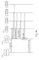
- the diagram of Figure 7a illustrates signalling regarding lane filtering between different entities of a system, in accordance with an embodiment.
- the vehicle 500 which is approaching a possible lane filtering situation may send information on the position of the vehicle 500 and some sensor data to vehicles 502 in the queue and possibly data of the dimensions of the vehicle 500. Vehicles which receive the information may send back sensor data of their own sensors, such as proximity information and/or position information.
- the vehicles in the queue may also estimate whether there is enough space at the locations of the vehicles and send the result of the estimation to the vehicle 500, wherein the vehicle 500 may use the result and show the driver whether lane filtering is possible and if so, how far in the queue.
- the method may operate as follows. Vehicles send sequentially information on their location to a server 610 in a cloud 600 ( Figure 8 ).
- the information may also comprise identification information of the vehicle which has sent the information.
- the apparatus 300 of the vehicle 500 may indicate to the server 610 that it considers lane filtering due to a queue which the vehicle 500 is approaching.
- the apparatus 300 may inform the server 610 the current location of the vehicle 500.
- the server 610 may then examine information stored in the cloud 600 to determine which vehicles are in the neighbourhood of the vehicle 500.
- the server 610 may then use location and distance information to determine whether lane filtering is possible or not and send this information to the apparatus 300 of the vehicle 500 so that the apparatus 300 may indicate the driver whether there is enough space for lane filtering or not.
- the server 610 may send location and/or distance data to the apparatus 300 of the vehicle 500 which may then perform the analyses of the data to determine possibility for lane filtering.
- operations regarding lane filtering may be mainly performed in the cloud 600 wherein the vehicles 500 may send sensor data such as location and possibly distance to other vehicles beside, in front of and/or behind, to the cloud 600. Calculations may then be performed in the cloud 600 to determine possibilities for lane filtering if a vehicle has indicated that it might consider lane filtering when space between two queues allows it.
- the diagram of Figure 7b illustrates signalling regarding lane filtering between different entities of a system utilising cloud computing, in accordance with an embodiment.
- the vehicle 500 which is approaching a possible lane filtering situation may send information on the position of the vehicle 500 and some sensor data and possibly data of the dimensions of the vehicle 500 to the server 610 in the cloud 600.
- the server 610 may send a query to vehicles in the neighbourhood to find out which vehicles are in the queue.
- the vehicles which receive the query and are in the vicinity of the vehicle 500 may send back information on their locations to the server 610.
- the server 610 may also obtain map information of the location of the vehicle 500.
- the server 610 may then request sensor data from the vehicles and use the received sensor data to perform computations for determining if lane filtering is possible and how far.
- the server 610 may analyze the traffic ahead (maybe a certain threshold distance) based on the query from the vehicle 500, and may determine a free path (e.g. path center line, length) between vehicles 502 on adjacent and parallel lanes ahead of the vehicle 500, and safe/recommended stop/rest positions.
- a free path e.g. path center line, length
- the server 610 may inform the apparatus 300 of the vehicle 500 about the free path (just ahead, but also out of the visibility of the driver of the vehicle 500) and stop/rest positions, and the apparatus 300 may render the information to the driver based on its dynamic location.
- the server 610 may request the apparatus 300 of the vehicle 500 to keep sending sensor data to the server 610.
- operations regarding lane filtering may also be distributed amongst the apparatus 300 and the cloud 600.
- some vehicles may not be able to communicate with the cloud 600 but are able to communicate position and/or distance data to the apparatus 300 of the vehicle 500.
- the apparatus 300 may obtain vehicle related data partly from cloud and partly from vehicle(s) directly.
- operations regarding lane filtering may also be performed utilizing so called edge computing.
- some parts of the computing may be performed in a communication network which the apparatus 300 is communicating with.
- the apparatus 300 may be communicating with an access point (AP) 620 of a mobile communication network, wherein the access point 620, such as a base station, may take part of the computing operations.
- AP access point
- the access point 620 such as a base station
- the vehicle 500 which gathers and utilises the gathered information is an emergency vehicle, such as an ambulance, a fire engine, a police car, etc.
- the emergency vehicle may utilize the information regarding positions of the vehicles and the free space between two adjacent vehicles to determine whether the emergency vehicle is able to drive forward via the space between two adjacent queues. Additionally, the information may reveal whether there is enough space outside the lanes of the road, e.g. in the shoulder of the road.
- the system described above may also be utilised to send information from the vehicle 500, which considers lane filtering, to vehicles in the queues. This may be performed, for example, to warn drivers of other vehicles of the approaching motorcycle which performs lane filtering, or to warn drivers of other vehicles of the approaching emergency vehicle so that drivers may try to sidestep and increase the free space between queues.
- the system described above may also be utilised to send information from the vehicle 500 regarding intended behaviour of the driver of the vehicle.
- the driver may indicate to the apparatus 300 that s/he has decided to lane filter to the point which the apparatus 300 indicated is a safe location to stop, e.g. before a bottleneck between vehicles V2a, V2b in the example of Figure 6c .
- the apparatus 300 may send corresponding information to the vehicles V1 a, V2a, V3a, V1 b, V2b, V3b which may inform their drivers about the lane filtering accordingly.
- the vehicle 500 may gather information about vehicles in front to determine those vehicles' parameters, such as location, direction, speed, type (e.g. width), identification information etc. to know if the vehicle 500 can lane filter.
- This information may be sent to the cloud 600 where e.g. the server 610 may analyze traffic ahead based on the sensor data and may determine a free path (e.g. path center line, length) between vehicles on adjacent and parallel lanes ahead of the vehicle 500.
- the server 610 may then inform the vehicle 500 about the free path (just ahead) and the vehicle 500 may render the information to the driver based on its dynamic location.
- the system may also be used to check if there is a reserved area in front of a traffic light.
- the map information may reveal that the vehicle 500 is approaching a cross roads and if the cross roads has an area (a lane) in front of the traffic lights reserved for cycles, motorcycles etc. If it is detected that there is such a lane, then the system could guide the user till the front but if there is none or if it is full, then the system may consider it in the related guidance commands given to the user.
- a device may comprise circuitry and electronics for handling, receiving and transmitting data, computer program code in a memory, and a processor that, when running the computer program code, causes the device to carry out the features of an embodiment.
- a network device like a server may comprise circuitry and electronics for handling, receiving and transmitting data, computer program code in a memory, and a processor that, when running the computer program code, causes the network device to carry out the features of an embodiment.
- Figure 5 is an example flowchart of a method according to an example embodiments. It will be understood that each block of the flowchart, and combinations of blocks in the flowchart, may be implemented by various means, such as hardware, firmware, processor, circuitry and/or other device associated with execution of software including one or more computer program instructions.
- one or more of the procedures described above may be embodied by computer program instructions.
- the computer program instructions which embody the procedures described above may be stored by a memory device 304 of an apparatus 300 employing an embodiment of the present invention and executed by a processor 302 in the apparatus.
- any such computer program instructions may be loaded onto a computer or other programmable apparatus (e.g., hardware) to produce a machine, such that the resulting computer or other programmable apparatus embody a mechanism for implementing the functions specified in the flowchart blocks.
- These computer program instructions may also be stored in a non-transitory computer-readable storage memory (as opposed to a transmission medium such as a carrier wave or electromagnetic signal) that may direct a computer or other programmable apparatus to function in a particular manner, such that the instructions stored in the computer-readable memory produce an article of manufacture the execution of which implements the function specified in the flowchart blocks.
- the computer program instructions may also be loaded onto a computer or other programmable apparatus to cause a series of operations to be performed on the computer or other programmable apparatus to produce a computer-implemented process such that the instructions which execute on the computer or other programmable apparatus provide operations for implementing the functions specified in the flowchart block(s).
- the operations of Figure 5 when executed, convert a computer or processing circuitry into a particular machine configured to perform an example embodiment of the present invention.
- Figures 5 and 10 define an algorithm for configuring a computer or processing circuitry (e.g., processor) to perform an example embodiment.
- a general purpose computer may be configured to perform the functions shown in Figures 5 and 10 (e.g., via configuration of the processor), thereby transforming the general purpose computer into a particular machine configured to perform an example embodiment.
- blocks of the flowcharts support combinations of means for performing the specified functions, combinations of operations for performing the specified functions and program instructions for performing the specified functions. It will also be understood that one or more blocks of the flowcharts, and combinations of blocks in the flowcharts, can be implemented by special purpose hardware-based computer systems which perform the specified functions or operations, or combinations of special purpose hardware and computer instructions.
- certain ones of the operations above may be modified or further amplified. Furthermore, in some embodiments, additional optional operations may be included. Modifications, additions, or amplifications to the operations above may be performed in any order and in any combination.
Abstract
Description
- The present embodiments relate generally to a method for lane filtering. In particular, the present embodiments relate to a method for determining whether lane filtering may be performed, an apparatus for lane filtering and computer program code to implement the determination by a device.
- This section is intended to provide a background or context to the invention that is recited in the claims. The description herein may include concepts that could be pursued, but are not necessarily ones that have been previously conceived or pursued. Therefore, unless otherwise indicated herein, what is described in this section is not prior art to the description and claims in this application and is not admitted to be prior art by inclusion in this section.
- The term lane filtering relates to a situation in which someone is riding a motorcycle, or any other vehicle, at low speeds between stationary or slow moving vehicles, which are travelling in the same direction as the motorcycle rider. In other words, there are two or more parallel queues of vehicles, one on each lane of the road, and the motorcycle rider rides between two adjacent queues of vehicles. This kind of situation may also be called as lane sharing, lane splitting, stripe-riding or white-lining.
- It may happen that when the motorcycle rider is lane filtering the space ahead between the two queues may become so narrow that lane filtering may not be safe enough and the motorcyclist should stop at a distance before such location. It may not be easy to estimate such situations by naked eye so the motorcyclist may stop unnecessarily early or proceed too near the narrower spot.
- Various embodiments of the invention include a semiconductor chip, a method, an apparatus, and a computer readable medium comprising a computer program stored therein, which are characterized by what is stated in the independent claims. Various embodiments of the invention are disclosed in the dependent claims.
- According to a first example, a method comprises
obtaining information of a distance between a second vehicle and a third vehicle adjacent to each other and in front of a first vehicle;
determining whether the distance is big enough for the first vehicle to proceed through the space between the second vehicle and the third vehicle; and
providing an indication on the basis of the result of the determining. - According to a second example, an apparatus comprises:
- means for performing the actions of any of the method claims.
- According to a third example, an apparatus comprises at least one processor, memory including computer program code, the memory and the computer program code configured to, with the at least one processor, cause the apparatus to perform at least the following:
- obtain information of a first distance between a second vehicle and a third vehicle adjacent to each other and in front of a first vehicle;
- determine whether the first distance is big enough for the first vehicle to proceed through the space between the second vehicle and the third vehicle; and
- provide an indication on the basis of the result of the determining.
- In accordance with an example embodiment of the apparatus said memory and the computer program code are configured to, with the at least one processor, cause the apparatus to obtain information of the first distance by:
- obtaining information of a location of the second vehicle and a location of the third vehicle; and
- using the location information to determine the first distance.
- In accordance with an example embodiment of the apparatus said memory and the computer program code are configured to, with the at least one processor, cause the apparatus to:
- obtain information of a second distance between a fourth vehicle in front of the second vehicle in a first queue and a fifth vehicle in front of the third vehicle in a second queue; and
- use the first distance information and the second distance information to determine how long the first vehicle may be able to proceed through the space between the first queue and the second queue.
- In accordance with an example embodiment of the apparatus said memory and the computer program code are configured to, with the at least one processor, cause the apparatus to perform at least one of the following:
- receive the first distance information from the second vehicle;
- receive the second distance information from the fourth vehicle.
- In accordance with an example embodiment of the apparatus said memory and the computer program code are configured to, with the at least one processor, cause the apparatus to:
- receive the result of the determining from a server of a cloud computing network.
- In accordance with an example embodiment of the apparatus said memory and the computer program code are configured to, with the at least one processor, cause the apparatus to:
- receive a lane filtering information from a driver of the first vehicle regarding whether to proceed through a space between adjacent vehicles; and
- send the lane filtering information to one or more other vehicles in front of the first vehicle.
- In accordance with an example embodiment of the apparatus said memory and the computer program code are configured to, with the at least one processor, cause the apparatus to:
- determine whether the first vehicle is approaching at least one of the second vehicle and the third vehicle; and if so, how fast, to decide whether to perform said obtaining information of a first distance, determining whether the first distance is big enough, and providing said indication.
- In accordance with an example embodiment of the apparatus said memory and the computer program code are configured to, with the at least one processor, cause the apparatus to:
- obtain information on dimensions of one or more the first vehicle and the second vehicle; and
- use the dimensions information in determining whether the first distance is big enough for the first vehicle to proceed through the space between the second vehicle and the third vehicle.
- In accordance with an example embodiment of the apparatus said memory and the computer program code are configured to, with the at least one processor, cause the apparatus to:
- determine whether a blinker of the vehicle has been switched on; and
- if so, to examine whether another lane in the same direction of the road is free and/or if lane filtering might be possible between vehicles on other lanes of the road.
- In accordance with an example embodiment of the apparatus said memory and the computer program code are configured to, with the at least one processor, cause the apparatus to perform said determining whether the first distance is big enough by:
- comparing the first distance with a predetermined minimum distance value; and
- if the first distance is larger than the minimum distance, deducing that the space between the second vehicle and the third vehicle is big enough for the first vehicle to proceed through the space between the second vehicle and the third vehicle.
- According to a fourth example, a computer program product embodied on a non-transitory computer readable medium, comprises computer program code configured to, when executed on at least one processor, cause an apparatus or a system to:
- obtain information of a first distance between a second vehicle and a third vehicle adjacent to each other and in front of a first vehicle;
- determine whether the first distance is big enough for the first vehicle to proceed through the space between the second vehicle and the third vehicle; and
- provide an indication on the basis of the result of the determining.
- According to a fifth example, an apparatus comprises:
- means for obtaining information of a first distance between a second vehicle and a third vehicle adjacent to each other and in front of a first vehicle;
- means for determining whether the first distance is big enough for the first vehicle to proceed through the space between the second vehicle and the third vehicle; and
- means for providing an indication on the basis of the result of the determining.
- In accordance with an embodiment, drivers of vehicles may be able to make better decisions regarding lane filtering by helping them visualizing the space immediately in front of them and further away.
- In the following, various embodiments of the invention will be described in more detail with reference to the appended drawings, in which
- Figure 1
- shows an apparatus according to an embodiment;
- Figure 2
- shows a layout of an apparatus according to an embodiment;
- Figure 3
- shows a system according to an embodiment;
- Figure 4
- shows an example of an apparatus, in accordance with an embodiment;
- Figure 5
- illustrates an embodiment of a method as a flowchart;
- Figures 6a to 6c
- illustrate in a simplified manner example situations regarding lane filtering;
- Figures 7a and 7b
- illustrate examples of information exchange between different entities;
- Figure 8
- illustrates a system in accordance with an embodiment;
- Figure 9
- illustrates a system in accordance with yet another embodiment; and
- Figure 10
- illustrates an embodiment of a method as a flowchart, in accordance with an embodiment.
-
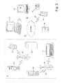
Figures 1 and 2 illustrate an apparatus according to an embodiment. Theapparatus 50 is an electronic device, for example a mobile terminal or a user equipment of a wireless communication system (e.g. a cellular phone, a personal digital assistant (PDA), a smartphone, a tablet computer or the like), a camera device, etc. The embodiments disclosed in this application can be implemented within any electronic device or apparatus which is able to receive wireless signals and perform positioning or assisting in the positioning. The electronic device or apparatus may be connectable to a network. Theapparatus 50 may comprise ahousing 30 for incorporating and protecting the device. Theapparatus 50 further may comprise adisplay 32, for example, a liquid crystal display or any other display technology capable of displaying images and/or videos. Theapparatus 50 may further comprise akeypad 34. According to another embodiment, any suitable data or user interface mechanism may be employed. For example, the user interface may be implemented as a virtual keyboard or data entry system as part of a touch-sensitive display. The apparatus may comprise amicrophone 36 or any suitable audio input which may be a digital or analogue signal input. Theapparatus 50 may further comprise an audio output device, which may be any of the following: anearpiece 38, a speaker or an analogue audio or digital audio output connection. Theapparatus 50 may also comprise a battery (according to another embodiment, the device may be powered by any suitable mobile energy device, such as solar cell, fuel cell or clockwork generator). The apparatus may comprise acamera 42 capable of recording or capturing images and/or video, or may be connected to one. According to an embodiment, theapparatus 50 may further comprise an infrared port for short range line of sight communication to other devices. According to an embodiment, theapparatus 50 may further comprise any suitable short range communication solution such as for example a Bluetooth wireless connection or a USB/firewire wired solution. - The
apparatus 50 may comprise acontroller 56 or processor for controlling the apparatus. Thecontroller 56 may be connected tomemory 58 which, according to an embodiment, may store both data in the form of image and audio data and/or may also store instructions for implementation on thecontroller 56. Thecontroller 56 may further be connected tocodec circuitry 54 suitable for carrying out coding and decoding or audio and/or video data or assisting in coding and decoding carried out by thecontroller 56. However, theapparatus 50 may not comprise thecodec circuitry 54. - The
apparatus 50 may further comprise acard reader 48 and asmart card 46, for example a UICC and UICC reader for providing user information and being suitable for providing authentication information for authentication and authorization of the user at a network. - The
apparatus 50 may compriseradio interface circuitry 52 connected to the controller and suitable for generating wireless communication signals for example for communication with a cellular communications network, a wireless communications system or a wireless local area network. Theapparatus 50 may further comprise anantenna 44 connected to theradio interface circuitry 52 for transmitting radio frequency signals generated at theradio interface circuitry 52 to other apparatus(es) and for receiving radio frequency signals from other apparatus(es). -
Figure 3 shows a system configuration comprising a plurality of apparatuses, networks and network elements according to an embodiment. Thesystem 10 comprises multiple communication devices which can communicate through one or more networks. Thesystem 10 may comprise any combination of wired or wireless networks including, but not limited to a wireless cellular telephone network (such as a GSM, UMTS, CDMA network, etc.), a wireless local area network (WLAN), such as defined by any of the IEEE 802.x standards, a Bluetooth personal area network, an Ethernet local area network, a token ring local area network, a wide area network, and the internet. - The
system 10 may include both wired and wireless communication devices orapparatus 50 suitable for implementing present embodiments. For example, the system shown inFigure 3 shows amobile telephone network 11 and a representation of theinternet 28. Connectivity to theinternet 28 may include, but is not limited to, long range wireless connections, short range wireless connections, and various wired connections including, but not limited to, telephone lines, cable lines, power lines, and similar communication pathways. - The example communication devices shown in the
system 10 may include but are not limited to, an electronic device orapparatus 50, a combination of a personal digital assistant (PDA) and amobile telephone 14, aPDA 16, an integrated messaging device (IMD) 18, adesktop computer 20, anotebook computer 22, adigital camera 12. Theapparatus 50 may be stationary or mobile when carried by an individual who is moving. Theapparatus 50 may also be located in a mode of transport. - Some of further apparatuses may send and receive calls and messages and communicate with service providers through a
wireless connection 25 to abase station 24. Thebase station 24 may be connected to anetwork server 26 that allows communication between themobile telephone network 11 and theinternet 28. The system may include additional communication devices and communication devices of various types. - The communication devices may communicate using various transmission technologies including, but not limited to, code division multiple access (CDMA), global systems for mobile communications (GSM), universal mobile telephone system (UMTS), time divisional multiple access (TDMA), frequency division multiple access (FDMA), transmission control protocol-internet protocol (TCP-IP), short messaging service (SMS), multimedia messaging service (MMS), email, instant messaging service (IMS), Bluetooth, IEEE 802.11 and any similar wireless communication technology. A communications device involved in implementing various embodiments of the present invention may communicate using various media including, but not limited to, radio infrared, laser, cable connections or any suitable connection.
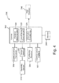
- In the following some details of an example of the
apparatus 300 for avehicle 500 or a driver of the vehicle will be described with reference toFigure 4 . Theapparatus 300 may be part of the apparatus ofFigures 1 and 2 or may be separate from it, wherein theapparatus 300 may utilize some elements of the apparatus ofFigure 1 and 2 . In this example embodiment thecontroller 302 may take care of controlling the operation of thedevice 300 or some parts of thedevice 300. Thememory 304 may be used to store information, program code and/or other data. Thecommunication interface 306 may be used to communicate with other devices, such as with theserver positioning receiver 314 may utilize signals from positioning satellites, signals of wireless local area network, signals of a cellular network, and/or some other signals in determining the location of theapparatus 300. - The
apparatus 300 may also comprise acommunication transceiver 308 adapted to communicate with other vehicles to obtain information from the other vehicles and/or to send information to the other vehicles, as will be described later in this specification. Further, theapparatus 50 may comprise aninterface 312 for one ormore proximity sensors 310. The proximity sensor(s) may measure distance of the vehicle to other vehicles nearby, e.g. to a vehicle beside and/or ahead of the vehicle. -
Figure 4 also illustrates some operational blocks for performing a method for lane filtering, in accordance with an embodiment. Thedistance determination block 320 may estimate or obtain information on distance from thevehicle 500 toother vehicles 502 and/or distance between two adjacent vehicles V1a, V1 b; V2a, V2b (block 420 inFigure 10 ). The lanefiltering determination block 322 may use gathered information to determine whether lane filtering is possible (block 422 inFigure 10 ). Theinformation provisioning block 324 provides information regarding lane filtering to a user interface, for example to thedisplay 32 and/or to theearpiece 38 of the apparatus 50 (block 424 inFigure 10 ). Thedisplay 32 may be a head up display (HUD), which is any transparent display that presents data without requiring users to look away from their viewpoints. Thedisplay 32 may be a head-mounted display or helmet-mounted display, where the display element moves with the orientation of the user's head. - In accordance with an embodiment the
apparatus 300 may comprise itsown user interface 316, wherein theapparatus 300 may not need to provide lane filtering information to theapparatus 50. - It should also be noted here that some of the
blocks 306 to 312 may be implemented as separate circuitry or as a program code of thecontroller 302 or both. - In the following a method for lane filtering according to an example embodiment will be described in more detail with reference to the flow diagrams of
Figures 5 and10 and the example situation ofFigures 6a to 6c . It is assumed that thevehicle 500 is a motorcycle and a person is riding the motorcycle on aroad 504. However, the vehicle need not be a motorcycle but may be, for example, a bicycle, a car, a truck, a lorry, etc. In the example ofFigure 6a it is assumed that the motorcycle may be able to pass by the whole queue V1a, V2a, V3a; V1 b, V2b, V3b. In the example situation ofFigure 6b it is assumed that the motorcycle may be able to pass by a couple of vehicles V1a, V2a; V1 b, V2b and can stop just before a bottleneck i.e. just before a location in which the space between two vehicles V3a, V3b is not enough for lane filtering.Figure 6c illustrates an example in which the driver is recommended to stop before vehicles V2a, V2b due to missing space just before the bottleneck between vehicles V3a, V3b. In other words, in the example situation ofFigure 6c the successive vehicles V2a and V3a of the first queue and/or the successive vehicles V2b and V3b of the second queue are so close to each other that it might not be safe enough for thevehicle 500 - The
apparatus 300 may be provided with information on theroad 504 in the neighbourhood of theapparatus 300, such as a map, in a digital form (block 402 inFigure 5 ). The information may have been downloaded beforehand or it may be downloaded in real time i.e. during the riding of the vehicle. Thepositioning receiver 314 may receive signals from positioning satellites to determine the current location of the vehicle 500 (block 404), wherein thecontroller 302 may use the location information and the map to produce visible information of the current location and a corresponding section of the map on thedisplay 32. Thecontroller 302 may also calculate the current speed of thevehicle 500, for example by using several consecutive location data and time data, or thepositioning receiver 314 may perform the speed calculation and provide that information to theprocessor 302. - The map information may comprise information on the number of
lanes 504a-504d and the width of thelanes 504a-504d of theroad 504 at the current location. The map information may also comprise information on road signs and/or some other information regarding the road, such as a speed limit. - In accordance with an embodiment, information regarding the road may comprise information of conditions of the road, such as whether there is a construction work going on or not, the material of the surface of the road etc. This kind of information may be obtained by receiving road condition data from an information centre. Examples of this kind of services are a radio broadcast data system (RBDS) and a traffic message channel (TMC). The traffic message channel (TMC) may utilise the radio broadcast data system.
- The
apparatus 300 of thevehicle 500 may receive information from other vehicles 502 (block 406), which are in the proximity of thevehicle 500. For example, theapparatus 300 may receive information from one or more vehicles ahead of and which are proceeding the same direction and on thesame road 504 than thevehicle 500. That information may comprise information of the distance between two adjacent vehicles which defines the free space i.e. the width usable for lane filtering. However, some security marginal may be applied so that there is enough space for the vehicle between two vehicles to pass them by safely enough. In accordance with an embodiment, the driver of thevehicle 500 may manually set a value to a parameter which indicates a minimum distance the driver wishes to have between two vehicles before s/he may utilise lane filtering. - The other vehicle may be a bike, a motorcycle, a car, a truck, a lorry, a bus, etc.
- Information on the vehicles may comprise dimensions of the vehicles (static vehicle data). This dimension information may be utilised, for example, in determining the space between two adjacent vehicles. However, if the dimension information is not available for one or more vehicles, information on the distance from one vehicle to another vehicle may be obtained on the basis of measurements performed by one or more of the vehicles in question.
- The
apparatus 300 may also obtain information regarding the distance from thevehicle 500 to the nearest vehicle in the queue(s). This information may be obtained e.g. by a distance sensor 520 of thevehicle 500 and/or from location information which may be received from vehicles in the queue(s), from cloud, etc. For example, the distance between thevehicle 500 and one or more vehicles in the queue can be measured by one or more front facing sensors on the vehicle 500 (e.g. proximity sensor(s)). As another example, sensors of one or more vehicles involved may obtain information on the distance between vehicles and communicate this information to thevehicle 500. This kind of communication may be called as vehicle-to-vehicle (V2V) communication. As a yet another example, sensors of one or more vehicles involved may obtain information on the distance between vehicles and communicate this information to a cloud, wherein thevehicle 500 may request this information from the cloud. It may also be possible to determine distances between vehicles by utilising position data of the vehicles. For example, the vehicles may comprise a positioning receiver which sequentially determines the position of the vehicle and the position information may then be sent to a cloud and/or to other vehicles in the vicinity. Thus, the other vehicles may obtain the position information of other vehicles and use that information together with the position information of the vehicle itself to determine locations of other vehicles and distances between different vehicles. Position information may further be used to determine speed of other vehicles. - The distance information may also be obtained by using one or more cameras in the
vehicle 500, wherein the image information captured by the one or more cameras may be used in estimating the distance. Furthermore, image information captured by the cameras may also be used to determine possible queues in the road. - The
apparatus 300 may also use information of speed of thevehicle 500 and/or speed of vehicle(s) 502 in the queue to determine whether thevehicle 500 is approaching the queue and if so, how fast thevehicle 500 is about to reach the queue. The result of the determination may be used to estimate whether the lane filtering may become an issue or not (block 408). Speed information of thevehicle 500 may be obtained from a speedometer of thevehicle 500, by utilising the positioning information of thevehicle 500, etc. Speed information of other vehicle(s) may be gathered by communicating with the vehicle(s) in the queue, from a cloud, etc. - The
apparatus 300 may form indication about the situation to the user e.g. as a visual information by the display, as an audible information by the loudspeaker, as vibrations and/or by using other appropriate means. For example, theapparatus 300 may indicate the distance how long thevehicle 500 could lane filter before the width of the free space became too narrow for lane filtering (block 410). Thus, the driver may then decide on the basis of this information whether to lane filter or not. - The lane filtering operation may be set e.g. automatically when the
apparatus 300 determines that thevehicle 500 is approaching a queue. Instead of or in addition to the automatic initiation, the lane filtering operation may be set manually by the driver of thevehicle 500. - By combining the gathered data, the
apparatus 300 may determine whether there is enough space for a bike to go between two vehicles, whether this is considered safe and whether there is a proper space to possibly stop after those vehicles. For example in the example situation ofFigure 6b , theapparatus 300 may determine that thevehicle 500 may perform lane filtering to pass two last vehicles V1 a, V1 b, V2a, V2b of the two adjacent queues but the next vehicles V3a, V3b are two close to each other for lane filtering. Hence, theapparatus 300 may provide a corresponding indication to the driver. - In accordance with an embodiment, the lane filtering operation may only be enabled when the speed of the
vehicle 500 is less than a threshold, e.g. 30 km/h. This restriction may depend on local regulations and/or security issues so that possible risks of the lane filtering are not too high. - In accordance with an example embodiment, the information gathered from the vehicle(s) may also be used to determine if there is a free lane, wherein the driver may change to such a lane well in advance instead of trying to lane filter.
- The driver of the
vehicle 500 may consider changing a lane, wherein the driver may switch a blinker of thevehicle 500 on. Hence, in accordance with an example embodiment, theapparatus 300, theserver 610 or other entity may determine whether anotherlane road 504 is free and/or if lane filtering might be possible between vehicles on other lanes of the road. - The diagram of
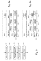
Figure 7a illustrates signalling regarding lane filtering between different entities of a system, in accordance with an embodiment. Thevehicle 500 which is approaching a possible lane filtering situation may send information on the position of thevehicle 500 and some sensor data tovehicles 502 in the queue and possibly data of the dimensions of thevehicle 500. Vehicles which receive the information may send back sensor data of their own sensors, such as proximity information and/or position information. The vehicles in the queue may also estimate whether there is enough space at the locations of the vehicles and send the result of the estimation to thevehicle 500, wherein thevehicle 500 may use the result and show the driver whether lane filtering is possible and if so, how far in the queue. - In accordance with an example embodiment the method may operate as follows. Vehicles send sequentially information on their location to a
server 610 in a cloud 600 (Figure 8 ). The information may also comprise identification information of the vehicle which has sent the information. Hence, theapparatus 300 of thevehicle 500 may indicate to theserver 610 that it considers lane filtering due to a queue which thevehicle 500 is approaching. Theapparatus 300 may inform theserver 610 the current location of thevehicle 500. Theserver 610 may then examine information stored in thecloud 600 to determine which vehicles are in the neighbourhood of thevehicle 500. Theserver 610 may then use location and distance information to determine whether lane filtering is possible or not and send this information to theapparatus 300 of thevehicle 500 so that theapparatus 300 may indicate the driver whether there is enough space for lane filtering or not. Alternatively theserver 610 may send location and/or distance data to theapparatus 300 of thevehicle 500 which may then perform the analyses of the data to determine possibility for lane filtering. - In accordance with an example embodiment, operations regarding lane filtering may be mainly performed in the
cloud 600 wherein thevehicles 500 may send sensor data such as location and possibly distance to other vehicles beside, in front of and/or behind, to thecloud 600. Calculations may then be performed in thecloud 600 to determine possibilities for lane filtering if a vehicle has indicated that it might consider lane filtering when space between two queues allows it. - The diagram of
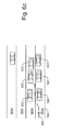
Figure 7b illustrates signalling regarding lane filtering between different entities of a system utilising cloud computing, in accordance with an embodiment. Thevehicle 500 which is approaching a possible lane filtering situation may send information on the position of thevehicle 500 and some sensor data and possibly data of the dimensions of thevehicle 500 to theserver 610 in thecloud 600. Theserver 610 may send a query to vehicles in the neighbourhood to find out which vehicles are in the queue. The vehicles which receive the query and are in the vicinity of thevehicle 500 may send back information on their locations to theserver 610. Theserver 610 may also obtain map information of the location of thevehicle 500. Theserver 610 may then request sensor data from the vehicles and use the received sensor data to perform computations for determining if lane filtering is possible and how far. For example, theserver 610 may analyze the traffic ahead (maybe a certain threshold distance) based on the query from thevehicle 500, and may determine a free path (e.g. path center line, length) betweenvehicles 502 on adjacent and parallel lanes ahead of thevehicle 500, and safe/recommended stop/rest positions. - The
server 610 may inform theapparatus 300 of thevehicle 500 about the free path (just ahead, but also out of the visibility of the driver of the vehicle 500) and stop/rest positions, and theapparatus 300 may render the information to the driver based on its dynamic location. Theserver 610 may request theapparatus 300 of thevehicle 500 to keep sending sensor data to theserver 610. - In accordance with an example embodiment, operations regarding lane filtering may also be distributed amongst the
apparatus 300 and thecloud 600. For example, some vehicles may not be able to communicate with thecloud 600 but are able to communicate position and/or distance data to theapparatus 300 of thevehicle 500. Hence, theapparatus 300 may obtain vehicle related data partly from cloud and partly from vehicle(s) directly. - In accordance with yet another example embodiment, illustrated in
Figure 9 , operations regarding lane filtering may also be performed utilizing so called edge computing. In other words, some parts of the computing may be performed in a communication network which theapparatus 300 is communicating with. As an example, theapparatus 300 may be communicating with an access point (AP) 620 of a mobile communication network, wherein theaccess point 620, such as a base station, may take part of the computing operations. Hence, all the information needed for the operations regarding lane filtering need not be transmitted to theserver 610. - In the following the method in accordance with another example embodiment will be explained in more detail. In this embodiment the
vehicle 500 which gathers and utilises the gathered information is an emergency vehicle, such as an ambulance, a fire engine, a police car, etc. Also the emergency vehicle may utilize the information regarding positions of the vehicles and the free space between two adjacent vehicles to determine whether the emergency vehicle is able to drive forward via the space between two adjacent queues. Additionally, the information may reveal whether there is enough space outside the lanes of the road, e.g. in the shoulder of the road. - In accordance with an example embodiment, the system described above may also be utilised to send information from the
vehicle 500, which considers lane filtering, to vehicles in the queues. This may be performed, for example, to warn drivers of other vehicles of the approaching motorcycle which performs lane filtering, or to warn drivers of other vehicles of the approaching emergency vehicle so that drivers may try to sidestep and increase the free space between queues. - In accordance with an example embodiment, the system described above may also be utilised to send information from the
vehicle 500 regarding intended behaviour of the driver of the vehicle. For example, the driver mat indicate to theapparatus 300 that s/he has decided to lane filter to the point which theapparatus 300 indicated is a safe location to stop, e.g. before a bottleneck between vehicles V2a, V2b in the example ofFigure 6c . Hence, theapparatus 300 may send corresponding information to the vehicles V1 a, V2a, V3a, V1 b, V2b, V3b which may inform their drivers about the lane filtering accordingly. - In accordance with an example embodiment, it may be possible to perform lane filtering determination using only sensor data available from the
vehicle 500. Sensors of thevehicle 500 may gather information about vehicles in front to determine those vehicles' parameters, such as location, direction, speed, type (e.g. width), identification information etc. to know if thevehicle 500 can lane filter. This information may be sent to thecloud 600 where e.g. theserver 610 may analyze traffic ahead based on the sensor data and may determine a free path (e.g. path center line, length) between vehicles on adjacent and parallel lanes ahead of thevehicle 500. Theserver 610 may then inform thevehicle 500 about the free path (just ahead) and thevehicle 500 may render the information to the driver based on its dynamic location. - In accordance with an example embodiment, the system may also be used to check if there is a reserved area in front of a traffic light. The map information may reveal that the
vehicle 500 is approaching a cross roads and if the cross roads has an area (a lane) in front of the traffic lights reserved for cycles, motorcycles etc. If it is detected that there is such a lane, then the system could guide the user till the front but if there is none or if it is full, then the system may consider it in the related guidance commands given to the user. - The various embodiments of the invention can be implemented with the help of computer program code that resides in a memory and causes the relevant apparatuses to carry out the invention. For example, a device may comprise circuitry and electronics for handling, receiving and transmitting data, computer program code in a memory, and a processor that, when running the computer program code, causes the device to carry out the features of an embodiment. Yet further, a network device like a server may comprise circuitry and electronics for handling, receiving and transmitting data, computer program code in a memory, and a processor that, when running the computer program code, causes the network device to carry out the features of an embodiment.
- As described above,
Figure 5 is an example flowchart of a method according to an example embodiments. It will be understood that each block of the flowchart, and combinations of blocks in the flowchart, may be implemented by various means, such as hardware, firmware, processor, circuitry and/or other device associated with execution of software including one or more computer program instructions. - For example, one or more of the procedures described above may be embodied by computer program instructions. In this regard, the computer program instructions which embody the procedures described above may be stored by a
memory device 304 of anapparatus 300 employing an embodiment of the present invention and executed by aprocessor 302 in the apparatus. As will be appreciated, any such computer program instructions may be loaded onto a computer or other programmable apparatus (e.g., hardware) to produce a machine, such that the resulting computer or other programmable apparatus embody a mechanism for implementing the functions specified in the flowchart blocks. - These computer program instructions may also be stored in a non-transitory computer-readable storage memory (as opposed to a transmission medium such as a carrier wave or electromagnetic signal) that may direct a computer or other programmable apparatus to function in a particular manner, such that the instructions stored in the computer-readable memory produce an article of manufacture the execution of which implements the function specified in the flowchart blocks. The computer program instructions may also be loaded onto a computer or other programmable apparatus to cause a series of operations to be performed on the computer or other programmable apparatus to produce a computer-implemented process such that the instructions which execute on the computer or other programmable apparatus provide operations for implementing the functions specified in the flowchart block(s). As such, the operations of
Figure 5 , when executed, convert a computer or processing circuitry into a particular machine configured to perform an example embodiment of the present invention. - Accordingly, the operations of
Figures 5 and10 define an algorithm for configuring a computer or processing circuitry (e.g., processor) to perform an example embodiment. In some cases, a general purpose computer may be configured to perform the functions shown inFigures 5 and10 (e.g., via configuration of the processor), thereby transforming the general purpose computer into a particular machine configured to perform an example embodiment. - Accordingly, blocks of the flowcharts support combinations of means for performing the specified functions, combinations of operations for performing the specified functions and program instructions for performing the specified functions. It will also be understood that one or more blocks of the flowcharts, and combinations of blocks in the flowcharts, can be implemented by special purpose hardware-based computer systems which perform the specified functions or operations, or combinations of special purpose hardware and computer instructions.
- In some embodiments, certain ones of the operations above may be modified or further amplified. Furthermore, in some embodiments, additional optional operations may be included. Modifications, additions, or amplifications to the operations above may be performed in any order and in any combination.
- Many modifications and other embodiments of the inventions set forth herein will come to mind to one skilled in the art to which these inventions pertain having the benefit of the teachings presented in the foregoing descriptions and the associated drawings. Therefore, it is to be understood that the inventions are not to be limited to the specific embodiments disclosed and that modifications and other embodiments are intended to be included within the scope of the appended claims. Although specific terms are employed herein, they are used in a generic and descriptive sense only and not for purposes of limitation.
Claims (15)
- A method comprising:obtaining information of a first distance between a second vehicle and a third vehicle adjacent to each other and in front of a first vehicle;determining whether the first distance is big enough for the first vehicle to proceed through the space between the second vehicle and the third vehicle; andproviding an indication on the basis of the result of the determining.
- The method according to claim 1 said obtaining information comprising:obtaining information of a location of the second vehicle and a location of the third vehicle; andusing the location information to determine the first distance.
- The method according to claim 1 or 2 comprising:obtaining information of a second distance between a fourth vehicle in front of the second vehicle in a first queue and a fifth vehicle in front of the third vehicle in a second queue; andusing the first distance information and the second distance information to determine how long the first vehicle may be able to proceed through the space between the first queue and the second queue.
- The method according to claim 1, 2 or 3, said obtaining information comprising one or more of the following:measuring the first distance by a distance measuring apparatus of the second vehicle;measuring the second distance by a distance measuring apparatus of the fourth vehicle.
- The method according to claim 4 comprising one or more of the following:sending the distance information to the first vehicle;sending the distance information to a communication network.
- The method according to any of the claims 1 to 5 comprising:providing at least the first distance information to a server in a cloud computing network; andperforming the determining by the server.
- The method according to any of the claims 1 to 6 comprising:receiving a lane filtering information from a driver of the first vehicle regarding whether to proceed through a space between adjacent vehicles; andsending the lane filtering information to one or more other vehicles in front of the first vehicle.
- The method according to any of the claims 1 to 7 comprising:determining whether the first vehicle is approaching at least one of the second vehicle and the third vehicle; and if so, how fast, to decide whether to perform said obtaining information of a first distance, determining whether the first distance is big enough, and providing said indication.
- The method according to any of the claims 1 to 8 comprising:determining whether the first vehicle is approaching at least one of the second vehicle and the third vehicle; and if so, how fast, to decide whether to perform said obtaining information of a first distance, determining whether the first distance is big enough, and providing said indication.
- The method according to any of the claims 1 to 9 comprising:obtaining information on dimensions of one or more the first vehicle and the second vehicle; andusing the dimensions information in determining whether the first distance is big enough.
- The method according to any of the claims 1 to 10 comprising:sequentially receiving by a server location information on one or more vehicles;receiving by the server at least:wherein the method further comprises:indication from one of the one or more vehicles that the vehicle is about to lane filter due to a queue which the vehicle is approaching; andthe current location of the vehicle;examining by the server which of the one or more vehicles are in the neighbourhood of the vehicle, which is about to is about to lane filter, by using the location information to determine whether lane filtering is possible or not; andsending information whether lane filtering is possible or not to the vehicle, which is about to is about to lane filter.
- The method according to any of the claims 1 to 11 comprising:determining whether a blinker of the vehicle has been switched on; andif so, examining whether another lane in the same direction of the road is free and/or if lane filtering might be possible between vehicles on other lanes of the road.
- The method according to any of the claims 1 to 12, said determining whether the first distance is big enough comprising:comparing the first distance with a predetermined minimum distance value; andif the first distance is larger than the minimum distance, deducing that the space between the second vehicle and the third vehicle is big enough for the first vehicle to proceed through the space between the second vehicle and the third vehicle.
- An apparatus comprising:means for performing the actions of any of the claims 1 to 13.
- A computer program product embodied on a non-transitory computer readable medium, comprising computer program code configured to, when executed on at least one processor, cause an apparatus or a system to:obtain information of a first distance between a second vehicle and a third vehicle adjacent to each other and in front of a first vehicle;determine whether the first distance is big enough for the first vehicle to proceed through the space between the second vehicle and the third vehicle; andprovide an indication on the basis of the result of the determining.
Priority Applications (2)
| Application Number | Priority Date | Filing Date | Title |
|---|---|---|---|
| EP15169564.0A EP3098799A1 (en) | 2015-05-28 | 2015-05-28 | Method, apparatus and computer program product for lane filtering |
| US15/153,176 US9773416B2 (en) | 2015-05-28 | 2016-05-12 | Method, apparatus and computer program product for lane filtering |
Applications Claiming Priority (1)
| Application Number | Priority Date | Filing Date | Title |
|---|---|---|---|
| EP15169564.0A EP3098799A1 (en) | 2015-05-28 | 2015-05-28 | Method, apparatus and computer program product for lane filtering |
Publications (1)
| Publication Number | Publication Date |
|---|---|
| EP3098799A1 true EP3098799A1 (en) | 2016-11-30 |
Family
ID=53502416
Family Applications (1)
| Application Number | Title | Priority Date | Filing Date |
|---|---|---|---|
| EP15169564.0A Withdrawn EP3098799A1 (en) | 2015-05-28 | 2015-05-28 | Method, apparatus and computer program product for lane filtering |
Country Status (2)
| Country | Link |
|---|---|
| US (1) | US9773416B2 (en) |
| EP (1) | EP3098799A1 (en) |
Cited By (3)
| Publication number | Priority date | Publication date | Assignee | Title |
|---|---|---|---|---|
| WO2019111140A1 (en) * | 2017-12-06 | 2019-06-13 | 口—ベルト ボッシュ ゲゼルシャフト ミット べシュレンクテル ハフツング | Control system and control method for controlling behavior of motorcycle during lane splitting |
| WO2021130577A1 (en) * | 2019-12-26 | 2021-07-01 | □ベルト・ボッシュ・ゲゼルシャフト・ミト・べシュレンクテル・ハフツング | Control device and control method |
| WO2023105337A1 (en) * | 2021-12-07 | 2023-06-15 | ロベルト·ボッシュ·ゲゼルシャフト·ミト•ベシュレンクテル·ハフツング | Assistance system and control method therefor |
Families Citing this family (2)
| Publication number | Priority date | Publication date | Assignee | Title |
|---|---|---|---|---|
| RU2705885C1 (en) * | 2015-10-20 | 2019-11-12 | ФОРД ГЛОУБАЛ ТЕКНОЛОДЖИЗ, ЭлЭлСи | Controller for autonomous vehicle and method of controlling strip by autonomous vehicle |
| EP3477613B1 (en) * | 2016-06-30 | 2021-09-29 | Yamaha Hatsudoki Kabushiki Kaisha | Vehicle-to-vehicle communication apparatus |
Citations (6)
| Publication number | Priority date | Publication date | Assignee | Title |
|---|---|---|---|---|
| EP1508819A1 (en) * | 2003-08-19 | 2005-02-23 | Volkswagen Aktiengesellschaft | Driving assist system for a vehicle |
| DE102007002262A1 (en) * | 2007-01-16 | 2008-08-21 | GM Global Technology Operations, Inc., Detroit | Method for support of driver of motor vehicle near parking, involves determining parameters of detected possible parking vacancies by sensors |
| DE102007053274A1 (en) * | 2007-11-08 | 2009-05-14 | Robert Bosch Gmbh | Driver assistance system for motorized two-wheelers in particular |
| DE102012005245A1 (en) * | 2012-03-14 | 2012-09-20 | Daimler Ag | Method for assisting driver of motor vehicle by overtaking process on oppositely drivable lane, involves detecting environment size described by environment of motor vehicle |
| US8473144B1 (en) * | 2012-10-30 | 2013-06-25 | Google Inc. | Controlling vehicle lateral lane positioning |
| US20130311075A1 (en) * | 2012-05-18 | 2013-11-21 | Continental Automotive Systems, Inc. | Motorcycle and helmet providing advance driver assistance |
Family Cites Families (1)
| Publication number | Priority date | Publication date | Assignee | Title |
|---|---|---|---|---|
| US20160306357A1 (en) * | 2015-04-17 | 2016-10-20 | Delphi Technologies, Inc. | Automated vehicle system with position bias for motorcycle lane splitting |
-
2015
- 2015-05-28 EP EP15169564.0A patent/EP3098799A1/en not_active Withdrawn
-
2016
- 2016-05-12 US US15/153,176 patent/US9773416B2/en active Active
Patent Citations (6)
| Publication number | Priority date | Publication date | Assignee | Title |
|---|---|---|---|---|
| EP1508819A1 (en) * | 2003-08-19 | 2005-02-23 | Volkswagen Aktiengesellschaft | Driving assist system for a vehicle |
| DE102007002262A1 (en) * | 2007-01-16 | 2008-08-21 | GM Global Technology Operations, Inc., Detroit | Method for support of driver of motor vehicle near parking, involves determining parameters of detected possible parking vacancies by sensors |
| DE102007053274A1 (en) * | 2007-11-08 | 2009-05-14 | Robert Bosch Gmbh | Driver assistance system for motorized two-wheelers in particular |
| DE102012005245A1 (en) * | 2012-03-14 | 2012-09-20 | Daimler Ag | Method for assisting driver of motor vehicle by overtaking process on oppositely drivable lane, involves detecting environment size described by environment of motor vehicle |
| US20130311075A1 (en) * | 2012-05-18 | 2013-11-21 | Continental Automotive Systems, Inc. | Motorcycle and helmet providing advance driver assistance |
| US8473144B1 (en) * | 2012-10-30 | 2013-06-25 | Google Inc. | Controlling vehicle lateral lane positioning |
Cited By (6)
| Publication number | Priority date | Publication date | Assignee | Title |
|---|---|---|---|---|
| WO2019111140A1 (en) * | 2017-12-06 | 2019-06-13 | 口—ベルト ボッシュ ゲゼルシャフト ミット べシュレンクテル ハフツング | Control system and control method for controlling behavior of motorcycle during lane splitting |
| CN111433096A (en) * | 2017-12-06 | 2020-07-17 | 罗伯特·博世有限公司 | Control device and control method for controlling behavior of motorcycle in inter-lane traveling |
| US11364906B2 (en) | 2017-12-06 | 2022-06-21 | Robert Bosch Gmbh | Control system and control method for controlling behavior of motorcycle |
| CN111433096B (en) * | 2017-12-06 | 2024-03-26 | 罗伯特·博世有限公司 | Control device and control method for controlling behavior of motorcycle during inter-lane travel |
| WO2021130577A1 (en) * | 2019-12-26 | 2021-07-01 | □ベルト・ボッシュ・ゲゼルシャフト・ミト・べシュレンクテル・ハフツング | Control device and control method |
| WO2023105337A1 (en) * | 2021-12-07 | 2023-06-15 | ロベルト·ボッシュ·ゲゼルシャフト·ミト•ベシュレンクテル·ハフツング | Assistance system and control method therefor |
Also Published As
| Publication number | Publication date |
|---|---|
| US9773416B2 (en) | 2017-09-26 |
| US20170169710A1 (en) | 2017-06-15 |
Similar Documents
| Publication | Publication Date | Title |
|---|---|---|
| US10366605B1 (en) | Broadcasting information related to hazards impacting vehicle travel | |
| US9773416B2 (en) | Method, apparatus and computer program product for lane filtering | |
| RU2656933C2 (en) | Method and device for early warning during meeting at curves | |
| US20200098200A1 (en) | Device, Method and Computer Program for a Vehicle for Providing an Accident Notification Regarding an Accident to an Emergency Call Center | |
| TWI547913B (en) | Real-time drive assistance system and method | |
| US11017476B1 (en) | Telematics system and method for accident detection and notification | |
| JP2020087214A (en) | Information providing system, server, onboard device, program and information providing method | |
| KR20190112973A (en) | Method and Apparatus for Vulnerable Road User Protection Based on Vehicular Communication | |
| CN110293977B (en) | Method and apparatus for displaying augmented reality alert information | |
| KR20160065723A (en) | Electronic apparatus, control method of electronic apparatus, computer program and computer readable recording medium | |
| CN113170295A (en) | Virtual representation of unconnected vehicles in all-on-vehicle (V2X) system | |
| Tsukahara et al. | An Early Warning System by PoseNet for Pedestrians |
Legal Events
| Date | Code | Title | Description |
|---|---|---|---|
| PUAI | Public reference made under article 153(3) epc to a published international application that has entered the european phase |
Free format text: ORIGINAL CODE: 0009012 |
|
| AK | Designated contracting states |
Kind code of ref document: A1 Designated state(s): AL AT BE BG CH CY CZ DE DK EE ES FI FR GB GR HR HU IE IS IT LI LT LU LV MC MK MT NL NO PL PT RO RS SE SI SK SM TR |
|
| AX | Request for extension of the european patent |
Extension state: BA ME |
|
| STAA | Information on the status of an ep patent application or granted ep patent |
Free format text: STATUS: REQUEST FOR EXAMINATION WAS MADE |
|
| 17P | Request for examination filed |
Effective date: 20170228 |
|
| RBV | Designated contracting states (corrected) |
Designated state(s): AL AT BE BG CH CY CZ DE DK EE ES FI FR GB GR HR HU IE IS IT LI LT LU LV MC MK MT NL NO PL PT RO RS SE SI SK SM TR |
|
| STAA | Information on the status of an ep patent application or granted ep patent |
Free format text: STATUS: EXAMINATION IS IN PROGRESS |
|
| 17Q | First examination report despatched |
Effective date: 20200904 |
|
| STAA | Information on the status of an ep patent application or granted ep patent |
Free format text: STATUS: EXAMINATION IS IN PROGRESS |
|
| STAA | Information on the status of an ep patent application or granted ep patent |
Free format text: STATUS: EXAMINATION IS IN PROGRESS |
|
| STAA | Information on the status of an ep patent application or granted ep patent |
Free format text: STATUS: THE APPLICATION IS DEEMED TO BE WITHDRAWN |
|
| 18D | Application deemed to be withdrawn |
Effective date: 20220803 |