EP3098733A1 - Logging events with timestamps - Google Patents
Logging events with timestamps Download PDFInfo
- Publication number
- EP3098733A1 EP3098733A1 EP16160332.9A EP16160332A EP3098733A1 EP 3098733 A1 EP3098733 A1 EP 3098733A1 EP 16160332 A EP16160332 A EP 16160332A EP 3098733 A1 EP3098733 A1 EP 3098733A1
- Authority
- EP
- European Patent Office
- Prior art keywords
- timestamp
- entry
- bits
- event
- store
- Prior art date
- Legal status (The legal status is an assumption and is not a legal conclusion. Google has not performed a legal analysis and makes no representation as to the accuracy of the status listed.)
- Granted
Links
Images




Classifications
-
- G—PHYSICS
- G06—COMPUTING OR CALCULATING; COUNTING
- G06F—ELECTRIC DIGITAL DATA PROCESSING
- G06F11/00—Error detection; Error correction; Monitoring
- G06F11/30—Monitoring
- G06F11/3065—Monitoring arrangements determined by the means or processing involved in reporting the monitored data
- G06F11/3086—Monitoring arrangements determined by the means or processing involved in reporting the monitored data where the reporting involves the use of self describing data formats, i.e. metadata, markup languages, human readable formats
-
- G—PHYSICS
- G06—COMPUTING OR CALCULATING; COUNTING
- G06F—ELECTRIC DIGITAL DATA PROCESSING
- G06F11/00—Error detection; Error correction; Monitoring
- G06F11/36—Prevention of errors by analysis, debugging or testing of software
- G06F11/362—Debugging of software
- G06F11/3636—Debugging of software by tracing the execution of the program
-
- G—PHYSICS
- G06—COMPUTING OR CALCULATING; COUNTING
- G06F—ELECTRIC DIGITAL DATA PROCESSING
- G06F17/00—Digital computing or data processing equipment or methods, specially adapted for specific functions
- G06F17/40—Data acquisition and logging
-
- G—PHYSICS
- G06—COMPUTING OR CALCULATING; COUNTING
- G06F—ELECTRIC DIGITAL DATA PROCESSING
- G06F11/00—Error detection; Error correction; Monitoring
- G06F11/30—Monitoring
- G06F11/34—Recording or statistical evaluation of computer activity, e.g. of down time, of input/output operation ; Recording or statistical evaluation of user activity, e.g. usability assessment
- G06F11/3466—Performance evaluation by tracing or monitoring
-
- G—PHYSICS
- G06—COMPUTING OR CALCULATING; COUNTING
- G06F—ELECTRIC DIGITAL DATA PROCESSING
- G06F11/00—Error detection; Error correction; Monitoring
- G06F11/30—Monitoring
- G06F11/34—Recording or statistical evaluation of computer activity, e.g. of down time, of input/output operation ; Recording or statistical evaluation of user activity, e.g. usability assessment
- G06F11/3466—Performance evaluation by tracing or monitoring
- G06F11/3476—Data logging
-
- G—PHYSICS
- G06—COMPUTING OR CALCULATING; COUNTING
- G06F—ELECTRIC DIGITAL DATA PROCESSING
- G06F2201/00—Indexing scheme relating to error detection, to error correction, and to monitoring
- G06F2201/835—Timestamp
-
- G—PHYSICS
- G06—COMPUTING OR CALCULATING; COUNTING
- G06F—ELECTRIC DIGITAL DATA PROCESSING
- G06F2201/00—Indexing scheme relating to error detection, to error correction, and to monitoring
- G06F2201/86—Event-based monitoring
Definitions
- Tracing is an example of logging which is used to record information, in a trace log, about a program's execution.
- the information may, for example, be used by programmers for debugging purposes.
- the information contained in the trace log may also be used by system administrators and/or technical support personnel to diagnose problems with software.
- Some examples of events that may cause data to be stored in a trace log are: an exception being thrown by a program, reading data from a memory, changing the value of a variable, etc. Each of the events will occur at a particular time, and the trace log stores a timestamp for each event to indicate a time of the event. Therefore, by analysing the data stored in the trace log, a time flow of events in the computer system can be identified.
- the computer system also comprises other elements which may be different in different examples, but in the example shown in Figure 2 the computer system comprises a Central Processing Unit (CPU) 208, a signal processing unit 210 (e.g. a DSP), a Graphics Processing Unit (GPU) 212, the memory 214, and other devices 216, such as a display, a camera, speakers, etc., depending on the use for which the computer system is designed.
- the computer system also comprises a timing clock 218 which can be used by the logging unit 202 to determine the timestamps.
- step S910 If it is determined in step S910 that the k bits of the timestamp have wrapped then the method passes to step S912. If it is determined in step S910 that the k bits of the timestamp have not wrapped then the method passes from step S910 to step S914.
Landscapes
- Engineering & Computer Science (AREA)
- Theoretical Computer Science (AREA)
- General Engineering & Computer Science (AREA)
- Physics & Mathematics (AREA)
- General Physics & Mathematics (AREA)
- Computer Hardware Design (AREA)
- Quality & Reliability (AREA)
- Data Mining & Analysis (AREA)
- Databases & Information Systems (AREA)
- Mathematical Physics (AREA)
- Software Systems (AREA)
- Library & Information Science (AREA)
- Debugging And Monitoring (AREA)
Abstract
Description
- It is often useful to log information about events that occur in computer systems. The events could be any occurrence (e.g. an action or a process) about which information may subsequently be useful. Furthermore, the information that is logged could be of any suitable type that may be useful.
- Tracing is an example of logging which is used to record information, in a trace log, about a program's execution. The information may, for example, be used by programmers for debugging purposes. The information contained in the trace log may also be used by system administrators and/or technical support personnel to diagnose problems with software. Some examples of events that may cause data to be stored in a trace log are: an exception being thrown by a program, reading data from a memory, changing the value of a variable, etc. Each of the events will occur at a particular time, and the trace log stores a timestamp for each event to indicate a time of the event. Therefore, by analysing the data stored in the trace log, a time flow of events in the computer system can be identified.
- For each event, an entry can be stored in a store, i.e. in the trace log. As an example, the store may be configured to store 48-bit entries for events.
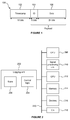
Figure 1 shows an example of anentry 100 which includes 48 bits, wherein the entry includes an 18-bit timestamp field 102, a 6-bit ID field 104 and a 24-bit data field 106. TheID field 104 and thedata field 106 may collectively be referred to as the "payload" of the entry, such that the entry includes a timestamp and a payload. When an event occurs which is to be logged, a timestamp for the event can be determined (e.g. based on a clock in the computer system). In this example, the timestamp includes 18 bits which are to be stored in thetimestamp field 102 for the event. TheID field 104 includes an indication of the processing element (e.g. a CPU, signal processing unit or other processing element within the computer system) that caused the event to occur. Thedata field 106 includes data relating to the event that occurred, e.g. to indicate that an exception has occurred, to indicate that a variable has changed its value, or any other suitable information relating to an event. - The frequency with which events occur can be different for different computer systems, and can vary over time. For example, a Digital Signal Processor (DSP) may operate, causing events to occur very quickly while data signals are being transmitted or received from or to a computer system, but the frequency with which events occur may decrease when the computer system ceases transmitting or receiving the signals.
- A timing clock may be used to determine the timestamps for the events to be logged in the store. Using a faster timing clock increases the resolution of the timestamps which allows greater precision to be identified in the timing of events, but causes the timestamp to "wrap" more frequently. For example, if 18 bits are used for the timestamps for the events, as shown in
Figure 1 , then 218 unique timestamps are available, and after 218 timer ticks, the timestamp will cycle back to the first value. That is, with an n-bit timestamp and a timing clock frequency of f, the timestamp of an event at time t will be the same as the timestamp of an event at time
- As an example, a signal processing unit such as a DSP will use a relatively high frequency timing clock for the event logging because events occur very quickly in signal processing units and the timestamps preferably have enough resolution to indicate the relative timings of events in the computer system. For example, the frequency of the timing clock may be 350MHz, which means that with a 218-bit timestamp, the timestamp will wrap every


- However, there are often tight constraints on the amount of data that can be stored in the trace log, and so it may be detrimental to increase the size of each entry to allow for more timestamp bits. This is particularly the case in computer systems in which events occur at high frequencies, such as in computer systems including signal processing units. So it may not be beneficial to increase the number of bits in each entry that is stored in the trace log. Therefore, if the number of bits used for the timestamp is increased then the number of bits that can be used in the payload of the entry (i.e. in the ID field and the data field) would be reduced. However, this might not be desirable because fewer payload bits would mean that less information for an event can be stored in an entry.
- So, when setting the format of the entries for events, there is a trade-off between the number of timestamp bits and the number of payload bits within the entries.
- This Summary is provided to introduce a selection of concepts in a simplified form that are further described below in the Detailed Description. This Summary is not intended to identify key features or essential features of the claimed subject matter, nor is it intended to be used to limit the scope of the claimed subject matter.
- There is provided a logging unit for logging events by causing entries to be stored in a store, wherein each of said entries comprises an n-bit timestamp field and a payload, the logging unit comprising control logic configured to: determine a timestamp for an event which is to be logged, wherein the determined timestamp comprises N bits, where N > n; cause a timing entry which includes a set of k bits of the determined timestamp to be stored in the store if one or more of the N - n most significant bits of the determined timestamp are different to a corresponding one or more of the N - n most significant bits of a timestamp for a preceding event for which a preceding entry is stored in the store, said k bits being more significant bits of the determined timestamp than the n least significant bits of the determined timestamp; and cause an entry for the event to be stored in the store, wherein the n least significant bits of the determined timestamp are included in the timestamp field of the entry for the event. For example, said k bits may be the k next least significant bits of the determined timestamp other than the n least significant bits of the determined timestamp.
- There is provided a method of logging events by storing entries in a store, each of said entries comprising an n-bit timestamp field and a payload, the method comprising: determining a timestamp for an event which is to be logged, wherein the determined timestamp comprises N bits, where N > n; if one or more of the N - n most significant bits of the determined timestamp are different to a corresponding one or more of the N - n most significant bits of a timestamp for a preceding event for which a preceding entry is stored in the store, storing a timing entry in the store, said timing entry including a set of k bits of the determined timestamp, said k bits being more significant bits of the determined timestamp than the n least significant bits of the determined timestamp; and storing an entry for the event in the store, wherein the n least significant bits of the determined timestamp are included in the timestamp field of the entry for the event.
- There is provided a method of retrieving information relating to a particular event from a store configured to store entries, each of said entries comprising an n-bit timestamp field and a payload, and wherein the particular event is associated with a timestamp comprising N bits, where N > n, the method comprising: reading a particular entry for the particular event from the store, wherein the n least significant bits of the timestamp are included in the timestamp field of the particular entry; identifying a timing entry preceding the particular entry in the store, wherein the identified timing entry includes a set of k bits of the timestamp for the particular entry, said k bits being more significant bits of the timestamp than the n least significant bits of the timestamp; and concatenating the k bits of the timestamp from the identified timing entry with the n bits of the timestamp from the timestamp field of the particular entry, for use in constructing the timestamp for the particular event.
- The logging units described herein may be embodied in hardware on an integrated circuit. There may be provided computer readable code adapted to perform the steps of any of the methods described herein when the code is run on a computer. Furthermore, there may be provided computer readable code for generating a logging unit according to any of the examples described herein. The computer readable code may be encoded on a computer readable storage medium.
- The above features may be combined as appropriate, as would be apparent to a skilled person, and may be combined with any of the aspects of the examples described herein.
- Examples will now be described in detail with reference to the accompanying drawings in which:
-
Figure 1 shows the format of an entry for an event to be logged in a prior art system; -
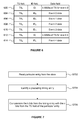
Figure 2 is a schematic diagram of a computer system including a logging unit; -
Figure 3 shows a flow chart illustrating a method of logging events in a first example; -
Figure 4 shows the format of a timestamp in the first example; -
Figure 5 shows the format of an entry for an event to be logged the logging unit; -
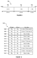
Figure 6 shows a plurality of entries stored in a log store in the first example; -
Figure 7 shows a flow chart illustrating a method of retrieving information relating to a particular event from the log store in the first example; -
Figure 8 shows the format of a timestamp in a second example; -
Figure 9 shows a flow chart illustrating a method of logging events in the second example; -
Figure 10 shows a plurality of entries stored in a log store in the second example; -
Figure 11 shows a flow chart illustrating a method of retrieving information relating to a particular event from the log store in the second example; and -
Figure 12 shows an integrated circuit manufacturing system for generating an integrated circuit embodying a processing system. - The accompanying drawings illustrate various examples. The skilled person will appreciate that the illustrated element boundaries (e.g., boxes, groups of boxes, or other shapes) in the drawings represent one example of the boundaries. It may be that in some examples, one element may be designed as multiple elements or that multiple elements may be designed as one element. Common reference numerals are used throughout the figures, where appropriate, to indicate similar features.
- Embodiments will now be described by way of example only.
- In the examples described herein, the number of bits in a timestamp that is determined for an event can be increased, thereby reducing the frequency with which the timestamp wraps. This means that the timestamps are unambiguous over a greater length of time and the time flow of the events stored in a logging unit is less frequently lost. This is achieved, whilst simultaneously decreasing the number of timestamp bits included in individual entries for respective events, and without increasing the number of bits of each entry. Therefore, every aspect of the trade-off mentioned in the background section above may be improved or at least maintained.
- This may seem counterintuitive, but it is achieved by appreciating that often a sequence of events that are logged will have similar timestamps. In particular, the most significant bits of a sequence of events which occur in quick succession will be the same as each other or very similar to each other. If the most significant bits of the timestamps of a sequence of events are the same as each other then these bits do not need to be stored repeatedly for each of the entries of the sequence of events. Instead, a least significant subsection of the bits of the timestamp (the n least significant bits of the timestamp) can be stored in the timestamp field of the entries for the events. If the n least significant bits of the timestamp have wrapped (i.e. changed from a value of 2n-1 to 0) compared to the corresponding n bits of the timestamp of the preceding entry in the trace log then an additional entry is logged which includes other bits (e.g. the most significant bits) of the timestamp. In this way, an N-bit timestamp can be determined for an event, but only the n least significant bits of the timestamp are stored in an entry for the event, where N > n.
-
Figure 2 shows a computer system including alogging unit 202 which can be used to log events in the examples described herein. Thelogging unit 202, which may be a trace logging unit, comprisescontrol logic 204 and astore 206. Thecontrol logic 204 may be implemented in hardware, software, firmware, or any combination thereof. Thestore 206 may be a memory and is configured to store entries for events, e.g. for events that have occurred in the computer system. In this example, thestore 206 is included in thelogging unit 202, whereas in other examples a store in which entries for events are logged may be external to thelogging unit 202, and may for example be implemented in Random Access Memory (RAM) in asystem memory 214. The computer system also comprises other elements which may be different in different examples, but in the example shown inFigure 2 the computer system comprises a Central Processing Unit (CPU) 208, a signal processing unit 210 (e.g. a DSP), a Graphics Processing Unit (GPU) 212, thememory 214, andother devices 216, such as a display, a camera, speakers, etc., depending on the use for which the computer system is designed. The computer system also comprises atiming clock 218 which can be used by thelogging unit 202 to determine the timestamps. It is noted that thetiming clock 218 used by thelogging unit 202 for determining the timestamps may be different (or the same in some examples) as a system clock used by the computer system to regulate the timing of the operations performed by the components of the computer system. The components of the computer system can communicate with each other via acommunications bus 220. To give some examples, the computer system may be implemented in a device such as a mobile phone, tablet, laptop, television or any other suitable device. In an example, thesignal processing unit 210 may be configured to process signals that have been received at the device or that are to be transmitted from the device (e.g. television signals, or communication signals over a suitable communication link, such as via a cellular telephone network and/or via the internet). Typically, such signal processing is performed at a very high rate, thereby creating events to be logged at a very high frequency. The other components in the computer system (e.g. theCPU 208,GPU 212,memory 214 and other devices 216) may also cause events to occur which are to be logged by thelogging unit 202. Thelogging unit 202 may maintain separate logs for events from different components, or the events from different components may all be stored in the same log. The computer system shown inFigure 2 may be an embedded system with a dedicated function, e.g. for receiving and processing broadcast signals in real-time, and as such the embedded system may include a subset of the components shown inFigure 2 (e.g. an embedded system for signal processing might not include a GPU). - Operation of the
logging unit 202 in a first example is described with reference to the flow chart shown inFigure 3 . Events occur in processing elements of the computer system shown inFigure 2 , and if those events are to be logged then, in step S302, thelogging unit 202 receives indications of the events to be logged. In particular, the indications of the events are received at thecontrol logic 204. Thelogging unit 202 may monitor the operation of the other processing elements in the computer system to detect the occurrence of events to be logged. Alternatively, or additionally, the processing elements in the computer system may send indications of events to thelogging unit 202. In both implementations, thecontrol logic 204 receives indications of events to be logged in step S302. - In step S304 the
control logic 204 determines an N-bit timestamp for the event which is to be logged. The timestamp is determined using thetiming clock 218.Figure 4 shows an example in which thetimestamp 400 includes 36 bits (i.e. N = 36). Thetimestamp 400 is made up of: (i) anupper section 402 comprising the k most significant bits, and (ii) alower section 404 comprising the n least significant bits. In the example shown inFigure 4 , k = 24 and n = 12, wherein N = k + n. The n least significant bits of the timestamp are to be included in the timestamp field of an entry for the event that is logged in thestore 206. -
Figure 5 shows the format of anentry 500 for an event which is to be stored in thestore 206. Theentry 500 comprises an n-bit timestamp field 502 and a payload. In this example, n = 12. The payload comprises anID field 504 and adata field 506. In this example, theID field 504 comprises 12 bits and the data field comprises k bits, where k = 24. TheID field 504 includes an indication of the processing element (e.g. theCPU 208 orsignal processing unit 210 or other processing element within the computer system shown inFigure 2 ) that caused the event to occur. Thedata field 506 includes data relating to the event that occurred, e.g. to indicate that an exception has occurred, or to indicate that a variable has changed its value, etc. - In step S306 the
control logic 204 determines whether there are other entries already stored in thestore 206. If the current entry will be the first entry stored in the store then the method passes to step S310, otherwise the method passes to step S308. This is because for the first entry to be included in thestore 206 there is no preceding entry, so all N bits of the timestamp are to be stored in thestore 206. - In step S308 the
control logic 204 determines whether the n leastsignificant bits 404 of thetimestamp 400 have wrapped compared to the corresponding n bits of a timestamp of a preceding entry that is stored in the store. Determining whether the lower section of the timestamp (i.e. the n least significant bits of the timestamp) has wrapped is equivalent to determining whether an upper section of the timestamp (i.e. the N - n most significant bits of the timestamp) has changed. In other words, when the n least significant bits of the timestamp have wrapped then one or more of the N - n most significant bits of the timestamp have changed. Therefore, it can be considered that in step S308, thecontrol logic 204 determines whether one or more of the N - n mostsignificant bits 402 of thetimestamp 400 are different to a corresponding one or more of the N - n most significant bits of a timestamp for a preceding event for which a preceding entry is stored in the store. If it is determined in step S308 that the n least significant bits of the timestamp have wrapped then the method passes to step S310. If it is determined in step S308 that the n least significant bits of the timestamp have not wrapped then the method passes from step S308 to step S312. - In step S310 the
control logic 204 causes a timing entry to be stored in thestore 206. The timing entry includes the set ofk bits 402 of thetimestamp 400. The k bits of thetimestamp 402 are included in the payload, e.g. in thedata field 506, of the timing entry. The n leastsignificant bits 404 of thetimestamp 400 are included in thetimestamp field 502 of the timing entry. Thecontrol logic 204 sets theID field 504 of the timing entry to a predetermined value (e.g. a value of zero) which is indicative of a timing entry. In this way, timing entries can be identified in thestore 206 by identifying entries which have the predetermined value in the ID field. Therefore, this provides a simple way to identify timing entries in thestore 206. - In step S312 the
control logic 204 causes an entry for the event to be stored in thestore 206. The n least significant bits of thetimestamp 400 are included in thetimestamp field 502 of theentry 500 for the event. Data relating to the event is included in the payload of theentry 500 for the event. That is, theID field 504 of the entry for the event includes an indication of the processing element (e.g. the signal processing unit 210) that caused the event to occur. Thedata field 506 includes data relating to the event that occurred. - It is noted that in the examples described herein, the
store 206 in which entries for events are logged is part of thelogging unit 202. However, in other examples, the store in which entries for events are logged may be external to thelogging unit 202, and may for example be part of thememory 214, and may be implemented in general purpose RAM. In these other examples, thecontrol logic 204 performs the same processes as in the examples described in detail herein to cause entries to be stored in the store (e.g. in memory 214) for events to be logged. - In some alternative examples, the
logging unit 202 could use theinternal store 206 to temporarily store the entries because it may be quicker for the logging unit to store data in thestore 206 than to send data over thebus 220 for storage in an external memory (e.g. in memory 214). The entries stored in thestore 206 can be copied to an external log store at appropriate times, e.g. periodically (i.e. at regular intervals), or when the amount of data stored in thestore 206 exceeds a threshold, or when data traffic on thebus 220 is below a threshold, to give some examples. - The method shown in
Figure 3 is performed for each of a plurality of events that occur in the computer system. If, in step S308, thecontrol logic 204 determines that the N - n most significant bits of the timestamp are the same as the corresponding N - n most significant bits of the timestamp for a preceding event for which a preceding entry is stored in the store, then a timing entry does not need to be stored (i.e. step S310 is not performed). The "preceding event" is the most recent event for which an entry is stored in thestore 206. The order in which the entries are stored in thestore 206 is preserved, so that the most recently stored entry (and therefore the most recent event) is simple to identify in thestore 206. The entry for the event includes the n least significant bits of the timestamp in the timestamp field. If the n leastsignificant bits 404 of the timestamp have not wrapped, this means that the k mostsignificant bits 402 of the timestamp are the same as the corresponding k bits of the timestamp of the preceding entry. So the k most significant bits of the timestamp do not need to be stored in thestore 206 again, i.e. a timing entry is not needed. - In order to determine, in step S308, whether the n least significant bits of the timestamp have wrapped the
control logic 204 may identify the most recently stored timing entry in thestore 206 and determine the k bits of a timestamp that are included in the payload of the timing entry. These k bits will be the same k bits of the timestamp for the most recently stored entry even if the most recently stored entry is not a timing entry. Alternatively, thelogging unit 202 may include a dedicated section of memory which is used to indicate the k bits of a timestamp of the most recently stored timing entry, whereby whenever a new timing entry is stored in thestore 206, the k bits previously stored in the dedicated section are replaced with the k bits of the timestamp for the new timing entry. In this way, the dedicated section of memory would include the k bits of the most recently stored timing entry and it is simple for thecontrol logic 204 to retrieve these k bits in step S308 to determine the k bits of the timestamp of the preceding entry. However, this would use k bits of storage space in thelogging unit 202. When thecontrol logic 204 has determined the k bits of the timestamp of the event relating to the preceding entry, these bits are compared with the k bits of the timestamp determined in step S304, and if they are the same then the n least significant bits of the determined timestamp have not wrapped, but if they are different then the n least significant bits of the determined timestamp have wrapped. -
Figure 6 shows an example of a plurality of entries (602 to 614) stored in thestore 206 for a sequence of five events (event 0 to event 4). In response to the first event (event 0) occurring, atiming entry 602 is stored in thestore 206, in step S310. The n least significant bits of the timestamp for event 0 (TS0) are stored in the timestamp field of thetiming entry 602, and the k most significant bits of the timestamp forevent 0 are stored in the data field of thetiming entry 602. The ID field of thetiming entry 602 includes a predetermined value, IDt, which indicates that theentry 602 is a timing entry. Then in step S312, anentry 604 forevent 0 is stored in thestore 206. The n least significant bits of the timestamp for event 0 (TS0) are stored in the timestamp field of theentry 604, an identifier of the source of event 0 (ID0) is stored in the ID field of theentry 604, and data relating toevent 0 is stored in the data field of theentry 604. - For the second event (event 1), the n least significant bits of the timestamp have not wrapped compared to the timestamp of
event 0. Therefore a timing entry is not stored in thestore 206 in response toevent 1 occurring. In step S312, anentry 606 forevent 1 is stored in thestore 206. The n least significant bits of the timestamp for event 1 (TS1) are stored in the timestamp field of theentry 606, an identifier of the source of event 1 (ID1) is stored in the ID field of theentry 606, and data relating toevent 1 is stored in the data field of theentry 606. - For the third event (event 2), the n least significant bits of the timestamp have not wrapped compared to the timestamp of
event 1. Therefore a timing entry is not stored in thestore 206 in response toevent 2 occurring. In step S312, anentry 608 forevent 2 is stored in thestore 206. The n least significant bits of the timestamp for event 2 (TS2) are stored in the timestamp field of theentry 608, an identifier of the source of event 2 (ID2) is stored in the ID field of theentry 608, and data relating toevent 2 is stored in the data field of theentry 608. - For the fourth event (event 3), the n least significant bits of the timestamp have not wrapped compared to the timestamp of
event 2. Therefore a timing entry is not stored in thestore 206 in response toevent 3 occurring. In step S312, anentry 610 forevent 3 is stored in thestore 206. The n least significant bits of the timestamp for event 3 (TS3) are stored in the timestamp field of theentry 610, an identifier of the source of event 3 (ID3) is stored in the ID field of theentry 610, and data relating toevent 3 is stored in the data field of theentry 610. - For the fifth event (event 4), the n least significant bits of the timestamp have wrapped compared to the timestamp of
event 3. Therefore, atiming entry 612 is stored in thestore 206, in step S310 . The n least significant bits of the timestamp for event 4 (TS4) are stored in the timestamp field of thetiming entry 612, and the k most significant bits of the timestamp forevent 4 are stored in the data field of thetiming entry 612. The ID field of thetiming entry 612 includes the predetermined value, IDt, which indicates that theentry 612 is a timing entry. Then in step S312, anentry 614 forevent 4 is stored in thestore 206. The n least significant bits of the timestamp for event 4 (TS4) are stored in the timestamp field of theentry 614, an identifier of the source of event 4 (ID4) is stored in the ID field of theentry 614, and data relating toevent 4 is stored in the data field of theentry 614. - It can be appreciated, from
Figure 6 , that the most significant k bits of the timestamps forevents store 206 because they are the same as the most significant k bits of the timestamp forevent 0 which are stored in the data field of thetiming entry 602. -
Figure 7 shows a flow chart illustrating a method of retrieving information relating to a particular event from thestore 206. In the example described below, thelogging unit 202 is used to retrieve logging data from thestore 206. In particular, in examples described below information relating toevent 2 is retrieved from thestore 206. However, as described above, in some other examples, the entries for the logged events may be stored in a log store which is external to the logging unit 202 (e.g. in RAM in memory 214). In these other examples, a unit other than thelogging unit 202 may be used to retrieve logging data from the log store, but the principles of the retrieval of the logging data are the same as in the example described below in which it is thelogging unit 202 that retrieves the logging data from thestore 206. - In step S702 the
control logic 204 reads the particular entry for the particular event (e.g. entry 608 for event 2) from thestore 206. As described above, data relating toevent 2 is included in the payload ofentry 608. Also as described above, the n least significant bits of the timestamp for event 2 (TS2) are stored in the timestamp field of theentry 608, so by readingentry 608, these n bits of the timestamp for the event can be determined. However, as described above, the full timestamp forevent 2 comprises N bits, where N > n, so there are some bits of the timestamp forevent 2 which are not included in theentry 608. - In step S704 the control logic identifies a timing entry preceding the particular entry in the store. This can be done by identifying an entry in the
store 206 which has the predetermined value (IDt) in its ID field. The identified timing entry is the timing entry most recently stored in thestore 206 prior to the particular entry. So in this example, whereentry 608 is the entry of the event for which information is being retrieved, thetiming entry 602 is identified as being the timing entry most recently stored in thestore 206 prior to theentry 608. Thetiming entry 602 has the k most significant bits of the timestamp in its data field. - In step S706 the control logic concatenates the k bits of the timestamp from the identified
timing entry 602 with the n bits of the timestamp from the timestamp field of theentry 608 to thereby construct the timestamp forevent 2. In this example, k = N - n such that the result of concatenating the k bits and the n bits is the N-bit timestamp for the event. In this way the N-bit timestamp forevent 2 is determined even though only n of the bits of the timestamp are included in theentry 608 forevent 2. - In the examples described above, the N-bit timestamp is divided into just two sections: the most
significant k bits 402 and the leastsignificant n bits 404, as shown inFigure 4 , such that k = N - n. The k bits can be included in the data field of a timing entry. However, in other examples, the N-bit timestamp may be divided into more than two sections. In general, the timestamp may be an arbitrary length and it may be divided into an arbitrary number of sections.Figure 8 shows an example of atimestamp 800 which comprises 56 bits (i.e. N = 56), and which is divided into three sections: the mostsignificant m bits 802, the next mostsignificant k bits 804, and the leastsignificant n bits 806. Therefore, in this example k < N - n. In particular, in this example, N = m + k + n. - Similarly to in the examples given above in relation to
Figures 3 to 7 , the k bits of the timestamp are more significant bits of the timestamp than the n least significant bits of the timestamp. In particular, the k bits of the timestamp are the k next least significant bits of the timestamp other than the n least significant bits of the timestamp. However, in the examples described with reference toFigures 8 to 11 the timestamp includes afurther m bits 802 which are more significant than the kbits 804 of thetimestamp 800. In the example shown inFigure 8 , thetimestamp 800 is divided into three sections because it includes too many bits to put all of the bits of the timestamp except the n least significant bits into the data field of a timing entry. - Operation of the
logging unit 202 in a second example is described with reference to the flow chart shown inFigure 9 . Events occur in processing elements of the computer system shown inFigure 2 , and if those events are to be logged then in step S902, thecontrol logic 204 of thelogging unit 202 receives indications of the events to be logged, as described above in relation to step S302. - In step S904 the
control logic 204 determines an N-bit timestamp for the event which is to be logged. The timestamp is determined using thetiming clock 218. In this example, the timestamp includes 56 bits as shown inFigure 8 . The n leastsignificant bits 806 of thetimestamp 800 are to be included in the timestamp field of an entry for the event that is logged in thestore 206. - The format of the entries that are stored in the
store 206 is the same as in the examples described above, and shown inFigure 5 . Therefore, an entry comprises an n-bit timestamp field 502 and a payload which includes an ID field and a data field, e.g. where n = 12 and where the ID field comprises 12 bits and the data field comprises k bits, where k = 24. In this example, there are two types of timing entry: (i) a first-level timing entry which includes k bits of a timestamp in its payload, and (ii) a second-level timing entry which includes m bits of a timestamp in its payload. - In step S906 the
control logic 204 determines whether there are other entries already stored in thestore 206. If the current entry will be the first entry stored in the store then the method passes to step S912, otherwise the method passes to step S908. This is because for the first entry to be included in thestore 206 there is no preceding entry, so all N bits of the timestamp are to be stored in thestore 206. - In step S908 the
control logic 204 determines whether the n leastsignificant bits 806 of thetimestamp 800 have wrapped compared to the corresponding n bits of a timestamp of a preceding entry that is stored in the store. As described above, determining whether the lower section of the timestamp (i.e. the n least significant bits of the timestamp) has wrapped is equivalent to determining whether an upper section of the timestamp (i.e. the N - n most significant bits of the timestamp) has changed. Therefore, it can be considered that in step S908, thecontrol logic 204 determines whether one or more of the N - n most significant bits (802 and 804) of thetimestamp 800 are different to a corresponding one or more of the N - n most significant bits of a timestamp for a preceding event for which a preceding entry is stored in the store. If it is determined in step S908 that the n least significant bits of the timestamp have wrapped then the method passes to step S910. If it is determined in step S908 that the n least significant bits of the timestamp have not wrapped then the method passes from step S908 to step S916. The determination as to whether the n least significant bits of the timestamp have wrapped can be performed as described above, e.g. by determining the k bits of the timestamp of an event relating to the preceding entry in the store (e.g. by identifying the preceding first-level timing entry in thestore 206, or retrieving this from a dedicated section of memory of the logging unit 202). - In step S910 the
control logic 204 determines whether thek bits 804 of thetimestamp 800 have wrapped compared to the corresponding k bits of a timestamp of an event for which a preceding entry is stored in thestore 206. Determining whether the k bits of the timestamp have wrapped is equivalent to determining whether the N - k - n most significant bits of the timestamp have changed. Therefore, it can be considered that in step S910, thecontrol logic 204 determines whether one or more of the N - k - n mostsignificant bits 802 of thetimestamp 800 are different to a corresponding one or more of the N - k - n most significant bits of a timestamp for a preceding event for which a preceding entry is stored in the store. - In order to determine, in step S910, whether the k bits of the timestamp have wrapped the
control logic 204 may identify the most recently stored second-level timing entry in thestore 206 and determine the m bits of a timestamp that are included in the payload of the second-level timing entry. These m bits will be the same m bits of the timestamp for the most recently stored entry even if the most recently stored entry is not a second-level timing entry. Alternatively, thelogging unit 202 may include a dedicated section of memory which is used to indicate the m bits of a timestamp of the most recently stored second-level timing entry, whereby whenever a new second-level timing entry is stored in thestore 206, the m bits previously stored in the dedicated section of memory are replaced with the m bits of the timestamp for the new second-level timing entry. In this way the dedicated section of memory would include the m bits of the most recently stored second-level timing entry and it is simple for thecontrol logic 204 to retrieve these m bits in step S910 to determine the m bits of the timestamp of the preceding entry. However, this would use m bits of storage space in thelogging unit 202. When thecontrol logic 204 has determined the m bits of the timestamp of the event relating to the preceding entry, these bits are compared with the m bits of the timestamp determined in step S904, and if they are the same then the k bits of the determined timestamp have not wrapped, but if they are different then the k bits of the determined timestamp have wrapped. - If it is determined in step S910 that the k bits of the timestamp have wrapped then the method passes to step S912. If it is determined in step S910 that the k bits of the timestamp have not wrapped then the method passes from step S910 to step S914.
- In step S912 the
control logic 204 causes a second-level timing entry to be stored in thestore 206. The second-level timing entry includes the set of mbits 802 of thetimestamp 800. The mbits 802 of thetimestamp 800 are included in the payload, e.g. in thedata field 506, of the second-level timing entry. The n leastsignificant bits 806 of thetimestamp 800 are included in thetimestamp field 502 of the second-level timing entry. Thecontrol logic 204 sets theID field 504 of the second-level timing entry to a second predetermined value (e.g. a value of one) which is indicative of a second-level timing entry. In this way, second-level timing entries can be identified in thestore 206 by identifying entries which have the second predetermined value in the ID field. Therefore, this provides a simple way to identify second-level timing entries in thestore 206. - In step S914 the
control logic 204 causes a first-level timing entry to be stored in thestore 206. The first-level timing entry includes the set ofk bits 804 of thetimestamp 800. Thek bits 804 of thetimestamp 800 are included in the payload, e.g. in thedata field 506, of the first-level timing entry. The n leastsignificant bits 806 of thetimestamp 800 are included in thetimestamp field 502 of the first-level timing entry. Thecontrol logic 204 sets theID field 504 of the first-level timing entry to a first predetermined value (e.g. a value of zero) which is indicative of a first-level timing entry. In this way, first-level timing entries can be identified in thestore 206 by identifying entries which have the first predetermined value in the ID field. Therefore, this provides a simple way to identify first-level timing entries in thestore 206. - In step S916 the
control logic 204 causes an entry for the event to be stored in thestore 206. The n leastsignificant bits 806 of thetimestamp 800 are included in thetimestamp field 502 of theentry 500 for the event. Data relating to the event is included in the payload of theentry 500 for the event. That is, theID field 504 of the entry for the event includes an indication of the processing element (e.g. the signal processing unit 210) that caused the event to occur. Thedata field 506 includes data relating to the event that occurred. - The method shown in
Figure 9 is performed for each of a plurality of events that occur in the computer system. If, in step S908, thecontrol logic 204 determines that the n least significant bits of the timestamp have not wrapped compared to the corresponding n bits of the timestamp of a preceding entry that is stored in the store, then a timing entry does not need to be stored (i.e. steps S910, S912 and S914 are not performed). The "preceding entry" is the entry most recently stored in thestore 206. The order in which the entries are stored in thestore 206 is preserved, so that the most recently stored entry is simple to identify in thestore 206. If the n leastsignificant bits 404 of the timestamp have not wrapped, this means that the (m + k) mostsignificant bits store 206 again, i.e. a timing entry is not needed. -
Figure 10 shows an example of a plurality of entries (1002 to 1022) stored in thestore 206 for a sequence of six events (event 0 to event 5). In response to the first event (event 0) occurring, a second-level timing entry 1002 is stored in thestore 206, in step S912. The n least significant bits of the timestamp for event 0 (TS0) are stored in the timestamp field of the second-level timing entry 1002, and the m most significant bits of the timestamp forevent 0 are stored in the data field of the second-level timing entry 1002. The ID field of the second-level timing entry 1002 includes a predetermined value, IDt2, which indicates that theentry 1002 is a second-level timing entry. Then in step S914, a first-level timing entry 1004 is stored in thestore 206. The n least significant bits of the timestamp for event 0 (TS0) are stored in the timestamp field of the first-level timing entry 1004, and the k bits of the timestamp forevent 0 are stored in the data field of the first-level timing entry 1004. The ID field of the first-level timing entry 1004 includes a predetermined value, IDt1, which indicates that theentry 1004 is a first-level timing entry. Then in step S916, anentry 1006 forevent 0 is stored in thestore 206. The n least significant bits of the timestamp for event 0 (TS0) are stored in the timestamp field of theentry 1006, an identifier of the source of event 0 (ID0) is stored in the ID field of theentry 1006, and data relating toevent 0 is stored in the data field of theentry 1006. - For the second and third events (
event 1 and event 2), the n least significant bits of their timestamps have not wrapped compared to the timestamp ofevent 0. Therefore a timing entry is not stored in thestore 206 in response to these events occurring. Instead, anentry 1008 forevent 1 is stored in thestore 206. The n least significant bits of the timestamp for event 1 (TS1) are stored in the timestamp field of theentry 1008, an identifier of the source of event 1 (ID1) is stored in the ID field of theentry 1008, and data relating toevent 1 is stored in the data field of theentry 1008. Anentry 1010 forevent 2 is stored in thestore 206. The n least significant bits of the timestamp for event 2 (TS2) are stored in the timestamp field of theentry 1010, an identifier of the source of event 2 (ID2) is stored in the ID field of theentry 1010, and data relating toevent 2 is stored in the data field of theentry 1010. - For the fourth event (event 3), the n least significant bits of the timestamp have wrapped compared to the timestamp of
event 2, but the k bits of the timestamp have not wrapped compared to the timestamp ofevent 2. Therefore, a first-level timing entry 1012 is stored in thestore 206, in step S914. The n least significant bits of the timestamp for event 3 (TS3) are stored in the timestamp field of thetiming entry 1012, and the k bits of the timestamp forevent 3 are stored in the data field of the first-level timing entry 1012. The ID field of the first-level timing entry 1012 includes the predetermined value, IDt1, which indicates that theentry 1012 is a first-level timing entry. Then in step S916, anentry 1014 forevent 3 is stored in thestore 206. The n least significant bits of the timestamp for event 3 (TS3) are stored in the timestamp field of theentry 1014, an identifier of the source of event 3 (ID3) is stored in the ID field of theentry 1014, and data relating toevent 3 is stored in the data field of theentry 1014. - For the fifth event (event 4), the n least significant bits of the timestamp have not wrapped compared to the timestamp of
event 3. Therefore a timing entry is not stored in thestore 206 in response toevent 4 occurring. In step S916, anentry 1016 forevent 4 is stored in thestore 206. The n least significant bits of the timestamp for event 4 (TS4) are stored in the timestamp field of theentry 1016, an identifier of the source of event 4 (ID4) is stored in the ID field of theentry 1016, and data relating toevent 4 is stored in the data field of theentry 1016. - For the sixth event (event 5), the n least significant bits of the timestamp and the k bits of the timestamp have wrapped compared to the timestamp of
event 4. Therefore, a second-level timing entry 1018 is stored in thestore 206, in step S912. The n least significant bits of the timestamp for event 5 (TS5) are stored in the timestamp field of the second-level timing entry 1018, and the m most significant bits of the timestamp forevent 5 are stored in the data field of the second-level timing entry 1018. The ID field of the second-level timing entry 1018 includes the predetermined value, IDt2, which indicates that theentry 1018 is a second-level timing entry. Then in step S914, a first-level timing entry 1020 is stored in thestore 206. The n least significant bits of the timestamp for event 5 (TS5) are stored in the timestamp field of the first-level timing entry 1020, and the k bits of the timestamp forevent 5 are stored in the data field of the first-level timing entry 1020. The ID field of the first-level timing entry 1020 includes the predetermined value, IDt1, which indicates that theentry 1020 is a first-level timing entry. Then in step S916, anentry 1022 forevent 5 is stored in thestore 206. The n least significant bits of the timestamp for event 5 (TS5) are stored in the timestamp field of theentry 1022, an identifier of the source of event 5 (ID5) is stored in the ID field of theentry 1022, and data relating toevent 5 is stored in the data field of theentry 1022. - It can be appreciated, from
Figure 10 , that the m most significant bits of the timestamps forevents store 206 because they are the same as the most significant m bits of the timestamp forevent 0 which are stored in the data field of the second-level timing entry 1002. Furthermore, the k bits of the timestamps forevents store 206 because they are the same as either the k bits of the timestamp forevent 0 which are stored in the data field of the first-level timing entry 1004 or the k bits of the timestamp forevent 3 which are stored in the data field of the first-level timing entry 1012. -
Figure 11 shows a flow chart illustrating a method of retrieving information relating to a particular event from thelogging unit 202 when the timestamps are divided into three sections as described above in relation toFigures 8 to 10 . In the example described below, thelogging unit 202 is used to retrieve logging data from thestore 206. In particular, in examples described below information relating toevent 3 is retrieved from thestore 206. However, as described above, in some other examples, the entries for the logged events may be stored in a log store which is external to the logging unit 202 (e.g. in RAM in memory 214). In these other examples, a unit other than thelogging unit 202 may be used to retrieve logging data from the log store, but the principles of the retrieval of the logging data are the same as in the example described below in which it is thelogging unit 202 that retrieves the logging data from thestore 206. - In step S1102 the
control logic 204 reads the particular entry for the particular event (e.g. entry 1014 for event 3) from thestore 206. As described above, data relating toevent 3 is included in the payload ofentry 1014. Also as described above, the n least significant bits of the timestamp for event 3 (TS3) are stored in the timestamp field of theentry 1014, so by readingentry 1014, these n bits of the timestamp for the event can be determined. However, as described above, the full timestamp forevent 3 comprises N bits, where N > n, so there are some bits of the timestamp forevent 3 which are not included in theentry 1014. - In step S1104 the control logic identifies a first-level timing entry preceding the particular entry in the store. This can be done by identifying an entry in the
store 206 which has the predetermined value (IDt1) in its ID field. The identified first-level timing entry is the first-level timing entry most recently stored in thestore 206 prior to the particular entry. So in this example, whereentry 1014 is the entry of the event for which information is being retrieved, the first-level timing entry 1012 is identified as being the first-level timing entry most recently stored in thestore 206 prior to theentry 1014. The first-level timing entry 1012 has the k bits of the timestamp in its data field. - In step S1106 the control logic identifies a second-level timing entry preceding the particular entry in the store. This can be done by identifying an entry in the
store 206 which has the predetermined value (IDt2) in its ID field. The identified second-level timing entry is the second-level timing entry most recently stored in thestore 206 prior to the particular entry. So in this example, whereentry 1014 is the entry of the event for which information is being retrieved, the second-level timing entry 1002 is identified as being the second-level timing entry most recently stored in thestore 206 prior to theentry 1014. The second-level timing entry 1002 has the m most significant bits of the timestamp in its data field. - In step S1108 the control logic concatenates the m bits of the timestamp from the identified second-
level timing entry 1002 with the k bits of the timestamp from the identified first-level timing entry 1012 and the n bits of the timestamp from the timestamp field of theentry 1014 to thereby construct the timestamp forevent 3. In this example, N = m + k + n such that the result of concatenating the m bits, the k bits and the n bits is the N-bit timestamp for the event. In this way the N-bit timestamp forevent 3 is determined even though only n of the bits of the timestamp are included in theentry 1014 forevent 3. - In accordance with the examples described above, the number of bits (N) included in a timestamp can be increased, such that the timestamp wraps less frequently, meaning that the time flow of the logged events is lost less frequently. This is achieved whilst also reducing the number of bits (n) that are included in the timestamp field of each of the entries, such that more bits of an entry can be used for the payload. The way this is achieved is by including additional timing entries when the n least significant bits of the timestamp have wrapped. There is a trade-off between the total timestamp wrap time

store 206. - The examples described herein are particularly useful for trace logging where memory space for logging purposes may be particularly limited, e.g. compared to logging performed in logic analysers. The values of n, k, m and N can be set according to the conditions in which the logging unit is to be used (e.g. the expected frequency with which events occur), and also based on the frequency of the
timing clock 218. Alternatively, the frequency of thetiming clock 218 may be set based on one or more of: (i) an expected frequency of events, (ii) the value of n, and (iii) the value of N. Increasing the frequency of thetiming clock 218 will increase the resolution of the timestamps thereby providing a greater accuracy for the relative timings of events stored in thestore 206. However, increasing the frequency of thetiming clock 218 will also decrease the time over which the timestamp will wrap. For example, with an N-bit timestamp and a timing clock frequency of f, the timestamp of an event at time t will be the same as the timestamp of an event at time

timing clock 218, f, is set based on the expected frequency of the events. For example, if the computer system is for signal processing in a WiFi transceiver, then events, which might include events indicating the arrival of packet headers and data payloads, are likely to occur quickly so the frequency of thetiming clock 218 can be set to be high (e.g. at 350MHz) to distinguish between the timings of different events. In a contrary example, if the computer system is for use in an e-reader, then events are likely to occur at a lower frequency, so the frequency of thetiming clock 218 can be set to be lower (e.g. at 10MHz) to avoid the timestamp becoming ambiguous in the time between events. As mentioned above, thetiming clock 218 which is used by thelogging unit 202 might not be used to regulate the timing of other components in the computer system, so setting the frequency of thetiming clock 218 might not affect the clocks used by the other components of the computer system. - As described in the background section above, if the frequency of the timing clock is 350MHz, an 18-bit timestamp will wrap every

Figure 4 ) will wrap every

Figure 8 ) will wrap approximately every
- Any of the specific numbers given in the examples described above could be changed to other suitable values as would be apparent to a person skilled in the art. For example, in the examples described above each entry includes 48 bits, but in other examples the entries could include a different number of bits. Furthermore, in the examples described above, the payload of an entry includes an ID field and a data field. In other examples, the payload may include additional or alternative fields and the sizes of the fields may be different to those described above. Furthermore, in general, n ≥ 1 and k ≥ 1.
- The embodiments described above, in which the timestamps are divided into two or three sections, are given by way of example only. More generally, as mentioned above, the timestamps may be divided into any number of sections or "levels". It would be apparent to a person skilled in the art how to implement the methods described herein with timestamps divided into more than three sections.
- In the examples described above a timing entry includes, in its timestamp field, the n least significant bits of the timestamp for an event. For example, the
timing entry 612 shown inFigure 6 includes the n least significant bits (TS4) of the timestamp forevent 4 in its timestamp field. However, it is noted that there is duplication of the storage of the n least significant bits of a timestamp when a timing entry is stored. This can be seen inFigure 6 in that when a timing entry is stored (e.g. timingentries 602 and 612), the bits in the timestamp field of the timing entry are the same as the bits in the timestamp field of the next entry in the store (e.g. entries 604 and 614). Therefore, in other examples, the timestamp field of a timing entry might include bits other than the n least significant bits of the timestamp. In this way, more timestamp bits can be included in a timing entry. For example, the value of k may be greater than the number of bits that can be included in the data field of an entry. For example, by comparison toFigures 4 and 5 , a 48-bit timestamp could be used, where n = 12 and k = 36, and still only one level of timing entry may be used because a timing entry could include 36 bits of a timestamp. This can be done by including 24 bits of a timestamp in thedata field 506 and a further 12 bits of the timestamp in thetimestamp field 502 of a timing entry. In this way, the k bits of the timestamp are distributed over the data and timestamp fields of the timing entry. This does not cause a problem because the n least significant bits of the timestamp are included in the timestamp field of the next entry (e.g. inentries Figure 6 ). In this way, the duplication of the storage of the n least significant bits of a timestamp is removed. For example, this would allow a 48-bit timestamp to be used (rather than a 36 bit timestamp as in the examples described above) at no extra cost in terms of needing to store extra timing entries. More generally, some bits of the set of k bits of the timestamp may be included in the payload of the timing entry, and other bits of the set of k bits of the timestamp may be included in the timestamp field of the timing entry. - Generally, any of the functions, methods, techniques or components described above (e.g. the logging unit 202) can be implemented in modules using software, firmware, hardware (e.g., fixed logic circuitry), or any combination of these implementations. The terms "module," "functionality," "component", "block", "unit" and "logic" are used herein to generally represent software, firmware, hardware, or any combination thereof.
- In the case of a software implementation of the
control logic 204, the control logic represents program code that performs specified tasks when executed on a processor. In one example, the control logic described may be performed by a computer configured with software in machine readable form stored on a computer-readable medium. One such configuration of a computer-readable medium is signal bearing medium and thus is configured to transmit the instructions (e.g. as a carrier wave) to the computing device, such as via a network. The computer-readable medium may also be configured as a non-transitory computer-readable storage medium and thus is not a signal bearing medium. Examples of a computer-readable storage medium include a random-access memory (RAM), read-only memory (ROM), an optical disc, flash memory, hard disk memory, and other memory devices that may use magnetic, optical, and other techniques to store instructions or other data and that can be accessed by a machine. - The software may be in the form of a computer program comprising computer program code for configuring a computer to perform the constituent portions of described methods or in the form of a computer program comprising computer program code means adapted to perform all the steps of any of the methods described herein when the program is run on a computer and where the computer program may be embodied on a computer readable medium. The program code can be stored in one or more computer readable media. The features of the techniques described herein are platform-independent, meaning that the techniques may be implemented on a variety of computing platforms having a variety of processors.
- Those skilled in the art will also realize that all, or a portion of the functionality, techniques or methods described herein may be carried out by a dedicated circuit, an application-specific integrated circuit, a programmable logic array, a field-programmable gate array, or the like. For example, the module, functionality, component, unit or logic (e.g. the
logging unit 202 and its components) may comprise hardware in the form of circuitry. Such circuitry may include transistors and/or other hardware elements available in a manufacturing process. Such transistors and/or other elements may be used to form circuitry or structures that implement and/or contain memory, such as registers, flip flops, or latches, logical operators, such as Boolean operations, mathematical operators, such as adders, multipliers, or shifters, and interconnects, by way of example. Such elements may be provided as custom circuits or standard cell libraries, macros, or at other levels of abstraction. Such elements may be interconnected in a specific arrangement. The module, functionality, component, unit or logic (e.g. the components of the logging unit 202) may include circuitry that is fixed function and circuitry that can be programmed to perform a function or functions; such programming may be provided from a firmware or software update or control mechanism. In an example, hardware logic has circuitry that implements a fixed function operation, state machine or process. - It is also intended to encompass software which "describes" or defines the configuration of hardware that implements a module, functionality, component, unit or logic (e.g. the components of the logging unit 202) described above, such as HDL (hardware description language) software, as is used for designing integrated circuits, or for configuring programmable chips, to carry out desired functions. That is, there may be provided a computer readable storage medium having encoded thereon computer readable program code in the form of an integrated circuit definition dataset that when processed in an integrated circuit manufacturing system configures the system to manufacture a logging unit configured to perform any of the methods described herein, or to manufacture a logging unit comprising any apparatus described herein. The IC definition dataset may be in the form of computer code, e.g. written in a suitable HDL such as register-transfer level (RTL) code. An example of processing an integrated circuit definition dataset at an integrated circuit manufacturing system so as to configure the system to manufacture a logging unit will now be described with respect to
Figure 12 . -
Figure 12 shows an example of an integrated circuit (IC)manufacturing system 1202 which comprises alayout processing system 1204 and an integratedcircuit generation system 1206. TheIC manufacturing system 1202 is configured to receive an IC definition dataset (e.g. defining a logging unit as described in any of the examples herein), process the IC definition dataset, and generate an IC according to the IC definition dataset (e.g. which embodies a logging unit as described in any of the examples herein). The processing of the IC definition dataset configures theIC manufacturing system 1202 to manufacture an integrated circuit embodying a logging unit as described in any of the examples herein. More specifically, thelayout processing system 1204 is configured to receive and process the IC definition dataset to determine a circuit layout. Methods of determining a circuit layout from an IC definition dataset are known in the art, and for example may involve synthesising RTL code to determine a gate level representation of a circuit to be generated, e.g. in terms of logical components (e.g. NAND, NOR, AND, OR, MUX and FLIP-FLOP components). A circuit layout can be determined from the gate level representation of the circuit by determining positional information for the logical components. This may be done automatically or with user involvement in order to optimise the circuit layout. When thelayout processing system 1204 has determined the circuit layout it may output a circuit layout definition to theIC generation system 1206. TheIC generation system 1206 generates an IC according to the circuit layout definition, as is known in the art. For example, theIC generation system 1206 may implement a semiconductor device fabrication process to generate the IC, which may involve a multiple-step sequence of photo lithographic and chemical processing steps during which electronic circuits are gradually created on a wafer made of semiconducting material. The circuit layout definition may be in the form of a mask which can be used in a lithographic process for generating an IC according to the circuit definition. Alternatively, the circuit layout definition provided to theIC generation system 1206 may be in the form of computer-readable code which theIC generation system 1206 can use to form a suitable mask for use in generating an IC. The different processes performed by theIC manufacturing system 1202 may be implemented all in one location, e.g. by one party. Alternatively, theIC manufacturing system 1202 may be a distributed system such that some of the processes may be performed at different locations, and may be performed by different parties. For example, some of the stages of: (i) synthesising RTL code representing the IC definition dataset to form a gate level representation of a circuit to be generated, (ii) generating a circuit layout based on the gate level representation, (iii) forming a mask in accordance with the circuit layout, and (iv) fabricating an integrated circuit using the mask, may be performed in different locations and/or by different parties. - In other examples, processing of the integrated circuit definition dataset at an integrated circuit manufacturing system may configure the system to manufacture a logging unit without the IC definition dataset being processed so as to determine a circuit layout. For instance, an integrated circuit definition dataset may define the configuration of a reconfigurable processor, such as an FPGA, and the processing of that dataset may configure an IC manufacturing system to generate a reconfigurable processor having that defined configuration (e.g. by loading configuration data to the FPGA).
- In some examples, an integrated circuit definition dataset could include software which runs on hardware defined by the dataset or in combination with hardware defined by the dataset. In the example shown in
Figure 12 , the IC generation system may further be configured by an integrated circuit definition dataset to, on manufacturing an integrated circuit, load firmware onto that integrated circuit in accordance with program code defined at the integrated circuit definition dataset or otherwise provide program code with the integrated circuit for use with the integrated circuit.
The term 'processor' and 'computer' are used herein to refer to any device, or portion thereof, with processing capability such that it can execute instructions, or a dedicated circuit capable of carrying out all or a portion of the functionality or methods, or any combination thereof. - Although the subject matter has been described in language specific to structural features and/or methodological acts, it is to be understood that the subject matter defined in the appended claims is not necessarily limited to the specific features or acts described above. Rather, the specific features and acts described above are disclosed as example forms of implementing the claims. It will be understood that the benefits and advantages described above may relate to one example or may relate to several examples.
- Any range or value given herein may be extended or altered without losing the effect sought, as will be apparent to the skilled person. The steps of the methods described herein may be carried out in any suitable order, or simultaneously where appropriate. Aspects of any of the examples described above may be combined with aspects of any of the other examples described to form further examples without losing the effect sought.
Claims (15)
- A logging unit for logging events by causing entries to be stored in a store, wherein each of said entries comprises an n-bit timestamp field and a payload, the logging unit comprising control logic configured to:determine a timestamp for an event which is to be logged, wherein the determined timestamp comprises N bits, where N > n;cause a timing entry which includes a set of k bits of the determined timestamp to be stored in the store if one or more of the N - n most significant bits of the determined timestamp are different to a corresponding one or more of the N - n most significant bits of a timestamp for a preceding event for which a preceding entry is stored in the store, said k bits being more significant bits of the determined timestamp than the n least significant bits of the determined timestamp; andcause an entry for the event to be stored in the store, wherein the n least significant bits of the determined timestamp are included in the timestamp field of the entry for the event.
- The logging unit of claim 1 wherein said k bits are the k next least significant bits of the determined timestamp other than the n least significant bits of the determined timestamp.
- The logging unit of claim 1 or 2 wherein the control logic is configured to cause the set of k bits of the determined timestamp to be included in the payload of the timing entry.
- The logging unit of any preceding claim wherein the control logic is configured to cause the n least significant bits of the determined timestamp to be included in the timestamp field of the timing entry.
- The logging unit of claim 1 or 2 wherein the control logic is configured to:cause some bits of the set of k bits of the determined timestamp to be included in the payload of the timing entry, andcause other bits of the set of k bits of the determined timestamp to be included in the timestamp field of the timing entry.
- The logging unit of any preceding claim wherein said preceding event is the most recent event for which an entry is stored in the store.
- The logging unit of any preceding claim wherein the payload of an entry includes: (i) an ID field, and (ii) a data field,
and wherein the control logic is configured to set the ID field of the timing entry to a predetermined value which is indicative of a timing entry. - The logging unit of any preceding claim wherein the control logic is configured to determine the timestamp for the event which is to be logged using a timing clock, and wherein the frequency of the timing clock is set based on one or more of: (i) an expected frequency of events, (ii) the value of n, and (iii) the value of N.
- The logging unit of any preceding claim wherein k = N - n, wherein the k bits are the most significant bits of the determined timestamp.
- The logging unit of any of claims 1 to 8 wherein k < N - n, wherein said timing entry including the set of k bits of the determined timestamp is a first-level timing entry, and wherein the control logic is further configured to cause a second-level timing entry which includes a set of m bits of the determined timestamp to be stored in the store if one or more of the N - k - n most significant bits of the determined timestamp are different to a corresponding one or more of the N - k - n most significant bits of the timestamp for the preceding event for which the preceding entry is stored in the store, said m bits being more significant bits of the determined timestamp than the k bits of the determined timestamp.
- The logging unit of any preceding claim wherein the control logic is further configured to:read a particular entry for a particular event from the store; andconstruct the timestamp for the particular event by: (i) identifying a timing entry preceding the particular entry in the store, and (ii) concatenating the k bits of the timestamp from the identified timing entry with the n bits of the timestamp from the timestamp field of the particular entry.
- A method of logging events by storing entries in a store, each of said entries comprising an n-bit timestamp field and a payload, the method comprising:determining a timestamp for an event which is to be logged, wherein the determined timestamp comprises N bits, where N > n;if one or more of the N - n most significant bits of the determined timestamp are different to a corresponding one or more of the N - n most significant bits of a timestamp for a preceding event for which a preceding entry is stored in the store, storing a timing entry in the store, said timing entry including a set of k bits of the determined timestamp, said k bits being more significant bits of the determined timestamp than the n least significant bits of the determined timestamp; andstoring an entry for the event in the store, wherein the n least significant bits of the determined timestamp are included in the timestamp field of the entry for the event.
- A method of retrieving information relating to a particular event from a store configured to store entries, each of said entries comprising an n-bit timestamp field and a payload, and wherein the particular event is associated with a timestamp comprising N bits, where N > n, the method comprising:reading a particular entry for the particular event from the store, wherein the n least significant bits of the timestamp are included in the timestamp field of the particular entry;identifying a timing entry preceding the particular entry in the store, wherein the identified timing entry includes a set of k bits of the timestamp for the particular entry, said k bits being more significant bits of the timestamp than the n least significant bits of the timestamp; andconcatenating the k bits of the timestamp from the identified timing entry with the n bits of the timestamp from the timestamp field of the particular entry, for use in constructing the timestamp for the particular event.
- A computer readable storage medium having encoded thereon computer readable code adapted to perform the steps of the method of claim 12 or 13 when the code is run on a computer.
- A computer readable storage medium having stored thereon a computer readable description of an integrated circuit that, when processed in an integrated circuit manufacturing system, causes the integrated circuit manufacturing system to manufacture a logging unit as claimed in any of claims 1 to 11.
Applications Claiming Priority (1)
| Application Number | Priority Date | Filing Date | Title |
|---|---|---|---|
| GB1504975.2A GB2536655B (en) | 2015-03-24 | 2015-03-24 | Logging events with timestamps |
Publications (2)
| Publication Number | Publication Date |
|---|---|
| EP3098733A1 true EP3098733A1 (en) | 2016-11-30 |
| EP3098733B1 EP3098733B1 (en) | 2020-01-15 |
Family
ID=53052323
Family Applications (1)
| Application Number | Title | Priority Date | Filing Date |
|---|---|---|---|
| EP16160332.9A Active EP3098733B1 (en) | 2015-03-24 | 2016-03-15 | Logging events with timestamps |
Country Status (4)
| Country | Link |
|---|---|
| US (1) | US10255161B2 (en) |
| EP (1) | EP3098733B1 (en) |
| CN (1) | CN106021058B (en) |
| GB (1) | GB2536655B (en) |
Families Citing this family (7)
| Publication number | Priority date | Publication date | Assignee | Title |
|---|---|---|---|---|
| GB2497154B (en) * | 2012-08-30 | 2013-10-16 | Imagination Tech Ltd | Tile based interleaving and de-interleaving for digital signal processing |
| GB2518921B (en) * | 2014-03-24 | 2016-02-17 | Imagination Tech Ltd | High definition timing synchronisation function |
| WO2016154841A1 (en) * | 2015-03-30 | 2016-10-06 | Telefonaktiebolaget Lm Ericsson (Publ) | Load balancing |
| US10637920B2 (en) * | 2017-08-18 | 2020-04-28 | Digital 14 Llc | System, method, and computer program product for peer-to-peer event ordering using a two part event identifier |
| US10764855B1 (en) * | 2018-02-26 | 2020-09-01 | Marvell Asia Pte, Ltd. | Synchronizing clocks in a wireless network |
| US11082544B2 (en) | 2018-03-09 | 2021-08-03 | Microchip Technology Incorporated | Compact timestamp, encoders and decoders that implement the same, and related devices, systems and methods |
| US11093364B2 (en) * | 2018-12-18 | 2021-08-17 | Micron Technology, Inc. | Management of event log information of a memory sub-system |
Citations (1)
| Publication number | Priority date | Publication date | Assignee | Title |
|---|---|---|---|---|
| US20150082325A1 (en) * | 2013-09-15 | 2015-03-19 | Sandisk Technologies Inc. | Apparatuses and methods for generating and tracing event codes |
Family Cites Families (6)
| Publication number | Priority date | Publication date | Assignee | Title |
|---|---|---|---|---|
| US7031869B2 (en) * | 2001-12-28 | 2006-04-18 | Hewlett-Packard Development Company, L.P. | Method and apparatus for managing timestamps when storing data |
| WO2008043082A2 (en) * | 2006-10-05 | 2008-04-10 | Splunk Inc. | Time series search engine |
| US20090271434A1 (en) * | 2008-04-29 | 2009-10-29 | George H Allan | Method and System for Storing Trace Data |
| US8924767B2 (en) * | 2009-12-17 | 2014-12-30 | Texas Instruments Incorporated | Minimizing the use of chip routing resources when using timestamped instrumentation data by transmitting the most significant bits of the timestamp in series and transmitting the least significant bits of the timestamp in parallel |
| US9190906B2 (en) * | 2012-05-16 | 2015-11-17 | Intel Deutschland Gmbh | Digital event generator, comparator, switched mode energy converter and method |
| CN102929936B (en) * | 2012-09-26 | 2016-08-24 | 东软集团股份有限公司 | Log recording method, log inquiring method and system |
-
2015
- 2015-03-24 GB GB1504975.2A patent/GB2536655B/en active Active
-
2016
- 2016-03-15 EP EP16160332.9A patent/EP3098733B1/en active Active
- 2016-03-23 CN CN201610170236.9A patent/CN106021058B/en active Active
- 2016-03-24 US US15/079,580 patent/US10255161B2/en active Active
Patent Citations (1)
| Publication number | Priority date | Publication date | Assignee | Title |
|---|---|---|---|---|
| US20150082325A1 (en) * | 2013-09-15 | 2015-03-19 | Sandisk Technologies Inc. | Apparatuses and methods for generating and tracing event codes |
Non-Patent Citations (3)
| Title |
|---|
| BAKER K F JR ET AL: "A priority event monitor for an interrupt-driven microprocessor", PROCEEDINGS OF SOUTHEASTCON. WILLIAMSBURG, APRIL 7 - 10, 1991; [PROCEEDINGS OF THE SOUTHEAST CONFERENCE], NEW YORK, IEEE, US, vol. -, 7 April 1991 (1991-04-07), pages 905 - 909, XP010045035, ISBN: 978-0-7803-0033-0, DOI: 10.1109/SECON.1991.147891 * |
| JOHAN KRAFT ET AL: "Trace Recording for Embedded Systems: Lessons Learned from Five Industrial Projects", 1 November 2010, RUNTIME VERIFICATION, SPRINGER BERLIN HEIDELBERG, BERLIN, HEIDELBERG, PAGE(S) 315 - 329, ISBN: 978-3-642-16611-2, XP019156250 * |
| ORIOL ARCAS ET AL: "A Low-Overhead Profiling and Visualization Framework for Hybrid Transactional Memory", FIELD-PROGRAMMABLE CUSTOM COMPUTING MACHINES (FCCM), 2012 IEEE 20TH ANNUAL INTERNATIONAL SYMPOSIUM ON, IEEE, 29 April 2012 (2012-04-29), pages 1 - 8, XP032202814, ISBN: 978-1-4673-1605-7, DOI: 10.1109/FCCM.2012.11 * |
Also Published As
| Publication number | Publication date |
|---|---|
| GB201504975D0 (en) | 2015-05-06 |
| CN106021058B (en) | 2021-07-27 |
| US20160283312A1 (en) | 2016-09-29 |
| US10255161B2 (en) | 2019-04-09 |
| GB2536655B (en) | 2017-09-20 |
| CN106021058A (en) | 2016-10-12 |
| GB2536655A (en) | 2016-09-28 |
| EP3098733B1 (en) | 2020-01-15 |
Similar Documents
| Publication | Publication Date | Title |
|---|---|---|
| EP3098733B1 (en) | Logging events with timestamps | |
| US9111615B1 (en) | RAM-based ternary content addressable memory | |
| US8924765B2 (en) | Method and apparatus for low jitter distributed clock calibration | |
| US9218862B1 (en) | Method and apparatus for operating finite-state machines in configurable storage circuits | |
| US8797061B2 (en) | Partial reconfiguration circuitry | |
| CN112800704B (en) | Function buffer-based chip rear-end revising method and device and computer equipment | |
| US20250110694A1 (en) | Look ahead normaliser | |
| US9478272B1 (en) | Configurable storage blocks with embedded first-in first-out and last-in first-out circuitry | |
| US20160062941A1 (en) | Hardware data structure for tracking ordered transactions | |
| CN120297204A (en) | A memory combination screening method, device, equipment and medium | |
| CN105607888A (en) | Data bit width conversion method and device | |
| EP3293883B1 (en) | Programmable logic device, method for verifying error of programmable logic device, and method for forming circuit of programmable logic device | |
| CN110569038B (en) | Random verification parameter design method, device, computer equipment and storage medium | |
| US8108808B2 (en) | Description processing device, description processing method, and recording medium | |
| US20060256962A1 (en) | Systems and methods for producing random number distributions in devices having limited processing and storage capabilities | |
| US7086015B2 (en) | Method of optimizing RTL code for multiplex structures | |
| WO2000025426A1 (en) | A counter for performing multiple counts and method therefor | |
| CN110518897B (en) | Method for removing reset and set pins of D flip-flop, D flip-flop and circuit | |
| US20250378246A1 (en) | Automated on-chip instrumentation for use with field-programmable gate arrays | |
| US9450582B2 (en) | Programmable buffer system | |
| US7479803B1 (en) | Techniques for debugging hard intellectual property blocks | |
| US20250077233A1 (en) | Prediction data corruption | |
| US20080010428A1 (en) | Method and system for updating network flow statistics stored in an external memory | |
| US20170098026A1 (en) | Control block size reduction through ip migration in an integrated circuit device | |
| US10156610B2 (en) | On-chip sequence profiler |
Legal Events
| Date | Code | Title | Description |
|---|---|---|---|
| PUAI | Public reference made under article 153(3) epc to a published international application that has entered the european phase |
Free format text: ORIGINAL CODE: 0009012 |
|
| AK | Designated contracting states |
Kind code of ref document: A1 Designated state(s): AL AT BE BG CH CY CZ DE DK EE ES FI FR GB GR HR HU IE IS IT LI LT LU LV MC MK MT NL NO PL PT RO RS SE SI SK SM TR |
|
| AX | Request for extension of the european patent |
Extension state: BA ME |
|
| STAA | Information on the status of an ep patent application or granted ep patent |
Free format text: STATUS: REQUEST FOR EXAMINATION WAS MADE |
|
| 17P | Request for examination filed |
Effective date: 20170526 |
|
| RBV | Designated contracting states (corrected) |
Designated state(s): AL AT BE BG CH CY CZ DE DK EE ES FI FR GB GR HR HU IE IS IT LI LT LU LV MC MK MT NL NO PL PT RO RS SE SI SK SM TR |
|
| STAA | Information on the status of an ep patent application or granted ep patent |
Free format text: STATUS: EXAMINATION IS IN PROGRESS |
|
| 17Q | First examination report despatched |
Effective date: 20180507 |
|
| RIC1 | Information provided on ipc code assigned before grant |
Ipc: G06F 11/34 20060101ALN20190805BHEP Ipc: G06F 17/40 20060101AFI20190805BHEP |
|
| GRAP | Despatch of communication of intention to grant a patent |
Free format text: ORIGINAL CODE: EPIDOSNIGR1 |
|
| STAA | Information on the status of an ep patent application or granted ep patent |
Free format text: STATUS: GRANT OF PATENT IS INTENDED |
|
| INTG | Intention to grant announced |
Effective date: 20191010 |
|
| GRAS | Grant fee paid |
Free format text: ORIGINAL CODE: EPIDOSNIGR3 |
|
| GRAA | (expected) grant |
Free format text: ORIGINAL CODE: 0009210 |
|
| STAA | Information on the status of an ep patent application or granted ep patent |
Free format text: STATUS: THE PATENT HAS BEEN GRANTED |
|
| AK | Designated contracting states |
Kind code of ref document: B1 Designated state(s): AL AT BE BG CH CY CZ DE DK EE ES FI FR GR HR HU IE IS IT LI LT LU LV MC MK MT NL NO PL PT RO RS SE SI SK SM TR |
|
| RBV | Designated contracting states (corrected) |
Designated state(s): AL AT BE BG CH CY CZ DE DK EE ES FI FR GR HR HU IE IS IT LI LT LU LV MC MK MT NL NO PL PT RO RS SE SI SK SM TR |
|
| REG | Reference to a national code |
Ref country code: CH Ref legal event code: EP |
|
| REG | Reference to a national code |
Ref country code: IE Ref legal event code: FG4D |
|
| REG | Reference to a national code |
Ref country code: DE Ref legal event code: R096 Ref document number: 602016028158 Country of ref document: DE |
|
| REG | Reference to a national code |
Ref country code: AT Ref legal event code: REF Ref document number: 1225774 Country of ref document: AT Kind code of ref document: T Effective date: 20200215 |
|
| REG | Reference to a national code |
Ref country code: NL Ref legal event code: MP Effective date: 20200115 |
|
| REG | Reference to a national code |
Ref country code: LT Ref legal event code: MG4D |
|
| PG25 | Lapsed in a contracting state [announced via postgrant information from national office to epo] |
Ref country code: NO Free format text: LAPSE BECAUSE OF FAILURE TO SUBMIT A TRANSLATION OF THE DESCRIPTION OR TO PAY THE FEE WITHIN THE PRESCRIBED TIME-LIMIT Effective date: 20200415 Ref country code: PT Free format text: LAPSE BECAUSE OF FAILURE TO SUBMIT A TRANSLATION OF THE DESCRIPTION OR TO PAY THE FEE WITHIN THE PRESCRIBED TIME-LIMIT Effective date: 20200607 Ref country code: FI Free format text: LAPSE BECAUSE OF FAILURE TO SUBMIT A TRANSLATION OF THE DESCRIPTION OR TO PAY THE FEE WITHIN THE PRESCRIBED TIME-LIMIT Effective date: 20200115 Ref country code: NL Free format text: LAPSE BECAUSE OF FAILURE TO SUBMIT A TRANSLATION OF THE DESCRIPTION OR TO PAY THE FEE WITHIN THE PRESCRIBED TIME-LIMIT Effective date: 20200115 Ref country code: RS Free format text: LAPSE BECAUSE OF FAILURE TO SUBMIT A TRANSLATION OF THE DESCRIPTION OR TO PAY THE FEE WITHIN THE PRESCRIBED TIME-LIMIT Effective date: 20200115 |
|
| PG25 | Lapsed in a contracting state [announced via postgrant information from national office to epo] |
Ref country code: GR Free format text: LAPSE BECAUSE OF FAILURE TO SUBMIT A TRANSLATION OF THE DESCRIPTION OR TO PAY THE FEE WITHIN THE PRESCRIBED TIME-LIMIT Effective date: 20200416 Ref country code: HR Free format text: LAPSE BECAUSE OF FAILURE TO SUBMIT A TRANSLATION OF THE DESCRIPTION OR TO PAY THE FEE WITHIN THE PRESCRIBED TIME-LIMIT Effective date: 20200115 Ref country code: BG Free format text: LAPSE BECAUSE OF FAILURE TO SUBMIT A TRANSLATION OF THE DESCRIPTION OR TO PAY THE FEE WITHIN THE PRESCRIBED TIME-LIMIT Effective date: 20200415 Ref country code: LV Free format text: LAPSE BECAUSE OF FAILURE TO SUBMIT A TRANSLATION OF THE DESCRIPTION OR TO PAY THE FEE WITHIN THE PRESCRIBED TIME-LIMIT Effective date: 20200115 Ref country code: SE Free format text: LAPSE BECAUSE OF FAILURE TO SUBMIT A TRANSLATION OF THE DESCRIPTION OR TO PAY THE FEE WITHIN THE PRESCRIBED TIME-LIMIT Effective date: 20200115 Ref country code: IS Free format text: LAPSE BECAUSE OF FAILURE TO SUBMIT A TRANSLATION OF THE DESCRIPTION OR TO PAY THE FEE WITHIN THE PRESCRIBED TIME-LIMIT Effective date: 20200515 |
|
| REG | Reference to a national code |
Ref country code: DE Ref legal event code: R097 Ref document number: 602016028158 Country of ref document: DE |
|
| PG25 | Lapsed in a contracting state [announced via postgrant information from national office to epo] |
Ref country code: CZ Free format text: LAPSE BECAUSE OF FAILURE TO SUBMIT A TRANSLATION OF THE DESCRIPTION OR TO PAY THE FEE WITHIN THE PRESCRIBED TIME-LIMIT Effective date: 20200115 Ref country code: MC Free format text: LAPSE BECAUSE OF FAILURE TO SUBMIT A TRANSLATION OF THE DESCRIPTION OR TO PAY THE FEE WITHIN THE PRESCRIBED TIME-LIMIT Effective date: 20200115 Ref country code: RO Free format text: LAPSE BECAUSE OF FAILURE TO SUBMIT A TRANSLATION OF THE DESCRIPTION OR TO PAY THE FEE WITHIN THE PRESCRIBED TIME-LIMIT Effective date: 20200115 Ref country code: DK Free format text: LAPSE BECAUSE OF FAILURE TO SUBMIT A TRANSLATION OF THE DESCRIPTION OR TO PAY THE FEE WITHIN THE PRESCRIBED TIME-LIMIT Effective date: 20200115 Ref country code: SM Free format text: LAPSE BECAUSE OF FAILURE TO SUBMIT A TRANSLATION OF THE DESCRIPTION OR TO PAY THE FEE WITHIN THE PRESCRIBED TIME-LIMIT Effective date: 20200115 Ref country code: EE Free format text: LAPSE BECAUSE OF FAILURE TO SUBMIT A TRANSLATION OF THE DESCRIPTION OR TO PAY THE FEE WITHIN THE PRESCRIBED TIME-LIMIT Effective date: 20200115 Ref country code: LT Free format text: LAPSE BECAUSE OF FAILURE TO SUBMIT A TRANSLATION OF THE DESCRIPTION OR TO PAY THE FEE WITHIN THE PRESCRIBED TIME-LIMIT Effective date: 20200115 Ref country code: SK Free format text: LAPSE BECAUSE OF FAILURE TO SUBMIT A TRANSLATION OF THE DESCRIPTION OR TO PAY THE FEE WITHIN THE PRESCRIBED TIME-LIMIT Effective date: 20200115 Ref country code: ES Free format text: LAPSE BECAUSE OF FAILURE TO SUBMIT A TRANSLATION OF THE DESCRIPTION OR TO PAY THE FEE WITHIN THE PRESCRIBED TIME-LIMIT Effective date: 20200115 |
|
| REG | Reference to a national code |
Ref country code: CH Ref legal event code: PL |
|
| REG | Reference to a national code |
Ref country code: AT Ref legal event code: MK05 Ref document number: 1225774 Country of ref document: AT Kind code of ref document: T Effective date: 20200115 |
|
| PLBE | No opposition filed within time limit |
Free format text: ORIGINAL CODE: 0009261 |
|
| STAA | Information on the status of an ep patent application or granted ep patent |
Free format text: STATUS: NO OPPOSITION FILED WITHIN TIME LIMIT |
|
| 26N | No opposition filed |
Effective date: 20201016 |
|
| REG | Reference to a national code |
Ref country code: BE Ref legal event code: MM Effective date: 20200331 |
|
| PG25 | Lapsed in a contracting state [announced via postgrant information from national office to epo] |
Ref country code: LU Free format text: LAPSE BECAUSE OF NON-PAYMENT OF DUE FEES Effective date: 20200315 |
|
| PG25 | Lapsed in a contracting state [announced via postgrant information from national office to epo] |
Ref country code: IT Free format text: LAPSE BECAUSE OF FAILURE TO SUBMIT A TRANSLATION OF THE DESCRIPTION OR TO PAY THE FEE WITHIN THE PRESCRIBED TIME-LIMIT Effective date: 20200115 Ref country code: AT Free format text: LAPSE BECAUSE OF FAILURE TO SUBMIT A TRANSLATION OF THE DESCRIPTION OR TO PAY THE FEE WITHIN THE PRESCRIBED TIME-LIMIT Effective date: 20200115 Ref country code: CH Free format text: LAPSE BECAUSE OF NON-PAYMENT OF DUE FEES Effective date: 20200331 Ref country code: IE Free format text: LAPSE BECAUSE OF NON-PAYMENT OF DUE FEES Effective date: 20200315 Ref country code: LI Free format text: LAPSE BECAUSE OF NON-PAYMENT OF DUE FEES Effective date: 20200331 |
|
| PG25 | Lapsed in a contracting state [announced via postgrant information from national office to epo] |
Ref country code: PL Free format text: LAPSE BECAUSE OF FAILURE TO SUBMIT A TRANSLATION OF THE DESCRIPTION OR TO PAY THE FEE WITHIN THE PRESCRIBED TIME-LIMIT Effective date: 20200115 Ref country code: BE Free format text: LAPSE BECAUSE OF NON-PAYMENT OF DUE FEES Effective date: 20200331 Ref country code: SI Free format text: LAPSE BECAUSE OF FAILURE TO SUBMIT A TRANSLATION OF THE DESCRIPTION OR TO PAY THE FEE WITHIN THE PRESCRIBED TIME-LIMIT Effective date: 20200115 |
|
| PG25 | Lapsed in a contracting state [announced via postgrant information from national office to epo] |
Ref country code: TR Free format text: LAPSE BECAUSE OF FAILURE TO SUBMIT A TRANSLATION OF THE DESCRIPTION OR TO PAY THE FEE WITHIN THE PRESCRIBED TIME-LIMIT Effective date: 20200115 Ref country code: MT Free format text: LAPSE BECAUSE OF FAILURE TO SUBMIT A TRANSLATION OF THE DESCRIPTION OR TO PAY THE FEE WITHIN THE PRESCRIBED TIME-LIMIT Effective date: 20200115 Ref country code: CY Free format text: LAPSE BECAUSE OF FAILURE TO SUBMIT A TRANSLATION OF THE DESCRIPTION OR TO PAY THE FEE WITHIN THE PRESCRIBED TIME-LIMIT Effective date: 20200115 |
|
| PG25 | Lapsed in a contracting state [announced via postgrant information from national office to epo] |
Ref country code: MK Free format text: LAPSE BECAUSE OF FAILURE TO SUBMIT A TRANSLATION OF THE DESCRIPTION OR TO PAY THE FEE WITHIN THE PRESCRIBED TIME-LIMIT Effective date: 20200115 Ref country code: AL Free format text: LAPSE BECAUSE OF FAILURE TO SUBMIT A TRANSLATION OF THE DESCRIPTION OR TO PAY THE FEE WITHIN THE PRESCRIBED TIME-LIMIT Effective date: 20200115 |
|
| PGFP | Annual fee paid to national office [announced via postgrant information from national office to epo] |
Ref country code: DE Payment date: 20260219 Year of fee payment: 11 |
|
| PGFP | Annual fee paid to national office [announced via postgrant information from national office to epo] |
Ref country code: FR Payment date: 20260220 Year of fee payment: 11 |