EP3098530A1 - Indoor unit of air conditioner and air conditioner - Google Patents
Indoor unit of air conditioner and air conditioner Download PDFInfo
- Publication number
- EP3098530A1 EP3098530A1 EP14879931.5A EP14879931A EP3098530A1 EP 3098530 A1 EP3098530 A1 EP 3098530A1 EP 14879931 A EP14879931 A EP 14879931A EP 3098530 A1 EP3098530 A1 EP 3098530A1
- Authority
- EP
- European Patent Office
- Prior art keywords
- human detection
- indoor unit
- air conditioner
- detection sensor
- human
- Prior art date
- Legal status (The legal status is an assumption and is not a legal conclusion. Google has not performed a legal analysis and makes no representation as to the accuracy of the status listed.)
- Granted
Links
Images


Classifications
-
- F—MECHANICAL ENGINEERING; LIGHTING; HEATING; WEAPONS; BLASTING
- F24—HEATING; RANGES; VENTILATING
- F24F—AIR-CONDITIONING; AIR-HUMIDIFICATION; VENTILATION; USE OF AIR CURRENTS FOR SCREENING
- F24F1/00—Room units for air-conditioning, e.g. separate or self-contained units or units receiving primary air from a central station
- F24F1/0007—Indoor units, e.g. fan coil units
- F24F1/0011—Indoor units, e.g. fan coil units characterised by air outlets
- F24F1/0014—Indoor units, e.g. fan coil units characterised by air outlets having two or more outlet openings
-
- F—MECHANICAL ENGINEERING; LIGHTING; HEATING; WEAPONS; BLASTING
- F24—HEATING; RANGES; VENTILATING
- F24F—AIR-CONDITIONING; AIR-HUMIDIFICATION; VENTILATION; USE OF AIR CURRENTS FOR SCREENING
- F24F1/00—Room units for air-conditioning, e.g. separate or self-contained units or units receiving primary air from a central station
- F24F1/0007—Indoor units, e.g. fan coil units
- F24F1/0043—Indoor units, e.g. fan coil units characterised by mounting arrangements
- F24F1/0047—Indoor units, e.g. fan coil units characterised by mounting arrangements mounted in the ceiling or at the ceiling
-
- F—MECHANICAL ENGINEERING; LIGHTING; HEATING; WEAPONS; BLASTING
- F24—HEATING; RANGES; VENTILATING
- F24F—AIR-CONDITIONING; AIR-HUMIDIFICATION; VENTILATION; USE OF AIR CURRENTS FOR SCREENING
- F24F11/00—Control or safety arrangements
- F24F11/30—Control or safety arrangements for purposes related to the operation of the system, e.g. for safety or monitoring
-
- F—MECHANICAL ENGINEERING; LIGHTING; HEATING; WEAPONS; BLASTING
- F24—HEATING; RANGES; VENTILATING
- F24F—AIR-CONDITIONING; AIR-HUMIDIFICATION; VENTILATION; USE OF AIR CURRENTS FOR SCREENING
- F24F11/00—Control or safety arrangements
- F24F11/50—Control or safety arrangements characterised by user interfaces or communication
- F24F11/56—Remote control
-
- F—MECHANICAL ENGINEERING; LIGHTING; HEATING; WEAPONS; BLASTING
- F24—HEATING; RANGES; VENTILATING
- F24F—AIR-CONDITIONING; AIR-HUMIDIFICATION; VENTILATION; USE OF AIR CURRENTS FOR SCREENING
- F24F11/00—Control or safety arrangements
- F24F11/70—Control systems characterised by their outputs; Constructional details thereof
- F24F11/72—Control systems characterised by their outputs; Constructional details thereof for controlling the supply of treated air, e.g. its pressure
- F24F11/79—Control systems characterised by their outputs; Constructional details thereof for controlling the supply of treated air, e.g. its pressure for controlling the direction of the supplied air
-
- F—MECHANICAL ENGINEERING; LIGHTING; HEATING; WEAPONS; BLASTING
- F24—HEATING; RANGES; VENTILATING
- F24F—AIR-CONDITIONING; AIR-HUMIDIFICATION; VENTILATION; USE OF AIR CURRENTS FOR SCREENING
- F24F2120/00—Control inputs relating to users or occupants
- F24F2120/10—Occupancy
-
- F—MECHANICAL ENGINEERING; LIGHTING; HEATING; WEAPONS; BLASTING
- F24—HEATING; RANGES; VENTILATING
- F24F—AIR-CONDITIONING; AIR-HUMIDIFICATION; VENTILATION; USE OF AIR CURRENTS FOR SCREENING
- F24F2120/00—Control inputs relating to users or occupants
- F24F2120/10—Occupancy
- F24F2120/12—Position of occupants
Definitions
- the present invention relates to an indoor unit of an air conditioner, and the air conditioner.
- Patent Literature 1 JP-A-2011-174693 discloses background art in the technical field of the invention.
- the publication discloses as follows. "To effectively detect information in each outlet area in a ceiling-mounted indoor unit of an air conditioning device provided with a casing having a plurality of outlets, and a sensor for detecting the information in an air-conditioned room, the ceiling-mounted indoor unit 4 for the air conditioning device 1 is mounted in a ceiling of the air-conditioned room, and has the casing 51 and a plurality of human detection sensors 62a-62d.
- the casing 51 has the plurality of outlets 56a to 56d through which the conditioned air is blown into the air-conditioned room.
- the human detection sensors 62a to 62d are provided in the casing 51 so as to correspond to the outlets 56a to 56d, respectively, and detect presence or absence of humans in the air-conditioned room. Detection areas A, B, C, D for the respective human detection sensors 62a to 62d are aligned with outlet areas A' , B' , C' , D' to which the air flow of the conditioned air blown out from the outlets 56a to 56d reaches.”(see Abstract).
- Patent Literature 1 requires the use of the exclusive human detection sensor or the human detection sensor lens in order to acquire the detection areas of the respective human detection sensors adapted to the outlet area to which the flow of the conditioned air blown from each of the outlets reaches.
- the use of a plurality of human detection sensors requires the exclusive human detection sensors or exclusive human detection sensor lenses for covering those sensors, leading to increased cost.
- the aforementioned configuration cannot be applied to the other air conditioning system having another outlet area.
- the human detection sensor or the human detection sensor lens exclusive to the air conditioning system having four outlet areas cannot be applied to the air conditioning system having two outlet areas.
- An indoor unit of air conditioner includes a plurality of outlet ports through which air is blown to an interior of a room in different directions, and a human detection unit for detecting a human in the room.
- the human detection unit includes a plurality of human detection sensors installed in the plurality of outlet ports correspondingly, and lenses provided for the human detection sensors, respectively.
- the plurality of human detection sensors detect ranges corresponding to the different outlet ports, respectively.
- the present invention provides an indoor unit of an air conditioner configured to have a plurality of human detection sensors and lenses for covering the respective human detection sensors.
- the use of general purpose products for the human detection sensor and the lens for covering the single range ensures to detect the desired number of ranges.
- the present invention also provides the air conditioner. Any problem, structure and advantageous effect other than those described above will be clarified by the following description of the embodiments.
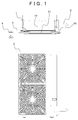
- Fig. 1 is a general view of an overall structure of an air conditioner according to an embodiment of the present invention.
- an indoor unit 1 of ceiling mount type is electrically coupled with an outdoor unit 2 via a refrigerant piping and a transmission line 3.
- the indoor unit 1 performs air conditioning in the room where it is installed.
- the indoor unit 1 is electrically coupled with a remote controller 4 via a remote control transmission line 5.
- the operation command of the indoor unit 1 is activated by the user's operation of the remote controller 4.
- the outdoor unit 2 includes a not shown compressor serving as a heat source, an outdoor heat exchanger for performing heat exchange between outdoor air and working fluid, and an outdoor fan for blowing air to the outdoor heat exchanger.
- Fig. 2 is a perspective view of the indoor unit 1 when seen from below.
- the indoor unit 1 includes a main body part 10 and a decorative panel 11 which covers the lower surface of the main body part 10, which faces the indoor side.
- the main body part 10 is embedded into the ceiling so that the decorative panel 11 is exposed from the ceiling surface.
- the indoor unit 1 includes an indoor fan and a heat exchanger inside, which are not shown in the drawing.
- the indoor fan takes in the indoor air from a suction port 22 of the indoor unit 1 so that the taken air passes through the heat exchanger for heat exchange between air and the refrigerant.
- the conditioned air is blown through four outlet ports 20a to 20d for air conditioning inside the room.
- Louvers 21a to 21d are configured to allow air blow direction of air blown from the respective outlet ports 20a to 20d to be variable in the indoor height direction.
- a human detection sensor 35 is disposed in the decorative panel 11 for the purpose of acquiring human detection information upon air condition with respect to presence or absence of any human in the air conditioned space, or the information indicating the degree of the human's motion.
- the human detection sensor 35 is constituted by the infrared sensor, the sensor performs detection upon change in the infrared light in the detection range resulting from the human motion.
- An indoor control section 13 (not shown) serves to change the set temperature for air conditioning, the air volume of the indoor unit, and each angle of the louvers 21a to 21d based on the human detection information. This makes it possible to prevent excessive cooling, excessive heating, and to improve comfort of the human in the air conditioned space.
- the human detection sensor 35 obtains the detection information data of humans in divided sections of the air conditioned space. Therefore, there may be the case where a plurality of human detection sensors are disposed in the single indoor unit 1.
- each detection range of the plurality of human detection sensors is set corresponding to air condition ranges 26a to 26d (see Fig. 8 ) of the outlet ports 20a to 20d, respectively.
- each air condition in the respective air condition ranges 26a to 26d may be performed individually, for example, by allowing the louver 21a to be operated in response to the human detection information which covers the air condition range 26a, the louver 21b to be operated in response to the human detection information which covers the air condition range 26b, and the like.
- Each of the air condition ranges 26a to 26d has a fan-like conic section. Meanwhile, each detection range of the general purpose human detection sensor, and the human detection sensor lens has a circular conic section. Therefore, the general purpose human detection sensor and the lens thereof cannot be used adaptively to the air condition ranges 26a to 26d. In other words, there may cause the problem of controlling the louver 21 upon human detection even in the range out of the air condition ranges 26a to 20d.
- the combination of the general purpose human detection sensor and the lens which have the detection range with the circular conic section may cause an overlapped section. Therefore, a plurality of human detection sensors may detect the same human in an overlapped manner. It is necessary to use the exclusive human detection sensor or the exclusive human detection sensor lens adapted to the air condition ranges 26a to 26d, respectively.
- the following is the description of structure of the air conditioner according to the embodiment, which is configured to solve the aforementioned problem.
- FIGS. 3 to 6 are enlarged views each representing a position at which the human detection sensor 35 is installed in the indoor unit 1.
- the human detection sensor 35 is disposed on a seat 33 for the human detection sensor, having a mount portion of the human detection sensor formed at a predetermined angle.
- four human detection sensors 35a to 35d are disposed.
- the human detection sensors 35a to 35d are provided with lenses 36a to 36d, respectively to expand (or narrow) the respective detection ranges by refracting the incident infrared light with the predetermined refractive index. This allows the human detection sensors 35a to 35d to perform detection of the predetermined ranges, respectively.
- an infrared shielding cover 32 is disposed over the lenses 36a to 36d for shielding the light incident on the human detection sensor 35 in a part of the range.
- the infrared shielding cover 32 is configured to shield the incident light on the human detection sensor 35 from outside an air condition range 26 (outlet direction) of the outlet port 20 corresponding to the human detection sensor 35.
- the infrared shielding cover 32 is made of a material that does not transmit the infrared light, for example, polystyrene and iron.
- the infrared shielding cover 32 includes openings 53a to 53d each positioned corresponding to the respective human detection sensors 35. Therefore, the infrared light that has passed through the openings 53a to 53d of the infrared shielding cover 32 is only incident on the human detection sensors 35a to 35d.
- an infrared transmission cover 31 is disposed over the lenses 36a to 36d in consideration of both protection and design property of the human detection sensor.
- the infrared transmission cover 31 is made of the material that transmits the infrared light, for example, high density polyethylene so as not to shield the infrared light detected by the human detection sensor 35.
- Fig. 7 as a sectional view of the human detection sensor section, the seat 33 for the human detection sensor, the human detection sensor 35, the lens 36, the infrared shielding cover 32, and the infrared transmission cover 31 are sequentially arranged in order from the inside.
- Air condition ranges 26a to 26d refer to ranges to which air blown from the outlet port 20 by the louvers 21a to 21d reaches.
- Detection ranges 50a to 50d refer to the ranges which allow the respective human detection sensors 35a to 35d provided with the lenses 36a to 36d, respectively for human detection. In other words, in the aforementioned range, the human detection sensors 35a to 35d, and the lenses 36a to 36d for the human detection sensors are allowed to detect change in the infrared light in a certain range resulting from movement of the human.
- Each of the detection ranges 50a to 50d may be the same, or different from one another.
- Shielding ranges 51 within the detection ranges 50a to 50d of the human detection sensors 35a to 35d, and the lenses 36a to 36d for the human detection sensors, which are covered with the infrared shielding cover 32 do not allow detection by the human detection sensors 35a to 35d in spite of change in the infrared light.
- Non-shielding ranges 52 within the detection ranges 50a to 50d of the human detection sensors 35a to 35d, and the lenses 36a to 36d for the human detection sensors, which are covered with the infrared transmission cover 31 allow detection by the human detection sensors 35a to 35d in response to the change in the infrared light.
- each of the detection ranges 50a to 50d expands while forming a circular cone shape to extend to the outside of the air condition ranges 26a to 26d as shown in Fig. 8 .
- the infrared shielding cover 32 includes an opening 53 in order to keep the detection ranges 50a to 50d of the respective human detection sensors to be within ranges corresponding to the respective air condition ranges 26a to 26d. That is, the detection ranges 50a to 50d of the human detection sensors outside the air condition ranges 26a to 26d are shielded. Referring to the detection range 50c as shown in Fig.
- the infrared shielding cover 32 serves to shield the range outside the air condition range 26, and the range as an overlapped part between the detection range 50c of the human detection sensor within the air condition range 26, and the air condition ranges 26b, 26d of the outlet ports 20b, 20d corresponding to the other human detection sensors 35b, 35d so as to correspond the non-shielding range 52c of the detection range 50c to the air condition range 26c.
- the aforementioned structure allows equalization of the detection ranges 50a to 50d of the respective human detection sensors to the corresponding air condition ranges 26a to 26d substantially.
- the human detection sensors 35a to 35d are capable of detecting humans within the corresponding air condition ranges 26a to 26d, respectively.
- the embodiment is configured to provide the lenses 36 for the respective human detection sensors 35 for detection of ranges corresponding to the different outlet ports 20, and to further shield the detection ranges 50 of the human detection sensor 35 outside the air condition ranges 26 by using the infrared shielding cover 32. This makes it possible to ensure desired detection range by using the general purpose products.
- Fig. 1 is a general view showing an overall structure of the embodiment. The description of the same features as those of the first embodiment will be omitted.
- the human detection sensors 35a to 35d send the respective human detection information data 62a to 62d to an indoor control section 13 by which the louvers 63a to 63d corresponding to the respective human detection information data 62a to 62d are operated.
- the louver 21a of the outlet port, the air condition range 26a corresponding to the outlet port 20a, and the human detection sensor 35a are arranged facing the same direction.
- the louver 21a of the outlet port is operated in accordance with the human detection information 62a of the human detection sensor 35a.
- the louvers 21b, 21c, 21d of the outlet ports are operated in accordance with the human detection sensors 35b, 35c, 35d, respectively.
- the corner cover 30 with human detection sensor is not allowed to change its position from the initial corner cover mount portion.
- the louver 21b of the outlet port will be operated in accordance with the human detection information 62a of the human detection sensor 35a, thus shifting the correlation between the human detection sensor and the louver by the angle of 90°.
- the position of the corner cover 30 with the human detection sensor cannot be changed in the on-site work.
- the plurality of indoor units 1 are disposed in the same space, there may be the case of requiring to change the position of the corner cover 30 for consistency from the design aspect.
- the corner cover 30 with human detection sensor is configured to be mountable on any of the corner cover mount portions 24a to 24d as Fig. 9 shows.
- the other corner cover 23 is also mountable on any of the mount portions 24a to 24d.
- the corner cover 30 with human detection sensor has substantially the same shape as that of the corner cover 23, both of which have mount portions corresponding to the mount portions 24a to 24d.
- the remote controller 4 has set items 60 for remote control, while having options 61 corresponding to the set item 60.
- “b1" is selected as the set item 60
- “00” is set as the option 61.
- the option 61 includes "01", “02", “03” in addition to "00".
- the set item 60 set as “b1” may be expressed as an arbitrary code, or arbitrarily expressed as, for example, "sensor mount position".
- the option 61 may be expressed as arbitrary codes, for example, A to D. In this case, it is only necessary to determine the set items 60 and the options 61. The option 61 may be changed upon the on-site work.
- the indoor control section uses the human detection information 62a of the human detection sensor to operate the louver 21a, the human detection information 62b of the human detection sensor to operate the louver 21b, the human detection information 62c of the human detection sensor to operate the louver 21c, and the human detection information 62d of the human detection sensor to operate the louver 21d, respectively.
- the indoor unit control section uses the human detection information 62a of the human detection sensor to operate the louver 21b, the human detection information 62b of the human detection sensor to operate the louver 21c, the human detection information 62c of the human detection sensor to operate the louver 21d, and the human detection information 62d of the human detection sensor to operate the louver 21a, respectively.
- the indoor control section uses the human detection information 62a of the human detection sensor to operate the louver 21c, the human detection information 62b of the human detection sensor to operate the louver 21d, the human detection information 62c of the human detection sensor to operate the louver 21a, and the human detection information 62d of the human detection sensor to operate the louver 21b, respectively.
- the indoor control section uses the human detection information 62a of the human detection sensor to operate the louver 21d, the human detection information 62b of the human detection sensor to operate the louver 21a, the human detection information 62c of the human detection sensor to operate the louver 21b, and the human detection information 62d of the human detection sensor to operate the louver 21c, respectively.
- the structure according to the embodiment becomes operable by setting the option 61 to "00".
- the structure becomes operable by setting the option 61 to "01", "02", or "03", respectively.
- the aforementioned embodiment is configured to allow shifting of the set arrangement correlation between the human detection sensor and the louver at every 90° so as to ensure change in the position of the corner cover 30 with human detection sensor from the initial corner cover mount portion.
- the indoor control section 13 is configured to control the arrangement correlation between the plurality of human detection sensors 35 and the plurality of outlet ports 20. Upon installation of the plurality of indoor units 1 in the same space, the use of the aforementioned indoor control section allows change in the position of the corner cover 30 in the case of the on-site work for consistency from the design aspect.
- Marks 25 from A to D are provided at the corner cover mount portions 24a to 24d on the decorative panel 11, respectively so as to allow the option 61 for the set items of the remote controller 4 to be similarly set to A to D, respectively.
- the corner cover 30 with human detection sensor is disposed over any one of the corner cover mount portions 24a to 24d, which is marked A, the on-site work may be further simplified by selecting "A" as the option 61 for the set item.
- the present invention is not limited to the embodiments as described above, but includes various modifications.
- the embodiments are described in detail for readily understanding of the present invention which is not necessarily limited to the one equipped with all structures as described above. It is possible to replace a part of the structure of one embodiment with the structure of another embodiment.
- the one embodiment may be provided with an additional structure of another embodiment. It is further possible to add, remove, and replace the other structure to, from and with a part of the structure of the respective embodiments.
Landscapes
- Engineering & Computer Science (AREA)
- Chemical & Material Sciences (AREA)
- Combustion & Propulsion (AREA)
- Mechanical Engineering (AREA)
- General Engineering & Computer Science (AREA)
- Human Computer Interaction (AREA)
- Air Conditioning Control Device (AREA)
- Air Filters, Heat-Exchange Apparatuses, And Housings Of Air-Conditioning Units (AREA)
Abstract
Description
- The present invention relates to an indoor unit of an air conditioner, and the air conditioner.
-
JP-A-2011-174693 indoor unit 4 for theair conditioning device 1 is mounted in a ceiling of the air-conditioned room, and has thecasing 51 and a plurality ofhuman detection sensors 62a-62d. Thecasing 51 has the plurality of outlets 56a to 56d through which the conditioned air is blown into the air-conditioned room. Thehuman detection sensors 62a to 62d are provided in thecasing 51 so as to correspond to the outlets 56a to 56d, respectively, and detect presence or absence of humans in the air-conditioned room. Detection areas A, B, C, D for the respectivehuman detection sensors 62a to 62d are aligned with outlet areas A' , B' , C' , D' to which the air flow of the conditioned air blown out from the outlets 56a to 56d reaches."(see Abstract). - PTL 1:
JP-A-2011-174693 - The method disclosed in
Patent Literature 1 requires the use of the exclusive human detection sensor or the human detection sensor lens in order to acquire the detection areas of the respective human detection sensors adapted to the outlet area to which the flow of the conditioned air blown from each of the outlets reaches. In other words, the use of a plurality of human detection sensors requires the exclusive human detection sensors or exclusive human detection sensor lenses for covering those sensors, leading to increased cost. The aforementioned configuration cannot be applied to the other air conditioning system having another outlet area. For example, the human detection sensor or the human detection sensor lens exclusive to the air conditioning system having four outlet areas cannot be applied to the air conditioning system having two outlet areas. - It is an object of the present invention to provide an indoor unit of an air conditioner, which includes a human detection sensor configured to ensure detection of a predetermined range, and detection of the desired number of ranges by using a general purpose human detection sensor and the lens for the human detection sensor for covering the single range, and the air conditioner.
- In order to solve the aforementioned problem, the configuration as described in the claim may be employed. An example as one of solutions to the problem will be described as follows. An indoor unit of air conditioner includes a plurality of outlet ports through which air is blown to an interior of a room in different directions, and a human detection unit for detecting a human in the room. The human detection unit includes a plurality of human detection sensors installed in the plurality of outlet ports correspondingly, and lenses provided for the human detection sensors, respectively. The plurality of human detection sensors detect ranges corresponding to the different outlet ports, respectively. Advantageous Effects of Invention
- The present invention provides an indoor unit of an air conditioner configured to have a plurality of human detection sensors and lenses for covering the respective human detection sensors. The use of general purpose products for the human detection sensor and the lens for covering the single range ensures to detect the desired number of ranges. The present invention also provides the air conditioner. Any problem, structure and advantageous effect other than those described above will be clarified by the following description of the embodiments.
-
-
Fig. 1 is a general view of an air conditioner according to an embodiment of the present invention. -
Fig. 2 is a perspective view of an indoor unit according to the embodiment of the present invention. -
Fig. 3 is a front view showing a state where an infrared transmission cover and an infrared shielding cover of a human detection sensor section, and a lens of the human detection sensor are removed from the indoor unit according to the embodiment of the present invention. -
Fig. 4 is a front view showing a state where the infrared transmission cover and the infrared shielding cover of the human detection sensor section are removed from the indoor unit according to the embodiment of the present invention. -
Fig. 5 is a front view showing a state where the infrared transmission cover of the human detection sensor section is removed from the indoor unit according to the embodiment of the present invention. -
Fig. 6 is a front view of the human detection sensor section of the indoor unit according to the embodiment of the present invention. -
Fig. 7 is a sectional view of the human detection sensor section of the indoor unit according to the embodiment of the present invention. -
Fig. 8 is a schematic view of a detection range covered by the human detection sensor of the indoor unit according to the embodiment of the present invention. -
Fig. 9 is a front view showing a state where corner covers of a decorative panel are removed from the indoor unit according to the embodiment of the present invention. -
Fig. 10 is an enlarged front view showing a state where the corner cover of the decorative panel is removed from the indoor unit according to the embodiment of the present invention. -
Fig. 11 is a view showing a display of a remote controller according to the embodiment of the present invention. -
Fig. 12 is a block diagram for controlling the indoor unit according to the embodiment of the present invention. - Embodiments of an air conditioner according to the present invention will be described referring to
Figs. 1 to 12 . -
Fig. 1 is a general view of an overall structure of an air conditioner according to an embodiment of the present invention. Referring toFig. 1 , anindoor unit 1 of ceiling mount type is electrically coupled with anoutdoor unit 2 via a refrigerant piping and atransmission line 3. Theindoor unit 1 performs air conditioning in the room where it is installed. Theindoor unit 1 is electrically coupled with aremote controller 4 via a remotecontrol transmission line 5. The operation command of theindoor unit 1 is activated by the user's operation of theremote controller 4. Theoutdoor unit 2 includes a not shown compressor serving as a heat source, an outdoor heat exchanger for performing heat exchange between outdoor air and working fluid, and an outdoor fan for blowing air to the outdoor heat exchanger. -
Fig. 2 is a perspective view of theindoor unit 1 when seen from below. Theindoor unit 1 includes amain body part 10 and adecorative panel 11 which covers the lower surface of themain body part 10, which faces the indoor side. Themain body part 10 is embedded into the ceiling so that thedecorative panel 11 is exposed from the ceiling surface. Theindoor unit 1 includes an indoor fan and a heat exchanger inside, which are not shown in the drawing. The indoor fan takes in the indoor air from asuction port 22 of theindoor unit 1 so that the taken air passes through the heat exchanger for heat exchange between air and the refrigerant. The conditioned air is blown through fouroutlet ports 20a to 20d for air conditioning inside the room. Louvers 21a to 21d are configured to allow air blow direction of air blown from therespective outlet ports 20a to 20d to be variable in the indoor height direction. - A
human detection sensor 35 is disposed in thedecorative panel 11 for the purpose of acquiring human detection information upon air condition with respect to presence or absence of any human in the air conditioned space, or the information indicating the degree of the human's motion. In the case where thehuman detection sensor 35 is constituted by the infrared sensor, the sensor performs detection upon change in the infrared light in the detection range resulting from the human motion. An indoor control section 13 (not shown) serves to change the set temperature for air conditioning, the air volume of the indoor unit, and each angle of thelouvers 21a to 21d based on the human detection information. This makes it possible to prevent excessive cooling, excessive heating, and to improve comfort of the human in the air conditioned space. - The
human detection sensor 35 obtains the detection information data of humans in divided sections of the air conditioned space. Therefore, there may be the case where a plurality of human detection sensors are disposed in the singleindoor unit 1. Preferably, each detection range of the plurality of human detection sensors is set corresponding toair condition ranges 26a to 26d (seeFig. 8 ) of theoutlet ports 20a to 20d, respectively. Accordingly, each air condition in the respective air condition ranges 26a to 26d may be performed individually, for example, by allowing thelouver 21a to be operated in response to the human detection information which covers theair condition range 26a, thelouver 21b to be operated in response to the human detection information which covers theair condition range 26b, and the like. - Each of the air condition ranges 26a to 26d has a fan-like conic section. Meanwhile, each detection range of the general purpose human detection sensor, and the human detection sensor lens has a circular conic section. Therefore, the general purpose human detection sensor and the lens thereof cannot be used adaptively to the air condition ranges 26a to 26d. In other words, there may cause the problem of controlling the louver 21 upon human detection even in the range out of the air condition ranges 26a to 20d. The combination of the general purpose human detection sensor and the lens which have the detection range with the circular conic section may cause an overlapped section. Therefore, a plurality of human detection sensors may detect the same human in an overlapped manner. It is necessary to use the exclusive human detection sensor or the exclusive human detection sensor lens adapted to the air condition ranges 26a to 26d, respectively. The following is the description of structure of the air conditioner according to the embodiment, which is configured to solve the aforementioned problem.
- Structure of the human detection sensor section according to an embodiment of the present invention will be described referring to
Figs. 3 to 7. Figs. 3 to 6 are enlarged views each representing a position at which thehuman detection sensor 35 is installed in theindoor unit 1. - As
Fig. 3 shows, thehuman detection sensor 35 is disposed on aseat 33 for the human detection sensor, having a mount portion of the human detection sensor formed at a predetermined angle. In this embodiment, fourhuman detection sensors 35a to 35d are disposed. - Referring to
Fig. 4 , thehuman detection sensors 35a to 35d are provided withlenses 36a to 36d, respectively to expand (or narrow) the respective detection ranges by refracting the incident infrared light with the predetermined refractive index. This allows thehuman detection sensors 35a to 35d to perform detection of the predetermined ranges, respectively. - Referring to
Fig. 5 , aninfrared shielding cover 32 is disposed over thelenses 36a to 36d for shielding the light incident on thehuman detection sensor 35 in a part of the range. Theinfrared shielding cover 32 is configured to shield the incident light on thehuman detection sensor 35 from outside an air condition range 26 (outlet direction) of the outlet port 20 corresponding to thehuman detection sensor 35. - The
infrared shielding cover 32 is made of a material that does not transmit the infrared light, for example, polystyrene and iron. Theinfrared shielding cover 32 includesopenings 53a to 53d each positioned corresponding to the respectivehuman detection sensors 35. Therefore, the infrared light that has passed through theopenings 53a to 53d of theinfrared shielding cover 32 is only incident on thehuman detection sensors 35a to 35d. - Referring to
Fig. 6 , aninfrared transmission cover 31 is disposed over thelenses 36a to 36d in consideration of both protection and design property of the human detection sensor. Theinfrared transmission cover 31 is made of the material that transmits the infrared light, for example, high density polyethylene so as not to shield the infrared light detected by thehuman detection sensor 35. - Referring to
Fig. 7 as a sectional view of the human detection sensor section, theseat 33 for the human detection sensor, thehuman detection sensor 35, thelens 36, theinfrared shielding cover 32, and theinfrared transmission cover 31 are sequentially arranged in order from the inside. - The following is the description of the detection ranges 50a to 50d of the
human detection sensors 35, and the shielding range of theinfrared shielding cover 32 in reference toFig. 8 . - Air condition ranges 26a to 26d refer to ranges to which air blown from the outlet port 20 by the
louvers 21a to 21d reaches. Detection ranges 50a to 50d refer to the ranges which allow the respectivehuman detection sensors 35a to 35d provided with thelenses 36a to 36d, respectively for human detection. In other words, in the aforementioned range, thehuman detection sensors 35a to 35d, and thelenses 36a to 36d for the human detection sensors are allowed to detect change in the infrared light in a certain range resulting from movement of the human. Each of the detection ranges 50a to 50d may be the same, or different from one another. - Shielding ranges 51 within the detection ranges 50a to 50d of the
human detection sensors 35a to 35d, and thelenses 36a to 36d for the human detection sensors, which are covered with theinfrared shielding cover 32 do not allow detection by thehuman detection sensors 35a to 35d in spite of change in the infrared light. Non-shielding ranges 52 within the detection ranges 50a to 50d of thehuman detection sensors 35a to 35d, and thelenses 36a to 36d for the human detection sensors, which are covered with theinfrared transmission cover 31 allow detection by thehuman detection sensors 35a to 35d in response to the change in the infrared light. - In the case of using the general purpose human detection sensor, each of the detection ranges 50a to 50d expands while forming a circular cone shape to extend to the outside of the air condition ranges 26a to 26d as shown in
Fig. 8 . Theinfrared shielding cover 32 includes anopening 53 in order to keep the detection ranges 50a to 50d of the respective human detection sensors to be within ranges corresponding to the respective air condition ranges 26a to 26d. That is, the detection ranges 50a to 50d of the human detection sensors outside the air condition ranges 26a to 26d are shielded. Referring to thedetection range 50c as shown inFig. 8 , theinfrared shielding cover 32 serves to shield the range outside the air condition range 26, and the range as an overlapped part between thedetection range 50c of the human detection sensor within the air condition range 26, and the air condition ranges 26b, 26d of theoutlet ports human detection sensors non-shielding range 52c of thedetection range 50c to theair condition range 26c. - The aforementioned structure allows equalization of the detection ranges 50a to 50d of the respective human detection sensors to the corresponding air condition ranges 26a to 26d substantially. In spite of the use of the general purpose human detection sensors and the lenses thereof, each having the detection range different from the air condition range, the
human detection sensors 35a to 35d are capable of detecting humans within the corresponding air condition ranges 26a to 26d, respectively. - As described above, the embodiment is configured to provide the
lenses 36 for the respectivehuman detection sensors 35 for detection of ranges corresponding to the different outlet ports 20, and to further shield the detection ranges 50 of thehuman detection sensor 35 outside the air condition ranges 26 by using theinfrared shielding cover 32. This makes it possible to ensure desired detection range by using the general purpose products. - In this embodiment, the following is the description with respect to the case of changing the mount portion of the
corner cover 30 with the human detection sensors having the detection ranges adapted to the air condition ranges 26a to 26d, respectively. -
Fig. 1 is a general view showing an overall structure of the embodiment. The description of the same features as those of the first embodiment will be omitted. In the case where the humandetection information data 62a to 62d of the air conditioned space is divisionally acquired, thehuman detection sensors 35a to 35d send the respective humandetection information data 62a to 62d to anindoor control section 13 by which thelouvers 63a to 63d corresponding to the respective humandetection information data 62a to 62d are operated. At this time, thelouver 21a of the outlet port, theair condition range 26a corresponding to theoutlet port 20a, and thehuman detection sensor 35a are arranged facing the same direction. Thelouver 21a of the outlet port is operated in accordance with thehuman detection information 62a of thehuman detection sensor 35a. In the similar manner, thelouvers human detection sensors - In the aforementioned case, the
corner cover 30 with human detection sensor is not allowed to change its position from the initial corner cover mount portion. Assuming that the initial cornercover mount portion 24a is installed at the position corresponding to 24b, thelouver 21b of the outlet port will be operated in accordance with thehuman detection information 62a of thehuman detection sensor 35a, thus shifting the correlation between the human detection sensor and the louver by the angle of 90°. In such a case, the position of thecorner cover 30 with the human detection sensor cannot be changed in the on-site work. Meanwhile, in the case where the plurality ofindoor units 1 are disposed in the same space, there may be the case of requiring to change the position of thecorner cover 30 for consistency from the design aspect. - In this embodiment, the
corner cover 30 with human detection sensor is configured to be mountable on any of the cornercover mount portions 24a to 24d asFig. 9 shows. The other corner cover 23 is also mountable on any of themount portions 24a to 24d. The corner cover 30 with human detection sensor has substantially the same shape as that of thecorner cover 23, both of which have mount portions corresponding to themount portions 24a to 24d. - The
remote controller 4 has setitems 60 for remote control, while havingoptions 61 corresponding to theset item 60. Referring to an example ofFig. 11 , "b1" is selected as theset item 60, and "00" is set as theoption 61. Theoption 61 includes "01", "02", "03" in addition to "00". Theset item 60 set as "b1" may be expressed as an arbitrary code, or arbitrarily expressed as, for example, "sensor mount position". - In the similar manner as described above, the
option 61 may be expressed as arbitrary codes, for example, A to D. In this case, it is only necessary to determine theset items 60 and theoptions 61. Theoption 61 may be changed upon the on-site work. - In the case where the
option 61 is set to "00", the indoor control section uses thehuman detection information 62a of the human detection sensor to operate thelouver 21a, thehuman detection information 62b of the human detection sensor to operate thelouver 21b, thehuman detection information 62c of the human detection sensor to operate thelouver 21c, and thehuman detection information 62d of the human detection sensor to operate thelouver 21d, respectively. - In the case where the
option 61 is set to "01", the indoor unit control section uses thehuman detection information 62a of the human detection sensor to operate thelouver 21b, thehuman detection information 62b of the human detection sensor to operate thelouver 21c, thehuman detection information 62c of the human detection sensor to operate thelouver 21d, and thehuman detection information 62d of the human detection sensor to operate thelouver 21a, respectively. - In the case where the
option 61 is set to "02", the indoor control section uses thehuman detection information 62a of the human detection sensor to operate thelouver 21c, thehuman detection information 62b of the human detection sensor to operate thelouver 21d, thehuman detection information 62c of the human detection sensor to operate thelouver 21a, and thehuman detection information 62d of the human detection sensor to operate thelouver 21b, respectively. - In the case where the
option 61 is set to "03", the indoor control section uses thehuman detection information 62a of the human detection sensor to operate thelouver 21d, thehuman detection information 62b of the human detection sensor to operate thelouver 21a, thehuman detection information 62c of the human detection sensor to operate thelouver 21b, and thehuman detection information 62d of the human detection sensor to operate thelouver 21c, respectively. - In the case where the
corner cover 30 with human detection sensor is mounted on the cornercover mount portion 24a, the structure according to the embodiment becomes operable by setting theoption 61 to "00". Likewise, in the case where the corner cover is mounted on the cornercover mount portion option 61 to "01", "02", or "03", respectively. - The aforementioned embodiment is configured to allow shifting of the set arrangement correlation between the human detection sensor and the louver at every 90° so as to ensure change in the position of the
corner cover 30 with human detection sensor from the initial corner cover mount portion. Theindoor control section 13 is configured to control the arrangement correlation between the plurality ofhuman detection sensors 35 and the plurality of outlet ports 20. Upon installation of the plurality ofindoor units 1 in the same space, the use of the aforementioned indoor control section allows change in the position of thecorner cover 30 in the case of the on-site work for consistency from the design aspect. -
Marks 25 from A to D are provided at the cornercover mount portions 24a to 24d on thedecorative panel 11, respectively so as to allow theoption 61 for the set items of theremote controller 4 to be similarly set to A to D, respectively. In the case where thecorner cover 30 with human detection sensor is disposed over any one of the cornercover mount portions 24a to 24d, which is marked A, the on-site work may be further simplified by selecting "A" as theoption 61 for the set item. - The present invention is not limited to the embodiments as described above, but includes various modifications. For example, the embodiments are described in detail for readily understanding of the present invention which is not necessarily limited to the one equipped with all structures as described above. It is possible to replace a part of the structure of one embodiment with the structure of another embodiment. The one embodiment may be provided with an additional structure of another embodiment. It is further possible to add, remove, and replace the other structure to, from and with a part of the structure of the respective embodiments.
-
- 1:
- indoor unit
- 2:
- outdoor unit
- 3:
- refrigerant piping and transmission line
- 4:
- remote controller
- 5:
- remote control transmission line
- 10:
- main body part of indoor unit
- 11:
- decorative panel
- 12:
- display of remote controller
- 13:
- indoor control section
- 20, 20a, 20b, 20c, 20d:
- outlet port
- 21, 21a, 21b, 21c, 21d:
- louver
- 22:
- suction port
- 23:
- corner cover
- 24, 24a, 24b, 24c, 24d:
- corner cover mount portion
- 25:
- corner cover mark
- 26, 26a, 26b, 26c, 26d:
- air condition range
- 30:
- corner cover with human detection sensor
- 31:
- infrared transmission cover
- 32:
- infrared shielding cover
- 33:
- seat for human detection sensor
- 35, 35a, 35b, 35c, 35d:
- human detection sensor
- 36, 36a, 36n, 36c, 36d:
- lens
- 50, 50a, 50n, 50c, 50d:
- detection range
- 51, 51a, 51b, 51c, 51d:
- shielding range
- 52, 52a, 52b, 52c, 52d:
- non-shielding range
- 53, 53a, 53b, 53c, 53d:
- opening
- 60:
- set item for remote controller
- 61:
- option of set item for remote controller
- 62, 62a, 62b, 62c, 62d:
- human detection information of human detection sensor
- 63, 63a, 63b,63c, 63d:
- operation output of louver
Claims (9)
- An indoor unit of air conditioner, comprising a plurality of outlet ports through which air is blown to an interior of a room in different directions, and a human detection unit for detecting a human in the room, wherein:the human detection unit includes a plurality of human detection sensors installed in the plurality of outlet ports correspondingly, and lenses provided for the human detection sensors, respectively; andthe plurality of human detection sensors detect ranges corresponding to the different outlet ports, respectively.
- The indoor unit of air conditioner according to claim 1, wherein the human detection unit includes a shielding cover that shields a light ray incident on the human detection sensor in a part of the range.
- The indoor unit of air conditioner according to claim 1, wherein the human detection unit includes a shielding cover that shields a light ray incident on the human detection sensor, which is incident on a range other than an air condition range of the outlet port corresponding to the human detection sensor.
- The indoor unit of air conditioner according to claim 1, comprising a shielding cover that shields a range as an overlapped part between a detection range of one of the plurality of human detection sensors and an air condition range of the outlet port corresponding to the other human detection sensor.
- The indoor unit of air conditioner according to claim 1, wherein:the human detection unit includes a shielding cover for shielding a light ray incident on the human detection sensor; andthe shielding cover has openings at positions corresponding to the plurality of human detection sensors, respectively.
- The indoor unit of air conditioner according to claim 2, wherein the human detection unit includes an infrared transmission cover that is made of an infrared transmitting material for covering the plurality of human detection sensors, the lenses, and the shielding cover.
- The indoor unit of air conditioner according to claim 1, comprising a decorative panel applied to a part of a housing as a main body part of the indoor unit, which is exposed to the interior of the room, a plurality of corner covers provided for corners of the decorative panel, and a plurality of mount portions to which the corner covers are attached, wherein:the human detection unit is installed in any one of the plurality of corner covers; andeach of the plurality of corner covers is allowed to be mounted on any one of the mounted portions.
- The indoor unit of air conditioner according to claim 7, comprising a control unit which controls an arrangement correlation between the human detection sensors and the outlet ports.
- An air conditioner comprising the indoor unit according to any one of claims 1 to 8.
Applications Claiming Priority (2)
| Application Number | Priority Date | Filing Date | Title |
|---|---|---|---|
| JP2014009085A JP6241933B2 (en) | 2014-01-22 | 2014-01-22 | Air conditioner indoor unit and air conditioner |
| PCT/JP2014/078430 WO2015111266A1 (en) | 2014-01-22 | 2014-10-27 | Indoor unit of air conditioner and air conditioner |
Publications (3)
| Publication Number | Publication Date |
|---|---|
| EP3098530A1 true EP3098530A1 (en) | 2016-11-30 |
| EP3098530A4 EP3098530A4 (en) | 2017-09-20 |
| EP3098530B1 EP3098530B1 (en) | 2020-11-25 |
Family
ID=53681089
Family Applications (1)
| Application Number | Title | Priority Date | Filing Date |
|---|---|---|---|
| EP14879931.5A Active EP3098530B1 (en) | 2014-01-22 | 2014-10-27 | Indoor unit of air conditioner and air conditioner |
Country Status (4)
| Country | Link |
|---|---|
| US (1) | US20160356518A1 (en) |
| EP (1) | EP3098530B1 (en) |
| JP (1) | JP6241933B2 (en) |
| WO (1) | WO2015111266A1 (en) |
Families Citing this family (9)
| Publication number | Priority date | Publication date | Assignee | Title |
|---|---|---|---|---|
| CN105258293B (en) * | 2015-10-29 | 2018-03-30 | 广东美的制冷设备有限公司 | The air-out control method of air conditioner |
| CN106765540B (en) * | 2016-11-10 | 2022-06-14 | 青岛海尔空调器有限总公司 | Indoor unit of air conditioner |
| US10239381B2 (en) * | 2017-01-23 | 2019-03-26 | TSI Products, Inc. | Vehicle roof fan |
| JP6815303B2 (en) * | 2017-10-31 | 2021-01-20 | 日立グローバルライフソリューションズ株式会社 | Air conditioning reservation system and indoor unit cover |
| JP7049167B2 (en) * | 2018-04-20 | 2022-04-06 | 三菱重工サーマルシステムズ株式会社 | Air conditioner |
| DE112019007616B4 (en) * | 2019-08-08 | 2026-05-21 | Mitsubishi Electric Corporation | air conditioning device |
| US11162705B2 (en) | 2019-08-29 | 2021-11-02 | Hitachi-Johnson Controls Air Conditioning, Inc | Refrigeration cycle control |
| USD969285S1 (en) * | 2020-04-21 | 2022-11-08 | Qingdao Haier Air-Conditioning Electronic Co., Ltd | Outdoor unit of air conditioner |
| JP7707744B2 (en) * | 2021-08-23 | 2025-07-15 | 富士フイルムビジネスイノベーション株式会社 | Image forming device |
Family Cites Families (14)
| Publication number | Priority date | Publication date | Assignee | Title |
|---|---|---|---|---|
| US4671458A (en) * | 1985-02-25 | 1987-06-09 | Kabushiki Kaisha Toshiba | Air conditioning apparatus |
| GB2199658B (en) * | 1986-11-26 | 1990-08-01 | Matsushita Electric Works Ltd | Person-number detecting system |
| JP2760440B2 (en) * | 1989-08-18 | 1998-05-28 | 松下冷機株式会社 | Temperature detector |
| US5107120A (en) * | 1989-09-22 | 1992-04-21 | Pennwalt Corporation | Passive infrared detector |
| US5221919A (en) * | 1991-09-06 | 1993-06-22 | Unenco, Inc. | Room occupancy sensor, lens and method of lens fabrication |
| KR0144897B1 (en) * | 1995-04-25 | 1998-08-01 | 김광호 | Information detection device of an airconditioner |
| JP2004044855A (en) * | 2002-07-09 | 2004-02-12 | Matsushita Electric Works Ltd | Hot wire automatic switch and load control system |
| JP4906579B2 (en) * | 2007-05-08 | 2012-03-28 | 日立アプライアンス株式会社 | Air conditioner |
| JP2009186139A (en) * | 2008-02-08 | 2009-08-20 | Panasonic Corp | Air conditioner |
| JP5216519B2 (en) * | 2008-10-06 | 2013-06-19 | 日立アプライアンス株式会社 | Air conditioner |
| JP2011174693A (en) | 2010-01-26 | 2011-09-08 | Daikin Industries Ltd | Ceiling-mounted indoor unit for air conditioning device |
| JP2011190941A (en) * | 2010-03-12 | 2011-09-29 | Hitachi Appliances Inc | Air conditioner |
| JP5431289B2 (en) * | 2010-10-14 | 2014-03-05 | 三菱電機株式会社 | Air conditioner |
| JP5660060B2 (en) * | 2012-02-10 | 2015-01-28 | ダイキン工業株式会社 | Indoor unit |
-
2014
- 2014-01-22 JP JP2014009085A patent/JP6241933B2/en active Active
- 2014-10-27 US US15/113,061 patent/US20160356518A1/en not_active Abandoned
- 2014-10-27 WO PCT/JP2014/078430 patent/WO2015111266A1/en not_active Ceased
- 2014-10-27 EP EP14879931.5A patent/EP3098530B1/en active Active
Also Published As
| Publication number | Publication date |
|---|---|
| WO2015111266A1 (en) | 2015-07-30 |
| EP3098530B1 (en) | 2020-11-25 |
| JP2015137792A (en) | 2015-07-30 |
| US20160356518A1 (en) | 2016-12-08 |
| JP6241933B2 (en) | 2017-12-06 |
| EP3098530A4 (en) | 2017-09-20 |
Similar Documents
| Publication | Publication Date | Title |
|---|---|---|
| EP3098530B1 (en) | Indoor unit of air conditioner and air conditioner | |
| KR101732181B1 (en) | Smart fire detector | |
| AU2008205868B2 (en) | Air conditioning blow-out panel, air conditioning control system including the same and air conditioning control method | |
| JP6658107B2 (en) | Air conditioning system | |
| JP6767259B2 (en) | Air conditioning system | |
| JP7004508B2 (en) | Air conditioning control device, air conditioner, air conditioning system, air conditioning control method and program | |
| JP2016200311A (en) | Air conditioning system | |
| EP3406982B1 (en) | Air-conditioning device | |
| JP4537903B2 (en) | Air conditioner | |
| CN108474582B (en) | Air conditioning system | |
| JP7083253B2 (en) | Air conditioning system outlet unit and air conditioning system | |
| JP2014145488A (en) | Air conditioner | |
| JP2006226578A (en) | Air conditioning system and control method | |
| AU2015403941B2 (en) | Housing cover and indoor unit of air conditioning apparatus having the housing cover | |
| US20150001307A1 (en) | Heat quantity displaying device and method | |
| JP6138062B2 (en) | Air conditioner | |
| JP5677178B2 (en) | Air conditioner | |
| KR20200136706A (en) | Air conditioner and operating method thereof | |
| ES2872402T3 (en) | Configurable ventilation system | |
| KR101962164B1 (en) | Air-conditioning system and controlling method thereof | |
| JP4943496B2 (en) | Air conditioner | |
| CN210014444U (en) | A comfortable air conditioner | |
| JP2017116231A (en) | Air conditioning system | |
| WO2021049389A1 (en) | Facility device management system | |
| JP6410842B2 (en) | Air conditioner |
Legal Events
| Date | Code | Title | Description |
|---|---|---|---|
| PUAI | Public reference made under article 153(3) epc to a published international application that has entered the european phase |
Free format text: ORIGINAL CODE: 0009012 |
|
| 17P | Request for examination filed |
Effective date: 20160822 |
|
| AK | Designated contracting states |
Kind code of ref document: A1 Designated state(s): AL AT BE BG CH CY CZ DE DK EE ES FI FR GB GR HR HU IE IS IT LI LT LU LV MC MK MT NL NO PL PT RO RS SE SI SK SM TR |
|
| AX | Request for extension of the european patent |
Extension state: BA ME |
|
| DAX | Request for extension of the european patent (deleted) | ||
| A4 | Supplementary search report drawn up and despatched |
Effective date: 20170821 |
|
| RIC1 | Information provided on ipc code assigned before grant |
Ipc: F24F 13/32 20060101ALI20170814BHEP Ipc: F24F 11/02 20060101AFI20170814BHEP |
|
| RAP1 | Party data changed (applicant data changed or rights of an application transferred) |
Owner name: HITACHI-JOHNSON CONTROLS AIR CONDITIONING, INC. |
|
| STAA | Information on the status of an ep patent application or granted ep patent |
Free format text: STATUS: EXAMINATION IS IN PROGRESS |
|
| 17Q | First examination report despatched |
Effective date: 20191119 |
|
| REG | Reference to a national code |
Ref country code: DE Ref legal event code: R079 Ref document number: 602014072796 Country of ref document: DE Free format text: PREVIOUS MAIN CLASS: F24F0011020000 Ipc: F24F0001001400 |
|
| GRAP | Despatch of communication of intention to grant a patent |
Free format text: ORIGINAL CODE: EPIDOSNIGR1 |
|
| STAA | Information on the status of an ep patent application or granted ep patent |
Free format text: STATUS: GRANT OF PATENT IS INTENDED |
|
| RIC1 | Information provided on ipc code assigned before grant |
Ipc: F24F 11/30 20180101ALI20200527BHEP Ipc: F24F 1/0047 20190101ALI20200527BHEP Ipc: F24F 1/0014 20190101AFI20200527BHEP Ipc: F24F 11/79 20180101ALI20200527BHEP |
|
| INTG | Intention to grant announced |
Effective date: 20200624 |
|
| GRAS | Grant fee paid |
Free format text: ORIGINAL CODE: EPIDOSNIGR3 |
|
| GRAA | (expected) grant |
Free format text: ORIGINAL CODE: 0009210 |
|
| STAA | Information on the status of an ep patent application or granted ep patent |
Free format text: STATUS: THE PATENT HAS BEEN GRANTED |
|
| AK | Designated contracting states |
Kind code of ref document: B1 Designated state(s): AL AT BE BG CH CY CZ DE DK EE ES FI FR GB GR HR HU IE IS IT LI LT LU LV MC MK MT NL NO PL PT RO RS SE SI SK SM TR |
|
| REG | Reference to a national code |
Ref country code: GB Ref legal event code: FG4D |
|
| REG | Reference to a national code |
Ref country code: CH Ref legal event code: EP |
|
| REG | Reference to a national code |
Ref country code: DE Ref legal event code: R096 Ref document number: 602014072796 Country of ref document: DE |
|
| REG | Reference to a national code |
Ref country code: AT Ref legal event code: REF Ref document number: 1338783 Country of ref document: AT Kind code of ref document: T Effective date: 20201215 |
|
| REG | Reference to a national code |
Ref country code: IE Ref legal event code: FG4D |
|
| REG | Reference to a national code |
Ref country code: AT Ref legal event code: MK05 Ref document number: 1338783 Country of ref document: AT Kind code of ref document: T Effective date: 20201125 |
|
| REG | Reference to a national code |
Ref country code: NL Ref legal event code: MP Effective date: 20201125 |
|
| PG25 | Lapsed in a contracting state [announced via postgrant information from national office to epo] |
Ref country code: NO Free format text: LAPSE BECAUSE OF FAILURE TO SUBMIT A TRANSLATION OF THE DESCRIPTION OR TO PAY THE FEE WITHIN THE PRESCRIBED TIME-LIMIT Effective date: 20210225 Ref country code: PT Free format text: LAPSE BECAUSE OF FAILURE TO SUBMIT A TRANSLATION OF THE DESCRIPTION OR TO PAY THE FEE WITHIN THE PRESCRIBED TIME-LIMIT Effective date: 20210325 Ref country code: FI Free format text: LAPSE BECAUSE OF FAILURE TO SUBMIT A TRANSLATION OF THE DESCRIPTION OR TO PAY THE FEE WITHIN THE PRESCRIBED TIME-LIMIT Effective date: 20201125 Ref country code: RS Free format text: LAPSE BECAUSE OF FAILURE TO SUBMIT A TRANSLATION OF THE DESCRIPTION OR TO PAY THE FEE WITHIN THE PRESCRIBED TIME-LIMIT Effective date: 20201125 Ref country code: GR Free format text: LAPSE BECAUSE OF FAILURE TO SUBMIT A TRANSLATION OF THE DESCRIPTION OR TO PAY THE FEE WITHIN THE PRESCRIBED TIME-LIMIT Effective date: 20210226 |
|
| PG25 | Lapsed in a contracting state [announced via postgrant information from national office to epo] |
Ref country code: AT Free format text: LAPSE BECAUSE OF FAILURE TO SUBMIT A TRANSLATION OF THE DESCRIPTION OR TO PAY THE FEE WITHIN THE PRESCRIBED TIME-LIMIT Effective date: 20201125 Ref country code: BG Free format text: LAPSE BECAUSE OF FAILURE TO SUBMIT A TRANSLATION OF THE DESCRIPTION OR TO PAY THE FEE WITHIN THE PRESCRIBED TIME-LIMIT Effective date: 20210225 Ref country code: LV Free format text: LAPSE BECAUSE OF FAILURE TO SUBMIT A TRANSLATION OF THE DESCRIPTION OR TO PAY THE FEE WITHIN THE PRESCRIBED TIME-LIMIT Effective date: 20201125 Ref country code: IS Free format text: LAPSE BECAUSE OF FAILURE TO SUBMIT A TRANSLATION OF THE DESCRIPTION OR TO PAY THE FEE WITHIN THE PRESCRIBED TIME-LIMIT Effective date: 20210325 Ref country code: PL Free format text: LAPSE BECAUSE OF FAILURE TO SUBMIT A TRANSLATION OF THE DESCRIPTION OR TO PAY THE FEE WITHIN THE PRESCRIBED TIME-LIMIT Effective date: 20201125 Ref country code: SE Free format text: LAPSE BECAUSE OF FAILURE TO SUBMIT A TRANSLATION OF THE DESCRIPTION OR TO PAY THE FEE WITHIN THE PRESCRIBED TIME-LIMIT Effective date: 20201125 |
|
| REG | Reference to a national code |
Ref country code: LT Ref legal event code: MG9D |
|
| PG25 | Lapsed in a contracting state [announced via postgrant information from national office to epo] |
Ref country code: HR Free format text: LAPSE BECAUSE OF FAILURE TO SUBMIT A TRANSLATION OF THE DESCRIPTION OR TO PAY THE FEE WITHIN THE PRESCRIBED TIME-LIMIT Effective date: 20201125 |
|
| PG25 | Lapsed in a contracting state [announced via postgrant information from national office to epo] |
Ref country code: CZ Free format text: LAPSE BECAUSE OF FAILURE TO SUBMIT A TRANSLATION OF THE DESCRIPTION OR TO PAY THE FEE WITHIN THE PRESCRIBED TIME-LIMIT Effective date: 20201125 Ref country code: EE Free format text: LAPSE BECAUSE OF FAILURE TO SUBMIT A TRANSLATION OF THE DESCRIPTION OR TO PAY THE FEE WITHIN THE PRESCRIBED TIME-LIMIT Effective date: 20201125 Ref country code: SM Free format text: LAPSE BECAUSE OF FAILURE TO SUBMIT A TRANSLATION OF THE DESCRIPTION OR TO PAY THE FEE WITHIN THE PRESCRIBED TIME-LIMIT Effective date: 20201125 Ref country code: RO Free format text: LAPSE BECAUSE OF FAILURE TO SUBMIT A TRANSLATION OF THE DESCRIPTION OR TO PAY THE FEE WITHIN THE PRESCRIBED TIME-LIMIT Effective date: 20201125 Ref country code: SK Free format text: LAPSE BECAUSE OF FAILURE TO SUBMIT A TRANSLATION OF THE DESCRIPTION OR TO PAY THE FEE WITHIN THE PRESCRIBED TIME-LIMIT Effective date: 20201125 Ref country code: LT Free format text: LAPSE BECAUSE OF FAILURE TO SUBMIT A TRANSLATION OF THE DESCRIPTION OR TO PAY THE FEE WITHIN THE PRESCRIBED TIME-LIMIT Effective date: 20201125 |
|
| REG | Reference to a national code |
Ref country code: DE Ref legal event code: R097 Ref document number: 602014072796 Country of ref document: DE |
|
| PG25 | Lapsed in a contracting state [announced via postgrant information from national office to epo] |
Ref country code: DK Free format text: LAPSE BECAUSE OF FAILURE TO SUBMIT A TRANSLATION OF THE DESCRIPTION OR TO PAY THE FEE WITHIN THE PRESCRIBED TIME-LIMIT Effective date: 20201125 |
|
| PLBE | No opposition filed within time limit |
Free format text: ORIGINAL CODE: 0009261 |
|
| STAA | Information on the status of an ep patent application or granted ep patent |
Free format text: STATUS: NO OPPOSITION FILED WITHIN TIME LIMIT |
|
| PG25 | Lapsed in a contracting state [announced via postgrant information from national office to epo] |
Ref country code: AL Free format text: LAPSE BECAUSE OF FAILURE TO SUBMIT A TRANSLATION OF THE DESCRIPTION OR TO PAY THE FEE WITHIN THE PRESCRIBED TIME-LIMIT Effective date: 20201125 Ref country code: NL Free format text: LAPSE BECAUSE OF FAILURE TO SUBMIT A TRANSLATION OF THE DESCRIPTION OR TO PAY THE FEE WITHIN THE PRESCRIBED TIME-LIMIT Effective date: 20201125 Ref country code: IT Free format text: LAPSE BECAUSE OF FAILURE TO SUBMIT A TRANSLATION OF THE DESCRIPTION OR TO PAY THE FEE WITHIN THE PRESCRIBED TIME-LIMIT Effective date: 20201125 |
|
| 26N | No opposition filed |
Effective date: 20210826 |
|
| PG25 | Lapsed in a contracting state [announced via postgrant information from national office to epo] |
Ref country code: SI Free format text: LAPSE BECAUSE OF FAILURE TO SUBMIT A TRANSLATION OF THE DESCRIPTION OR TO PAY THE FEE WITHIN THE PRESCRIBED TIME-LIMIT Effective date: 20201125 Ref country code: ES Free format text: LAPSE BECAUSE OF FAILURE TO SUBMIT A TRANSLATION OF THE DESCRIPTION OR TO PAY THE FEE WITHIN THE PRESCRIBED TIME-LIMIT Effective date: 20201125 |
|
| REG | Reference to a national code |
Ref country code: CH Ref legal event code: PL |
|
| PG25 | Lapsed in a contracting state [announced via postgrant information from national office to epo] |
Ref country code: IS Free format text: LAPSE BECAUSE OF FAILURE TO SUBMIT A TRANSLATION OF THE DESCRIPTION OR TO PAY THE FEE WITHIN THE PRESCRIBED TIME-LIMIT Effective date: 20210325 |
|
| REG | Reference to a national code |
Ref country code: BE Ref legal event code: MM Effective date: 20211031 |
|
| PG25 | Lapsed in a contracting state [announced via postgrant information from national office to epo] |
Ref country code: MC Free format text: LAPSE BECAUSE OF FAILURE TO SUBMIT A TRANSLATION OF THE DESCRIPTION OR TO PAY THE FEE WITHIN THE PRESCRIBED TIME-LIMIT Effective date: 20201125 |
|
| PG25 | Lapsed in a contracting state [announced via postgrant information from national office to epo] |
Ref country code: LU Free format text: LAPSE BECAUSE OF NON-PAYMENT OF DUE FEES Effective date: 20211027 Ref country code: BE Free format text: LAPSE BECAUSE OF NON-PAYMENT OF DUE FEES Effective date: 20211031 |
|
| PG25 | Lapsed in a contracting state [announced via postgrant information from national office to epo] |
Ref country code: LI Free format text: LAPSE BECAUSE OF NON-PAYMENT OF DUE FEES Effective date: 20211031 Ref country code: CH Free format text: LAPSE BECAUSE OF NON-PAYMENT OF DUE FEES Effective date: 20211031 |
|
| PG25 | Lapsed in a contracting state [announced via postgrant information from national office to epo] |
Ref country code: IE Free format text: LAPSE BECAUSE OF NON-PAYMENT OF DUE FEES Effective date: 20211027 |
|
| PG25 | Lapsed in a contracting state [announced via postgrant information from national office to epo] |
Ref country code: HU Free format text: LAPSE BECAUSE OF FAILURE TO SUBMIT A TRANSLATION OF THE DESCRIPTION OR TO PAY THE FEE WITHIN THE PRESCRIBED TIME-LIMIT; INVALID AB INITIO Effective date: 20141027 |
|
| PG25 | Lapsed in a contracting state [announced via postgrant information from national office to epo] |
Ref country code: CY Free format text: LAPSE BECAUSE OF FAILURE TO SUBMIT A TRANSLATION OF THE DESCRIPTION OR TO PAY THE FEE WITHIN THE PRESCRIBED TIME-LIMIT Effective date: 20201125 |
|
| PG25 | Lapsed in a contracting state [announced via postgrant information from national office to epo] |
Ref country code: MK Free format text: LAPSE BECAUSE OF FAILURE TO SUBMIT A TRANSLATION OF THE DESCRIPTION OR TO PAY THE FEE WITHIN THE PRESCRIBED TIME-LIMIT Effective date: 20201125 |
|
| PG25 | Lapsed in a contracting state [announced via postgrant information from national office to epo] |
Ref country code: TR Free format text: LAPSE BECAUSE OF FAILURE TO SUBMIT A TRANSLATION OF THE DESCRIPTION OR TO PAY THE FEE WITHIN THE PRESCRIBED TIME-LIMIT Effective date: 20201125 |
|
| PG25 | Lapsed in a contracting state [announced via postgrant information from national office to epo] |
Ref country code: MT Free format text: LAPSE BECAUSE OF FAILURE TO SUBMIT A TRANSLATION OF THE DESCRIPTION OR TO PAY THE FEE WITHIN THE PRESCRIBED TIME-LIMIT Effective date: 20201125 |
|
| PGFP | Annual fee paid to national office [announced via postgrant information from national office to epo] |
Ref country code: GB Payment date: 20250923 Year of fee payment: 12 |
|
| PGFP | Annual fee paid to national office [announced via postgrant information from national office to epo] |
Ref country code: FR Payment date: 20250924 Year of fee payment: 12 |
|
| PGFP | Annual fee paid to national office [announced via postgrant information from national office to epo] |
Ref country code: DE Payment date: 20250923 Year of fee payment: 12 |