EP3098419A1 - Turbomachiine load coupling device having a natural convection ventilation system - Google Patents
Turbomachiine load coupling device having a natural convection ventilation system Download PDFInfo
- Publication number
- EP3098419A1 EP3098419A1 EP16169929.3A EP16169929A EP3098419A1 EP 3098419 A1 EP3098419 A1 EP 3098419A1 EP 16169929 A EP16169929 A EP 16169929A EP 3098419 A1 EP3098419 A1 EP 3098419A1
- Authority
- EP
- European Patent Office
- Prior art keywords
- load
- turbomachine
- load coupling
- coupling guard
- vent
- Prior art date
- Legal status (The legal status is an assumption and is not a legal conclusion. Google has not performed a legal analysis and makes no representation as to the accuracy of the status listed.)
- Granted
Links
Images


Classifications
-
- F—MECHANICAL ENGINEERING; LIGHTING; HEATING; WEAPONS; BLASTING
- F01—MACHINES OR ENGINES IN GENERAL; ENGINE PLANTS IN GENERAL; STEAM ENGINES
- F01D—NON-POSITIVE DISPLACEMENT MACHINES OR ENGINES, e.g. STEAM TURBINES
- F01D15/00—Adaptations of machines or engines for special use; Combinations of engines with devices driven thereby
- F01D15/10—Adaptations for driving, or combinations with, electric generators
-
- F—MECHANICAL ENGINEERING; LIGHTING; HEATING; WEAPONS; BLASTING
- F02—COMBUSTION ENGINES; HOT-GAS OR COMBUSTION-PRODUCT ENGINE PLANTS
- F02C—GAS-TURBINE PLANTS; AIR INTAKES FOR JET-PROPULSION PLANTS; CONTROLLING FUEL SUPPLY IN AIR-BREATHING JET-PROPULSION PLANTS
- F02C7/00—Features, components parts, details or accessories, not provided for in, or of interest apart form groups F02C1/00 - F02C6/00; Air intakes for jet-propulsion plants
- F02C7/12—Cooling of plants
- F02C7/16—Cooling of plants characterised by cooling medium
- F02C7/18—Cooling of plants characterised by cooling medium the medium being gaseous, e.g. air
-
- F—MECHANICAL ENGINEERING; LIGHTING; HEATING; WEAPONS; BLASTING
- F02—COMBUSTION ENGINES; HOT-GAS OR COMBUSTION-PRODUCT ENGINE PLANTS
- F02C—GAS-TURBINE PLANTS; AIR INTAKES FOR JET-PROPULSION PLANTS; CONTROLLING FUEL SUPPLY IN AIR-BREATHING JET-PROPULSION PLANTS
- F02C7/00—Features, components parts, details or accessories, not provided for in, or of interest apart form groups F02C1/00 - F02C6/00; Air intakes for jet-propulsion plants
-
- F—MECHANICAL ENGINEERING; LIGHTING; HEATING; WEAPONS; BLASTING
- F01—MACHINES OR ENGINES IN GENERAL; ENGINE PLANTS IN GENERAL; STEAM ENGINES
- F01D—NON-POSITIVE DISPLACEMENT MACHINES OR ENGINES, e.g. STEAM TURBINES
- F01D15/00—Adaptations of machines or engines for special use; Combinations of engines with devices driven thereby
-
- F—MECHANICAL ENGINEERING; LIGHTING; HEATING; WEAPONS; BLASTING
- F02—COMBUSTION ENGINES; HOT-GAS OR COMBUSTION-PRODUCT ENGINE PLANTS
- F02C—GAS-TURBINE PLANTS; AIR INTAKES FOR JET-PROPULSION PLANTS; CONTROLLING FUEL SUPPLY IN AIR-BREATHING JET-PROPULSION PLANTS
- F02C3/00—Gas-turbine plants characterised by the use of combustion products as the working fluid
- F02C3/04—Gas-turbine plants characterised by the use of combustion products as the working fluid having a turbine driving a compressor
-
- F—MECHANICAL ENGINEERING; LIGHTING; HEATING; WEAPONS; BLASTING
- F02—COMBUSTION ENGINES; HOT-GAS OR COMBUSTION-PRODUCT ENGINE PLANTS
- F02C—GAS-TURBINE PLANTS; AIR INTAKES FOR JET-PROPULSION PLANTS; CONTROLLING FUEL SUPPLY IN AIR-BREATHING JET-PROPULSION PLANTS
- F02C6/00—Plural gas-turbine plants; Combinations of gas-turbine plants with other apparatus; Adaptations of gas-turbine plants for special use
- F02C6/14—Gas-turbine plants having means for storing energy, e.g. for meeting peak loads
-
- F—MECHANICAL ENGINEERING; LIGHTING; HEATING; WEAPONS; BLASTING
- F02—COMBUSTION ENGINES; HOT-GAS OR COMBUSTION-PRODUCT ENGINE PLANTS
- F02C—GAS-TURBINE PLANTS; AIR INTAKES FOR JET-PROPULSION PLANTS; CONTROLLING FUEL SUPPLY IN AIR-BREATHING JET-PROPULSION PLANTS
- F02C7/00—Features, components parts, details or accessories, not provided for in, or of interest apart form groups F02C1/00 - F02C6/00; Air intakes for jet-propulsion plants
- F02C7/36—Power transmission arrangements between the different shafts of the gas turbine plant, or between the gas-turbine plant and the power user
-
- F—MECHANICAL ENGINEERING; LIGHTING; HEATING; WEAPONS; BLASTING
- F24—HEATING; RANGES; VENTILATING
- F24F—AIR-CONDITIONING; AIR-HUMIDIFICATION; VENTILATION; USE OF AIR CURRENTS FOR SCREENING
- F24F7/00—Ventilation
- F24F7/04—Ventilation with ducting systems, e.g. by double walls; with natural circulation
-
- F—MECHANICAL ENGINEERING; LIGHTING; HEATING; WEAPONS; BLASTING
- F05—INDEXING SCHEMES RELATING TO ENGINES OR PUMPS IN VARIOUS SUBCLASSES OF CLASSES F01-F04
- F05D—INDEXING SCHEME FOR ASPECTS RELATING TO NON-POSITIVE-DISPLACEMENT MACHINES OR ENGINES, GAS-TURBINES OR JET-PROPULSION PLANTS
- F05D2220/00—Application
- F05D2220/30—Application in turbines
- F05D2220/32—Application in turbines in gas turbines
-
- F—MECHANICAL ENGINEERING; LIGHTING; HEATING; WEAPONS; BLASTING
- F05—INDEXING SCHEMES RELATING TO ENGINES OR PUMPS IN VARIOUS SUBCLASSES OF CLASSES F01-F04
- F05D—INDEXING SCHEME FOR ASPECTS RELATING TO NON-POSITIVE-DISPLACEMENT MACHINES OR ENGINES, GAS-TURBINES OR JET-PROPULSION PLANTS
- F05D2240/00—Components
- F05D2240/10—Stators
- F05D2240/14—Casings or housings protecting or supporting assemblies within
-
- F—MECHANICAL ENGINEERING; LIGHTING; HEATING; WEAPONS; BLASTING
- F05—INDEXING SCHEMES RELATING TO ENGINES OR PUMPS IN VARIOUS SUBCLASSES OF CLASSES F01-F04
- F05D—INDEXING SCHEME FOR ASPECTS RELATING TO NON-POSITIVE-DISPLACEMENT MACHINES OR ENGINES, GAS-TURBINES OR JET-PROPULSION PLANTS
- F05D2240/00—Components
- F05D2240/35—Combustors or associated equipment
-
- F—MECHANICAL ENGINEERING; LIGHTING; HEATING; WEAPONS; BLASTING
- F24—HEATING; RANGES; VENTILATING
- F24F—AIR-CONDITIONING; AIR-HUMIDIFICATION; VENTILATION; USE OF AIR CURRENTS FOR SCREENING
- F24F7/00—Ventilation
- F24F2007/004—Natural ventilation using convection
Definitions
- the subject matter disclosed herein relates to the art of turbomachines and, more particularly to a turbomachine load coupling device having a natural convection ventilation system.
- Gas turbomachines typically include a compressor portion, a turbine portion and a combustor assembly.
- the combustor assembly mixes fluid from the compressor portion with a fuel to form a combustible mixture.
- the combustible mixture is combusted forming hot gases that pass along a hot gas path of the turbine portion.
- the turbine portion includes a number of stages having airfoils mounted to rotors that convert thermal energy from the hot gases into mechanical, rotational energy. Additional fluid from the compressor is passed through the airfoils and other sections of the turbine portion for cooling purposes.
- the turbomachine may be coupled to a load, such as a generator, through a load coupling device.
- a load coupling device includes a housing including an interior portion, an ambient air inlet provided in the housing, a load coupling shaft, and a load coupling guard arranged in the housing.
- the load coupling guard includes a turbomachine end and a load end and a passage extending therebetween.
- a vent extends upwardly from the load coupling guard. The vent is fluidically exposed to the load end.
- An ambient air inlet passage is formed in the load coupling guard and fluidically connects the ambient air inlet and the vent.
- the load end is substantially fluidically isolated from the turbomachine end.
- a turbomachine includes a compressor portion, a turbine portion operatively connected to the compressor portion, a combustor assembly fluidically connected to each of the compressor portion and the turbine portion, a load mechanically linked to one of the compressor portion and the turbine portion, and a load coupling device interfacing with the one of the compressor portion and the turbine portion and the load.
- the load coupling device includes a housing including an interior portion, an ambient air inlet provided in the housing, and a load coupling guard arranged in the housing.
- the load coupling guard includes a turbomachine end coupled to the one of the compressor portion and the turbine portion, a load end coupled to the load, and a passage extending therebetween.
- a vent extends upwardly from the load coupling guard. The vent is fluidically exposed to the load end.
- An ambient air inlet passage is formed in the load coupling guard and fluidically connects to the ambient air inlet and the vent.
- the load end is substantially fluidically isolated from the turbomachine end.
- a turbomachine includes a compressor portion, a turbine portion operatively connected to the compressor portion, a combustor assembly fluidically connected to each of the compressor portion and the turbine portion, a load mechanically linked to one of the compressor portion and the turbine portion, an intake system fluidically connected to the compressor portion, and a load coupling device interfacing with the one of the compressor portion and the turbine portion and the load.
- the load coupling device includes a housing including an interior portion, an ambient air inlet provided in the housing, and a load coupling guard arranged in the housing.
- the load coupling guard includes a turbomachine end coupled to the one of the compressor portion and the turbine portion, a load end coupled to the load, and a passage extending therebetween.
- a vent extends upwardly from the load coupling guard.
- the vent is fluidically exposed to the load end.
- An ambient air inlet passage is formed in the load coupling guard and fluidically connects to the ambient air inlet and the vent.
- the load end is substantially fluidically isolated from the turbomachine end.
- a turbomachine system in accordance with an exemplary embodiment, is indicated generally at 2, in FIG. 1 .
- Turbomachine system 2 includes a turbomachine 4 having a compressor portion 6 and a turbine portion 8 operatively connected by a common compressor/turbine shaft 10.
- Compressor portion 6 is also fluidically connected to turbine portion 8 through a combustor assembly 12.
- Combustor assembly 12 includes at least one combustor 14.
- Turbomachine system 2 also includes an intake system 16 fluidically coupled to an intake (not separately labeled) of compressor portion 6. Intake system 16 may condition an airflow passing into compressor portion 6.
- An exhaust system 18 is fluidically connected to an outlet (also not separately labeled) of turbine portion 8 through a diffuser portion 20. Exhaust system 18 may condition exhaust gases passing from turbine portion 8.
- a load coupling device 22 provides an interface between turbomachine 4 and a load 24. Load 24 may take the form of a generator 25 coupled to compressor portion 6 through a load coupling shaft 28. Load coupling shaft 28 provides an interface between common compressor/turbine shaft 10 and a generator input/drive shaft 30. In the embodiment shown, load coupling shaft 28 is joined to generator input/drive shaft 30 through a flange 31.
- An airflow compartment 33 is arranged between load 24 and turbomachine 4. Airflow compartment 33 provides an airflow to load coupling device 22. As will be detailed more fully below, load coupling device 22 limits gases, such as hydrogen, produced in load 24, from passing into airflow compartment 33.
- load coupling device 22 fluidically connected with a housing or inlet plenum enclosure 40 having an interior portion 42.
- Housing 40 includes an ambient air inlet 45 and an ambient air outlet 48.
- Ambient air outlet 48 may direct ambient air into a turbomachine compartment (not shown) housing turbomachine 4.
- An air-to-load coupling compartment 50 may reside within interior portion 42.
- load coupling device 22 houses a load coupling guard 60.
- load coupling guard 60 includes a body 62 having a turbomachine end 63 operatively coupled to compressor portion 6 through a flange 64 and a load end 65 operatively connected to load 24.
- Load coupling guard 60 may also include grounding brushes (not shown).
- load coupling guard 60 includes a passage 67 that extends between turbomachine end 63 and load end 65. Passage 67 is receptive of load coupling shaft 28 that operatively connects load 24 and turbomachine 4. Passage 67 includes an inner surface 78 from which extends a baffle member 80 that limits a flow of gases from load 24 to turbomachine 4. Baffle member 80 extends radially inwardly into passage 67 to prevent gases from flowing from load end 65 to turbomachine end 63. At this point, it should be understood that the number and location of baffle member 80 may vary. For instance, load coupling guard 60 may include a baffle member arranged both upstream and downstream of flange 31.
- load coupling guard 60 includes a vent 90 that may extend upwardly from body 62.
- Vent 90 includes an inlet 92 fluidically connected to passage 67 and an outlet 93.
- Vent 90 is sized to establish a chimney effect sufficient to overcome any negative pressure in passage 67. The chimney effect draws in ambient air flowing through load coupling guard 60 and gases passing from load 24.
- vent 90 cooperates with baffle member 80 to still further prevent gases passing from load 24 into turbomachine 4.
- the use of vent 90 coupled with ambient air, establishes a natural convective flow that reduces or eliminates the need for costly plumbing and other systems to introduce an airflow into load coupling guard 60.
Landscapes
- Engineering & Computer Science (AREA)
- Chemical & Material Sciences (AREA)
- Combustion & Propulsion (AREA)
- Mechanical Engineering (AREA)
- General Engineering & Computer Science (AREA)
- Structures Of Non-Positive Displacement Pumps (AREA)
Abstract
Description
- The subject matter disclosed herein relates to the art of turbomachines and, more particularly to a turbomachine load coupling device having a natural convection ventilation system.
- Gas turbomachines typically include a compressor portion, a turbine portion and a combustor assembly. The combustor assembly mixes fluid from the compressor portion with a fuel to form a combustible mixture. The combustible mixture is combusted forming hot gases that pass along a hot gas path of the turbine portion. The turbine portion includes a number of stages having airfoils mounted to rotors that convert thermal energy from the hot gases into mechanical, rotational energy. Additional fluid from the compressor is passed through the airfoils and other sections of the turbine portion for cooling purposes. Oftentimes, the turbomachine may be coupled to a load, such as a generator, through a load coupling device.
- According to one aspect of an exemplary embodiment, a load coupling device includes a housing including an interior portion, an ambient air inlet provided in the housing, a load coupling shaft, and a load coupling guard arranged in the housing. The load coupling guard includes a turbomachine end and a load end and a passage extending therebetween. A vent extends upwardly from the load coupling guard. The vent is fluidically exposed to the load end. An ambient air inlet passage is formed in the load coupling guard and fluidically connects the ambient air inlet and the vent. The load end is substantially fluidically isolated from the turbomachine end.
- According to another aspect of an exemplary embodiment, a turbomachine includes a compressor portion, a turbine portion operatively connected to the compressor portion, a combustor assembly fluidically connected to each of the compressor portion and the turbine portion, a load mechanically linked to one of the compressor portion and the turbine portion, and a load coupling device interfacing with the one of the compressor portion and the turbine portion and the load. The load coupling device includes a housing including an interior portion, an ambient air inlet provided in the housing, and a load coupling guard arranged in the housing. The load coupling guard includes a turbomachine end coupled to the one of the compressor portion and the turbine portion, a load end coupled to the load, and a passage extending therebetween. A vent extends upwardly from the load coupling guard. The vent is fluidically exposed to the load end. An ambient air inlet passage is formed in the load coupling guard and fluidically connects to the ambient air inlet and the vent. The load end is substantially fluidically isolated from the turbomachine end.
- According to yet another aspect of an exemplary embodiment, a turbomachine includes a compressor portion, a turbine portion operatively connected to the compressor portion, a combustor assembly fluidically connected to each of the compressor portion and the turbine portion, a load mechanically linked to one of the compressor portion and the turbine portion, an intake system fluidically connected to the compressor portion, and a load coupling device interfacing with the one of the compressor portion and the turbine portion and the load. The load coupling device includes a housing including an interior portion, an ambient air inlet provided in the housing, and a load coupling guard arranged in the housing. The load coupling guard includes a turbomachine end coupled to the one of the compressor portion and the turbine portion, a load end coupled to the load, and a passage extending therebetween. A vent extends upwardly from the load coupling guard. The vent is fluidically exposed to the load end. An ambient air inlet passage is formed in the load coupling guard and fluidically connects to the ambient air inlet and the vent. The load end is substantially fluidically isolated from the turbomachine end.
- These and other advantages and features will become more apparent from the following description taken in conjunction with the drawings.
- The subject matter, which is regarded as the invention, is particularly pointed out and distinctly claimed in the claims at the conclusion of the specification. The foregoing and other features, and advantages of the invention are apparent from the following detailed description taken in conjunction with the accompanying drawings in which:
-
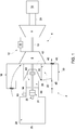
FIG. 1 is a schematic representation of a turbomachine system including a load coupling device, in accordance with an exemplary embodiment; -
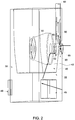
FIG. 2 depicts the load coupling device, in accordance with an exemplary embodiment; -
FIG. 3 depicts a load coupling guard of the load coupling device, in accordance with an exemplary embodiment; and -
FIG. 4 depicts a partial cross-sectional side view of the load coupling guard, in accordance with an exemplary embodiment. - The detailed description explains embodiments of the invention, together with advantages and features, by way of example with reference to the drawings.
- A turbomachine system, in accordance with an exemplary embodiment, is indicated generally at 2, in
FIG. 1 .Turbomachine system 2 includes aturbomachine 4 having a compressor portion 6 and aturbine portion 8 operatively connected by a common compressor/turbine shaft 10. Compressor portion 6 is also fluidically connected toturbine portion 8 through acombustor assembly 12.Combustor assembly 12 includes at least onecombustor 14.Turbomachine system 2 also includes anintake system 16 fluidically coupled to an intake (not separately labeled) of compressor portion 6.Intake system 16 may condition an airflow passing into compressor portion 6. - An
exhaust system 18 is fluidically connected to an outlet (also not separately labeled) ofturbine portion 8 through adiffuser portion 20.Exhaust system 18 may condition exhaust gases passing fromturbine portion 8. Aload coupling device 22 provides an interface betweenturbomachine 4 and aload 24.Load 24 may take the form of agenerator 25 coupled to compressor portion 6 through aload coupling shaft 28.Load coupling shaft 28 provides an interface between common compressor/turbine shaft 10 and a generator input/drive shaft 30. In the embodiment shown,load coupling shaft 28 is joined to generator input/drive shaft 30 through aflange 31. Anairflow compartment 33 is arranged betweenload 24 andturbomachine 4.Airflow compartment 33 provides an airflow to loadcoupling device 22. As will be detailed more fully below,load coupling device 22 limits gases, such as hydrogen, produced inload 24, from passing intoairflow compartment 33. - In accordance with an aspect of an exemplary embodiment illustrated in
FIGs. 2-4 ,load coupling device 22 fluidically connected with a housing orinlet plenum enclosure 40 having aninterior portion 42.Housing 40 includes anambient air inlet 45 and anambient air outlet 48.Ambient air outlet 48 may direct ambient air into a turbomachine compartment (not shown)housing turbomachine 4. An air-to-load coupling compartment 50 may reside withininterior portion 42. In addition,load coupling device 22 houses aload coupling guard 60. In accordance with an aspect of an exemplary embodiment,load coupling guard 60 includes abody 62 having a turbomachine end 63 operatively coupled to compressor portion 6 through aflange 64 and aload end 65 operatively connected toload 24.Load coupling guard 60 may also include grounding brushes (not shown). - In still further accordance with an exemplary embodiment,
load coupling guard 60 includes apassage 67 that extends betweenturbomachine end 63 andload end 65. Passage 67 is receptive ofload coupling shaft 28 that operatively connectsload 24 andturbomachine 4.Passage 67 includes aninner surface 78 from which extends abaffle member 80 that limits a flow of gases fromload 24 toturbomachine 4. Bafflemember 80 extends radially inwardly intopassage 67 to prevent gases from flowing fromload end 65 toturbomachine end 63. At this point, it should be understood that the number and location ofbaffle member 80 may vary. For instance,load coupling guard 60 may include a baffle member arranged both upstream and downstream offlange 31. - In still yet further accordance with an exemplary embodiment,
load coupling guard 60 includes avent 90 that may extend upwardly frombody 62.Vent 90 includes aninlet 92 fluidically connected topassage 67 and anoutlet 93.Vent 90 is sized to establish a chimney effect sufficient to overcome any negative pressure inpassage 67. The chimney effect draws in ambient air flowing throughload coupling guard 60 and gases passing fromload 24. In this manner, vent 90 cooperates withbaffle member 80 to still further prevent gases passing fromload 24 intoturbomachine 4. In addition, the use ofvent 90, coupled with ambient air, establishes a natural convective flow that reduces or eliminates the need for costly plumbing and other systems to introduce an airflow intoload coupling guard 60. - The term "about" is intended to include the degree of error associated with measurement of the particular quantity based upon the equipment available at the time of filing the application. For example, "about" can include a range of ± 8% or 5%, or 2% of a given value.
- The terminology used herein is for the purpose of describing particular embodiments only and is not intended to be limiting of the invention. As used herein, the singular forms "a", "an" and "the" are intended to include the plural forms as well, unless the context clearly indicates otherwise. It will be further understood that the terms "comprises" and/or "comprising," when used in this specification, specify the presence of stated features, integers, steps, operations, elements, and/or components, but do not preclude the presence or addition of one more other features, integers, steps, operations, element components, and/or groups thereof.
- While the invention has been described in detail in connection with only a limited number of embodiments, it should be readily understood that the invention is not limited to such disclosed embodiments. Rather, the invention can be modified to incorporate any number of variations, alterations, substitutions or equivalent arrangements not heretofore described, but which are commensurate with the scope of the invention. Additionally, while various embodiments of the invention have been described, it is to be understood that aspects of the invention may include only some of the described embodiments. Accordingly, the invention is not to be seen as limited by the foregoing description, but is only limited by the scope of the appended claims.
Claims (15)
- A load coupling device (22) comprising:a housing (40) including an interior portion (42);an ambient air inlet (45) provided in the housing (40);a load coupling guard (60) arranged in the housing (40), the load coupling guard (60) including a turbomachine end (63) and a load end (65) and a passage (67) extending therebetween;a vent (90) extending upwardly from the load coupling guard (60), the vent (90) being fluidically exposed to the load end (65); andan ambient air inlet passage formed in the load coupling guard (60) and fluidically connecting the ambient air inlet (45) and the vent (90), wherein the load end (65) is substantially fluidically isolated from the turbomachine end (63).
- The load coupling device (22) according to claim 1, wherein the load coupling guard (60) includes at least one baffle member (80) extending into the passage (67), the at least one baffle member (80) further preventing gases entering the load end (65) from passing to the turbomachine end (63).
- The load coupling device (22) according to claim 2, wherein the at least one baffle member (80) extends radially inwardly into the passage (67).
- A turbomachine (4) comprising:a compressor portion (6);a turbine portion (8) operatively connected to the compressor portion (6);a combustor assembly (12) fluidically connected to each of the compressor portion (6) and the turbine portion (8);a load (24) mechanically linked to one of the compressor portion (6) and the turbine portion (8); anda load coupling device (22) interfacing with the one of the compressor portion (6) and the turbine portion (8) and the load (24), the load coupling device (22) comprising:a housing (40) including an interior portion (42);an ambient air inlet (45) provided in the housing (40);a load coupling guard (60) arranged in the housing (40), the load coupling guard (60) including a turbomachine end (63) coupled to the one of the turbine portion (8) and the compressor portion (6), a load end (65) coupled to the load (24), and a passage (67) extending therebetween;a vent (90) extending upwardly from the load coupling guard (60), the vent (90) being fluidically exposed to the load end (65); andan ambient air inlet passage formed in the load coupling guard (60) and fluidically connecting the ambient air inlet (45) and the vent (90), wherein the load end (65) is substantially fluidically isolated from the turbomachine end (63).
- The turbomachine (4) according to claim 4, wherein the load coupling guard (60) further includes at least one baffle member (80) extending into the passage (67), the at least one baffle member (80) further preventing gases entering the load end (65) from passing to the turbomachine end (63).
- The turbomachine (4) according to claim 5, wherein the at least one baffle member (80) extends radially inwardly into the passage (67).
- The turbomachine (4) according to claim 4, 5 or 6, wherein the load (24) is mechanically linked to the turbine portion (8) through a shaft (28) extending through the load coupling guard (60).
- The turbomachine (4) according to claim 4, 5 or 6, further comprising: an air flow compartment (33) arranged between the load (24) and the turbomachine (4), wherein the load coupling device (22) is mounted in the air flow compartment (33).
- The turbomachine (4) according to any of claims 4 to 8, wherein the load (24) comprises a generator (25).
- A turbomachine system (2) comprising:a compressor portion (6);a turbine portion (8) operatively connected to the compressor portion (6);a combustor assembly (12) fluidically connected to each of the compressor portion (6) and the turbine portion (8);an intake system (16) fluidically connected to the compressor portion (6);a load (24) mechanically linked to one of the compressor portion (6) and the turbine portion (8); anda load coupling device (22) interfacing with the one of the compressor portion (6) and the turbine portion (8) and the load (24), the load coupling device (22) comprising:a housing (40) including an interior portion (42);an ambient air inlet (45) provided in the housing (40);a load coupling guard (60) arranged in the housing (40), the load coupling guard (60) including a turbomachine end (63) coupled to the one of the turbine portion (8) and the compressor portion (6), a load end (65) coupled to the load (24), and a passage (67) extending therebetween;a vent (90) extending upwardly from the load coupling guard (60), the vent (90) being fluidically exposed to the load end (65); andan ambient air inlet passage formed in the load coupling guard (60) and fluidically connecting the ambient air inlet (45) and the vent (90), wherein the load end (65) is substantially fluidically isolated from the turbomachine end (63).
- The turbomachine system (2) according to claim 10, wherein the load coupling guard (60) further includes at least one baffle member (80) extending into the passage (67), the at least one baffle member (80) further preventing gases entering the load end (65) from passing to the turbomachine end (63).
- The turbomachine system (2) according to claim 11, wherein the at least one baffle member (80) extends radially inwardly into the passage (67).
- The turbomachine system (2) according to claim 10, 11 or 12, wherein the load (24) is mechanically linked to the turbine portion (8) through a shaft (28) extending through the load coupling guard (60).
- The turbomachine system (2) according to claim 10, 11 or 12, further comprising: an airflow compartment (33) arranged between the load (24) and the turbomachine (4), wherein the load coupling device (22) is mounted in the airflow compartment (33).
- The turbomachine system (2) according to any of claims 10 to 14, wherein the load (24) comprises a generator (25).
Applications Claiming Priority (1)
| Application Number | Priority Date | Filing Date | Title |
|---|---|---|---|
| US14/721,355 US20160348584A1 (en) | 2015-05-26 | 2015-05-26 | Turbomachine load coupling device having a natural convection ventilation system |
Publications (2)
| Publication Number | Publication Date |
|---|---|
| EP3098419A1 true EP3098419A1 (en) | 2016-11-30 |
| EP3098419B1 EP3098419B1 (en) | 2022-04-06 |
Family
ID=56008541
Family Applications (1)
| Application Number | Title | Priority Date | Filing Date |
|---|---|---|---|
| EP16169929.3A Active EP3098419B1 (en) | 2015-05-26 | 2016-05-17 | Turbomachine load coupling device having a natural convection ventilation system |
Country Status (4)
| Country | Link |
|---|---|
| US (1) | US20160348584A1 (en) |
| EP (1) | EP3098419B1 (en) |
| JP (1) | JP6967841B2 (en) |
| CN (1) | CN106194432B (en) |
Cited By (1)
| Publication number | Priority date | Publication date | Assignee | Title |
|---|---|---|---|---|
| EP4074943A1 (en) * | 2021-04-13 | 2022-10-19 | General Electric Company | Turbine load coupling cooling system |
Families Citing this family (1)
| Publication number | Priority date | Publication date | Assignee | Title |
|---|---|---|---|---|
| US10240482B2 (en) * | 2016-07-28 | 2019-03-26 | General Electric Company | Vent system for load coupling guard |
Citations (4)
| Publication number | Priority date | Publication date | Assignee | Title |
|---|---|---|---|---|
| WO2002033306A1 (en) * | 2000-10-18 | 2002-04-25 | Dresser-Rand Company | Directed air flow coupling guard |
| EP2599967A1 (en) * | 2011-12-02 | 2013-06-05 | Nuovo Pignone S.p.A. | Cooling system for gas turbine load coupling |
| EP2778455A1 (en) * | 2013-03-11 | 2014-09-17 | Ebara Corporation | Shaft coupling guard and rotatable apparatus system |
| US20150069763A1 (en) * | 2013-09-10 | 2015-03-12 | General Electric Company | Load cover |
Family Cites Families (7)
| Publication number | Priority date | Publication date | Assignee | Title |
|---|---|---|---|---|
| US3101890A (en) * | 1961-05-29 | 1963-08-27 | Westinghouse Electric Corp | Fans having radial flow rotors in axial flow casings |
| US5535584A (en) * | 1993-10-19 | 1996-07-16 | California Energy Commission | Performance enhanced gas turbine powerplants |
| US5890880A (en) * | 1996-08-09 | 1999-04-06 | Lustwerk; Ferdinand | Sealed motor driven centrifugal fluid pump |
| US7373779B2 (en) * | 2004-10-19 | 2008-05-20 | General Electric Company | Methods and apparatus for cooling gas turbine engines |
| US7371042B2 (en) * | 2004-12-21 | 2008-05-13 | General Electric Company | Method and apparatus for balancing gas turbine engines |
| US8821106B2 (en) * | 2010-11-16 | 2014-09-02 | General Electric Company | Rotor coupling guard |
| US20150059312A1 (en) * | 2013-08-29 | 2015-03-05 | General Electric Company | Exhaust stack having a co-axial silencer |
-
2015
- 2015-05-26 US US14/721,355 patent/US20160348584A1/en not_active Abandoned
-
2016
- 2016-05-17 EP EP16169929.3A patent/EP3098419B1/en active Active
- 2016-05-19 JP JP2016100058A patent/JP6967841B2/en active Active
- 2016-05-26 CN CN201610356044.7A patent/CN106194432B/en active Active
Patent Citations (4)
| Publication number | Priority date | Publication date | Assignee | Title |
|---|---|---|---|---|
| WO2002033306A1 (en) * | 2000-10-18 | 2002-04-25 | Dresser-Rand Company | Directed air flow coupling guard |
| EP2599967A1 (en) * | 2011-12-02 | 2013-06-05 | Nuovo Pignone S.p.A. | Cooling system for gas turbine load coupling |
| EP2778455A1 (en) * | 2013-03-11 | 2014-09-17 | Ebara Corporation | Shaft coupling guard and rotatable apparatus system |
| US20150069763A1 (en) * | 2013-09-10 | 2015-03-12 | General Electric Company | Load cover |
Cited By (2)
| Publication number | Priority date | Publication date | Assignee | Title |
|---|---|---|---|---|
| EP4074943A1 (en) * | 2021-04-13 | 2022-10-19 | General Electric Company | Turbine load coupling cooling system |
| US12071895B2 (en) | 2021-04-13 | 2024-08-27 | Ge Infrastructure Technology Llc | Turbine load coupling cooling system |
Also Published As
| Publication number | Publication date |
|---|---|
| US20160348584A1 (en) | 2016-12-01 |
| JP2016223440A (en) | 2016-12-28 |
| CN106194432B (en) | 2023-04-28 |
| CN106194432A (en) | 2016-12-07 |
| EP3098419B1 (en) | 2022-04-06 |
| JP6967841B2 (en) | 2021-11-17 |
Similar Documents
| Publication | Publication Date | Title |
|---|---|---|
| CN104350237B (en) | Aircraft engine drive shaft container assembly and method of assembling said assembly | |
| EP3184750A1 (en) | Impingement cooling baffle | |
| CN207377668U (en) | For the aerating system and turbine system of turbine casing | |
| EP3196422B1 (en) | Exhaust frame | |
| EP3093436A1 (en) | Blade/disk dovetail backcut for blade/disk stress reduction for a second stage of a turbomachine | |
| EP2484872A1 (en) | Passive cooling system for a turbomachine | |
| EP2685065A3 (en) | A gas turbine engine | |
| US20170306846A1 (en) | Ventilation system for turbomachine using bladeless airflow amplifier | |
| CN102536336A (en) | Turbomachine nozzle segment having integrated diaphragm | |
| EP2581664A1 (en) | Annular Flow Conditioning Member for Gas Turbomachine Combustor Assembly | |
| WO2009024662A3 (en) | Coupling system connecting an internal structure and an external structure of a jet engine nacelle | |
| EP3098419A1 (en) | Turbomachiine load coupling device having a natural convection ventilation system | |
| EP3249164B1 (en) | Side seal with reduced corner leakage | |
| EP2982846A1 (en) | Turbomachine system including an inlet bleed heat system and method of operating a turbomachine at part load | |
| US8683805B2 (en) | Injector seal for a gas turbomachine | |
| US10344604B2 (en) | Turbomachine diffuser including flow mixing lobes and method | |
| CN105587347A (en) | Turbomachine including seal member and turbomachine system | |
| CN105960511A (en) | Turbine Exhaust Frame | |
| EP2589878A2 (en) | Combustor assembly for a gas turbomachine | |
| CN102261674A (en) | Reduced pressure loss transition support | |
| EP3088666A1 (en) | Blade/disk dovetail backcut for blade/disk stress reduction for a first stage of a turbomachine | |
| US20150047358A1 (en) | Inner barrel member with integrated diffuser for a gas turbomachine | |
| EP2530385A2 (en) | Turbomachine combustor assembly including a liner stop | |
| US20160053999A1 (en) | Combustor for a gas turbomachine |
Legal Events
| Date | Code | Title | Description |
|---|---|---|---|
| PUAI | Public reference made under article 153(3) epc to a published international application that has entered the european phase |
Free format text: ORIGINAL CODE: 0009012 |
|
| AK | Designated contracting states |
Kind code of ref document: A1 Designated state(s): AL AT BE BG CH CY CZ DE DK EE ES FI FR GB GR HR HU IE IS IT LI LT LU LV MC MK MT NL NO PL PT RO RS SE SI SK SM TR |
|
| AX | Request for extension of the european patent |
Extension state: BA ME |
|
| STAA | Information on the status of an ep patent application or granted ep patent |
Free format text: STATUS: REQUEST FOR EXAMINATION WAS MADE |
|
| 17P | Request for examination filed |
Effective date: 20170530 |
|
| RBV | Designated contracting states (corrected) |
Designated state(s): AL AT BE BG CH CY CZ DE DK EE ES FI FR GB GR HR HU IE IS IT LI LT LU LV MC MK MT NL NO PL PT RO RS SE SI SK SM TR |
|
| STAA | Information on the status of an ep patent application or granted ep patent |
Free format text: STATUS: EXAMINATION IS IN PROGRESS |
|
| 17Q | First examination report despatched |
Effective date: 20190909 |
|
| GRAP | Despatch of communication of intention to grant a patent |
Free format text: ORIGINAL CODE: EPIDOSNIGR1 |
|
| STAA | Information on the status of an ep patent application or granted ep patent |
Free format text: STATUS: GRANT OF PATENT IS INTENDED |
|
| INTG | Intention to grant announced |
Effective date: 20211116 |
|
| GRAS | Grant fee paid |
Free format text: ORIGINAL CODE: EPIDOSNIGR3 |
|
| GRAA | (expected) grant |
Free format text: ORIGINAL CODE: 0009210 |
|
| STAA | Information on the status of an ep patent application or granted ep patent |
Free format text: STATUS: THE PATENT HAS BEEN GRANTED |
|
| AK | Designated contracting states |
Kind code of ref document: B1 Designated state(s): AL AT BE BG CH CY CZ DE DK EE ES FI FR GB GR HR HU IE IS IT LI LT LU LV MC MK MT NL NO PL PT RO RS SE SI SK SM TR |
|
| REG | Reference to a national code |
Ref country code: GB Ref legal event code: FG4D |
|
| REG | Reference to a national code |
Ref country code: CH Ref legal event code: EP |
|
| REG | Reference to a national code |
Ref country code: AT Ref legal event code: REF Ref document number: 1481549 Country of ref document: AT Kind code of ref document: T Effective date: 20220415 |
|
| REG | Reference to a national code |
Ref country code: IE Ref legal event code: FG4D |
|
| REG | Reference to a national code |
Ref country code: DE Ref legal event code: R096 Ref document number: 602016070702 Country of ref document: DE |
|
| REG | Reference to a national code |
Ref country code: LT Ref legal event code: MG9D |
|
| REG | Reference to a national code |
Ref country code: NL Ref legal event code: MP Effective date: 20220406 |
|
| REG | Reference to a national code |
Ref country code: AT Ref legal event code: MK05 Ref document number: 1481549 Country of ref document: AT Kind code of ref document: T Effective date: 20220406 |
|
| PG25 | Lapsed in a contracting state [announced via postgrant information from national office to epo] |
Ref country code: NL Free format text: LAPSE BECAUSE OF FAILURE TO SUBMIT A TRANSLATION OF THE DESCRIPTION OR TO PAY THE FEE WITHIN THE PRESCRIBED TIME-LIMIT Effective date: 20220406 |
|
| PG25 | Lapsed in a contracting state [announced via postgrant information from national office to epo] |
Ref country code: SE Free format text: LAPSE BECAUSE OF FAILURE TO SUBMIT A TRANSLATION OF THE DESCRIPTION OR TO PAY THE FEE WITHIN THE PRESCRIBED TIME-LIMIT Effective date: 20220406 Ref country code: PT Free format text: LAPSE BECAUSE OF FAILURE TO SUBMIT A TRANSLATION OF THE DESCRIPTION OR TO PAY THE FEE WITHIN THE PRESCRIBED TIME-LIMIT Effective date: 20220808 Ref country code: NO Free format text: LAPSE BECAUSE OF FAILURE TO SUBMIT A TRANSLATION OF THE DESCRIPTION OR TO PAY THE FEE WITHIN THE PRESCRIBED TIME-LIMIT Effective date: 20220706 Ref country code: LT Free format text: LAPSE BECAUSE OF FAILURE TO SUBMIT A TRANSLATION OF THE DESCRIPTION OR TO PAY THE FEE WITHIN THE PRESCRIBED TIME-LIMIT Effective date: 20220406 Ref country code: HR Free format text: LAPSE BECAUSE OF FAILURE TO SUBMIT A TRANSLATION OF THE DESCRIPTION OR TO PAY THE FEE WITHIN THE PRESCRIBED TIME-LIMIT Effective date: 20220406 Ref country code: GR Free format text: LAPSE BECAUSE OF FAILURE TO SUBMIT A TRANSLATION OF THE DESCRIPTION OR TO PAY THE FEE WITHIN THE PRESCRIBED TIME-LIMIT Effective date: 20220707 Ref country code: FI Free format text: LAPSE BECAUSE OF FAILURE TO SUBMIT A TRANSLATION OF THE DESCRIPTION OR TO PAY THE FEE WITHIN THE PRESCRIBED TIME-LIMIT Effective date: 20220406 Ref country code: ES Free format text: LAPSE BECAUSE OF FAILURE TO SUBMIT A TRANSLATION OF THE DESCRIPTION OR TO PAY THE FEE WITHIN THE PRESCRIBED TIME-LIMIT Effective date: 20220406 Ref country code: BG Free format text: LAPSE BECAUSE OF FAILURE TO SUBMIT A TRANSLATION OF THE DESCRIPTION OR TO PAY THE FEE WITHIN THE PRESCRIBED TIME-LIMIT Effective date: 20220706 Ref country code: AT Free format text: LAPSE BECAUSE OF FAILURE TO SUBMIT A TRANSLATION OF THE DESCRIPTION OR TO PAY THE FEE WITHIN THE PRESCRIBED TIME-LIMIT Effective date: 20220406 |
|
| PG25 | Lapsed in a contracting state [announced via postgrant information from national office to epo] |
Ref country code: RS Free format text: LAPSE BECAUSE OF FAILURE TO SUBMIT A TRANSLATION OF THE DESCRIPTION OR TO PAY THE FEE WITHIN THE PRESCRIBED TIME-LIMIT Effective date: 20220406 Ref country code: PL Free format text: LAPSE BECAUSE OF FAILURE TO SUBMIT A TRANSLATION OF THE DESCRIPTION OR TO PAY THE FEE WITHIN THE PRESCRIBED TIME-LIMIT Effective date: 20220406 Ref country code: LV Free format text: LAPSE BECAUSE OF FAILURE TO SUBMIT A TRANSLATION OF THE DESCRIPTION OR TO PAY THE FEE WITHIN THE PRESCRIBED TIME-LIMIT Effective date: 20220406 Ref country code: IS Free format text: LAPSE BECAUSE OF FAILURE TO SUBMIT A TRANSLATION OF THE DESCRIPTION OR TO PAY THE FEE WITHIN THE PRESCRIBED TIME-LIMIT Effective date: 20220806 |
|
| REG | Reference to a national code |
Ref country code: CH Ref legal event code: PL |
|
| REG | Reference to a national code |
Ref country code: DE Ref legal event code: R097 Ref document number: 602016070702 Country of ref document: DE |
|
| REG | Reference to a national code |
Ref country code: BE Ref legal event code: MM Effective date: 20220531 |
|
| PG25 | Lapsed in a contracting state [announced via postgrant information from national office to epo] |
Ref country code: SM Free format text: LAPSE BECAUSE OF FAILURE TO SUBMIT A TRANSLATION OF THE DESCRIPTION OR TO PAY THE FEE WITHIN THE PRESCRIBED TIME-LIMIT Effective date: 20220406 Ref country code: SK Free format text: LAPSE BECAUSE OF FAILURE TO SUBMIT A TRANSLATION OF THE DESCRIPTION OR TO PAY THE FEE WITHIN THE PRESCRIBED TIME-LIMIT Effective date: 20220406 Ref country code: RO Free format text: LAPSE BECAUSE OF FAILURE TO SUBMIT A TRANSLATION OF THE DESCRIPTION OR TO PAY THE FEE WITHIN THE PRESCRIBED TIME-LIMIT Effective date: 20220406 Ref country code: MC Free format text: LAPSE BECAUSE OF FAILURE TO SUBMIT A TRANSLATION OF THE DESCRIPTION OR TO PAY THE FEE WITHIN THE PRESCRIBED TIME-LIMIT Effective date: 20220406 Ref country code: LU Free format text: LAPSE BECAUSE OF NON-PAYMENT OF DUE FEES Effective date: 20220517 Ref country code: LI Free format text: LAPSE BECAUSE OF NON-PAYMENT OF DUE FEES Effective date: 20220531 Ref country code: EE Free format text: LAPSE BECAUSE OF FAILURE TO SUBMIT A TRANSLATION OF THE DESCRIPTION OR TO PAY THE FEE WITHIN THE PRESCRIBED TIME-LIMIT Effective date: 20220406 Ref country code: DK Free format text: LAPSE BECAUSE OF FAILURE TO SUBMIT A TRANSLATION OF THE DESCRIPTION OR TO PAY THE FEE WITHIN THE PRESCRIBED TIME-LIMIT Effective date: 20220406 Ref country code: CZ Free format text: LAPSE BECAUSE OF FAILURE TO SUBMIT A TRANSLATION OF THE DESCRIPTION OR TO PAY THE FEE WITHIN THE PRESCRIBED TIME-LIMIT Effective date: 20220406 Ref country code: CH Free format text: LAPSE BECAUSE OF NON-PAYMENT OF DUE FEES Effective date: 20220531 |
|
| PLBE | No opposition filed within time limit |
Free format text: ORIGINAL CODE: 0009261 |
|
| STAA | Information on the status of an ep patent application or granted ep patent |
Free format text: STATUS: NO OPPOSITION FILED WITHIN TIME LIMIT |
|
| 26N | No opposition filed |
Effective date: 20230110 |
|
| GBPC | Gb: european patent ceased through non-payment of renewal fee |
Effective date: 20220706 |
|
| PG25 | Lapsed in a contracting state [announced via postgrant information from national office to epo] |
Ref country code: AL Free format text: LAPSE BECAUSE OF FAILURE TO SUBMIT A TRANSLATION OF THE DESCRIPTION OR TO PAY THE FEE WITHIN THE PRESCRIBED TIME-LIMIT Effective date: 20220406 |
|
| PG25 | Lapsed in a contracting state [announced via postgrant information from national office to epo] |
Ref country code: IE Free format text: LAPSE BECAUSE OF NON-PAYMENT OF DUE FEES Effective date: 20220517 Ref country code: FR Free format text: LAPSE BECAUSE OF NON-PAYMENT OF DUE FEES Effective date: 20220606 |
|
| PG25 | Lapsed in a contracting state [announced via postgrant information from national office to epo] |
Ref country code: SI Free format text: LAPSE BECAUSE OF FAILURE TO SUBMIT A TRANSLATION OF THE DESCRIPTION OR TO PAY THE FEE WITHIN THE PRESCRIBED TIME-LIMIT Effective date: 20220406 Ref country code: GB Free format text: LAPSE BECAUSE OF NON-PAYMENT OF DUE FEES Effective date: 20220706 Ref country code: BE Free format text: LAPSE BECAUSE OF NON-PAYMENT OF DUE FEES Effective date: 20220531 |
|
| REG | Reference to a national code |
Ref country code: DE Ref legal event code: R081 Ref document number: 602016070702 Country of ref document: DE Owner name: GENERAL ELECTRIC TECHNOLOGY GMBH, CH Free format text: FORMER OWNER: GENERAL ELECTRIC COMPANY, SCHENECTADY, NY, US |
|
| PG25 | Lapsed in a contracting state [announced via postgrant information from national office to epo] |
Ref country code: IT Free format text: LAPSE BECAUSE OF FAILURE TO SUBMIT A TRANSLATION OF THE DESCRIPTION OR TO PAY THE FEE WITHIN THE PRESCRIBED TIME-LIMIT Effective date: 20220406 |
|
| PG25 | Lapsed in a contracting state [announced via postgrant information from national office to epo] |
Ref country code: HU Free format text: LAPSE BECAUSE OF FAILURE TO SUBMIT A TRANSLATION OF THE DESCRIPTION OR TO PAY THE FEE WITHIN THE PRESCRIBED TIME-LIMIT; INVALID AB INITIO Effective date: 20160517 |
|
| PG25 | Lapsed in a contracting state [announced via postgrant information from national office to epo] |
Ref country code: MK Free format text: LAPSE BECAUSE OF FAILURE TO SUBMIT A TRANSLATION OF THE DESCRIPTION OR TO PAY THE FEE WITHIN THE PRESCRIBED TIME-LIMIT Effective date: 20220406 Ref country code: CY Free format text: LAPSE BECAUSE OF FAILURE TO SUBMIT A TRANSLATION OF THE DESCRIPTION OR TO PAY THE FEE WITHIN THE PRESCRIBED TIME-LIMIT Effective date: 20220406 |
|
| PG25 | Lapsed in a contracting state [announced via postgrant information from national office to epo] |
Ref country code: TR Free format text: LAPSE BECAUSE OF FAILURE TO SUBMIT A TRANSLATION OF THE DESCRIPTION OR TO PAY THE FEE WITHIN THE PRESCRIBED TIME-LIMIT Effective date: 20220406 |
|
| PG25 | Lapsed in a contracting state [announced via postgrant information from national office to epo] |
Ref country code: MT Free format text: LAPSE BECAUSE OF FAILURE TO SUBMIT A TRANSLATION OF THE DESCRIPTION OR TO PAY THE FEE WITHIN THE PRESCRIBED TIME-LIMIT Effective date: 20220406 |
|
| PG25 | Lapsed in a contracting state [announced via postgrant information from national office to epo] |
Ref country code: BG Free format text: LAPSE BECAUSE OF FAILURE TO SUBMIT A TRANSLATION OF THE DESCRIPTION OR TO PAY THE FEE WITHIN THE PRESCRIBED TIME-LIMIT Effective date: 20220406 |
|
| PG25 | Lapsed in a contracting state [announced via postgrant information from national office to epo] |
Ref country code: BG Free format text: LAPSE BECAUSE OF FAILURE TO SUBMIT A TRANSLATION OF THE DESCRIPTION OR TO PAY THE FEE WITHIN THE PRESCRIBED TIME-LIMIT Effective date: 20220406 |
|
| PGFP | Annual fee paid to national office [announced via postgrant information from national office to epo] |
Ref country code: DE Payment date: 20250423 Year of fee payment: 10 |